Speak chinese.pdf - FSI Language Courses · Speak chinese.pdf - FSI Language Courses

Industrial cases of FSI due to internal flows
P. MOUSSOU, PH. LAFON, S. POTAPOV, L. PAULHIAC1, A.S. TIJSSELING2
1EDF R&D - Analysis in Mechanics and Acoustics Department - 1 avenue du Général de Gaulle, 92141 Clamart, France
2 Technical University of Eindhoven, Department of Mathematics and Computer Science P.O. Box 513, 5600 MB Eindhoven, The Netherlands
Fluid-structure interactions (FSI) due to internal flows are common sources of industrial concern. Piping systems and valves can generate strong vibrations, transient pulses, cavitation effects and various types of flow instabilities. Several studies carried out in the last five years on industrial piping systems are described to illustrate the variety of phenomena and to indicate fields where research is required. The described cases include waterhammer, turbulence-induced vibrations, cavitation-induced vibrations, vortex shedding with acoustic lock-in, FSI and vortex shedding with lock-in, and a shallow cavity coupled to transverse acoustic modes.
1. INTRODUCTION
In industrial processes, turbulent flows are known to sometimes generate significant levels of noise and consequent vibrations of the structures. In a similar way, transient events such as valve closures generate pressure wave propagation that may damage the pipes, the supports or the fluid machinery. Many reference textbooks and papers have been published within the last decade about this topic (1, 2, 3), and the authors do not intend to give a general and exhaustive presentation of the topic. The paper simply collects practical cases of industrial vibrations, typical of what can happen in a power plant, without detailing the investigation that has been performed. The scope of the cases is restricted to internal flows in pipes.
2. TERMINOLOGY
The terms FSI (fluid-structure interaction) and FIV (flow-induced vibration) are used promiscuously in the literature. The term FSI is often used for unsteady flow interacting with pipe vibration, whereas the term FIV is often used for stationary flow inducing pipe vibration. FSI generally involves two-way (fluid ↔ pipe) interaction. For FIV the interaction normally is one-way (fluid → pipe). Of course, there are regions where the above-made ‘definitions’ of FSI and FIV overlap. According to usage, the term ‘acoustics’ stands sometimes for ‘fluid pulsation’ and the term ‘mechanical’ stands sometimes for ‘structural’. Both terms are used in the present paper. The stationary (or steady) flow is considered time-averaged: it includes turbulence
1
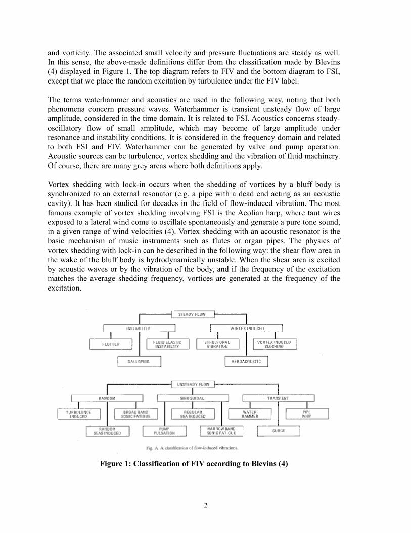
and vorticity. The associated small velocity and pressure fluctuations are steady as well. In this sense, the above-made definitions differ from the classification made by Blevins (4) displayed in Figure 1. The top diagram refers to FIV and the bottom diagram to FSI, except that we place the random excitation by turbulence under the FIV label. The terms waterhammer and acoustics are used in the following way, noting that both phenomena concern pressure waves. Waterhammer is transient unsteady flow of large amplitude, considered in the time domain. It is related to FSI. Acoustics concerns steady-oscillatory flow of small amplitude, which may become of large amplitude under resonance and instability conditions. It is considered in the frequency domain and related to both FSI and FIV. Waterhammer can be generated by valve and pump operation. Acoustic sources can be turbulence, vortex shedding and the vibration of fluid machinery. Of course, there are many grey areas where both definitions apply. Vortex shedding with lock-in occurs when the shedding of vortices by a bluff body is synchronized to an external resonator (e.g. a pipe with a dead end acting as an acoustic cavity). It has been studied for decades in the field of flow-induced vibration. The most famous example of vortex shedding involving FSI is the Aeolian harp, where taut wires exposed to a lateral wind come to oscillate spontaneously and generate a pure tone sound, in a given range of wind velocities (4). Vortex shedding with an acoustic resonator is the basic mechanism of music instruments such as flutes or organ pipes. The physics of vortex shedding with lock-in can be described in the following way: the shear flow area in the wake of the bluff body is hydrodynamically unstable. When the shear area is excited by acoustic waves or by the vibration of the body, and if the frequency of the excitation matches the average shedding frequency, vortices are generated at the frequency of the excitation.
Figure 1: Classification of FIV according to Blevins (4)
2
3. COUPLED VERSUS UNCOUPLED CALCULATIONS
Safety analysis sometimes requires the computer simulation of the behaviour of a piping system under severe excitation such as caused by a LOCA (Loss Of Coolant Accident). Conventional analyses are generally performed in an uncoupled way, i.e., first by calculating the fluid pressures as if the structure was fixed, and second by applying these pressures as external forces to the structure. Whether this approach is valid is the subject of the present section. The main effects of fluid-structure interaction are problem dependent. When compared to predictions of conventional waterhammer and uncoupled analyses, predictions including fluid-structure interaction may lead to: higher or lower extreme pressures and stresses, changes in the natural frequencies of the system, and more damping and dispersion in the pressure and stress histories. Fully fluid-structure coupled models are required to analyse flexible structures subjected to rapid excitation, in particular to assess accurately the anchor forces (5). FSI models give then a more accurate prediction of pressure, stress and displacement amplitudes, of natural and resonance frequencies, of damping, and of anchor and support forces. The classical theory of waterhammer predicts a square-wave pressure history (at the valve, friction neglected) in a reservoir-pipeline-valve system subjected to sudden valve closure (6, 7). It has been shown, amongst others, by Tijsseling and Heinsbroek (8) that this square wave is distorted in flexibly supported pipelines. Moving pipe (b)ends may (i) introduce higher-frequency pressure oscillations, (ii) make square waves "triangular" and consequently wavefronts less steep, (iii) change the system's main frequency and (iv) invalidate application of Joukowsky's formula. Many investigators have shown that the pressure amplitudes during a waterhammer event in a pipeline may exceed Joukowsky's value as a result of pipe flexibility. For example, figure 7c in (9) shows a Joukowsky overshoot of 100%. In general, the flexibility of pipe systems causes pressures higher than Joukowsky in the beginning of a transient event. Later on, in systems with movable bends, the pressures are lower than Joukowsky, because energy has been transferred from the fluid pulsation to the (mainly lateral) pipe vibration. The structural natural frequencies of a fluid-filled pipe system are usually obtained from an analysis in which the fluid is dead mass. The fluid natural frequencies, if required, are then obtained from an analysis in which the pipe system is rigid. This approach will fail in compliant systems with structural and fluid frequencies close to each other. Fluid-structure interaction by junction coupling - e.g. at movable (b)ends - will separate coinciding fluid and structural frequencies (as found without considering FSI). Moussou et al. (10) gave a most detailed study of a Z-shaped pipe system and they came to the conclusion that, due to FSI, fluid and structural frequencies cannot coincide. Thus, FSI prevents a certain type of resonance behaviour as seen in the uncoupled calculations for a single pipe with a vibrating closed end (11, 12) and for a pipeline with six movable bends (13). FSI prevents this type of resonance behaviour, because it prohibits coinciding fluid and structural frequencies. Uncoupled calculations predict a ‘super-resonance’, where
3
fully-coupled calculations do not. In this case the results of uncoupled calculations are much too conservative.
4. WATERHAMMER-INDUCED LOADS
One of the sources of severe transient loads on structures in nuclear power plants is waterhammer that can occur as a consequence of valve closing or opening during normal operation or in the accidental case of rupture in high-energy pipelines in single-phase or two-phase flows. Waterhammer may also appear in the case of cold-water injection into piping and other equipment filled with steam or steam-water mixtures, for instance if activating emergency core cooling systems or auxiliary feed water systems in nuclear power plants. Such transients are characterised by the formation and propagation of series of steep compression and rarefaction waves [Figure 2 (left) shows data obtained in the PPP test facility at Fraunhofer UMSICHT, Oberhausen, Germany, within the WAHALoads European project (14, 15)] and their complete or partial reflection at abrupt changes of pipe cross-section, in unrestrained bends and at flow connections to large reservoirs such as vessels or tanks. In all cases strong dynamic stresses are induced in the pipe walls, and high loads on the supports are generated. Although much progress has been achieved within the field of nuclear thermal hydraulics, the realistic prediction of fast transient two-phase flows remains a challenging task. This results mainly from the inhomogeneous nature of two-phase flow processes and the presence of strong mechanical non-equilibrium (different local velocities of the two phases) and thermal non-equilibrium (the temperatures of the two phases differ from the saturation temperature and from each other). Moreover, waterhammer caused by rapid condensation is controlled by the interfacial heat transfer between the steam and the sub-cooled water. Existing models for the condensation of steam in contact with sub-cooled water (contact condensation) do not describe the phenomenon with the required accuracy [see overview in (16)]. The models rely on coefficients for the inter-phase heat exchange, the values of which are subject to empirical adaptation. There is no unified theory to predict these coefficients on the basis of a physical understanding of the condensation process and the fluid mechanics of the two-phase flow. As a consequence, the determination of the expected dynamic pressures is not yet reliable. In nuclear industry, pressure waves propagate through complicated pipe systems interconnecting different components (e.g. pump, heat exchanger) and containing geometric and hydraulic peculiarities. Existing thermal-hydraulic codes, used currently in industry [for instance RELAP5 (17)], have significant deficiencies concerning the prediction of rapid and complicated characteristics of the waterhammer-type fast pressure transients. Although they provide numerically stable results for a number of flow conditions, numerical results of these codes suffer from the excessive numerical damping and dissipation which tends to smear discontinuities over several adjacent mesh elements. Only some specialised fast-dynamics codes based on the homogeneous equilibrium model for two-phase flow, using second-order accurate numerical methods and dedicated to the
4
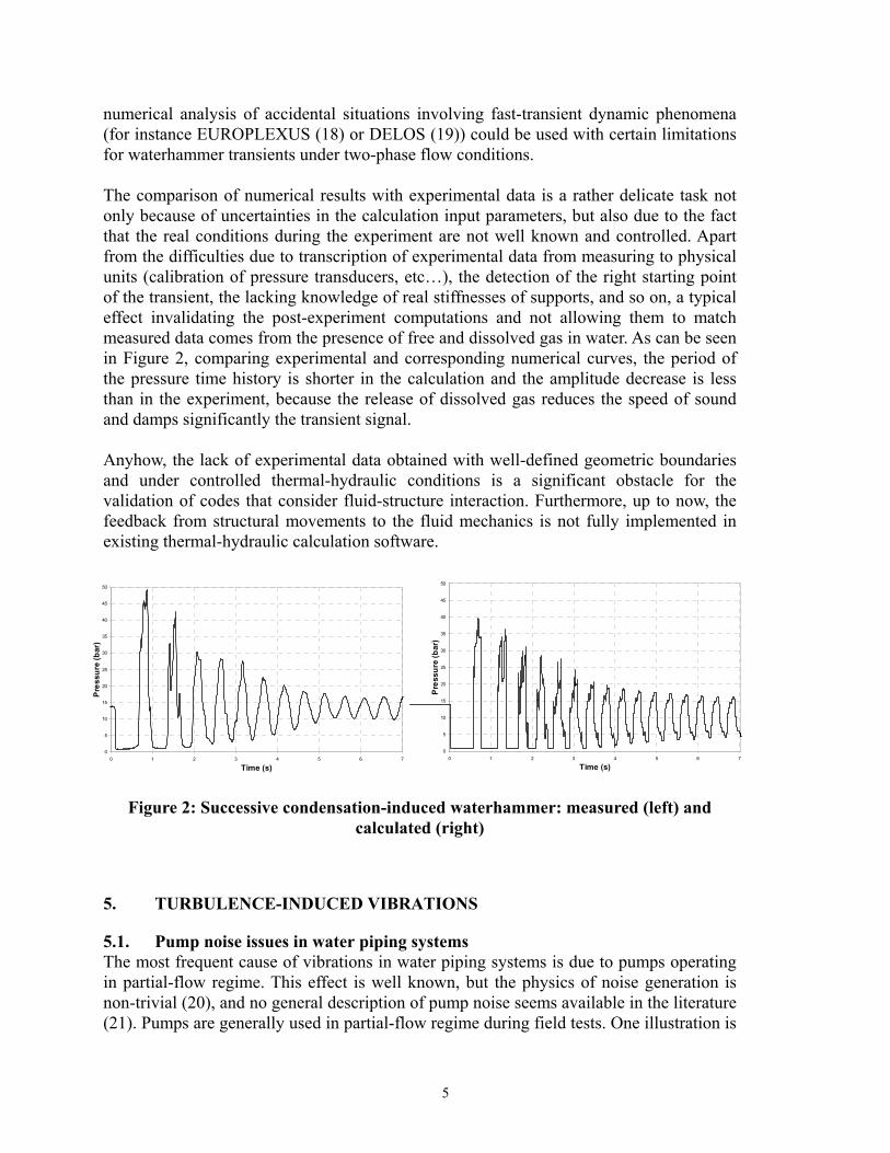
numerical analysis of accidental situations involving fast-transient dynamic phenomena (for instance EUROPLEXUS (18) or DELOS (19)) could be used with certain limitations for waterhammer transients under two-phase flow conditions. The comparison of numerical results with experimental data is a rather delicate task not only because of uncertainties in the calculation input parameters, but also due to the fact that the real conditions during the experiment are not well known and controlled. Apart from the difficulties due to transcription of experimental data from measuring to physical units (calibration of pressure transducers, etc…), the detection of the right starting point of the transient, the lacking knowledge of real stiffnesses of supports, and so on, a typical effect invalidating the post-experiment computations and not allowing them to match measured data comes from the presence of free and dissolved gas in water. As can be seen in Figure 2, comparing experimental and corresponding numerical curves, the period of the pressure time history is shorter in the calculation and the amplitude decrease is less than in the experiment, because the release of dissolved gas reduces the speed of sound and damps significantly the transient signal. Anyhow, the lack of experimental data obtained with well-defined geometric boundaries and under controlled thermal-hydraulic conditions is a significant obstacle for the validation of codes that consider fluid-structure interaction. Furthermore, up to now, the feedback from structural movements to the fluid mechanics is not fully implemented in existing thermal-hydraulic calculation software.
0
5
10
15
20
25
30
35
40
45
50
0 1 2 3 4 5 6 7
Time (s)
Pre
ssur
e (b
ar)
0
5
10
15
20
25
30
35
40
45
50
0 1 2 3 4 5 6 7
Time (s)
Pre
ssur
e (b
ar)
Figure 2: Successive condensation-induced waterhammer: measured (left) and
calculated (right)
5. TURBULENCE-INDUCED VIBRATIONS
5.1. Pump noise issues in water piping systems The most frequent cause of vibrations in water piping systems is due to pumps operating in partial-flow regime. This effect is well known, but the physics of noise generation is non-trivial (20), and no general description of pump noise seems available in the literature (21). Pumps are generally used in partial-flow regime during field tests. One illustration is
5

given in Figure 3, where lateral velocity spectra of a vibrating pipe are plotted at nominal-flow regime and at partial-flow regime. The pipe on which the measurements were made is a branch pipe 10” (273.1 mm) wide, and the flow throughout the pump varies from about 100 m³/h to about 500 m³/h. Figure 3 exhibits a typical pattern for the structural velocity spectrum in water piping systems. The lowest modes are dominated by structural mechanics and range from 10 to 30 Hz, whereas the higher modes involve FSI and are hard to distinguish from noise. Sharp peaks appear at the pump passing blade frequency, equal here to 150 Hz. In some frequency ranges, the difference of vibration level can reach one order of magnitude, which may be sufficient to expose small bore pipes to fatigue failure. The best defence against a high level of vibration in partial-flow regime would simply be to eliminate the partial-flow regime itself. If impossible, solutions can be found in structural modifications like mass or support additions (to change the natural frequencies of the pipes), or damper installations.
0.001
0.01
0.1
1
10
0 100 200 300 400 500Frequency (Hz)
Velocity spectrum
[mm/s/sqrt(Hz)]
Partial flow regime
Nominal flow regime
Figure 3: Structural velocity spectra of a piping system for different flow regimes
174261.5
87
0.01
0.1
1
10
100
0 50 100 150 200 250 300
Frequency (Hz)
Velocity spectrum
[mm/s/sqrt(Hz)]
Figure 4: Structural velocity spectra of a piping system excited by the pump blade
passing
6

Another kind of pump-induced vibrations occurs when one of the natural frequencies of a pipe coincides with the pump passing blade frequency, as shown in Figure 4. The pump operates at 5200 r.p.m., which generates a dominant peak at 87 Hz with higher harmonics at 174 Hz and at 261 Hz. As the vibration of the pipe is essentially due to the first peak, it can reasonably be assumed that the machinery-imposed 87 Hz peak coincides with a coupled frequency of the pipe.
5.2. Cavitation noise in butterfly valves Second to pumps in partial-flow regime, cavitating pressure-drop devices constitute a main source of vibrations in water piping systems. Basically, cavitation occurs in a valve or an orifice where the pressure falls below the vapour pressure. In highly turbulent flows such as those encountered in power plants, the lowest pressure appears in the heart of eddies as a result of centrifugal forces. Bubbles of vapour are then generated, which drift toward areas of higher pressure where they implode, generating acoustic pulses of short duration (22, 23). In the case of a high cavitation level, the bubble noise can be high enough to generate structural vibration and fatigue. The cavitation phenomenon is very sensitive to variations of the hydraulic regime. Figure 5 exhibits several velocity spectra, measured under different operating conditions, in a piping system where the main source of vibrations was a cavitating butterfly valve (24). The downstream pressure and the flow across the valve were changed, and so did the velocity spectra: a variation of 30 % of the flow can alter the structural velocity spectra by more than one order of magnitude. Hydraulic indicators are then required to describe the occurrence of cavitation and the noise it generates. The usual practical indicator of cavitation (22, 25) is the Thoma number which is defined as the ratio:
T = pdownstream / ∆p
Velocityspectrum
Differentflowsand
pressures
Figure 5: Structural velocity spectra of a cavitating piping system at different flow
regimes
7
0
2
4
6
8
10
12
14
0 50 100 150 200Hydraulic power in valve 13 VP (kW)
RM
S ve
rtic
al v
eloc
ity a
t ref
eren
ce p
oint
(mm
/sec
) Thoma < 0.50.5 < Thoma < 1.51.5 < Thoma < 4 Thoma > 4
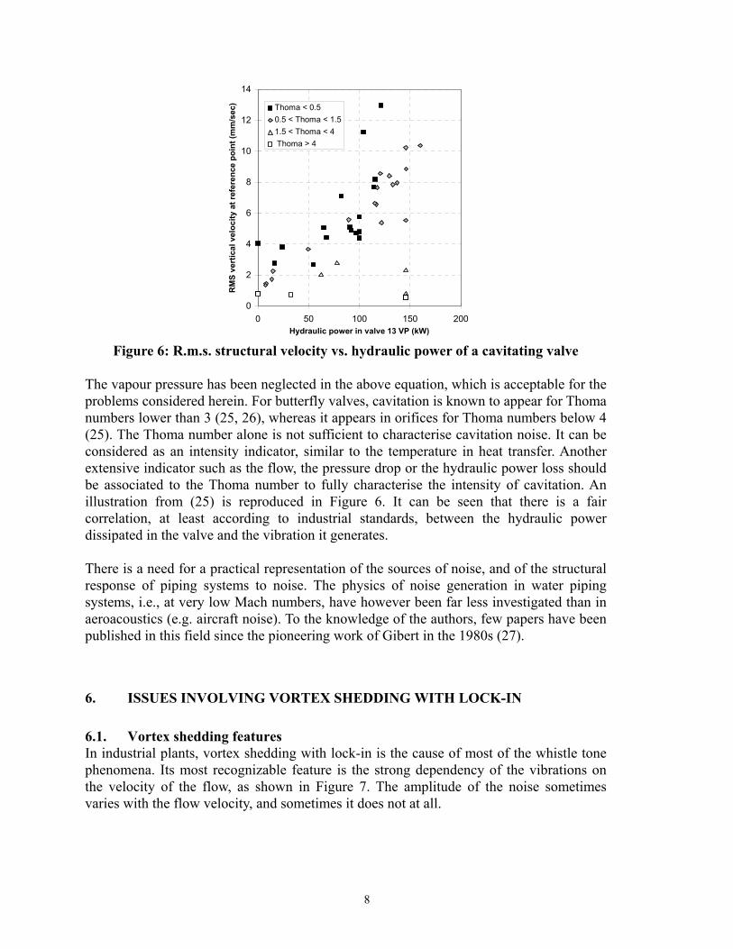
Figure 6: R.m.s. structural velocity vs. hydraulic power of a cavitating valve
The vapour pressure has been neglected in the above equation, which is acceptable for the problems considered herein. For butterfly valves, cavitation is known to appear for Thoma numbers lower than 3 (25, 26), whereas it appears in orifices for Thoma numbers below 4 (25). The Thoma number alone is not sufficient to characterise cavitation noise. It can be considered as an intensity indicator, similar to the temperature in heat transfer. Another extensive indicator such as the flow, the pressure drop or the hydraulic power loss should be associated to the Thoma number to fully characterise the intensity of cavitation. An illustration from (25) is reproduced in Figure 6. It can be seen that there is a fair correlation, at least according to industrial standards, between the hydraulic power dissipated in the valve and the vibration it generates. There is a need for a practical representation of the sources of noise, and of the structural response of piping systems to noise. The physics of noise generation in water piping systems, i.e., at very low Mach numbers, have however been far less investigated than in aeroacoustics (e.g. aircraft noise). To the knowledge of the authors, few papers have been published in this field since the pioneering work of Gibert in the 1980s (27).
6. ISSUES INVOLVING VORTEX SHEDDING WITH LOCK-IN
6.1. Vortex shedding features In industrial plants, vortex shedding with lock-in is the cause of most of the whistle tone phenomena. Its most recognizable feature is the strong dependency of the vibrations on the velocity of the flow, as shown in Figure 7. The amplitude of the noise sometimes varies with the flow velocity, and sometimes it does not at all.
8

Vortex shedding is commonly characterised by the so-called Strouhal number, which is the product of the frequency at which the oscillation can appear and of a characteristic distance, divided by the flow velocity. In the frame of internal flows, vortex shedding occurs in valves, tee-junctions, single and multihole orifices (see Figure 8), shallow cavities, and almost every possible kind of pressure-drop device, as a recent publication has shown (28). Each pressure drop device is characterised by a certain value of the Strouhal number, ranging from 0.2 to 2, which predicts the frequency of the whistle tone. The identification of the resonator involved in a vortex shedding case may be the difficult part of an investigation. Acoustics of the fluid, mechanics of the structure, as well as FSI, can generate resonators in a vessel or in a pipe, and modal analysis is likely to provide many candidates. There is a need for a rule which would help to select the proper mode among many others. Another research issue would be to determine an amplitude condition for the lock-in to occur. This issue can be explained using the language of electronics, where self-oscillating devices are described as the combination of an amplifier and a feed-back loop. The condition of self-oscillation is that the global gain of the amplifier and the feed-back loop must be higher than unity for the frequency of oscillation. In physical words, one would expect the resonator to give back enough energy to the vortex shedding area for the self-oscillation to occur. To the authors’ knowledge, no general rule exists today which would express this amplitude condition, and it is suggested that some further research should be undertaken in this direction. Finally, it is still an open question whether vortex-shedding issues occur less often in low Mach-number regimes because the resonators are less efficient, or because the noise amplitude is lower.
0
2
4
6
8
10
12
520 525 530 535 540Frequency (Hz)
Vel
ocity
spec
trum
(mm
/s/sq
rt(H
z))
Flow = 350 m³/hFlow = 346 m³/hFlow = 332 m³/hFlow = 318 m³/h
Figure 7 : Vibration peak vs. flow velocity in a vortex shedding case (29)
9
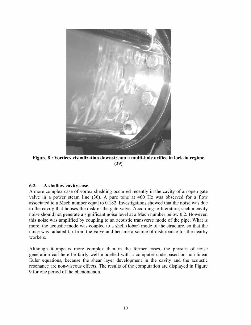
Figure 8 : Vortices visualization downstream a multi-hole orifice in lock-in regime
(29)
6.2. A shallow cavity case A more complex case of vortex shedding occurred recently in the cavity of an open gate valve in a power steam line (30). A pure tone at 460 Hz was observed for a flow associated to a Mach number equal to 0.182. Investigations showed that the noise was due to the cavity that houses the disk of the gate valve. According to literature, such a cavity noise should not generate a significant noise level at a Mach number below 0.2. However, this noise was amplified by coupling to an acoustic transverse mode of the pipe. What is more, the acoustic mode was coupled to a shell (lobar) mode of the structure, so that the noise was radiated far from the valve and became a source of disturbance for the nearby workers. Although it appears more complex than in the former cases, the physics of noise generation can here be fairly well modelled with a computer code based on non-linear Euler equations, because the shear layer development in the cavity and the acoustic resonance are non-viscous effects. The results of the computation are displayed in Figure 9 for one period of the phenomenon.
10

Figure 9: Computer simulation of the vortex generation in a shallow cavity case (30);
left: dark zone = high pressure; right: dark zone = high vorticity On the right side of the figure, snapshots of the vorticity field in the cavity are shown: they highlight the vortex shedding mechanism in the cavity and the vortex interaction with the downstream corner. On the left side, snapshots of the pressure field in the duct are shown: the first transverse mode is excited and coupled with the cavity source radiation.
7. SPECIAL FEATURES OF INDUSTRIAL FSI ISSUES
Industrial investigations generally concern troubleshooting or they aim at the definition of rules and guidelines. In contrast to most academic research, many unchecked assumptions are often necessary during the investigation. Whether these assumptions are valid or not is a ‘non-scientific’ issue, which has nevertheless a strong influence on the quality of the results. As the two cases developed hereafter will illustrate, there is a need for simple and robust methods suited to industrial practice.
7.1. Troubleshooting investigation A troubleshooting investigation can seldom be achieved according to the academic research standards of completeness and validation. When an expert engineer is summoned to solve a FSI case in an industrial plant, he/she is generally asked to fix it in a very short time, e.g., a few days for performing field tests and one more week for the final report
11

including a proposed solution of the problem. Depending on the case study, the expertise can be successful or not, because FSI in practical situations is not fully understood today.
Figure 10: Schematic drawing of the pipe generating a 12 Hz tone As an illustration, one of the authors investigated recently a pure tone phenomenon at 12 Hz, which occurred in the water piping system sketched in Figure 10. The fluid is at rest except in the lower branch where the fluid flow varies from 1050 to 1200 m³/h. A pure tone at 12 Hz appears at the end of the closed branch, and at the end of the upper line when the left valve is open. Vortex shedding from the first T-junction is probable because its Strouhal number (based on the T-diameter and the flow velocity) would be close to 1 at the 12 Hz frequency, and one would expect an acoustic resonator to be involved in the assumed self-oscillation. However, the vibration still happens when the left valve is closed, which is in contradiction with the idea of an acoustic resonator, because the opening of the valve would change its natural frequency. The authors suspected after the tests a mechanical feedback, i.e. a vertical vibration of the T-piece due to a structural mode. The displacement of the T-piece could be enough to trigger the oscillation of the shear layer. However, as a modal analysis of the structure has not been performed, this explanation is only a wild guess. Due to plant constraints, no other tests could be performed, and the case is still unsolved. This is a typical case of an unexpected FSI effect, which requires time and academic research to be fully understood.
7.2. From design to reality Another industrial issue deals with the gap between design and reality. Most of the time, engineers expect a specification of a piping system based on design data to be accurate. As regards vibrations, this assumption is often incorrect: fixed points have finite stiffnesses, many supports do not block pipes due to their clearance, and the acoustic boundary conditions are everything but well-defined.
From the experience of the authors, to accurately describe and model the low-frequency dynamic behaviour of industrial piping systems beyond the first natural modes appears hopeless. This conclusion is derived from significant efforts made in the past years. An
12

illustration can be given by considering the piping system shown in Figure 11. It is a pump-to-pump water piping system made of stainless steel, with an outer diameter of 0.219 m, a thickness of 3.76 mm and a radius of curvature equal to 0.305 m. This piping system has the same design on several French nuclear plants. Vibration commissioning was required, so that data became available on five identical piping systems operating at the same hydraulic regime. The structural velocity spectra of the third elbow in the vertical direction are plotted in Figure 12. As can be seen, the similarity is poor, and only the range of the first natural frequencies and the average level can be held as meaningful. From a scientific point of view, the measurements are bad. Considered from an industrial point of view, these measurements are the best that can be made without expert analysis, including modal analysis and accurate control of the hydraulics of every individual piping system. Computer simulation can shed some light on this disagreement in results. In most piping systems, the vibrations from 2 Hz to some 500 Hz can be described using beam theory for the structure and plane wave acoustics for the fluid. The first modes of the pipe are generally mechanical, whereas the modes of higher order involve acoustics and FSI. As many academic papers proved it, beam theory is well suited to describe the behaviour of simple systems, provided that the boundary conditions are well defined. The difference of the frequency peaks in Figure 12 can be partly explained assuming that the stiffnesses of the supports of the pipes were different from one plant to the other. The differences can be reproduced by calculations, as shown in Figure 13, where the response of the pipe to a white noise pressure source is plotted for different elbow flexibilities and for different conditions of support flexibility.
Figure 11: Layout of piping system
13

0.01
0.1
1
10
0 50 100 150 200Frequency (Hz)
Vel
ocitr
y sp
ectr
um(m
m/s
/sqr
t(H
z))
Figure 12: Poor similarity of measured structural velocity spectra in five nominally
identical piping systems
0.01
0.1
1
10
0 50 100 150 200Frequency (Hz)
Vel
ocity
spe
ctru
m
(mm
/s/s
qrt(
Hz)
)
0.01
0.1
1
10
0 50 100 150 200Frequency (Hz)
Vel
ocity
spe
ctru
m
(mm
/s/s
qrt(
Hz)
)
Figure 13: Computed influence of the flexibility of the elbows (left) and of the pump
anchors (right) on the response of the pipe In practice, computer simulation can be used for control purposes, to obtain values of velocities and accelerations below which the structure is not exposed to fatigue failure. Defining the supports according to their function would in most cases lead to screening values of the maximum velocities or accelerations: the supports are usually designed as blocking the rotations, but the actual supports have finite stiffnesses which enhances the rotations. As a consequence, for a given stress in the pipe, the deflection with the actual support would be higher than the deflection with an ideal support. One issue would be to determine whether a structural dynamics code can be used for determining the fatigue criteria, or whether FSI effects necessitate fully-coupled calculations. It is yet the belief of two authors of the present paper that the deviation in the pipe parameters would generate more deviation in the dynamics of the pipes than FSI would ever do, whereas one of the authors strongly supports the opposite view.
14

8. CONCLUSION
This paper presents FSI and FIV in liquid-conveying piping systems from an industrial point of view. It describes seven typical problems (in power plants) featuring excessive pipe vibration and/or fluid pulsation (including waterhammer). The underlying FSI mechanisms are explained and measured evidence is given. One mysterious problem shows the dilemma of the engineer: with a limited amount of data, he/she has to come to the right conclusion. Experience is what counts here, and it is of utmost importance that existing experience is being written down in textbooks like Refs (1, 2, 3, 4). Academia can help in the further development of knowledge and simulation tools, but it cannot take away the practical problem of lack of reliable (and accurate) data and information. Often the problem is simply too complex to handle, and one has to fall back on basic principles and simplified models. In this respect, there is a special need for guidelines and rules, preferably incorporated in international Codes and Standards.
9. ACKNOWLEDGEMENTS
Financial support for part of this work was provided by the project WAHALoads (FIKS-CT-2000-00106) included in the 5th Framework Programme and supported by the European Commission.
The Surge-Net project is supported by funding under the European Commission’s Fifth Framework ‘Growth’ Programme via Thematic Network “Surge-Net” contract reference: G1RT-CT-2002-05069. The authors of this paper are solely responsible for the content and it does not represent the opinion of the Commission. The Commission is not responsible for any use that might be made of data therein.
10. REFERENCES
(1) Au-Yang, M. K. (2001), Flow-Induced Vibration of Power and Process Plant Components: A Practical Workbook, ASME Press
(2) Weaver, D.S., Ziada, S., Au-Yang, M.K., Chen, S.S., Païdoussis, M.P., and Pettigrew, M.J. (2000), Flow-induced vibrations in power and process plant components - Progress and prospects, ASME Journal of Pressure Vessel Technology 122 339-348
(3) Naudascher, E. and Rockwell D. (1994), Flow-Induced Vibrations: An Engineering Guide, IAHR Hydraulic Structures Design Manual 7, AA Balkema
(4) Blevins, R. D. (1990), Flow-Induced Vibration (2nd edition), Van Nostrand Reinhold
(5) S.Potapov, F.Bliard, F.Tephany, Simulation de la décompression du réacteur HDR avec le code de dynamique rapide EUROPLEXUS, Revue Européenne des éléments finis, 2002, Vol 11, n°5, p.667-694
(6) Chaudhry MH (1987), Applied Hydraulic Transients (2nd edition), Van Nostrand Reinhold
(7) Wylie, E.B. and Streeter, V.L. (1993), Fluid Transients in Systems. Englewood Cliffs, New Jersey, USA: Prentice Hall
15

(8) Tijsseling, A.S. and Heinsbroek, A.G.T.J. (1999) The influence of bend motion on waterhammer pressures and pipe stresses Proceedings of the 3rd ASME & JSME Joint Fluids Engineering Conference, Symposium S-290 Water Hammer (Editor JCP Liou), San Francisco, USA, July 99, ASME-FED 248 Paper FEDSM99-6907, 1-7, ISBN 0-7918-1961-2 (CD-ROM) or ISBN 0-7918-1978-7
(9) Tijsseling, A.S. (1996), Fluid-structure interaction in liquid-filled pipe systems: a review, Journal of Fluids and Structures 10 109-146
(10) Moussou, P., Vaugrante, P., Guivarch, M., and Seligmann, D. (2000), Coupling effects in a two elbows piping system, Proceedings of the 7th International Conference on Flow Induced Vibrations, Luzern, Switzerland, 579-586
(11) Müller, W.Ch. (1989), DAPS, a code for coupled analysis of pressure transients in pipes, Kerntechnik 54(3) 149-152
(12) Wiggert, D.C. and Tijsseling, A.S. (2001), Fluid transients and fluid-structure interaction in flexible liquid-filled piping, ASME Applied Mechanics Reviews 54 455-481
(13) Kellner, A. and Schönfelder, C. (1982), Die Bedeutung der Fluid/Struktur-Wechselwirkung für die Druckstoßbelastung von Rohrleitungen. (The effect of fluid/structure-interaction on pressure pulse loads on pipes.), 3R international 21 443-449 (in German)
(14) WAHALoads contract FIKS-CT-2000-0016, Annex I, Description of work: Two-phase flow water hammer transients and induced loads on materials and structures of nuclear power plants, September 2000.
(15) Data Evaluation Report on PPP water hammer tests, cavitation caused by rapid valve closing, WAHALoads Project, Deliverable D35 by Fraunhofer Institut für Umwelt Sicherheits und Energietechnik UMSICHT, June 2003.
(16) I.Tiselj, A.Horvat, Accuracy of the operator splitting technique for two-phase flow with stiff source terms, Proc. of ASME Fluids Engineering Division Summer Meeting, Montreal, Quebec, Canada, July 14-18, 2002.
(17) RELAP5/MOD3 code manual, NUREG/CR-5535, 1995.
(18) EUROPLEXUS code User’s Manual, (available on http://europlexus.jrc.it)
(19) DELOS : fast dynamic software of TERM-UCL division of the Applied Science Faculty,1995.
(20) Szenasy, F.R. (1992), Vibration and noise in pumps, in Centrifugal Pumps - Design and Applications, Lobanoff & Ross ed., Gulf Publishing Company, Houston
(21) 1st int. symp. on Pump noise & vibrations, (1993), Clamart, ISBN 2-85400-274-1, CETIM, Senlis
(22) Lecoffre, Y. (1994) La cavitation - traqueurs de bulles , Hermès, Paris (in French)
(23) Axisa, F. (2001), Modélisation des systèmes mécaniques – Vibrations sous écoulement, Hermès, Paris (in French)
(24) Moussou, P., Cambier, C., Lachene, D. Longarini, S., Paulhiac L. and Villouvier V. (2001), Vibration investigation of a French PWR power plant piping system caused by cavitating butterfly valves, in PVP-Vol. 420-2, Flow-induced Vibration Volume2: Axial Flow, Piping Systems, Other Topics, 99-106, ASME
(25) Tullis, J.P. (1989), Hydraulics of Pipelines: Pumps, Valves, Cavitation, Transients, John Wiley & Sons
(26) Blake, W.K. (1986), Mechanics of Flow-Induced Sound and Vibration, Volume I, General Concepts and Elementary Sources, Academic Press
(27) Gibert R-J (1988), Vibrations des Structures - Interactions avec les Fluides - Sources d'Excitation Aléatoires, Collection de la Direction des Etudes et Recherches d'Electricité de France 69, ISSN 0399-4198 (in French)
16

17
(28) Motriuk, R. (2003), A perforated conical strainer as an example of an acoustic noise generator in PVP-Vol. 465, Flow-induced Vibration PVP2003-2089, 185-191, ASME
(29) Moussou, P., Caillaud, S., Villouvier, V., Archer, A., Boyer, A., Rechu, B. Benazet, S. (2003) Vortex-shedding of a multi-hole orifice synchronized to an acoustic cavity in a PWR piping system, in PVP-Vol. 465, Flow-induced Vibration PVP2003-2086, 161-168, ASME
(30) Lafon, Ph., Lambert, Ch., Devos, J.P. and Caillaud, S. (2002) , Aeroacoustical coupling and its structural effects on a PWR steam line – Numerical investigations of flow acoustic coupling in a subsonic flow past a shallow cavity, IMECE2002-3361, in Proc. of IMECE 2002, November 17-22, New Orleans