Industrial & Commercial Workstream: Summary Report
37
Industrial & Commercial Workstream: Summary Report Author Organisation Revision Description Date David Parish Centrica - 1 st draft 31/09/20 David Parish Centrica - Release 31/10/20
Transcript of Industrial & Commercial Workstream: Summary Report
Industrial & Commercial Workstream:
Summary Report
Author Organisation Revision Description Date
David Parish Centrica - 1st draft 31/09/20
David Parish Centrica - Release 31/10/20
1
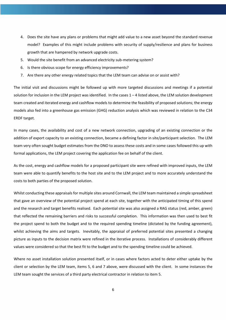
Contents
1. Introduction ................................................................................................................................................................. 3
2. Scope ............................................................................................................................................................................ 3
2.1 Drivers .................................................................................................................................................................... 3
2.2 Organisations Eligible for Inclusion ........................................................................................................................ 4
2.3 Qualifying Actions, Technologies and Equipment .................................................................................................. 4
3. Methodology ................................................................................................................................................................ 5
3.1 Engagement ........................................................................................................................................................... 5
3.2 Appraisal Process and Site Selection ...................................................................................................................... 5
3.3 Procurement of SGEI Assets and Professional Services ......................................................................................... 7
4. Outcomes ..................................................................................................................................................................... 7
4.1 Summary of Appraisals and SGEI Site Selection ..................................................................................................... 7
4.2 Summary of Non-SGEI Outcomes .......................................................................................................................... 8
4.3 SGEI Site Descriptions, Process, Installation details and Outcomes ...................................................................... 8
4.3.1 The Olde House Farm Cottages – 90 kW Flow Battery ................................................................................... 9
4.3.2 The Carbis Bay Hotel & Estate – 70 kW CHP ................................................................................................. 10
4.3.3 Lower Ninestones – 2.5 MW Solar Farm ....................................................................................................... 12
4.3.4 Wave Hub – 1.5 MW Battery ........................................................................................................................ 13
4.3.5 Cornwall Council, Ventonteague – 2.3 MW Wind Turbine ........................................................................... 17
4.3.6 SPR Carland Cross Windfarm – 1 MW Battery .............................................................................................. 21
4.4 Advanced Electricity Sub Metering Systems ........................................................................................................ 24
4.5 Non Financial Support .......................................................................................................................................... 25
5. Summary of Spending ................................................................................................................................................ 26
6. Discussion ................................................................................................................................................................... 27

2
6.1 Safeguarding the Distribution Network ............................................................................................................... 28
6.2 Connections for the Provision of Flexibility ......................................................................................................... 30
7. Conclusion .................................................................................................................................................................. 33
Appendix A – Wave Hub 3 MW MIC Budget Estimate .................................................................................................... 34

3
1. Introduction
Centrica’s Cornwall Local Energy Market (LEM) is a pioneering project that demonstrates a coordinated approach to
procuring distributed demand and generation flexibility on the electricity networks. This approach has the potential
to unlock capacity on the networks and to provide much needed balancing control, as the conventional thermal
generation assets are taken offline. Such capacity and control are important in facilitating a far deeper penetration of
renewable energy on the UK electricity networks in order that the UK can meet its decarbonisation targets. Invoking
a flexible control methodology for the networks will be an important part of the energy transition towards net zero
carbon.
The Cornwall Local Energy Market project comprised of five key workstreams:
• LEM flexibility trading platform, development and trials.
• Residential battery storage installation and trials.
• Industrial & Commercial engagement, installations and support.
• Project management, communications and compliance.
• Research and reporting.
This report summarises the activities and outcomes associated with the Industrial & Commercial (I&C) workstream.
The I&C workstream was tasked with satisfying several important targets placed upon the project by the European
Regional Development Fund (ERDF). These targets, together with the core aims of the project, shaped the scope and
methods employed within this work.
2. Scope
2.1 Drivers
The purpose of the I&C workstream has been to engage with enterprises in Cornwall, make them aware of the
burgeoning flexibility markets, assist with energy related matters, enrol suitable participants to the LEM platform trials
and to promote a response to the new market opportunities. A significant proportion of the LEM project budget has
been made available to achieve these aims; this has included the installation of energy storage and generation assets
at I&C sites.
The ERDF targets that further influenced the I&C workstream are as follows:
a) C1 – Number of enterprises receiving support

4
b) C2 – Number of Enterprises receiving grants (this is a subset of C1)
c) C4 – Number of enterprises receiving non-financial support (this is a subset of C1)
d) C26 – Number of enterprises cooperating with research entities
e) C28 – Number of enterprises supported to introduce new to the market products
f) C29 - Number of enterprises supported to introduce new to the firm products
g) C30 – Additional capacity for renewable energy production
h) C34 – Estimated GHG reductions
Note: Targets within categories C28 and C29 were removed from the scope midway through the project.
2.2 Organisations Eligible for Inclusion
Enterprises qualified for inclusion within the Cornwall LEM project from the following groups providing that they are
based or have a registered office in Cornwall:
• Industrial (e.g. manufacturing, mining)
• Commerce and business (e.g. retail, warehouse, hospitality, professional services)
• Community organisations (e.g. Community energy groups, sports clubs, cooperatives)
• Local authorities (e.g. county council, parish council)
• Utility companies (e.g. water company)
• Education (i.e. schools, colleges and universities)
• Renewable energy research, development and operations
• Agriculture
• Sports and leisure
2.3 Qualifying Actions, Technologies and Equipment
The actions and installations eligible for funding via the LEM project align to the aims of the project and the conditions
of the ERDF funding, including the targets described above. These actions and installations fall into the following
categories:
1) Installation of significant capital equipment at participating client sites. Such assets are described as Smart
Grid Energy Infrastructure (SGEI) and as such have the capability to provide or facilitate, flexibility services to
the electricity networks. Assets in this category are procured by the LEM project and must be owned by
Centrica PLC for five years after project completion, under the ERDF rules. The participating client might or
might not contribute to the scheme by funding, for instance; civils works, ancillary or related equipment.

5
2) Grant award of £1000 or more towards the cost of an advanced electricity sub metering system. Centrica’s
own wireless solution is made available under this offer (https://www.centricabusinesssolutions.com/energy-
solutions/products/energy-insight) but alternative systems also qualify.
3) Non-financial assistance in the form of energy related expertise, a minimum of 12 hours applies.
3. Methodology
The overarching ambition which underpins this methodology is to maximise the research value achieved with funds
that include public money, whilst delivering benefit to host sites and simultaneously satisfying the ERDF targets. To
this end, it was necessary to appraise a large number of potential opportunities and to select those that collectively,
best achieved this ambition within the project’s budget and time constraints.
3.1 Engagement
Potential host and participant organisations were sought out by the LEM team using the following techniques:
• Messaging via the local chamber of commerce
• Local newspaper advertising
• Using existing professional and personal contacts
• Cold calling organisations
3.2 Appraisal Process and Site Selection
Once contact was established with an organisation, typically an arrangement was made to visit the site, conduct an
initial walk-through survey and to discuss the site’s energy situation and forward strategy. This visit would normally
be made by one of the project’s energy engineers although some survey work was subcontracted to a third party.
Surveys would be seeking to identify opportunities with a general hierarchy as follows:
1. Does the site have existing assets that could provide flexibility responses, with or without some modification
or additional control system? Examples of this might be standby generator(s), combined heat & power plant
(CHP), batteries, large loads that can be cycled according to network needs, etc.
2. Does the site have existing connections to the distribution network that can accommodate flexibility
responses, i.e. does the site have an export connection and import connection of sufficient capacity or an
indication from the distribution network operator (DNO) that this is feasible?
3. Does the site have the potential to install renewable energy generation and might such generation be used to
provide flexibility services?
Applying local knowledge
6
4. Does the site have any plans or problems that might add value to a new asset beyond the standard revenue
model? Examples of this might include problems with security of supply/resilience and plans for business
growth that are hampered by network upgrade costs.
5. Would the site benefit from an advanced electricity sub-metering system?
6. Is there obvious scope for energy efficiency improvements?
7. Are there any other energy related topics that the LEM team can advise on or assist with?
The initial visit and discussions might be followed up with more targeted discussions and meetings if a potential
solution for inclusion in the LEM project was identified. In the cases 1 – 4 listed above, the LEM solution development
team created and iterated energy and cashflow models to determine the feasibility of proposed solutions; the energy
models also fed into a greenhouse gas emission (GHG) reduction analysis which was reviewed in relation to the C34
ERDF target.
In many cases, the availability and cost of a new network connection, upgrading of an existing connection or the
addition of export capacity to an existing connection, became a defining factor in site/participant selection. The LEM
team very often sought budget estimates from the DNO to assess these costs and in some cases followed this up with
formal applications, the LEM project covering the application fee on behalf of the client.
As the cost, energy and cashflow models for a proposed participant site were refined with improved inputs, the LEM
team were able to quantify benefits to the host site and to the LEM project and to more accurately understand the
costs to both parties of the proposed solution.
Whilst conducting these appraisals for multiple sites around Cornwall, the LEM team maintained a simple spreadsheet
that gave an overview of the potential project spend at each site, together with the anticipated timing of this spend
and the research and target benefits realised. Each potential site was also assigned a RAG status (red, amber, green)
that reflected the remaining barriers and risks to successful completion. This information was then used to best fit
the project spend to both the budget and to the required spending timeline (dictated by the funding agreement),
whilst achieving the aims and targets. Inevitably, the appraisal of preferred potential sites presented a changing
picture as inputs to the decision matrix were refined in the iterative process. Installations of considerably different
values were considered so that the best fit to the budget and to the spending timeline could be achieved.
Where no asset installation solution presented itself, or in cases where factors acted to deter either uptake by the
client or selection by the LEM team, items 5, 6 and 7 above, were discussed with the client. In some instances the
LEM team sought the services of a third party electrical contractor in relation to item 5.

7
3.3 Procurement of SGEI Assets and Professional Services
All contracts with a value above £25,000 were procured following National Rules in line with European Social
Investment Fund (ESIF) Programme procurement guidance. These require the opportunity to advertised, a clear
specification to be issued to interested bidders, fair and up-front scoring criteria to be published and used in scoring
and selection of the winning bidder based on the ‘most economically advantageous tender’.
Equality and diversity and environmental sustainability measures and checks were included in Invitations to tender,
usually in the form of the Contractor Competency Questionnaire which was issued for procurement of large-scale
supply and install of works or equipment. Tenders were scored against this questionnaire which includes HSE criteria
and policies, sustainability, corporate and social responsibility and equality and diversity requirements of the
company. These are over and above the requirements of the funder.
Note 1: Centrica is not a Contracting Authority or Utility; this means that it is not subject to the Public Contracts
Regulations 2015 or the Utilities Contracts Regulations 2016. Paragraph 22 of Chapter 6 of the Procurement Guidance
sets out that Centrica must therefore apply National Rules to the awarding of contracts.
Note 2: A notable exception to the above procurement process is the procurement of connections from the DNO. In
this case the rules allow for such instances that result from monopoly service providers.
4. Outcomes
4.1 Summary of Appraisals and SGEI Site Selection
Contact was made with 252 eligible businesses and organisations between March 2017 and May 2020. Of these, 32
sites were assessed for the installation of smart grid energy infrastructure such as a battery, CHP unit or renewable
energy generation equipment. In these cases, the energy flows of the existing site and the solutions being considered,
were numerically modelled and the associated costs and revenues were built into cashflow forecasts. On the basis of
the numerical modelling, 14 potential client sites were provided with a formal written proposal for the installation of
SGEI. Six of these proposals resulted in the provision of SGEI by the LEM project, as follows:
1. Connection equipment relating to a 90 kW x 1.08 MWh vanadium redox flow battery at The Olde House Farm
Cottages, Wadebridge.
2. Procurement and supply of two 35 kWe CHP units at the Carbis Bay Hotel & Estate, St Ives.
3. Connection works and equipment relating to a 2.47 MW PV array at Lower Ninestones Solar Farm.
4. Procurement, supply and installation of a 1.5 MW x 1.5 MWh lithium ion battery at Wave Hub, Hayle.

8
5. Connection works, equipment and civil engineering works relating to a 2.3 MW wind turbine at Cornwall
Council’s Ventonteague site.
6. Procurement, supply and installation of a 1.08 MW x 1.08 MWh lithium ion battery at Scottish Power
Renewables’ Carland Cross Windfarm.
4.2 Summary of Non-SGEI Outcomes
Of the 252 businesses and organisations contacted, 108 were offered a grant towards the cost of installing an advanced
electricity sub-metering system (ERDF C2 target); 80 of these offers were accepted, the vast majority opting for
Centrica’s wireless sensors, hub and cloud based data portal known as Power Radar.
Additionally, 32 businesses and organisations received non-financial support according to the ERDF C4 target. The full
set of targets and outcomes are provided in Table 1.
Table 1: ERDF project targets and outcomes.
Identifier Target Outcome Comments
C1 125 organisations 112 Received combinations of the following business support to improve resource efficiency: Surveys, energy monitoring and support, training, grants.
C2 58 organisations 80 Received grants for energy monitoring equipment.
C4 60 organisations 111 Received extended business support to improve resource efficiency.
C26 20 organisations 20 Businesses engaging in the LEM programme Knowledge Exchange Partnership
C30 2 MW installed renewable energy capacity
4.951 MW
C34 5,600 tonnes CO2e/yr GHG saving
9,656 tonnes
4.3 SGEI Site Descriptions, Process, Installation details and Outcomes
The following sub-sections describe the sites that were progressed with SGEI equipment. Care is taken that this
reporting properly describes the use of the project funds but observes the commercial sensitivity of the recipient sites.

9
4.3.1 The Olde House Farm Cottages – 90 kW Flow Battery
The Olde House is a 550 acre working farm at Chapel Amble, near Wadebridge. The site includes 27 holiday cottages
and five further buildings that offer larger group accommodation. The site also includes an indoor heated swimming
pool and a small multi-use venue suitable for conferences etc.
There are two network electricity supplies to the farm, one of these being dedicated to the working farm and the other
to the holiday centre; the latter being the subject of the LEM project and this report. The holiday site has a 245 kW
ground mounted PV array which is connected behind the meter (BTM) to feed directly to the onsite loads. However,
the onsite loads are dominated by late afternoon and evening use of electric water heaters, cookers and other
equipment. This creates a timing mismatch between the PV generation and the load, resulting in poor onsite
utilisation of the renewable energy and low value spill onto the distribution network. This condition was recognised
by the team at The Olde House and they made contact with RedT Energy, a company developing a vanadium redox
flow battery. It was recognised that the longer duration energy storage capability of a flow battery would allow the
solar PV energy to be stored for use in the evenings or nighttime, an action sometimes termed as ‘renewables firming’.
The LEM project team contacted The Olde house and RedT Energy and an agreement was reached whereby the LEM
project would contribute to a flow battery solution at the site and utilise the unit as a flex asset in the LEM platform
trials.
The technical details of the RedT Energy installation are as follows:
• Generation 1, vanadium redox flow battery.
• 90 kW power rating.
• 1.08 MWh energy storage comprising 6 x 180 kWh containerised modules.
• DNO connection - G59 connection code (parallel generation equipment).
o G100 export limitation applied.
Modelling of the energy flows by the LEM team predicted that although a large proportion of the PV generation would
be captured by the flow battery, the losses attributable to the flow battery are of a scale that would negate the
financial advantage gained by the improved onsite utilisation. The generation 1 vanadium redox flow battery and
ancillary equipment would achieve a full turnaround efficiency of approximately 65%, a value that improves somewhat
with generation 2 and generation 3 technology.
Whilst the client was pleased to be utilising their own solar PV energy there was still a desire to see some financial
advantage from the flow battery. Therefore, the LEM team arranged for a prototype ‘pass through’ supply tariff to be

10
offered to The Olde House from British Gas, a Centrica company. The pass-through tariff allows the site to experience
the price volatility of the electricity market and to act accordingly. When this supply contract was activated, RedT
Energy were able to adopt an alternative run regime whereby the flow battery charged from the grid at low cost during
the early hours of the morning (around 01.00 – 05.00), topped up with solar PV during the day and then supplied
energy to the site during the peak demand of the evening. With this run regime in place, the flow battery provided a
meaningful saving to the client.
Unfortunately, after some months of operation, the generation 1 vanadium redox flow battery failed and RedT Energy
committed to replacing it with a generation 2 unit; it is understood that this work is in progress at the time of issuing
this report.
Figure 1: LH - LEM Project Manager, Sophie Orme and RedT Energy CEO, Scott McGregor beside one of the flow battery modules.
RH – One of the six modules being positioned during the construction phase.
4.3.2 The Carbis Bay Hotel & Estate – 70 kW CHP
The Carbis Bay Hotel & Estate is located in Carbis Bay, less than one mile from St Ives. The Estate encompasses the 25
acre beach and in 2017 it included the main 47 room hotel, 14 guest apartments, two houses, a beach shop/cafe, the
surf lifesaving club and the boat hut used by St Ives Pilot Gig Club.
When the LEM team made contact, the business was already well advanced with a major construction project that
would add eight luxury beach apartments (each with a spa pool), four tree houses, a multi-use venue and would
replace the outdoor swimming pool with a larger version. Some conceptual plans had been formatted towards the
design and implementation of a single energy centre that would provide heat and power throughout the estate. The

11
scheme would utilise combined heat and power (CHP) plant together with a buried heat distribution network and
private electricity supply network, negating the need for multiple connections to the DNO and multiple gas boilers.
The LEM team modelled the anticipated heat and electricity loads using historical data, architectural values and
sensible assumptions of behavior and occupancy. The result of the modelling was the recommendation and offer of
a 70 kWe CHP system comprising two 35 kWe units. Sharing the installed capacity between two units increases the
operating range of the system to allow it to satisfy low thermal and power demand; each engine can modulate down
to circa 18 kWe output allowing varying demand to be met approximately as shown in Figure 2.
CHP 1 start CHP 2 start
Figure 2: Illustration of CHP shared duty run regime, modulating between 18 kWe and 70 kWe generation.
The LEM project supplied two Centrica ENER-G 35M CHP units which were integrated into the new energy centre and
distribution system, the 35 kWe units each having a peak thermal output of 62 kWth.
Properly sized, the CHP units will achieve a load factor in excess of 80% and provide greenhouse gas savings as well as
reducing the cost of energy for the hotel estate.
0
10
20
30
40
50
60
70
80
0 10 20 30 40 50 60 70 80 90 100
CH
P g
ener
atio
n (
kW)
Electrical demand (kW)
Total generation CHP 1 CHP 2
Zero CHP

12
The units will be available to provide flexibility services to the electricity networks; this is achieved by turning the units
down or off. Reducing the generation from the CHP units results in additional demand being put on the grid supply,
this is a form of ‘demand turn up’ (DTU).
Figure 3: LH - Design image of the estate’s expansion project with the original hotel in the background.
RH – One of the Centrica ENER-G 35M CHP units installed within the new energy centre.
4.3.3 Lower Ninestones – 2.5 MW Solar Farm
The LEM team became aware of an undeveloped solar farm at Lower Ninestones, near St Austell. Lower Ninestones
Solar Farm Ltd held an option to build a solar farm on land owned by Imerys Minerals Ltd but had not actioned the
project due to the unfavourable demise of the feed-in-tariff scheme. The design of the solar farm was partly complete,
planning permission was in place and grid export capacity had been secured but would lapse soon if not utilised.
The LEM project agreed to take on the final design, installation and commissioning of the large low voltage (LV)
equipment, the extra high voltage (EHV) equipment and the necessary communications and metering equipment to
achieve a smart grid connection. This intervention would make the project economically viable for the Cornish
renewables developer and would present the LEM project with a large scale flexible generation facility.
The Lower Ninestones Solar Farm has a peak capacity of 2.466 MW and connects to a pre-existing sub station adjacent
to West Carclaze Solar Farm via a buried 33 kV (EHV) cable.

13
Figure 4: Map showing the proposed scheme and the relative locations of Lower Ninestones Solar Farm and the point of
connection adjacent to West Carclaze Solar Farm.
4.3.4 Wave Hub – 1.5 MW Battery
The Wave Hub site in Hayle is an offshore renewable energy (ORE) test site operated by Wave Hub Ltd which is owned
by Cornwall Council. The facility comprises four offshore test berths, a hub connecting these to the subsea cable, a 16
km subsea cable and a 33 kV substation which connects the subsea cable to the distribution network at Hayle BSP
(bulk supply point).
The Wave Hub test facility connection to the DNO is rated at 30 MVA for export and 500 kVA for import. However,
since the site was fully commissioned in 2012, utilisation of the 30 MVA export capacity has been very low with little
uptake of the test berths. The LEM team recognised that the unused capacity and the pre-existing substation
infrastructure presented an opportunity for the installation of a MW scale battery energy storage system (BESS).
Wave Hub Ltd and Cornwall Council gave approval for the scheme and initial plans were drawn up for the installation
of a 1.0 MW x 1.0 MWh (1C) BESS, the main components to be housed in a shipping type container beside the
substation building. The design was future proofed to allow the BESS power (MW) and storage (MWh) capacity to be
increased in the future. This future proofing included:
1. Housing the 1.0 MW BESS in a single 45 foot container that could accommodate a 2.5 MW 1C unit.
2. Laying concrete foundations that will support a second BESS container stacked on the first.
3. Obtaining planning permission for the double height, stacked, containers.
14
Whilst the BESS would utilise a small proportion of the existing export capacity, the existing import capacity was
insufficient. Therefore, the LEM team applied to Western Power Distribution, on behalf of Wave Hub, for an increase
to the 500 kVA MIC (maximum import capacity). Initially, budget estimates were sought for an additional 1 MVA, 3
MVA and 5 MVA, in line with the strategy of future proofing the BESS installation.
Unexpectedly, even the 1 MVA increase appeared to be unrealistic with a cost exceeding £640K and the 3 MVA cost
exceeded £7 million (see Appendix A). WPD modified their approach and identified a lower cost method of offering 1
MVA, this being by power factor correction at Camborne BSP, greater capacity than this remained unachievable.
The LEM team also completed the G59 application required for a generator acting in parallel to the distribution
network; a battery is classed as a generator because of its ability to export power. This application was later updated
to G99 in line with changes to the ENA codes.
During the process summarised above, it became clear that the Hayle BSP was extremely constrained for both reverse
power flow (export connections) and forward power flow (demand connections). Discussions with WPD’s Primary
System Design (PSD) team confirmed this and commentary of this is made in the LEM white paper entitled ‘Wave Hub
Battery: The Perfect Flex Demonstrator’. With this in mind, and with some room to increase the LEM project spend
at the Wave Hub site, the LEM team proposed an increase in the capacity of the BESS to 1.5 MW x 1.5 MWh, which
was accepted by Wave Hub Ltd and Cornwall Council.
One condition that Wave Hub Ltd placed on the BESS scheme, was that any ORE developer deploying e.g. floating wind
at the test berths, should be able to negotiate their own power purchase agreement (PPA) to sell energy. This would
not be possible if the BESS preceded the floating wind and already had contracts in place using the boundary meters;
boundary meters being the export and import meters at the Wave Hub site’s boundary with the DNO. To facilitate
separate commercial arrangements for the BESS and an ORE developer, the LEM team established what is sometimes
referred to as a ‘pseudo’ or ‘virtual’ MPAN (meter point administration number); Elexon more accurately describe this
arrangement as third party access to a customer that is embedded in a private network. Special arrangements need
to be put in place so that it is possible for the electricity suppliers (and PPA buyers) to discriminate between energy
flows to and from the two MPANs associated with the site. In this case, a ‘difference metering’ solution was invoked
according to Elexon’s guidance ‘Third party access to licence exempt distribution networks’ version 5, issued 17 July
2018. The difference metering arrangements requires that any electrical losses between the two meters is properly
accounted for by a set of correction coefficients or a dynamic correction algorithm. The LEM team calculated the
correction coefficients and applied to Elexon for the required metering dispensation which was approved for the 15

15
year life of the BESS project. The flow chart shown in Figure 5 summarises the process required to gain approval of a
difference metering solution.
Figure 5: A guide to the process of establishing a difference metering solution. Source: Elexon.

16
The LEM team arranged for a supply/PPA agreement for the BESS, acting at the embedded MPAN; this arrangement
was made with British Gas, a Centrica company.
At the time of writing, the Wave Hub BESS is fully constructed and is undergoing site acceptance testing. G99
protection testing has been successfully completed.
Delivery of the BESS project was achieved through a full engineering, procurement and construction (EPC) contract
awarded to EMSc (UK) Ltd, trading as Powerstar. The main specifications and details of the built system are
summarised as follows:
• 1.5 MW x 1.5 MWh Li-ion battery (ratings apply at the EHV bus and refer to usable power and energy)
• 2 x 1000 kVA inverter
• 2000 kVA transformer 540/33000 V
• Warranted 8000 full BESS cycles and 98% availability
• Sub 2 second full power response including all latency and ramp up
• Embedded MPAN with metering at 540 V
• EHV connection at 33 kV
The planned BESS run regime is dominated by dynamic Firm Frequency Response (dFFR), a form of synthetic inertia
which National Grid ESO procure to support the frequency of the GB system. Centrica Business Solutions will include
the Wave Hub BESS in an existing pool of similar assets and bid the pool into the market according to their advanced
optimisation techniques. Secondary and tertiary revenues will be achieved from market arbitrage and flex services to
the DNO.

17
Figure 6: The containerised BESS sitting on concrete plinths with the 2000 kVA transformer within the steel fencing and the
Wave Hub substation to the left.
4.3.5 Cornwall Council, Ventonteague – 2.3 MW Wind Turbine
The LEM team became aware of an undeveloped single wind turbine project at Cornwall Council’s Ventonteague site,
near St Allen. Cornwall Council had existing planning permission for a 1.5 MW wind turbine, transformer, grid
connection, access road and ancillary infrastructure. Cornwall Council had not acted further after obtaining planning
permission due to the unfavourable demise of the feed-in-tariff scheme and the permission would lapse imminently
if site works weren’t initiated.
The LEM team recognised that if the wind turbine model could be changed from the intended Acciona AW77 to one
with very fast power ramp rates, the site could be used to demonstrate smart grid response by a wind turbine.
Crucially, the AW77 approval allowed for a maximum blade tip height of 98.5 m, this from a hub height of 60 m and a
rotor diameter of 77 m.

18
The Acciona AW77, like most utility scale wind turbines, uses a version of an induction generator, in this case a doubly
fed induction generator (DFIG). Whilst this type of generator gives a partial electrical disconnect from the grid AC
frequency by virtue of the power converters that feed the rotor windings, the stator windings are still directly grid
connected. This arrangement allows the wind turbine some freedom to vary speed of rotation but not to the degree
that is possible with a full power conversion generator such as those used by Enercon in their wind turbines. With
their full electrical disconnect between the generator and the grid AC frequency, the Enercon wind turbines can
achieve a greater range of wind rotor speed and critically here, a much higher power ramp rate. Effectively, the
Enercon machine can dial down the power rapidly and then act to bring the wind rotor into accord with this setting.
Upward power, above that corresponding to wind energy conversion, is achieved using the inertia of the rotor which
is available for several seconds. Enercon refers to this capability as ‘Inertia Emulation’, echoing the term ‘synthetic
inertia’ mentioned previously. Figure 7 is taken from an Enercon publication which describes this capability.
Figure 7: Graphical illustration of Enercon wind turbine giving temporary upward flex to support the grid during a low frequency
event. Source: Enercon.

19
Initially, the Enercon E70 was selected by the LEM team. This is a 2.3 MW wind turbine which can be supplied with a
64 m hub height and has a 71 m rotor diameter, giving a maximum tip height of 99.5 m. This exceeds the 98.5 m tip
height that was approved but discussions with Enercon confirmed that it would be possible to sink the standard
buoyant foundation into the ground by an additional 1 m to achieve the required maximum tip height. The wind
turbine model was changed after some consideration and the final solution was an Enercon E82 E4 having a hub height
of 59 m and a rotor diameter of 82 m giving a maximum tip height of 100 m. This solution required the buoyant
foundation to be sunk into the ground by 1.5 m to honour the 98.5 m approved tip height.
Despite sitting within the original maximum tip height, the change of wind turbine type from the Acciona AW77 to the
Enercon E70 required a revised planning application citing the original permission. Studies such as ecology, sound
impacts, shadow flicker, landscape impact etc were repeated but the existence of the original data lessened the time
required to achieve these. The amendment from the E70 to the E82 was achieved under a section 73 nonmaterial
amendment. Commentary of these planning matters is deliberately brief here as this work was performed by Cornwall
Council, not the LEM team.
The LEM team conducted wind energy yield modelling, initially for the Enercon E70 and then for the E82. A cost study
was undertaken for capex and opex and a full discounted cashflow forecast was completed for the wind energy project.
Grid connection costs were beginning to become clear according to the process summarised below and an agreement
was made with Cornwall Council whereby the LEM project would fund the following:
• Grid connection including all electrical works from the Enercon 33 kV switch panel to the point of connection
including the substation.
• All onsite civils including the access road and substation foundations but not including the wind turbine
buoyant foundation.
Whilst procurement of the Enercon wind turbine rested with Cornwall Council, the LEM team liaised with Enercon to
specify the turbine and its control system such that the smart capability was assured. This included the addition of a
farm control unit (FCU) which is required for the rapid setpoint control of the wind turbine. An FCU is normally used
to control production across a large windfarm of up to 99 turbines where perhaps the export capacity is lower than
the total peak installed capacity.
Obtaining a grid connection was work undertaken by the LEM team in close liaison with project partner WPD, acting
in accordance with their standard practices. The process is summarised below:
• G59 application made for connection of E70 wind turbine.

20
• Connection offers received comprising:
o A firm connection at Fraddon BSP costing circa £3 million (+ VAT) including contestable works.
o An ANM connection to the adjacent 33 kV line costing circa £740 K (+ VAT) including contestable works
▪ Note 1: Both of these offers included circa £400 K to upgrade switchgear at Indian Queens
grid supply point (GSP) due to a lack of fault level headroom but this would be subject to
further analysis and might not be required.
▪ Note 2: Both of these offers exclude building the substation and foundations.
• LEM team rejected firm connection at Fraddon BSP due to cost.
• Revised ANM offer received removing requirement for fault level reinforcement at Indian Queens GSP.
• Revised ANM offer accepted on behalf of Cornwall Council.
• G59 connection design updated to G99 code requirements.
The Enercon E82 E4 wind turbine is fully built and awaiting energisation at the time of writing this report. It is
Cornwall’s largest wind turbine and the first utility scale turbine to be built in Cornwall since 2016. Figure 8 shows the
excellent wind site that is on higher ground than the adjacent Carland Cross windfarm and upwind of it in the prevailing
SW winds.
Figure 8: Construction of the Enercon E82 E4 wind turbine at the Ventonteague site.

21
Delivery of Centrica’s scope of works was achieved through a full engineering, procurement and construction (EPC)
contract awarded to Powersystems UK Ltd. Powersystems also acted as Principal Contractor for the complete site
works, liaising with Enercon, WPD and others to achieve successful completion and to maintain safety standards.
The main specifications and details of the wind turbine installation are summarised as follows:
• Enercon E82 E4 wind turbine
• Hub height 57.5 m above original ground level (59 m less 1.5 m sunken foundation)
• Maximum tip height 98.5 m above original ground level
• Wind rotor diameter 82 m
• Maximum power output 2350 kW
• Maximum export capacity 2421 kVA
• Maximum import capacity 24 kVA
• Connection voltage (nominal) 33 kV
4.3.6 SPR Carland Cross Windfarm – 1 MW Battery
The LEM team were approached by Scottish Power Renewables (SPR), part of the Iberdrola Group. SPR were
interested in the possibility that the LEM project might support the integration of a battery energy storage system
(BESS) at their Carland Cross windfarm. The concept fitted well with the LEM project’s research brief and the proposal
was warmly received by the LEM team.
Carland Cross windfarm comprises 10 Gamesa G80 (2000 kW) turbines, giving the site an installed capacity of 20 MW.
The windfarm connects to the 33 kV overhead line running between Shortlanesend and Newquay Trevemper
substations, the same line that the Ventonteague wind turbine would connect to. The existing export capacity at
Carland Cross is 20 MVA and it was clear that this couldn’t be increased, other than by invoking an ANM connection
for the BESS which would prohibit its entry to various ancillary service markets; a firm connection is required in many
cases. It would be necessary to increase the import capacity from the existing 110 kVA to accommodate BESS charging
and this was considered to be viable.
After some discussions, an agreement was reached in principle whereby the LEM project would fund a 1 MW x 1 MWh
BESS including installation and commissioning. SPR would commission the civils works, onsite electrical works and the
DNO connections work.
The LEM team conducted numerical modelling to determine the level of competition that there might be for export
capacity when the windfarm is operating at, or close to full output and the BESS is simultaneously contracted to export

22
under dFFR; in this scenario the windfarm must turn down generation, rather than the BESS which is bound to respond
according to the contract with National Grid ESO. The modelling was completed using UK grid frequency data for 2017
and 2018 and recorded generation data from the windfarm. The analysis concluded that in the worst case (2017), the
potential occurrence of capacity exceedance would be less than 15 hours per year and that windfarm turndown to
avoid this would be correspondingly negligible. Of course, there is an interesting anomaly here in that the act of
turning down the windfarm output, would seem to nullify the export from the BESS which is made in response to low
frequency. However, with such a low incidence of this condition, it would seem unnecessary to create additional rules
to prevent this anomaly.
As with the Wave Hub BESS, obtaining the additional import capacity was more problematic than expected. In this
case the additional 1 MVA capacity was readily available from WPD’s network but another factor, code requirement
P2/6, threatened to become a significant cost penalty. P2/6 is a requirement of the network operating code that is
aimed at enhancing security of supply by requiring an alternative network solution to restore power to a group of
demand sites in the event of a power failure. The requirement applies to groups with a total import capacity exceeding
1 MVA, a group being more than one client at a specific network location. Carland Cross windfarm would become
grouped with the Ventonteague wind turbine and the total import capacity of the group would be 1.134 MVA. This
potential problem was eventually resolved by WPD and is discussed further in the Discussion section.
Unlike the Wave Hub BESS (section 4.3.4), no embedded MPAN is included at Carland Cross. Instead, the BESS will
simply connect to the Carland Cross 33 kV bus in the substation via a private meter which will record energy flowing
to and from the BESS. This energy flow will include that taken directly from the windfarm by the BESS and occasionally
the reverse of this, as well as energy that moves between the grid and the BESS in both directions. The BESS will be
operated as a separate business unit to the windfarm and this requires a private financial settlement between the two
entities. This settlement is more complex than it might seem, as the value of energy moving across the boundary to
and from the grid is varying on a half hourly (HH) basis. This necessitates a settlement of all energy transactions for
each HH period; a set of equations addresses this settlement according to the boundary meters (export/import) and
the BESS meters (export/import).
The Carland Cross windfarm is accredited to the Renewables Obligation scheme and earns Renewable Obligation
Certificates (ROCs) for its generation. Importantly, the inclusion of storage at the site must be in line with the guidance
given by OFGEM for such cases. Figure 9 shows a schematic diagram for the metering arrangement selected for
Carland Cross which replicates scenario 3.1 in OFGEM’s Guidance for generators: Co-location of electricity storage
facilities with renewable generation supported under the Renewables Obligation or Feed-in Tariff schemes (Version 2).

23
Figure 9: Schematic diagram showing the metering arrangement in line with OFGEM scenario 3.1
At the time of writing, the Carland Cross BESS is delayed due to COVID 19. Battery cells are now due to arrive in the
UK during the first week of October 2020 and commissioning of the built and installed unit is expected at the end of
November 2020.
Delivery of the BESS project will be achieved through a full engineering, procurement and construction (EPC) contract
awarded to EMSc (UK) Ltd, trading as Powerstar. The main specifications and details of the system as designed by
Powerstar are summarised as follows:
• 1.08 MW x 1.08 MWh Li-ion battery (ratings apply at the EHV bus and refer to usable power and energy)
• 1100 kVA inverter
• 1100 kVA transformer 540/33000 V
• Warranted 8000 full BESS cycles and 98% availability
• Sub 2 second full power response including all latency and ramp up
• EHV connection at 33 kV
The planned BESS run regime is dominated by dynamic Firm Frequency Response (dFFR). Centrica Business Solutions
will include the Carland Cross BESS in the same pool of as the Wave Hub BESS and enter the pool into the market

24
according to their advanced optimisation techniques. Secondary and tertiary revenues will be achieved from market
arbitrage and flex services to the DNO.
4.4 Advanced Electricity Sub Metering Systems
The benefits that stem from an enhanced understanding of a facilities electrical sub-loads are well recognised and
reported by for instance, Carbon Trust in their 2007 report entitled Advanced metering for SMEs. The £1000 plus,
grant offered by the LEM project towards a sub metering system was predicated on the following:
• Assisting organisations to better understand their electrical energy demands.
• Thereby facilitate energy reduction strategies and actions.
• Identify loads that might be offered as flexibility (DSR) to the networks.
• Provide baseline and flex evidence as required for flexibility actions.
Whilst grant recipients were free to use the grant to subsidise any system of their choice, the majority selected the
Panoramic Power system offered by Centrica Business Solutions.
The Panoramic Power sensors are non-invasive, self-powered, wireless current sensors. The sensors clamp onto
solitary phase cables and are self powered by the circuit’s magnetic field. Hundreds of sensors can be installed in a
few hours with no disturbance to daily operations. The sensors upload data to a data hub via a wireless link and the
hub uploads to the cloud via WIFI and broadband connections. Users are then able to access and review the processed
and raw data via a software interface called Power Radar.
Figure 10: Panoramic Power sensors and the data hub

25
Figure 11: Power Radar – Dashboard view (Demo)
The LEM project offering to grant recipients included a review and discussion of their needs. The LEM engineers
conducted detailed installation surveys, together with the host site representatives, and recommended a spread of
sensors accordingly. The LEM team were assisted in the survey work by two third party energy management
contractors. The recipient organisations took responsibility for the installation, either tasking their own electrician or
engaging a contractor for this work.
4.5 Non Financial Support
The non-financial support provided to organisations largely fell into one or more of the following categories:
• Advise and modelling for proposed renewable energy and energy storage projects.
• Advise and modelling for proposed energy efficiency improvements.
• Assistance in discussions with the DNO regarding existing or new network connections and capacities.
• Review of electrical loads and assessment of suitability for DSR actions.
• Energy Management training (provided by a third party organisation).
In some cases, the LEM team acted as agent for the client organisation and made full network connection applications
for new export and demand capacity. Such applications typically resulted in complex discussions with the DNO over
several weeks or months. One topic that arose on a few occasions was the DNO’s interpretation of the recently
released G99 network code that defines the requirements for generation in parallel to the distribution network. In

26
particular, the approach to the inclusion of ANM equipment and the associated charges were key in some cases; this
is discussed further in the Discussions section.
5. Summary of Spending
The project’s Industrial & Commercial workstream spending on the six SGEI installations is summarised in Table 2,
together with some general costs for professional services procured in support of the SGEI work. At the time of writing
this report, four of these projects are still live and a small adjustment to the final spend is possible, these are marked
# in Table 2.
Table 2: A summary of the LEM project spend at the six SGEI installation sites including general professional support.
Site Client LEM project spend
The Olde House Farm Cottages The Olde House Farm Cottages £30,000
Carbis Bay Hotel & Estate Carbis Bay Hotel & Estate # £121,457
Lower Ninestones solar farm Lower Ninestones Solar Farm Ltd £445,240
Wave Hub, Hayle Wave Hub Ltd # £1,372,351
Ventonteague Cornwall Council # £729,815
Carland Cross windfarm Scottish Power Renewables # £884,147
Third party SGEI Site surveys £24,934
Third party HSE/contract management and procurement support £32,242
Third party planning services (non-built SGEI projects) £14,746
£3,654,932 Total
The project’s Industrial & Commercial workstream spending on non-SGEI activity is summarised in Table 3. Adding
the SGEI pend to the non-SGEI spend gives a total spend of £3,794,948.

27
Table 3: A summary of the LEM project spend on non-SGEI, industrial & commercial activity
Description LEM project spend
Third party energy monitoring grant lead generation and surveys £24,981
Third party electrical contractor support £6,522
Advanced energy monitoring system grants £91,110
Energy Management training by third party provider £17,403
£140,016 Total
6. Discussion
It is well recognised that Cornwall has an exceptionally good wind and solar energy resource and that this has led to a
correspondingly congested electricity network in the region. Indeed, the congestion and lack of capacity headroom
on the local distribution network, was a driver behind the LEM project. Interestingly, that lack of capacity on the local
network which formed the premise for the research, also acted as a barrier to the research in some ways. In many
cases, the LEM team identified organisations that had a clear potential to provide flexibility services to the networks,
but their current network connection agreements did not facilitate this action and new capacity, either for export or
import, was not available to them at a realistic cost (see Appendix A). This is just one of the barriers to a more
dynamically optimal electricity system that were revealed through the work of the LEM team engaged on the Industrial
& Commercial workstream.
The significant premise of the LEM project is that a local energy market (LEM) trading platform, can facilitate the
provision and procurement of flexibility services such that coordinated flex actions can be used to unlock additional
capacity whilst minimising the need for network reinforcement. The way in which the DNO might use flex is described
in section 6.1.
28
6.1 Safeguarding the Distribution Network
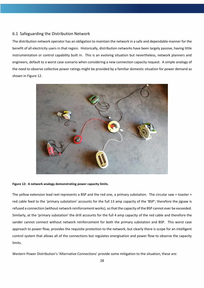
The distribution network operator has an obligation to maintain the network in a safe and dependable manner for the
benefit of all electricity users in that region. Historically, distribution networks have been largely passive, having little
instrumentation or control capability built in. This is an evolving situation but nevertheless, network planners and
engineers, default to a worst case scenario when considering a new connection capacity request. A simple analogy of
the need to observe collective power ratings might be provided by a familiar domestic situation for power demand as
shown in Figure 12.
Figure 12: A network analogy demonstrating power capacity limits.
The yellow extension lead reel represents a BSP and the red one, a primary substation. The circular saw + toaster +
red cable feed to the ‘primary substation’ accounts for the full 13 amp capacity of the ‘BSP’; therefore the jigsaw is
refused a connection (without network reinforcement works), so that the capacity of the BSP cannot ever be exceeded.
Similarly, at the ‘primary substation’ the drill accounts for the full 4 amp capacity of the red cable and therefore the
sander cannot connect without network reinforcement for both the primary substation and BSP. This worst case
approach to power flow, provides the requisite protection to the network, but clearly there is scope for an intelligent
control system that allows all of the connections but regulates energisation and power flow to observe the capacity
limits.
Western Power Distribution’s ‘Alternative Connections’ provide some mitigation to the situation, these are:
29
• Active network management (ANM)
• Timed connection
• Soft intertrip
• Export limiting
More details of these alternative connection arrangements can be found on WPDs website at
https://www.westernpower.co.uk/connections-landing/connection-offers-and-agreements/alternative-connections.
The assumption under examination by the LEM project is that the distribution network operator could use upward
and downward flex services to better manage power flow on the network. Upward flex increases energy on the
network by turning generation up or load down; downward flex is the reciprocal of this. If enough upward and
downward flex is available to the network operator, it can be used, to a great extent, to alleviate and prevent the
stress events that currently either restrict capacity, cause curtailment or necessitate reinforcement. For instance, in
the case described above (Figure 12), if embedded generation, local to the BSP, could be called upon with certainty,
to provide power directly to the BSP at times when the jigsaw needed to operate, then the jigsaw could be given a
connection without reinforcement to the black cable. Having certainty that the local generation (upward flex) can be
secured is contingent on there being sufficient liquidity in the flex market. Such liquidity will also allow the
procurement of flexibility to be affordable to the users of the electricity system, all of whom will pay for any solution
through their system charges. It is likely that this market based solution would still be backed up by the DNO’s ability
to curtail certain connections using the disconnection equipment now specified in the G99 code.
Managing power flow, either with alternative connections or flexibility services can mitigate against thermal
constraints and to a lesser extent, voltage constraints. Thermal constraints and voltage constraints are two of the
three primary constraints, the third being concerned with fault levels. Fault level constraints are explained as follows:
The network operator must ensure that in the event of a short circuit fault on the network, the instantaneous current
will not damage further assets before the automatic disconnection equipment activates. Simply put, the short circuit
current will be a function of the energy delivery infrastructure that is feeding that point on the network. Therefore,
adding distributed generation, in front of or behind the meter, will reinforce the energy supply to any nearby short
circuit and increase the current that flows during the fault event. Before a connection for generation (including
storage) is granted, the contribution to fault currents is assessed and reinforcement might be required. The cost of
such reinforcement, like that of reinforcement necessitated by thermal and voltage stress, is borne by the applicant
requiring the new connection, pro rata to the new additional capacity that is achieved by the incremental upgrade.

30
This type of network constraint cannot be relieved with flexibility and is increasingly becoming an obstacle to both the
connection of zero carbon generation and flexibility such as storage.
6.2 Connections for the Provision of Flexibility
Western Power Distribution’s ‘Alternative Connections’ are a step towards a less passive system but these were
conceived several years ago to accommodate further distributed generation and are not necessarily appropriate for
connections associated with providing flexibility, because:
1. The rules governing the provision of flexibility services to National Grid ESO often require a firm connection
so that there is no obstacle to delivery of the contracted response.
2. The additional equipment that is required with these connections adds significant cost to the applicant.
Whereas these costs might be reasonably absorbed for a generation facility with a high capacity factor and
corresponding revenues, they can become an obstacle to the provision of flex services which might not be
providing the primary revenue stream. Moreover, if the reason for the newly required connection capacity is
to provide services to the network, it seems counter intuitive to discourage such services with expensive
connection offers; rather like a patient charging the nurse to administer medicine to them.
For these reasons, the existing alternative connections are not considered to be the final solution. A solution should
be sought that achieves the requisite protection to the network whilst promoting participation in flexibility services.
This solution might not be technical but might instead use policy, for instance:
A. Remove the necessity of a firm connection from all flexibility services and address the system for non-delivery
penalties accordingly.
B. Socialise the full cost of all connection equipment that is designed to provide network security so that these
costs are met by the DNO and form part of the distribution system costs. This policy reform is, in part, under
discussion.
The ANM system in particular, is the topic of much debate in the wider commentary on flexibility services and
renewable energy generation. Active network management utilises real-time power flow measurement at critical
points on the distribution network to inform curtailment actions at the appropriate connections, so as to protect the
network during stress events. ANM has to date, been used almost exclusively as an option to connect renewables
when the simple analysis described in Figure 12 precludes any additional generation; it is now being offered
occasionally for demand connections.

31
ANM might be considered to be a step towards a fully dynamic, optimised distribution network and indeed the
principle of ‘measure – decide – act’ is sound in this respect. However, the decision and act phases need urgent review.
At the decision stage, the first option should be a flex response as described above. In the case of stress caused by
generation, the solution would be downward flex, ideally achieved by turning useful load up rather than renewables
down; curtailment of much needed zero carbon generation must surely be a last resort action. It should be noted that
flex wouldn’t need to be procured with little or no notice; the predictive capabilities of the network operators is
significant and these stress events can be forecast, unless they result from a sudden network fault. When curtailment
is required, the process is currently governed by the LIFO stack where LIFO is an acronym for Last In First Off; the last
ANM connection approved by the DNO is the first of a group to be curtailed when that group is deemed to be causing
(or about to be causing) unacceptable stress to the system. Considering the national and global requirement for zero
carbon electricity generation, this LIFO system must surely be replaced with a system that doesn’t increasingly penalise
renewable generation as the penetration increases, otherwise the continued and accelerated roll-out of renewables
is at risk of being stifled.
Brief mention of special connection equipment and system costs is made above (B). The G83 and G59 codes that
governed connection of generators to the distribution networks were replaced in 2019 with G98 and G99, G99 being
for generation of more than 16 amps per phase. The G99 code included a new requirement for all generators to be
“equipped with a logic interface (input port) in order to cease Active Power output within 5 s following an instruction
being received at the input port.” This is accompanied by the requirement to agree with the DNO “how the
communication path is to be achieved.” This translates to the imposition of a ‘curtailment panel’ together with some
comprehensive communications equipment such as a microwave link. Essentially, this equipment replicates the
functionality of an ANM connection for every generation connection, in that the DNO now has the capability to curtail
the generation (including storage discharge) at will. In the case referred to in section 4.6, the costs associated with
these new requirements was increased still further by the unrequired addition of ANM infrastructure, creating the
impression that the DNO was now treating every G99 connection as an ANM connection. These curtailment and ANM
equipment costs exceeded £100,000 despite the site not requiring any export capacity for the BTM generation that
would be entirely consumed by the site or nullified by G100 approved, export limitation equipment. The LEM client
felt that this was unreasonable and the LEM team opened a dialogue with Western Power Distribution on their behalf.
The situation was eventually resolved with a renewed connection offer that removed a very significant cost from the
offer, these costs presumably being absorbed by the DNO as system costs. This episode ran concurrently with national
regulatory discussions of a similar theme, held within the Open Networks Project (ONP) and other forums. The ONP
is a multi-year project coordinated by the Energy Networks Association (ENA), which includes all the DNOs, Ofgem and
National Grid. This project is looking at many issues to ensure that distribution networks can actively manage their

32
networks, connect more Distributed Energy Resources (DER) and procure flexibility from market participants. it has
been recognised that the DNOs around the UK are interpreting and applying some G99 requirements in different ways
and that a uniform approach is required. Further to this, it has been signaled that the cost burden of some equipment
associated with system protection, hitherto charged to applicants, will be redefined as a system cost in the future; this
will result in ‘shallow’ connection charges, the term implying that the deeper system costs are socialised through
system charges.
A similar strategy might be more reasonable for all major network reinforcement. If we accept that centralised
systems are being, and must be, replaced with embedded systems (e.g. generation and storage) in the transition
towards net zero, then there is a good argument that large scale reinforcement works such as that contemplated for
the Wave Hub battery system (see Appendix A), should be borne as a system cost. Here, it is the DNO license terms
that need to be updated in line with the decentralisation of our electricity system. Currently, the DNO is required to
bear the cost of upgrades that are necessary to satisfy new demand loads if these loads are operating at two or more
voltage levels, lower than the equipment that needs upgrading. The Wave Hub battery, connecting at 33 kV, must
therefore contribute to the cost of reinforcements required to the 132 kV system whereas a housing development
requiring an 11 kV connection, for instance, would not face these charges. This rationale applied to reinforcement
costs does not take suitable account of flex assets such as batteries which must be recognised as a system need.
Another difficulty encountered with connections during the LEM work was concerned with security of supply.
Engineering Recommendation P2/6 is referenced in the Distribution Code and places a requirement on DNOs to design
their networks such that power supply can be restored to a group of users quickly in the event of any network fault
occurring. Specifically, P2/6 applies to any group of users that have a common network supply path and a total group
demand capacity in excess of 1 MVA. By chance, two of the LEM SGEI projects, Ventonteague wind turbine and Carland
Cross battery, formed a ‘P2/6’ demand group together with the pre-existing Carland Cross Windfarm. The windfarm
had an existing demand capacity of 110 MVA, the Ventonteague wind turbine added 24 kVA and finally the battery
added another 1 MVA, making a total group demand capacity of 1.134 MVA. When WPD assessed the application to
connect the battery, they had to invoke P2/6 according to the Distribution Code and this requirement added cost to
the connection offer. The LEM team requested an exemption from P2/6 in this case, arguing that none of the three
parties forming the group would benefit from the added security. The view we held was that P2/6 was intended to
provide security to energy users on the network rather than renewable generators that occasionally had a small service
load and storage facilities. The request for exemption was declined and WPD managed to identify an economical
solution to satisfy P2/6 requirements for the group. However, this episode again highlights that the regulatory system
33
needs an urgent update to better align to the needs of the electricity system in the light of the climate emergency and
associated UK legal targets.
7. Conclusion
Regulators should act quickly to consider the points raised in the discussions above. It might be necessary to re-write
the terms of the licences that DNOs operate under. The current licence terms were drawn up in an era that preceded
the large-scale roll-out of distributed generation, the decommissioning of centralised generation and the need for
distributed flexibility assets. This might also be accompanied by a review of the distribution code and the codes for
connecting parallel generation to distribution networks. There is a clear need to have a regulatory system that is based
upon distributed renewable energy and the flexibility that will accommodate such a high penetration of intermittent
generation.
The Industrial & Commercial workstream succeeded in stimulating a significant level of activity associated with
renewable energy generation, storage and network connections in Cornwall. The organisations that had contact with
the LEM project, gained an increased understanding of the complexities of operating and balancing the electricity
networks and an appreciation of how flexibility can be used in this respect.
The LEM project team was successful in both achieving the ERDF targets (or achieving an acceptably close outcome)
and investigating flexibility, it’s provision, barriers and the current commercial cases. Recommendations aligned to
the commentary made in this discussions section have been made to the regulators via this project and through
separate consultation processes.
34
Appendix A – Wave Hub 3 MW MIC Budget Estimate
Western Power Distribution Avonbank Feeder Road Bristol BS2 0TB
Our ref Date
3011394 27th March 2018
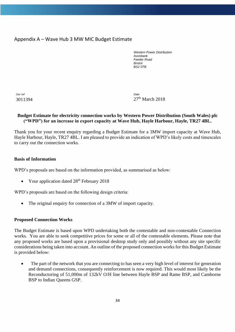
Budget Estimate for electricity connection works by Western Power Distribution (South Wales) plc
(“WPD”) for an increase in export capacity at Wave Hub, Hayle Harbour, Hayle, TR27 4BL.
Thank you for your recent enquiry regarding a Budget Estimate for a 3MW import capacity at Wave Hub,
Hayle Harbour, Hayle, TR27 4BL. I am pleased to provide an indication of WPD’s likely costs and timescales
to carry out the connection works.
Basis of Information
WPD’s proposals are based on the information provided, as summarised as below:
• Your application dated 28th February 2018
WPD’s proposals are based on the following design criteria:
• The original enquiry for connection of a 3MW of import capacity.
Proposed Connection Works
The Budget Estimate is based upon WPD undertaking both the contestable and non-contestable Connection
works. You are able to seek competitive prices for some or all of the contestable elements. Please note that
any proposed works are based upon a provisional desktop study only and possibly without any site specific
considerations being taken into account. An outline of the proposed connection works for this Budget Estimate
is provided below:
• The part of the network that you are connecting to has seen a very high level of interest for generation
and demand connections, consequently reinforcement is now required. This would most likely be the
Reconductoring of 51,000m of 132kV O/H line between Hayle BSP and Rame BSP, and Camborne
BSP to Indian Queens GSP.
35
Appendix A (continued) – Wave Hub 3 MW MIC Budget Estimate
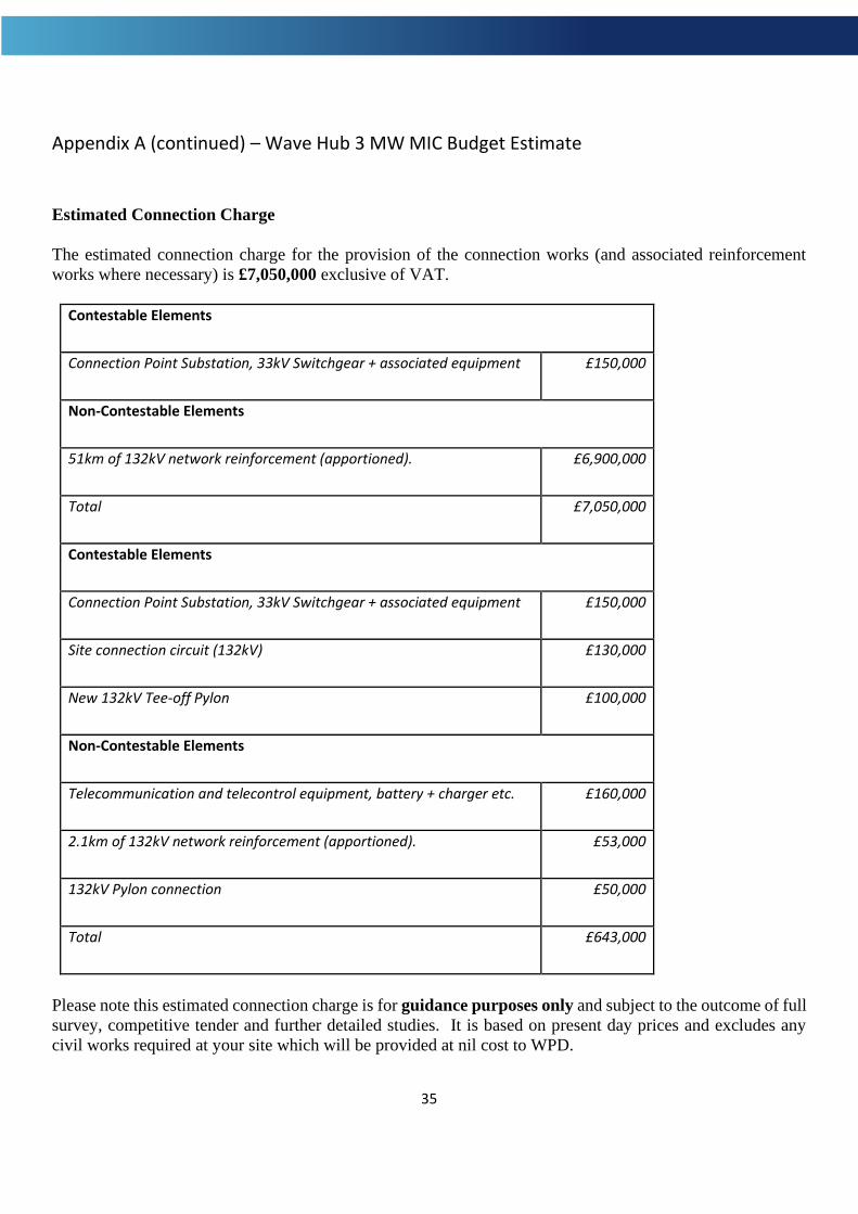
Estimated Connection Charge
The estimated connection charge for the provision of the connection works (and associated reinforcement
works where necessary) is £7,050,000 exclusive of VAT.
Contestable Elements
Connection Point Substation, 33kV Switchgear + associated equipment £150,000
Non-Contestable Elements
51km of 132kV network reinforcement (apportioned). £6,900,000
Total £7,050,000
Contestable Elements
Connection Point Substation, 33kV Switchgear + associated equipment £150,000
Site connection circuit (132kV) £130,000
New 132kV Tee-off Pylon £100,000
Non-Contestable Elements
Telecommunication and telecontrol equipment, battery + charger etc. £160,000
2.1km of 132kV network reinforcement (apportioned). £53,000
132kV Pylon connection £50,000
Total £643,000
Please note this estimated connection charge is for guidance purposes only and subject to the outcome of full
survey, competitive tender and further detailed studies. It is based on present day prices and excludes any
civil works required at your site which will be provided at nil cost to WPD.

36
Appendix A (continued) – Wave Hub 3 MW MIC Budget Estimate
Estimated Timescales
The estimated timescales for the proposed connection works is 24 to 30 months from acceptance of a
Connection Offer and subject to any necessary wayleaves or other consents being successfully obtained.
Statement of Works
Any proposed connection for your site will be subject to the outcome of a Statement of Works (SoW) process
with National Grid Electricity Transmission (NGET). The outcome of this process may increase the above
timescales for connection and increase costs if there are reinforcement works required on NGET’s
transmission network.
For further information relating to NGET restrictions please refer to our website:
www.westernpower.co.uk/docs/connections/Generation/Statement-of-Works
Additional Information
There is further network and capacity information available on our website at www.westernpower.co.uk.
Progression to Offer stage
This Budget Estimate is not legally binding but if you would like WPD to provide a formal Connection Offer
for connection then please forward your application to the address below:
Upon receipt of your full application WPD will carry out detailed network studies to finalise the design of the
connection works (and any associated reinforcement works), and provide a Connection Offer detailing the
works required and the associated costs and timescales.
If you have any queries regarding this Budget Estimate please do not hesitate to contact via the contact details
at the top of this letter.
Yours sincerely,
WPD Primary System Design (South West)