Inductiveloadswitching Standardizationstatus Rene · PDF fileTest duty current capacitance Nr....
48
1 Inductive load switching Standardization status Rene Smeets KEMA Testing, Inspections and Certification The Netherlands Member IEC MT 32 (inductive load switching) IEC 62271-110: Inductive load switching (2005, 1 st edition) � Covers all voltage levels 1 – 800 kV - Unloaded transformer switching (no testing) - Motor switching ≤ 17.5 kV - Shunt reactor switching ≥ 52 kV � Relevant for medium voltage: motor switching - Test-circuit defined in great detail - Three-phase interaction essential - High-frequency phenomena are represented
-
Upload
vuonghuong -
Category
Documents
-
view
218 -
download
5
Transcript of Inductiveloadswitching Standardizationstatus Rene · PDF fileTest duty current capacitance Nr....

1
Inductive load switchingStandardization status
Rene Smeets
KEMA Testing, Inspections and Certification
The Netherlands
Member IEC MT 32 (inductive load switching)
IEC 62271-110: Inductive loadswitching (2005, 1st edition)
� Covers all voltage levels 1 – 800 kV- Unloaded transformer switching (no testing)- Motor switching ≤ 17.5 kV- Shunt reactor switching ≥ 52 kV
� Relevant for medium voltage: motor switching- Test-circuit defined in great detail- Three-phase interaction essential- High-frequency phenomena are represented
2
IEC Test circuit for motor switching
Source Ur Bus representation
Switchgear under test Cable Motor substitute
Ls L R
Rp
Ze Cp
Lb1 Lb2
Cs
IEC 841/05
Supply side capacitance
30 - 50 nF supply circuit A
1.5 – 2 μF supply circuit B
busbar 5-7 m
allowing inductive
coupling between
phases
100 m screened cable
motor model
10 – 15 kHz
oscillating circuit
power factor ≤ 0.2
or actual motor
Required tests
Test duty current capacitance Nr. of tests
1 100 A 30 - 50 nF 20
2 300 A 30 - 50 nF 20
3 100 A 1.5 – 2 μF 20
4 300 A 1.5 – 2 μF 20
20 test at 0.5 ms steps of arcing time (at 50 Hz)
80 tests all together

3
438 440 442 444 446 448 450-50
0
50
100
scale: voltage in kV, current A/10
438 440 442 444 446 448 450-50
0
50
100
438 440 442 444 446 448 450-50
0
50
100
Motor switching test-duty 2, 300 A, no re-ignition
Example of 12 kV VCB (1) + arrester
Phase 1
transient recovery voltage
Phase 2
Phase 3
max. voltage across CB
current
2
3
4
5
6
7
8
9
10
1.0 1.5 2.0 2.5 3.0 3.5 4.0 4.5
pea
k va
lue
of
TRV
(p
u)
arcing time (ms)
TD1
TD3
TD4
TD2
no reignitions
highest level, voltage increased by current chopping
minimum level without currentchopping
� 44% of tests with
minor chopping
overvoltages only
� max. 3.5 pu (34 kV)
across CB
voltage across CB (pu)
arcing time (ms)

4
434 436 438 440 442 444 446-50
0
50
100
scale: voltage in kV, current A/10
434 436 438 440 442 444 446-50
0
50
100
434 436 438 440 442 444 446-50
0
50
100
12 kV VCB (2): Multiple re-ignition
Motor switching test-duty 2, 300 A, muliple re-ignition
436.4 436.6 436.8 437 437.2 437.4 437.6
-20
-10
0
10
20
30
40
50
60
70
438 440 442 444 446 448 450-50
0
50
100
scale: voltage in kV, current A/10
438 440 442 444 446 448 450-50
0
50
100
438 440 442 444 446 448 450-50
0
50
100
TRV to 97 kV in 12 kV system = 10 pu
virtual current chop at 237 A
multiple reignition
Motor switching test-duty 2, 300 A, multiple re-ignition and virtual current chopping generating huge overvoltage
12 kV VCB (3): MR + virtual chopping
virtual current chopping at 237 A

5
2
3
4
5
6
7
8
9
10
1.0 1.5 2.0 2.5 3.0 3.5 4.0 4.5
pea
k v
alu
e o
f TR
V (
pu
)
arcing time (ms)
TD1
TD3
TD4
TD2
no reignitions
� 56% of tests have
multiple re-ignition,
often followed by virtual
current chopping
� max. 9.9 pu (97 kV)
across CB
� TD 2 most severe:
larger current allows
larger virtual chopping
� Large supply side
capacitance (TD3, 4)
reduces transients
� Load voltage limited by
arrester in CB
voltage across CB (pu)
arcing time (ms)
438 440 442 444 446 448 450-50
0
50
100
scale: voltage in kV
438 440 442 444 446 448 450-50
0
50
100
438 440 442 444 446 448 450-50
0
50
100
12 kV VCB (3): MR + virtual chopping
load side voltages limited by arrester
3.4 pu max voltage at virtual chop

6
Conclusions / remarks
� Current chopping is no problem� Multiple re-ignition generate steep surges that
may endanger winding� Virtual chopping is common but can be dealt
with by arrester� Overvoltages in test-circuits are expected to be
higher than in service� There is no limit of overvoltages set in the IEC
standard� Only outside flash-over would prevent VCB
from passing motor switching test� IEC standard not adapted to VCB application
Future standardization in IEC
� New edition of IEC 62271-110 (inductive loadswitching) in 2013
� Shunt reactor switching re-introduced also in voltage range 12 – 52 kV
� Short-circuit duties T10 & T30 will cover providedthat their TRV covers inductive load TRV
� Criterion to pass: re-ignitions at one current zero only
Test duty Nr. of breaking operations current
3 phase 1 phase
1 20 20 1600 A
2 20 20 500 A
3 - 18 500 A
7
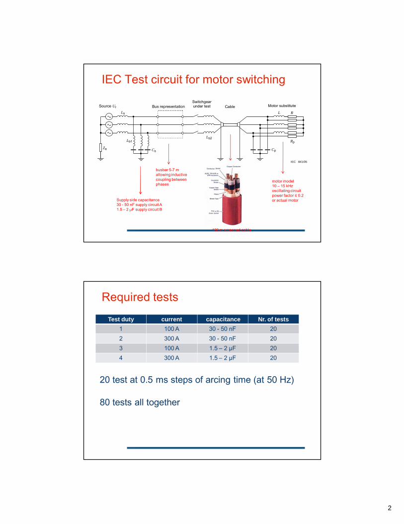
frequent re-ignition no longer allowed
-400
-200
0
200
400
-400
-200
0
200
400
50 55 60 65 70 75 80
-400
-200
0
200
400
criterion 6.115.11a) fulfilled
criterion 6.115.11a) not fulfilled
criterion 6.115.11a) not fulfilled
OK
OK
NOK
Market penetration of vacuum switchgear

8
End sheet
Thank you for your attention.

10-9-2012
1
Transient Processes at Vacuum Circuit Breaker
Switchings and Development of Technical
Requirements for 6-35 kV Vacuum Circuit Breakers
Artem Bazavluk
Senior Engineer of Research Department
LLC BOLID, Novosibirsk, Russia
1
2

10-9-2012
2
Damages at VCB switchings
Motors
XLPE-cables and terminals
Transformers
Current-Limiting Reactors
3
4
Phase(B)-to-phase(C) voltage is 120 kV
Distance between B and C poles is 165 mm
Transient processes at 35 kV VCB switching
14 kV/div
14 kV/div
20 ms/div
0.1 ms/div

10-9-2012
3
Damage of 35 kV VCB (Koksovaya Substation, Nizhny
Tagil Steel Plant)
5
Damage of cable terminal at 35 kV VCB switching
(Koksovaya Substation, Nizhny Tagil Steel Plant)
6

10-9-2012
4
Transient processes at 12.5 MW motor switching
7
0.02 ms/div
Damage of current limiting reactor at VCB closing
8

10-9-2012
5
Measuring Equipment of LLC BOLID
Up-to-date measuring
equipment and own-
constructed devices allow
recording transient processes
with high sampling rate in
the broad range of time
4
Overvoltages at VCB switchings
Overvoltages due to
current chopping
Overvoltage
escalation with high-
frequency restrikes
at VCB opening
Overvoltage
escalation with high-
frequency prestrikes
at VCB closing
Overvoltages due to
virtual current
chopping
5

10-9-2012
6
Current chopping and overvoltage limitation by
overvoltage suppressors
Ichop=2.7…5.0 A
K=2.50…2.54 p.u.
6
5 A/div 0.4 ms/div
4.1 kV/div 0.2 ms/div
Overvoltage escalation with high-frequency restrikes at
VCB opening in the 10-kV network
К=5.75 p.u.
n=23
Uchop=93.5 kV (9.64 p.u.)
7
20.5 kV/div 0.2 ms/div

10-9-2012
7
Multiple restrikes due to contact
bouncing at VCB closing
8
0.05 ms/div4 kV/div
High-frequency overvoltages with prestrikes
at VCB closing
9
0.1 ms/div4 kV/div

10-9-2012
8
Growth of defects in XLPE cable insulation under the
application of high-frequency voltage
Dependence of electric strength Emaх at the end of
the needle electrode corresponding to the
beginning of water treeing growth on the
frequency f for XLPE-insulation
When suddenly injecting energy into solid dielectric material, bond rupture between molecules of carbon and hydrogen in points of higher electric strength E occurs
11
Treeing growth in XLPE cable insulation
Water treeing “fantail”-type which grows
from the needle-type edge on the
semiconducting screen
Water treeing “butterfly”-type which
grows in insulation depth with the center
in the point of local inhomogeneity
12
10-9-2012
9
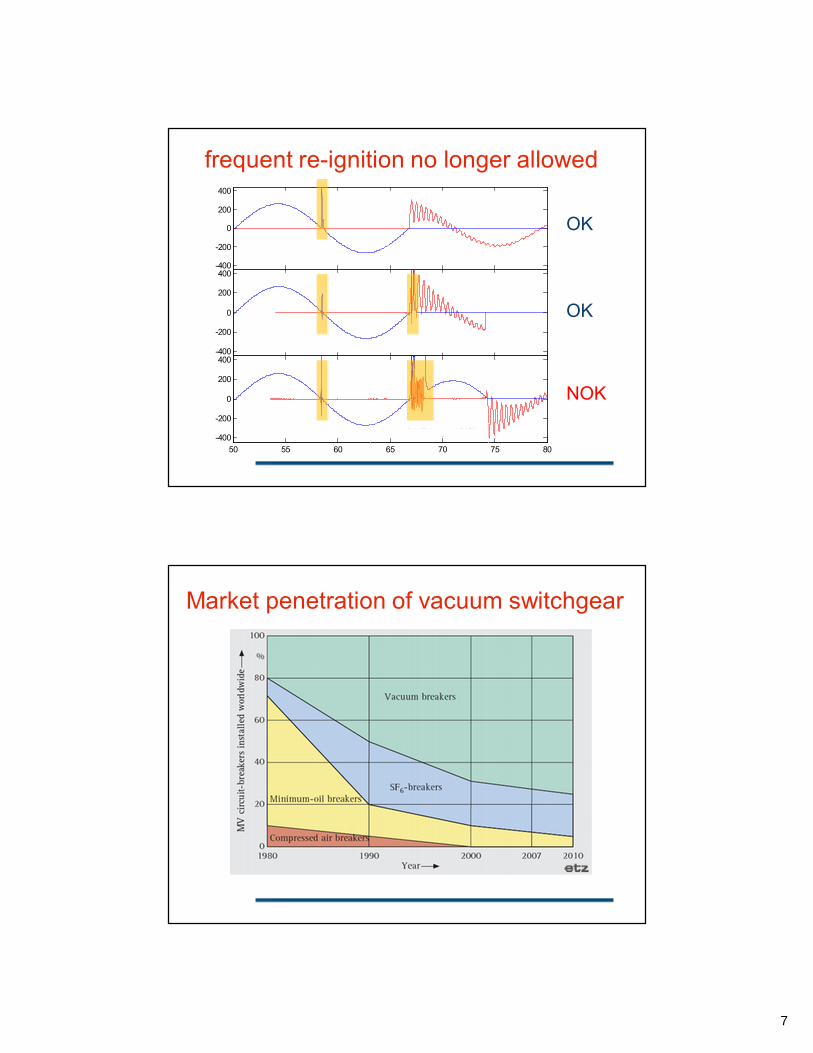
Contact closure velocity versus time for various VCBs
13
Russian circuit breakers Foreign circuit breakers
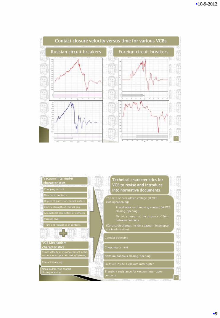
Chopping current
Material of contacts
Degree of purity for contact surface
Electric strength of contact gap
Geometrical parameters of contacts
Vacuum level
Transient resistance of contacts
Vacuum Interrupter
characteristics:
Travel velocity of moving contact in the
vacuum interrupter at closing/opening
Contact bouncing
Nonsimultaneous contact
closing/opening
VCB Mechanism
characteristics:
Technical characteristics for
VCB to revise and introduce
into normative documents
The rate of breakdown voltage (at VCB
closing/opening)
Travel velocity of moving contact (at VCB
closing/opening);
Electric strength at the distance of 2mm
between contacts
(Corona discharges inside a vacuum interrupter
are inadmissible)
Contact bouncing
Chopping current
Nonsimultaneous closing/opening
Pressure inside a vacuum interrupter
Transient resistance for vacuum interrupter
contacts14

10-9-2012
10
Vacuum circuit breakers should be carefully verified and monitored by both manufacturers
and operating companies
Vacuum circuit breakers should be equipped with a special device for controlling and
checking of their mechanical characteristics
VCB characteristics should be periodically checked during their operation
Switched equipment should be protected by overvoltage suppressors and RC-circuits (i.e.
valid choice of VCB and devices for their protection depending on consumer loads)
XLPE cables, motors and transformers should switched by vacuum circuit breakers with
higher technical requirements
GOST requirements should not be applied for all types of vacuum circuit breakers. New
power engineering equipment calls for additional requirements and strengthens existing
requirements
Conclusions
15
16

10-9-2012
11
Recovering of electric strength in different mediums
Recovering of electric strength for 6mm gap after 1600 A interruption in vacuum and various gases under atmospheric pressure

1
© ABB Group September 10, 2012 | Slide 1
Overvoltages generated by VCBsBasics of Inductive Switching
Edgar Dullni, DECMS-ET, 2012-09-04
© ABB Group September 10, 2012 | Slide 2
Overview
� Breaking of inductive currents
� Chopping of current and associated over-voltage
� Over-voltage produced by multiple re-ignitions
� Making of inductive currents
� High-frequency making current
� Pre-ignitions and associated over-voltage
� Virtual chopping
� Mitigation means
2
© ABB Group September 10, 2012 | Slide 3
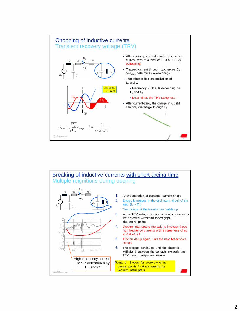
Chopping of inductive currentsTransient recovery voltage (TRV)
� After opening, current ceases just before current-zero at a level of 2 - 3 A (CuCr) (Chopping)
� Trapped current through L0 charges C0
>> Ichop determines over-voltage
� This effect exites an oscillation of L0 and C0
� Frequency > 500 Hz depending on L0 and C0
� Determines the TRV steepness
� After current-zero, the charge in C0 still can only discharge through L0
�
UN
CBC0~
Lz
L0
Lp1
Cz
Lp2Us
I
UN
t
cp
Us
Chopping current
002
1
CLf
��chopi
C
LU ��
0
0max
© ABB Group September 10, 2012 | Slide 4
Breaking of inductive currents with short arcing timeMultiple reignitions during opening
1. After seapration of contacts, current chops
2. Energy is trapped in the oscillatory circuit of the load (L0 - C0)
The voltage at the transformer builds up
3. When TRV voltage across the contacts exceeds the dielectric withstand (short gap),the arc re-ignites
4. Vacuum interrupters are able to interrupt these high frequency currents with a steepness of up to 200 A/µs !
5. TRV builds up again, until the next breakdown occurs
6. The process continues, until the dielectric withstand between the contacts exceeds the TRV >>> multiple re-ignitions
Points 1 – 3 occur for every switching device, points 4 - 6 are specific for vacuum interrupters
High-frequency current peaks determined by
Lp1 and C0
UN
CBC0~
Lz
L0
Lp1
Cz
Lp2Us

3
© ABB Group September 10, 2012 | Slide 5
Range of inductive currents and TRV values
Transformerpower
Primary inductance
Inductive current
Rate of voltage rise
TRV frequency
0.2 – 2 MVA no-load 50 – 1000 H 0.1 - 1 A < 50 V/µs < 0.5 kHz
5 – 20 MVA no-load 5 – 20 H 2 - 10 A > 100 V/µs > 1 kHz
400 kVA induct. load ~ 1 H ~ 20 A 0.5 - 2 kV/µs 4 kHz
10 MVA short-circuit 3 mH 6 kA 4 kV/µs 40 kHz
Voltage rise with VI contact stroke: 30 to 60 V/µs
Voltage withstand at small strokes: 20 to 40 kV/mm
© ABB Group September 10, 2012 | Slide 6
Making of inductive currentsHigh-frequency inrush currents
UN
CBC0~
Lz
L0
Lp1
Cz
Lp2Us
� After contact making, the charge on the cable capacitance Cz discharges into C0
via the cable inductances Lp1 and Lp2
� Frequency of > 400 kHz
� similar to the switching of very small back-to-back capacitors
� In addition the inrush current of the transformer flows, however, on a 50 Hz time scale (10 – 12 x rated current)
C0 consists of the capacitance of the load-side connection, but
also of any earth capacitance of the transformer
1
0ˆˆp
sre L
CUI ���
10
1
2
1
pre LC
f�
���
for Cz >> C0 and Lp1 >> Lp2

4
© ABB Group September 10, 2012 | Slide 7
Making of inductive currentsMultiple re-ignitions during closing
1. Before mechanical touch of contacts, a pre-ignition occurs at small contact gap
2. The source-side cable capacitance instantaneously charges the load–side capacitance C0 and a high-frequency current flows
3. Vacuum interrupters are able to interrupt these high frequency currents with a steepness of up to 200 A/µs !
4. As during the breaking process, a TRV builds up at the transformer terminals.
5. When the TRV exceeds the dielectric withstand of the gap, an arc ignites
6. The process continues until the contacts mate
Main : Graphs
0.0850 0.0860 0.0870 0.0880 0.0890 0.0900 ... ... ...
-20.0
-15.0
-10.0
-5.0
0.0
5.0
10.0
15.0
20.0
Vol
tage
acr
oss
CB
(kV
)
UfeederCBa UfeederCBb UfeederCBc UholdCB -UholdCB
UN
CBC0~
Lz
L0
Lp1
Cz
Lp2Us
© ABB Group September 10, 2012 | Slide 8
Breaking of inductive currents in 3-phase networksVirtual chopping
Load breaking: 400 kWCurrent: 20 AVoltage peak: 97 kVdu/dt (breakdown) 250 kV/µs

5
© ABB Group September 10, 2012 | Slide 9
Virtual chopping through capacitive coupling Exacerbates over-voltages
Return current forces current-zero of 50Hz
currents in other phases >>> virtual chopping
Re-ignition current takes return path through
other phases
�
� Load capacitance�� Source capacitance�
At re-ignition of TRV, the source-side capacitance
charges the load–side cable
© ABB Group September 10, 2012 | Slide 10
Over-voltage probability and mitigation Thesis Helmer, 1996 TU Brunswick
Breaking ofStationary no-load
currentInrush current
Without cable
without ZnO 7.2 pu (80%) 8 pu (30%)
with ZnO 7.5 pu (70%) 7.6 pu (50%)
with ZORC (0 %) (0 %)
80m cable
with ZnO (0 %) 6.2 pu (30%)
� Type A over-voltage in p.u. under different conditions (7.5 p.u. equals BIL)
� Tests on an 11kV / 1 MVA dry type transformer
� Figures in brackets give the probability of occurrance of multiple re-ignitions for an arcing time of < 0.5 ms.
ZORC snubber circuit
Damping by resistor
Surge arresters can limit the peak voltage but cannot prevent multiple re-ignitions


1
Infrastructure & Cities Sector© Siemens AG 2012
Recommended protection for medium voltage motors used with vacuum interrupters
Dr. Erik Taylor
Infrastructure & Cities SectorFolie 2 © Siemens AG 2012
General recommendations for motor switching
• B.K. Gupta (Ontario Hydro), N.E. Nilsson (Ohio Edison), D.K. Sharma (EPRI), “Protection of Motors Against High Voltage Switching Surges,” IEEE Trans. Energy Conversion, vol. 7, no. 1, pg. 139, March 1992.
• “This paper reviews the results from an extensive EPRI project on turn insulation capability of motors and other publications in order to quantify the surge environment and the surge strength of typical utility motors…”
• “The risetimes and magnitudes of surges produced by vacuum and air-magnetic switchgear are similar…”
• “Inadequate quality control appears to be the real cause for low surge strength of poor motors…”
• “Experimental and analytical investigations indicate that modern vacuum switchgear, when used as recommended by the manufacturers, are as benign as air-magnetic switchgear for typical utility applications. In most motor applications with well designed motor supply systems, surge capacitors are not necessary; they may be required only under special circumstances…”
• “As part of the EPRI project, surges at 39 motors in 16 plants of 11 North American utilities were measured over a period of 3 years.”
2
Infrastructure & Cities SectorFolie 3 © Siemens AG 2012
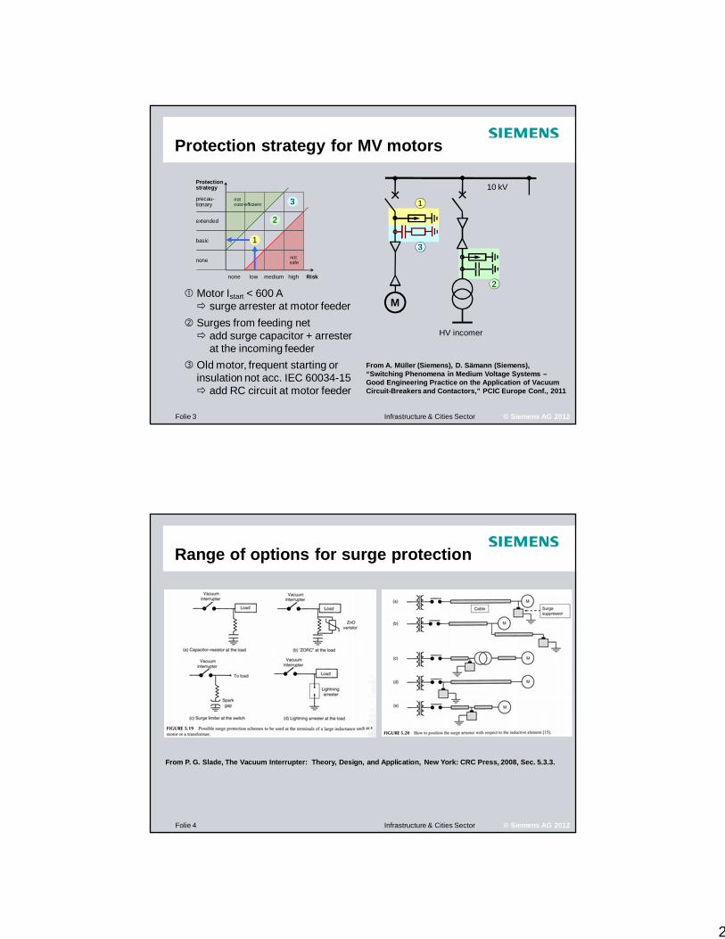
Protection strategy for MV motors
Risk
Protectionstrategy
precau-tionary
extended
basic
none
none low medium high
not safe
notcost-efficient 1
3
2� Motor Istart < 600 A
� surge arrester at motor feeder
� Surges from feeding net� add surge capacitor + arrester
at the incoming feeder
� Old motor, frequent starting or insulation not acc. IEC 60034-15� add RC circuit at motor feeder
10 kV
M
HV incomer
1
2
3
From A. Müller (Siemens), D. Sämann (Siemens), “Switching Phenomena in Medium Voltage Systems –Good Engineering Practice on the Application of Vacuum Circuit-Breakers and Contactors,” PCIC Europe Conf., 2011
Infrastructure & Cities SectorFolie 4 © Siemens AG 2012
Range of options for surge protection
From P. G. Slade, The Vacuum Interrupter: Theory, Design, and Application, New York: CRC Press, 2008, Sec. 5.3.3.
3
Infrastructure & Cities SectorFolie 5 © Siemens AG 2012
Summary
• Well established recommendations for controlling the effect of vacuum interrupter switching surges on MV motors.
• Extensive, multi-year independent study found vacuum switchgear fully compatible with MV motors.
• There are particular situations where surge protection is recommended, and these are well characterized.
• Wide range of protection options and possible locations, extensively discussed in the technical literature.
• Vacuum interrupters for motor switching is fully accepted in the market.
1

2

3
4
5

6

10-9-2012
1
Panel Discussion“Overvoltages generated by VCB
at switching of inductive loads”
Dr. Alexey Chaly
ISDEIV Tomsk · 2—7 September 2012
Excellence in engineering
Statement №1
[1] “Overvoltages at vacuum circuit breakers switching”, EnergoExpert, vol. 2, 2011
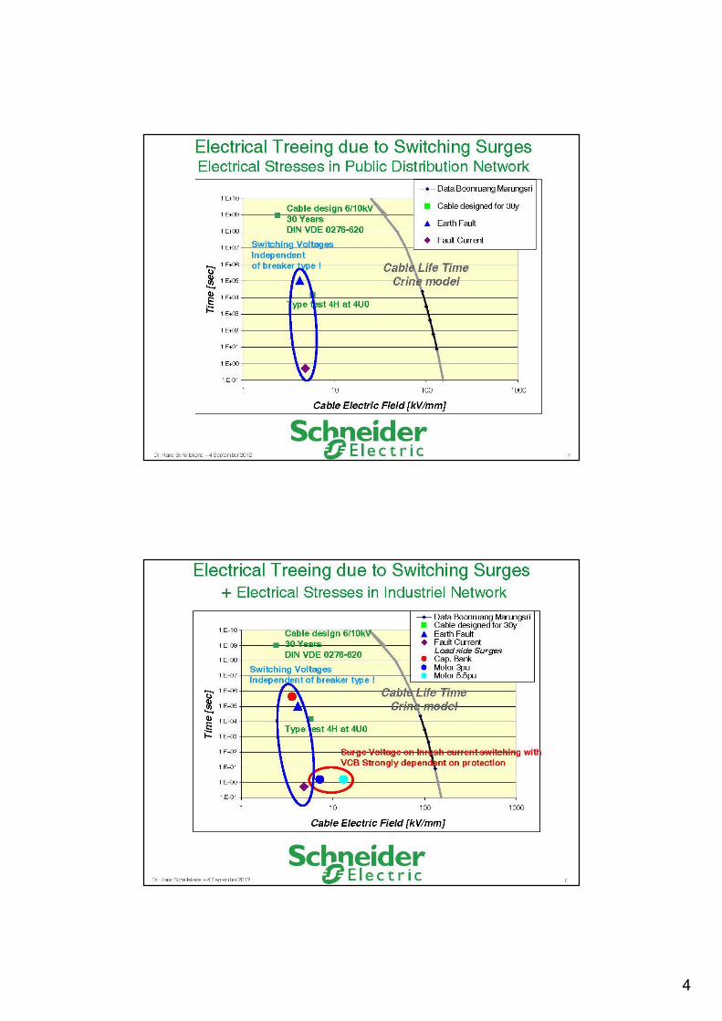
“Deployment of VCB into electrical networks of ore factories resulted in growth of earth faults stimulated by switching overvoltages” [1]

10-9-2012
2
Investigation of the only available reference [2]
shown the following:
— author claims that percentage of earth faults due to switching overvoltages increased
[2] Faults Investigations at electrical network of ore factories,News of Electrical Technology, vol. 5 (60), 2010
This claim is not supported with any primary data
This claim is not supported with any methodology:
— What type of VCB was used?
— Was overvoltage protection applied?
— How different reasons of overvoltages have been discriminated?
Failure cause Weight, %
before 2002 2002—2008
Lightning overvoltages 5 4
Earth fault overvoltages 25 33
Switching overvoltages 10 38
Aging of the insulation 54 20
Mechanical stress 2 3
Other cause 4 2
Percentage of failure cause

10-9-2012
3
[3] Decree from JSC “Kuzbassenergo” from 22.10.2010[4] Response from JSC “Kuznetskiy ferroalloy”, 2012[5] Response from JSC “Iskitimcement”, 2012
Our direct inquiry to ore factories revealed the opposite situation. Chief power engineers of the factories do not notice increase of damages of insulation due to switching overvoltages after deployment VCB into their network [3, 4, 5]
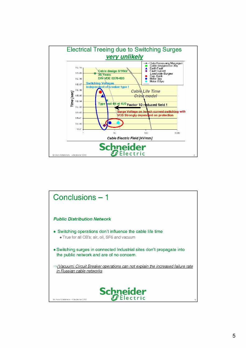
Conclusion №1
Reliable field data proving that deployment of VCB into ore factories resulted in increase of insulation damages due to switching overvoltages has not been presented in the only available reference.

10-9-2012
4
Statement №2
[2] Faults Investigations at electrical network of ore factories,News of Electrical Technology, vol. 5 (60), 2010
[6] Scientific and technical report: experimental research of vacuum circuit breakers characteristics during motor switching at Novosibirskaya CHPP №4, 2010
This was stated on the basis of experimental investigation conducted in [6] at which 3 types of VCB and 1 OCB were closed 10 times each for motor 800kW connected with approximately 100 m cable.
“VCB creates higher overvoltagesthan OCB at motor closing” [2, 6]
Investigated CB
Switchgear 6 kV
Busbar 9PA
Reserve CB
Voltagedivider
Voltagedivider
Voltagedivider
Oscillographs DL-750
CT Shunt
Motor
10-9-2012
5
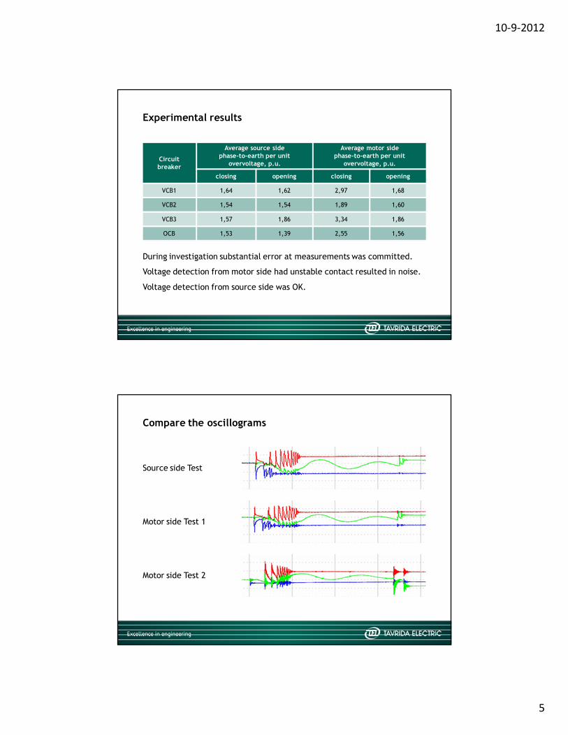
During investigation substantial error at measurements was committed.
Circuitbreaker
Average source sidephase-to-earth per unit
overvoltage, p.u.
Average motor sidephase-to-earth per unit
overvoltage, p.u.
closing opening closing opening
VCB1 1,64 1,62 2,97 1,68
VCB2 1,54 1,54 1,89 1,60
VCB3 1,57 1,86 3,34 1,86
OCB 1,53 1,39 2,55 1,56
Experimental results
Voltage detection from motor side had unstable contact resulted in noise.
Voltage detection from source side was OK.
Motor side Test 1
Motor side Test 2
Source side Test
Compare the oscillograms

10-9-2012
6
Ratio of the maximum motor side overvoltagesto the source side overvoltages
What is average overvoltage for this oscillogram?
Then why average is so important for insulation?
For insulation we would expect maximum overvoltage tobe more important.
10-9-2012
7
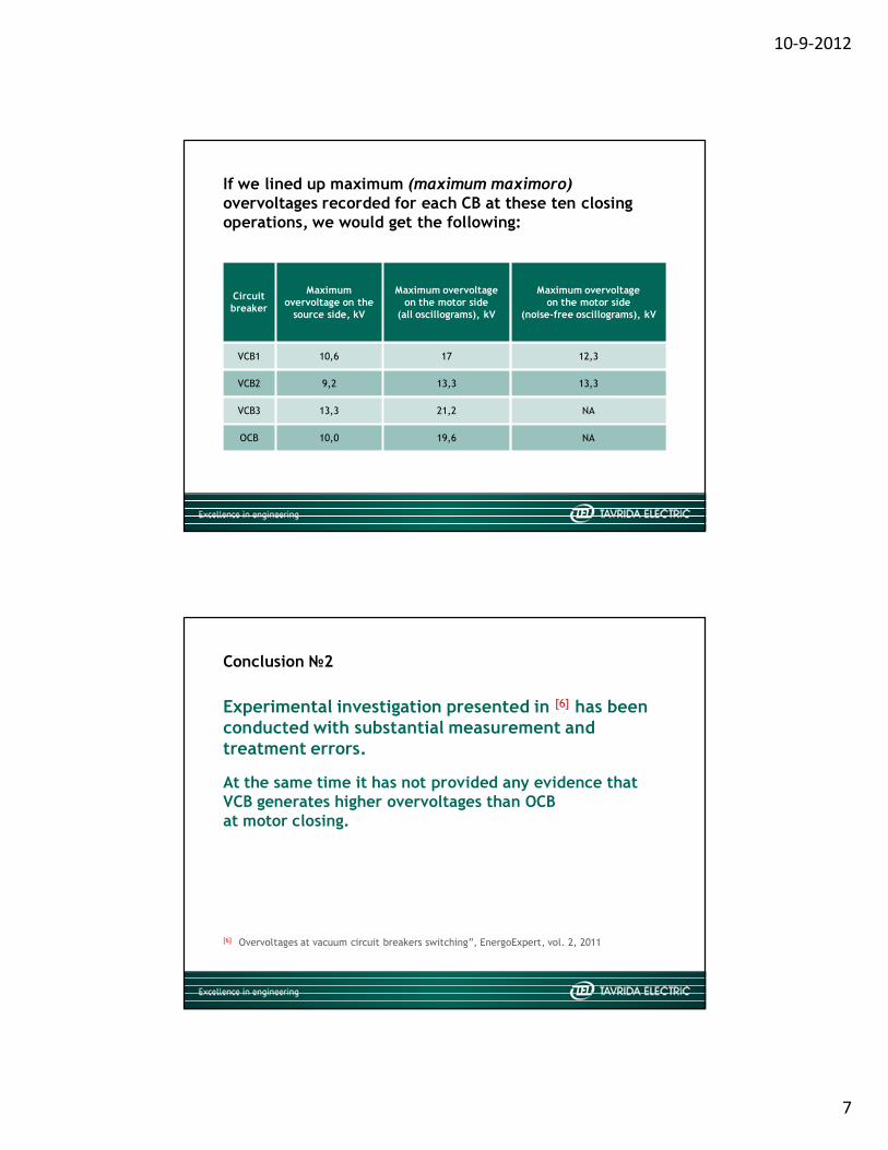
Circuit breaker
Maximumovervoltage on the
source side, kV
Maximum overvoltageon the motor side
(all oscillograms), kV
Maximum overvoltageon the motor side
(noise-free oscillograms), kV
VCB1 10,6 17 12,3
VCB2 9,2 13,3 13,3
VCB3 13,3 21,2 NA
OCB 10,0 19,6 NA
If we lined up maximum (maximum maximoro) overvoltages recorded for each CB at these ten closing operations, we would get the following:
Conclusion №2
[6] Overvoltages at vacuum circuit breakers switching”, EnergoExpert, vol. 2, 2011
At the same time it has not provided any evidence that VCB generates higher overvoltages than OCBat motor closing.
Experimental investigation presented in [6] has been conducted with substantial measurement and treatment errors.

10-9-2012
8
Statement №3
[1] Overvoltages at vacuum circuit breakers switching”, EnergoExpert, vol.2, 2011
“To ensure safe VCB operation (from overvoltage generation standpoint) the following additional requirements shall be applied for VCB. Foreign VCB can meet all these requirements but none of the local manufacturers can meet all of them” [1]
Parameter Value
Non-simultaneity of main contacts closing, milliseconds, not more 1
Non-simultaneity of main contacts opening, milliseconds, not more 1
Contact velocity at closing, m/s, not less 1,2
Contact velocity at opening, m/s, not less 1,5
Contact bounce duration, ms, not more 0
Contact resistance, micro Ohm, not more 40
Current chopping, A 3,5-5
VI pressure, Pa, not more 10e-4
Duration of repeatable breakdowns, microseconds, not more 50
VI dielectric strength at 2mm contact gap, kV/mm, not less 35
Breakdown voltage reduction rate at closing, kV/ms, not less 60
Breakdown voltage increment rate at opening, kV/ms, not less 75
Additional VCB requirements
10-9-2012
9
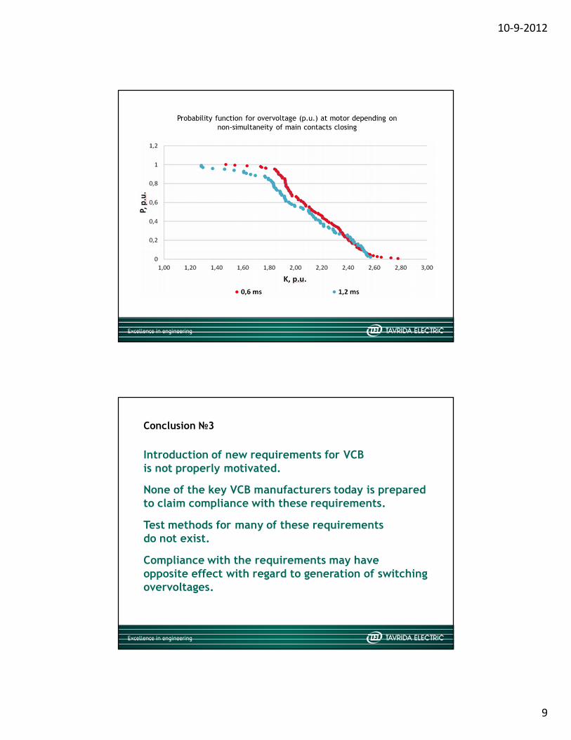
Probability function for overvoltage (p.u.) at motor depending onnon-simultaneity of main contacts closing
Conclusion №3
None of the key VCB manufacturers today is prepared to claim compliance with these requirements.
Test methods for many of these requirementsdo not exist.
Compliance with the requirements may haveopposite effect with regard to generation of switching overvoltages.
Introduction of new requirements for VCBis not properly motivated.

10-9-2012
10
Statement №4
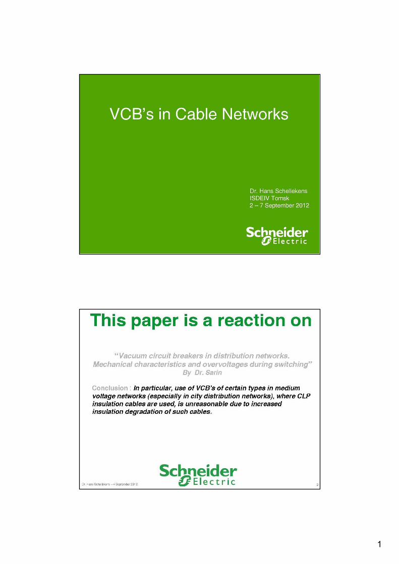
[7] Vacuum circuit breakers in distribution networks.Mechanical characteristics and overvoltages during switching, Progress electro, 2010
“Preferable CB for distribution networks are oilor SF6 circuit breakers” [7]
Conclusion №4
This statement is false as authors have not presented any proof that VCB being properly protected in accordance with the manufacturers recommendation generates more dangerous overvoltages than oil or SF6 circuit breakers.

10-9-2012
11
Maximum switching-on overvoltage mode for ideal CB (0,8 MVA motor, 100 m cable, 5 kV/div, 100 us/div)
Tavrida vision related to VCB application for motor closing
The most dangerous regime is associated with the closure of the first CB pole at voltage maximum followed by closure of the second and third poles in the opposite maximum of the motor natural frequency oscillation.
Closing of motors for any breaker results in switching overvoltages.
In this regime for ideal CB (not capable of interrupting HF currents) maximum overvoltages may reach 3.3 p.u. unipolar [8] (at motor terminals) that is below requirements of IEC 60034-15 (4.9 p.u for 6kV motors) with safety margin 33%.
[8] Numerical Simulation of Overvoltage Generated at Switching on Medium-voltage Motors with the aid of Different Circuit Breakers, ISDEIV Paper, 2012
[9] Switching phenomena in medium voltage systems good engineering practice on the application of vacuum circuit breakers and contactors, PCIM Europe Paper RO-47, 2011
At the same time bipolar voltage may reach 4.9 p.u. that will result for typical motor in 3.2 (65%) p.u. interturn voltage [9]. This is still below insulation level prescribed in IEC 60034-15 (3.9 p.u. for 6 kV motors) with safety margin 18%.
Closing of vacuum circuit breakers is associated with the multiple restrikes that is not advantageous for insulation. From the other hand these restrikes have positive effect of limiting maximum overvoltages to lower level than for ideal breaker (<2.8 p.u. with 99% probability) [8]

10-9-2012
12
Conclusion for motor closing
At the same time we cannot claim that closing of CB (of any type) is 100% safe for Russian market as GOST does not prescribe any requirements related to motor impulse withstand capability.
We consider overvoltage effect of different CB at motor closing as approximately equal and not dangerous from IEC 60034-15 standpoint.
Tavrida vision related to VCB applicationfor motor interruption
It seems that today there is a common vision that the most dangerous regime is interruption of starting motor that is rare or irrelevant for majority of applications.
[10] The influence of a vacuum circuit breaker and circuit parameters of switching overvoltages generated during interruption of starting motors, ISDEIV Paper, 1996[11] Voltage escalation in the switching of the motor control circuit by the vacuum contactor,
IEEE TRANS. PAS Vol. 91, 1972
On the other hand in this regime if VCB starts departing contacts close to natural current zero dangerous overvoltages may be generated for a wide range of motor powers and cable lengths [10].
This process first discovered in early 70-s and called «Voltage escalation» [11]
is relevant only for breakers having high HF interrupting performance, i.e. VCB.
10-9-2012
13
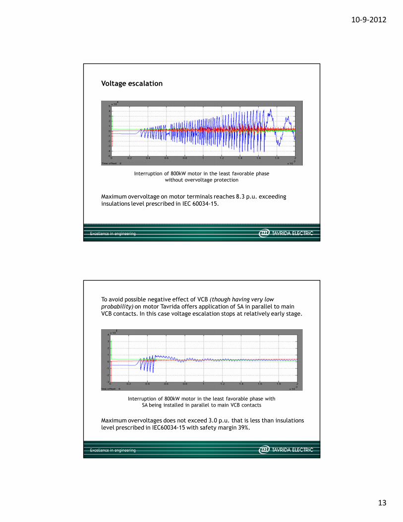
Interruption of 800kW motor in the least favorable phasewithout overvoltage protection
Voltage escalation
Maximum overvoltage on motor terminals reaches 8.3 p.u. exceeding insulations level prescribed in IEC 60034-15.
To avoid possible negative effect of VCB (though having very low probability) on motor Tavrida offers application of SA in parallel to main VCB contacts. In this case voltage escalation stops at relatively early stage.
Maximum overvoltages does not exceed 3.0 p.u. that is less than insulations level prescribed in IEC60034-15 with safety margin 39%.
Interruption of 800kW motor in the least favorable phase with SA being installed in parallel to main VCB contacts
10-9-2012
14
Conclusion for motor interruption
Resulting maximum overvoltages are also lower than the ones that may be generated by ideal CB at motor closing and by transient earth faults.
To avoid dangerous overvoltages at interruption of starting motors we recommended installation of SA in parallel to main VCB contacts. This limits overvoltages to safe level (from IEC60034-15 standpoint).
Thank you
Excellence in engineering