!['V'x(v,'V'xA)=j · 2020. 4. 28. · the equivalent motor circuit. Finite element analysis (FEA) in induction motors (1M) is a step towards the modern design of induction motors [15]](https://static.fdocuments.us/doc/165x107/5fc782d0c1220c0a070a382a/vxvvxaj-2020-4-28-the-equivalent-motor-circuit-finite-element-analysis.jpg)
Induction Motor Equivalent Circuit for Dynamic...
6
1 Abstract— until now the use of equivalent circuit for induction motor has been limited for steady state analysis. The equivalent circuits for dynamic simulation proposed until now, are not able to obtain the transient response of the induction motor, because they lack of mechanical component representations. Complex non-linear matrices are used instead. Here electrical analogy of mechanical system is integrated with d-q equivalent circuit derivates from the stator frame of reference to create a complete equivalent circuit for three-phase induction motor which is suitable for dynamic simulation. Finally this paper presents results that validate the proposed circuit by comparing it with that obtained with mathematical models. Index Terms—Induction Motor modeling, Dynamic model, Induction Motor simulation. I. INTRODUCTION nduction motors are the preferred electric motor in industrial applications. It is rugged, easy to maintain, low cost and easy starting which made it be better option than synchronous and brushless DC motors in many applications. Usually, equivalent circuits are valuable tools that help to understand and analyze electric machines and have been used for a long time. For example figure 1 shows an equivalent circuit for steady state analysis of induction motors. This model is useful in predicting current, power and torque of the motor. Fig. 1. Steady state equivalent model. However this equivalent circuit cannot be plugged with three phase AC source and obtain the dynamic behavior. As an example, the ripple starting torque and ripple starting speed which play an important role in new control methods (e.g. vector control) where precision speed is required. Figure 2 shows d-q equivalent circuits for the arbitrary frame of reference. These circuits help to understand how the current and voltage of the stator and rotor are related. In order to obtain the dynamic behavior of three-phase induction motor, equations that related the six voltages (stator and rotor) with six current has been developed. Those equations can be written in a six by six matrix and has been analysis in the literature extensively [1]. Using d-q transformation this matrix is reduced to a four by four matrix (for balance systems) with considerable reduction in computation. The d-q new frame of references can be fixed or rotating with respect to the fixed stator winding, (i.e. stator rotor and synchronous flux of this d-q transformation) [2]. This d-q transformation will provide a better understanding of the expected torque. The literature offers the equations and equivalent circuits for any arbitrary frame of reference for the versions previously mentioned [3-5]. Fig. 2. Dynamic or d-q equivalent circuits of an induction machine. Since these equivalent circuits do not include mechanical system in which speed as function of torque can be determined, it cannot be used directly for dynamic simulation. To obtain this dynamic behavior it is necessary to go back to the matrix equations expressed in terms of state equations and solve it in conjunction with mechanical system. This state equations matrix are not linear and time invariant since its terms are function of the angular speed [6]. This drawback and the need to compute the mechanical system made this procedure hard and time consuming. It is the objective of this work is to create an equivalent circuit suitable for dynamic simulation. This equivalent circuit should have only electrical components to emulate the electrical and mechanical behavior of an induction motor, and Induction Motor Equivalent Circuit for Dynamic Simulation Andrés Diaz IEEE Member, Roger Saltares, Christian Rodriguez, Roberto F. Nuñez, Eduardo I. Ortiz-Rivera IEEE Member, Jesús Gonzalez-Llorente I 858 978-1-4244-4252-2/09/$25.00 ©2009 IEEE
Transcript of Induction Motor Equivalent Circuit for Dynamic...

1
Abstract— until now the use of equivalent circuit for induction
motor has been limited for steady state analysis. The equivalent circuits for dynamic simulation proposed until now, are not able to obtain the transient response of the induction motor, because they lack of mechanical component representations. Complex non-linear matrices are used instead. Here electrical analogy of mechanical system is integrated with d-q equivalent circuit derivates from the stator frame of reference to create a complete equivalent circuit for three-phase induction motor which is suitable for dynamic simulation. Finally this paper presents results that validate the proposed circuit by comparing it with that obtained with mathematical models.
Index Terms—Induction Motor modeling, Dynamic model, Induction Motor simulation.
I. INTRODUCTION nduction motors are the preferred electric motor in industrial applications. It is rugged, easy to maintain, low
cost and easy starting which made it be better option than synchronous and brushless DC motors in many applications. Usually, equivalent circuits are valuable tools that help to understand and analyze electric machines and have been used for a long time. For example figure 1 shows an equivalent circuit for steady state analysis of induction motors. This model is useful in predicting current, power and torque of the motor.
Fig. 1. Steady state equivalent model.
However this equivalent circuit cannot be plugged with three phase AC source and obtain the dynamic behavior. As an example, the ripple starting torque and ripple starting speed which play an important role in new control methods (e.g. vector control) where precision speed is required. Figure 2 shows d-q equivalent circuits for the arbitrary frame of reference. These circuits help to understand how the current
and voltage of the stator and rotor are related. In order to obtain the dynamic behavior of three-phase induction motor, equations that related the six voltages (stator and rotor) with six current has been developed. Those equations can be written in a six by six matrix and has been analysis in the literature extensively [1]. Using d-q transformation this matrix is reduced to a four by four matrix (for balance systems) with considerable reduction in computation. The d-q new frame of references can be fixed or rotating with respect to the fixed stator winding, (i.e. stator rotor and synchronous flux of this d-q transformation) [2]. This d-q transformation will provide a better understanding of the expected torque. The literature offers the equations and equivalent circuits for any arbitrary frame of reference for the versions previously mentioned [3-5].
Fig. 2. Dynamic or d-q equivalent circuits of an induction machine.
Since these equivalent circuits do not include mechanical system in which speed as function of torque can be determined, it cannot be used directly for dynamic simulation. To obtain this dynamic behavior it is necessary to go back to the matrix equations expressed in terms of state equations and solve it in conjunction with mechanical system. This state equations matrix are not linear and time invariant since its terms are function of the angular speed [6]. This drawback and the need to compute the mechanical system made this procedure hard and time consuming. It is the objective of this work is to create an equivalent circuit suitable for dynamic simulation. This equivalent circuit should have only electrical components to emulate the electrical and mechanical behavior of an induction motor, and
Induction Motor Equivalent Circuit for Dynamic Simulation
Andrés Diaz IEEE Member, Roger Saltares, Christian Rodriguez, Roberto F. Nuñez, Eduardo I. Ortiz-Rivera IEEE Member, Jesús Gonzalez-Llorente
I
858978-1-4244-4252-2/09/$25.00 ©2009 IEEE

2
be able to work in any electric simulation application.
II. NOMENCLATURE Different variables for motor parameters are defined here: Vqs equivalent stator quadrature voltage Vds equivalent stator direct voltage Rs stator resistance Ls stator leakage inductance Lm magnetizing inductance Lr rotor leakage inductance Rr rotor resistance p derivative operation P poles ωr rotor angular speed in electrical degrees ωc reference frame angular velocity in electrical degrees Iqs stator equivalent quadrature current Ids stator equivalent direct current Iqr rotor equivalent quadrature current Idr rotor equivalent direct current Va phase a to neutral voltage Vb phase b to neutral voltage Vc phase c to neutral voltage Ia phase a line current Ib phase b line current Ic phase c line current
III. MODEL DEVELOPMENT The equivalent circuit for d-q axis is derivate from the voltage and current matrix for the stator frame of reference as shown in (1):
0 0
0 0qs S S m qs
ds s s m ds
qr m r m r r r r qr
dr r m m r r r r
V R L p L p iV R L p L p iV L p wL R L p wL iV wL L p L R L p idrω
+⎡ ⎤ ⎡ ⎤⎡ ⎤⎢ ⎥ ⎢ ⎥⎢ ⎥+⎢ ⎥ ⎢ ⎥⎢ ⎥=⎢ ⎥ ⎢ ⎥⎢ ⎥− + −⎢ ⎥ ⎢ ⎥⎢ ⎥+ ⎣ ⎦⎣ ⎦ ⎣ ⎦
)1(
The equation for Vqs and Vqr can be represented for a circuit equivalent of a transformed where and induced voltage in the secondary is function of the rotor flux and the rotor speed.
)2( qrmqssqssqs piLpilirV ++=
(3) )( drrdrrdrrdsmrqsmqr piLiRiLiLpiLV +++−= ϖ )4( 0 rdrdrrdrrqsm piLiRpiL ψϖ−++=
Figures 3-a and 3-b show the equivalent circuits for the d
axis and q axis
Fig. 3-a. Q-axis of the equivalent circuit.
Fig. 3-b. Q-axis of the equivalent circuit.
Both circuits are coupled by the speed and the voltage induced in the rotor which depend on the opposite axis flux. The flux can be solved using the d-q currents. However speed depends of torque and mechanical parameters. The torque is a function of the product of current and flux of both d-q axes circuits, (5):
( ) )5( 23
qsrddsrq LLTorque ψψ ⋅−⋅⋅=
)6( drmdssds iLiL ⋅+⋅=ψ )7( qrmqssqs iLiL ⋅+⋅=ψ
Finally, speed is a function of torque and mechanical load which is not represented in those circuits. Another circuit is necessary to represent the mechanical part.
IV. MECHANICAL EQUIVALENT CIRCUIT The electric torque is divided by the inertia J of the motor in
order to obtain the angular acceleration. Then it has to be integrated to obtain the angular velocity. The best circuit to represent this integration is a current source feeding a capacitor. While equivalent circuits for q and d axis are AC, this circuit for mechanic system is DC. If the current source value is proportional to the electric torque and the capacitance value is proportional to the motor inertia then the voltage across the capacitor is proportional to the speed. A similar approach have been presented in the past by [7] using electrical analogies to model mechanical components. Figure 3 shows the circuit with the current sources and other elements representing the mechanical system.
C_Jm I_TL
GAIN
TorqueGND
R_Bm
Fig. 4. Mechanical system equivalent circuit
A constant load I_TL is represented as a current source,
which produces a current (load torque) opposed to the electric torque. A frictional load R_Bm which torque is proportional to
859
3
the speed is represented as a resistor. Table 1 shows the equivalence between electrical a mechanical unity that is use to make the conversion between both systems.
Unit Conversion Table Mechanical Parameters Electrical Equivalence
mN ⋅1 1 A 21 mKg ⋅ 1 F
sec1 rad 1 V
Table 1. Equivalence between mechanical and electrical units.
The equivalence between capacitor voltage and rotor
angular speed is corroborated using the following integration:
)8( ∫ ∫ === cr VdtCIdt
JTϖ
The angular speed of the rotor is in rad/sec while the capacitor voltage is in volts. This signal is feedback to the equivalence circuit of the d and q axis to create the voltage generated in the rotor by its own movement. If the motor has more than two poles then the equation of torque and generated voltages has to be multiply by P/2. That remains the other mechanical components as friction load and constant load without change. The resistor and current values of load analogies are selected using (9) and (10):
)9( )()( mNTAI LL ⋅=
)10( )(1)( secmNrad
B BR ⋅⋅=Ω
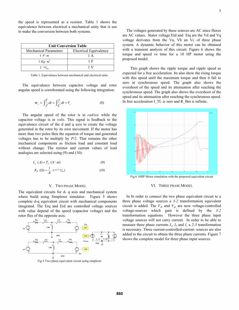
V. TWO PHASE MODEL The equivalent circuits for d- q axis and mechanical system where build using Simplorer simulator. Figure 5 shows complete d-q equivalent circuit with mechanical components integrated. The Erq and Erd are controlled voltage sources with value depend of the speed (capacitor voltage) and the rotor flux of the opposite axis.
LqsRqs RqrLqr
LMq
LdsRds RrdLdr
LMd
C_Jm I_TL
GAIN
GAIN
GAIN
Erd
Torque
Erq
GND
GND
GND
R_Bm
Vq
Vd
Fig 5.Two phase equivalent circuit using simplorer
The voltages generated by these sources are AC since fluxes
are AC values. Stator voltage Etd and Etq are the Vd and Vq voltage derivates from the Va, Vb an Vc of three phase system. A dynamic behavior of this motor can be obtained with a transient analysis of this circuit. Figure 6 shows the torque and speed vs time for a 10 HP motor using the proposed model.
This graph shows the ripple torque and ripple speed as
expected for a free acceleration. Its also show the rising torque with this speed until the maximum torque and then it fall to zero at synchronous speed. The graph also shows the overshoot of the speed and its attenuation after reaching the synchronous speed. The graph also shows the overshoot of the speed and its attenuation after reaching the synchronous speed. In free acceleration I_TL is zero and R_Bm is infinite.
Fig.6 10HP Motor simulation with the proposed equivalent circuit
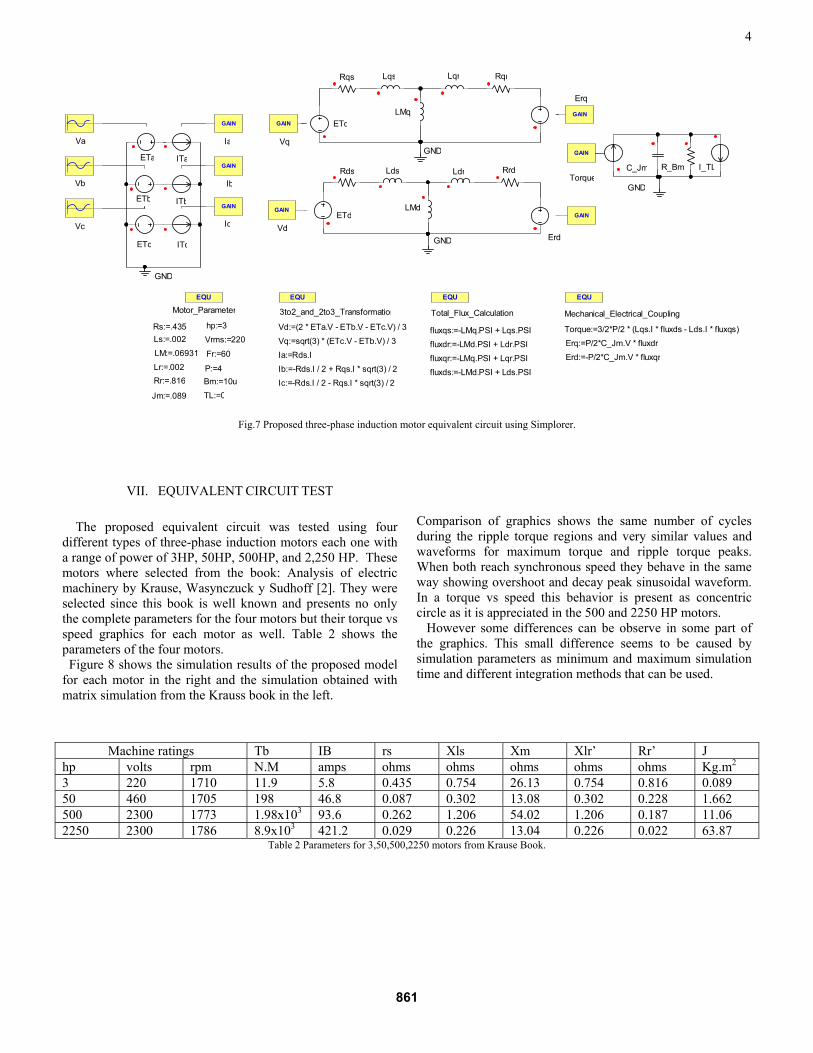
VI. THREE PHASE MODEL In In order to connect the two phase equivalent circuit to a
three phase voltage sources a 3-2 transformation equivalent circuit is added. The Vds and Vqs are now voltage-controlled voltage-sources which gain is defined by the 3-2 transformation equations. However the three phase input voltage sources will not carry current. In order to be able to measure three phase currents Ia, Ib and Ic a 2-3 transformation is necessary. Three current-controlled-current- sources are also added to the circuit to obtain the three phase currents. Figure 7 shows the complete model for three phase input sources.
860
4
ETq
LqsRqs RqrLqr
LMq
ETd
LdsRds RrdLdr
LMd
C_Jm I_TL
EQU
Total_Flux_Calculation
GAIN
GAIN
GAIN
Erd
Torque
Erq
GAIN
Ia
GAIN
Ib
GAIN
Va
Vb
Vc
GAIN
GAIN
Ic
EQU
3to2_and_2to3_Transformation
Vq
Vd
EQU
Mechanical_Electrical_Coupling
GND
GND
GND
GND
Vd:=(2 * ETa.V - ETb.V - ETc.V) / 3Vq:=sqrt(3) * (ETc.V - ETb.V) / 3Ia:=Rds.IIb:=-Rds.I / 2 + Rqs.I * sqrt(3) / 2Ic:=-Rds.I / 2 - Rqs.I * sqrt(3) / 2
ETa
ETb
ETc
fluxqs:=-LMq.PSI + Lqs.PSIfluxdr:=-LMd.PSI + Ldr.PSIfluxqr:=-LMq.PSI + Lqr.PSI
Erq:=P/2*C_Jm.V * fluxdrErd:=-P/2*C_Jm.V * fluxqr
Torque:=3/2*P/2 * (Lqs.I * fluxds - Lds.I * fluxqs)
ITa
ITb
ITc
R_Bm
EQU
Motor_Parameter
Lr:=.002Rr:=.816
Ls:=.002Rs:=.435
LM:=.06931
Jm:=.089
Bm:=10uTL:=0
P:=4
Vrms:=220
Fr:=60
hp:=3
fluxds:=-LMd.PSI + Lds.PSI
Fig.7 Proposed three-phase induction motor equivalent circuit using Simplorer.
VII. EQUIVALENT CIRCUIT TEST
The proposed equivalent circuit was tested using four different types of three-phase induction motors each one with a range of power of 3HP, 50HP, 500HP, and 2,250 HP. These motors where selected from the book: Analysis of electric machinery by Krause, Wasynczuck y Sudhoff [2]. They were selected since this book is well known and presents no only the complete parameters for the four motors but their torque vs speed graphics for each motor as well. Table 2 shows the parameters of the four motors. Figure 8 shows the simulation results of the proposed model for each motor in the right and the simulation obtained with matrix simulation from the Krauss book in the left.
Comparison of graphics shows the same number of cycles during the ripple torque regions and very similar values and waveforms for maximum torque and ripple torque peaks. When both reach synchronous speed they behave in the same way showing overshoot and decay peak sinusoidal waveform. In a torque vs speed this behavior is present as concentric circle as it is appreciated in the 500 and 2250 HP motors. However some differences can be observe in some part of the graphics. This small difference seems to be caused by simulation parameters as minimum and maximum simulation time and different integration methods that can be used.
Machine ratings Tb IB rs Xls Xm Xlr’ Rr’ J hp volts rpm N.M amps ohms ohms ohms ohms ohms Kg.m2 3 220 1710 11.9 5.8 0.435 0.754 26.13 0.754 0.816 0.089 50 460 1705 198 46.8 0.087 0.302 13.08 0.302 0.228 1.662 500 2300 1773 1.98x10³ 93.6 0.262 1.206 54.02 1.206 0.187 11.06 2250 2300 1786 8.9x10³ 421.2 0.029 0.226 13.04 0.226 0.022 63.87
Table 2 Parameters for 3,50,500,2250 motors from Krause Book.
861

5
Fig.8 Motors simulation for 3,50,500and 2250HP:Krause Book left, proposed equivalent circuit right.
862

6
VIII. CONCLUSION A complete novel equivalent circuit for three-phase induction motor has been presented in this paper. Electrical analogies of the mechanical component as friction load, constant load, electric torque and inertia of the motor are used. These components are substituted by two current sources, one capacitor and one resistor. Electrical and mechanical systems are coupled using voltage and current controlled sources. The results are shown to be the same obtained with matrix simulation.
In the past, different models have been developed and encapsulated within commercial applications (as Saber and Simplorer). However the use of the proposed equivalent circuits represents a better understanding and easy to handle of the different elements in the simulation. Equivalent circuits can be simulated also in much low cost application in which undergraduate students could be more familiar (Spice, Multisim). Additional electric elements for close loop control and PWM generation could be also integrated and analyzed in these applications.
IX. FUTURE WORK The proposed model was developed using Simplorer simulator. In this application is easy to put equations for controlled sources using electrical elements values as currents and voltages. In other applications as PSpice and Multsim sensors and math blocks has to be added in order to implement the proposed equivalent circuit. The proposed mechanical equivalent circuits can be integrated in other motor model as DC motor or single phase induction motor where less or none controlled sources are needed. Those models will be presented in future works. Equivalents circuits for the other two frames of reference could be part also of future works.
ACKNOWLEDGMENT The authors gratefully acknowledge the contributions of all
the members that belong to the Mathematical Modeling and Control of Renewable Energies for Advance Technology & Education (Minds
2 CREATE) Research Team at UPRM. Also, this project is sponsored by UPRM's College of Engineering and General Motors PACE Program.
REFERENCES [1] R. Krishnan, “Electric Motor Drives: Modeling, Analysis, and Control”
Prentice Hall; United States Ed edition (February 25, 2001), ch. 5. [2] Krause, Wasynczuck y Sudhoff. , Analysis of Electric Machinery,
McGraw-Hill Book Company, 1986. [3] “Using the Powerful SABER Simulator for Simulation, Modeling, and
Analysis of Power Systems, Circuits, and Devices”; Steve Chwirka, Avant! Corporation, 9205 SW Gemini Dr, Beaverton, Or, 97008
[4] “Simulation of Switched Reluctance Starter/Generator System Based on Simplorer”; Zhuping Cheng, Deliang Liang Department of Electrical Engineering, Xi'an Jiaotong University, Xi'an710049, China
[5] “Simulink Implementation of Induction Machine Model— A Modular Approach”; Burak Ozpineci, Oak Ridge National Laboratory, P.O. Box 2009, Oak Ridge, TN 37831-6472; Leon M. Tolbert, Department of Electrical and Computer, Engineering, The University of Tennessee, Knoxville, TN 37996-2100.
[6] J. D. Lavers, and R. W. Y. Cheung. “A Software Package for the steady state and Dynamic Simulation of induction Motor Drives”, IEEE Transaction Power System, Vol. PWRS-1, May 1986, pp 167-173.
[7] R. C. Dorf, and R. H. Bishop,; “Modern Control Systems”, 8th Edition, Addison-Wesley Company, 1998, pp 38-39.
BIOGRAPHY Roberto F. Nuñez V. received de BS degree in Electrical Engineering in Universidad Autonoma de Santo Domingo in 2002. Actually he is working on his master degree in Electrical Engineering in the Digital Signal Processing area. His areas of interest are DSP, Motor control, Power electronics, Power systems. Roger Saltares received de BS degree in Electrical Engineering in University of Puerto Rico at Mayaguez (UPRM) in 2007. He is working in his master degree in Electrical Engineering in the area Power Electronics at UPRM. His research interests include Power electronics, Power systems, Motor control, Electromagnetic. Christian Rodriguez received de BS degree in Electrical Engineering University of Puerto Rico at Mayaguez (UPRM) in 2002. He is working in his master degree in Electrical Engineering in the area Power Electronics at UPRM. His research interests include Power systems, Power electronics, Motor control, Analog Electronics. Andres J. Diaz received the B.S. degree from Universidad Nacional Pedro Henriquez Urena (UNPHU) Santo Domingo, Dom Rep. in 1986 the M.S. degree from the in 1992 and his PhD at Michigan State University in 2000. His research interests include power factor correction in switching power supply, PWM over modulation method for three-phase inverter, Motor modeling and simulation, Grid Connected inverter and embedded systems. Eduardo Ortiz received the BSEE degree from University of Puerto Rico-Mayaguez (2000). He obtained his MSEE and Ph.D. degrees in 2002 and 2006 at Michigan State University. His research interests include motor modeling and simulation, grid connected inverter, MPPT for photovoltaic systems, control systems, and PV modeling. .
863