Induction machine faults detection using stator current ...
25
HAL Id: hal-01079500 https://hal.archives-ouvertes.fr/hal-01079500 Submitted on 4 Nov 2014 HAL is a multi-disciplinary open access archive for the deposit and dissemination of sci- entific research documents, whether they are pub- lished or not. The documents may come from teaching and research institutions in France or abroad, or from public or private research centers. L’archive ouverte pluridisciplinaire HAL, est destinée au dépôt et à la diffusion de documents scientifiques de niveau recherche, publiés ou non, émanant des établissements d’enseignement et de recherche français ou étrangers, des laboratoires publics ou privés. Induction machine faults detection using stator current parametric spectral estimation El Houssin El Bouchikhi, Vincent Choqueuse, Mohamed Benbouzid To cite this version: El Houssin El Bouchikhi, Vincent Choqueuse, Mohamed Benbouzid. Induction machine faults detec- tion using stator current parametric spectral estimation. Mechanical Systems and Signal Processing, Elsevier, 2014, pp.447-464. 10.1016/j.ymssp.2014.06.015. hal-01079500
Transcript of Induction machine faults detection using stator current ...
HAL Id: hal-01079500https://hal.archives-ouvertes.fr/hal-01079500
Submitted on 4 Nov 2014
HAL is a multi-disciplinary open accessarchive for the deposit and dissemination of sci-entific research documents, whether they are pub-lished or not. The documents may come fromteaching and research institutions in France orabroad, or from public or private research centers.
L’archive ouverte pluridisciplinaire HAL, estdestinée au dépôt et à la diffusion de documentsscientifiques de niveau recherche, publiés ou non,émanant des établissements d’enseignement et derecherche français ou étrangers, des laboratoirespublics ou privés.
Induction machine faults detection using stator currentparametric spectral estimation
El Houssin El Bouchikhi, Vincent Choqueuse, Mohamed Benbouzid
To cite this version:El Houssin El Bouchikhi, Vincent Choqueuse, Mohamed Benbouzid. Induction machine faults detec-tion using stator current parametric spectral estimation. Mechanical Systems and Signal Processing,Elsevier, 2014, pp.447-464. 10.1016/j.ymssp.2014.06.015. hal-01079500

1
Induction Machine Faults Detection using StatorCurrent Parametric Spectral Estimation
El Houssin El Bouchikhi1,2, Vincent Choqueuse1 and Mohamed Benbouzid1,*
1University of Brest, EA 4325 LBMS, Rue de Kergoat, CS 93837, 29238 Brest,France
2ISEN, EA 4325 LBMS, 20, Rue Cuirass Bretagne, 29200 Brest, France*Corresponding author: Tel. +33 2 98 01 80 07 – Fax: +33 2 98 01 66 43 – Email:
F
ABSTRACT
Current spectrum analysis is a proven technique for fault diagnosis in electrical machines. Current spectral esti-mation is usually performed using classical techniques such as periodogram (FFT) or its extensions. However, thesetechniques have several drawbacks since their frequency resolution is limited and additional post-processing algorithmsare required to extract a relevant fault detection criterion. Therefore, this paper proposes a new parametric spectral es-timator that fully exploits the faults sensitive frequencies. The proposed technique is based on the maximum likelihoodestimator (MLE) and offers high-resolution capabilities. Based on this approach, a fault criterion is derived for detectingseveral fault types.
The proposed technique is assessed using simulation signals, issued from a coupled electromagnetic circuitsapproach-based simulation tool for mechanical unbalance and electrical asymmetry faults detection. It is afterwardvalidated using experiments on a 0.75-kW induction machine test bed for the particular case of bearing faults.
Keywords
Induction machine, faults detection, bearing faults, stator current, spectral estimation, maximum likelihood estima-tor.
NOMENCLATURE
DFT = Discrete Fourier Transform;FFT = Fast Fourier Transform;ESPRIT = Estimation of Signal Parameters via Rotational Invariance Techniques;MLE = Maximum Likelihood Estimator;MUSIC = Multiple Signal Classification;DFT = Discrete Fourier Transform;DSP = Digital Signal Processing;MCMFT = Maximum Covariance Frequency Tracking;MDL = Minimum Description Length;PSD = Power Spectral Density;SNR = Signal to Noise Ratio;fs = Stator supply frequency;s = Per-unit slip;p = Pole pair number.

2
1 INTRODUCTIONCondition monitoring is of high concern in industrial applications since it minimizes the down-time and improves the reliability, availability, safety and productivity of these systems. Forelectrical motors and generators, faults detection is usually performed by vibration monitoring,temperature measurements, oil monitoring, flux monitoring and current analysis [1], [2]. Amongthese various techniques, current analysis has several advantages since it is a noninvasivetechnique that avoids the use of extra sensors [3]–[7]. Moreover, the electrical signals (for instance,the stator current) are usually available and inexpensive to measure.
Stator currents processing-based faults diagnosis of induction machine has received intenseresearch interest for several decades [8]–[10]. Moreover, the International Standard “ISO FDIS20958” dealing with “Condition monitoring and diagnostics of machine systems - Electricalsignature analysis of three-phase induction motors” sets out guidelines for the online techniquesrecommended for the purposes of condition monitoring and diagnostics of machines, based onelectrical signature analysis. Hence, many studies have shown that fault monitoring could beperformed by supervising the current spectrum. In particular, it has been demonstrated thatfaults introduce additional spectral components in the stator current around the supply frequency[11], [12]. For a faulty machine, the frequency location of these components is given by fk(Ω),where fk corresponds to the kth component (k ∈ Z), and Ω is a set of parameters that must beestimated in order to determine the induction machine health condition. These frequencies areassociated with several mechanical and/or electrical faults such as air-gap eccentricity, bearingfailures or broken rotor bars. For instance, In the case of broken rotor bars, the fault signatureis given by
fk(Ω) = fs
[k
(1− sp
)± s]
(1)
where Ω = s, fs.Traditional current-based techniques for fault detection monitor the stator current spectrum
and, more precisely, the fault characteristic frequencies [13]. In steady-state conditions, tech-niques based on conventional PSD estimators have been employed [14]. These techniques canbe classified into two categories: non-parametric and parametric methods [15].
Non-parametric methods include the periodogram, which is usually implemented using theFFT, and its extensions. The classical periodogram have been applied for fault detection in [11],[12]. The main drawback of this technique relies on its performance. Indeed, even though the FFTis computationally efficient, it suffers from a poor frequency resolution (inversely proportionalto the measurement time interval) and leakage effects (the energy of the main lobe leaks intosidelobes) due to windowing. Moreover, frequencies in the Discrete Fourier Transform (DFT) arespaced at intervals of Fs
Nwhere Fs is the sampling frequency and N is the length of the input
time series. Attempting to estimate the amplitude of a sinusoid with a frequency that does notcorrespond to a DFT bin can result in an inaccurate estimate. Therefore, several DFT interpolationtechniques have been proposed in order to enhance frequency accuracy such as analytical leakagecompensation [16], zero-padding [15], phase interpolation estimator [17] and many others [18]–[20]. Furthermore, the periodogram method provides reasonably high resolution for sufficientlylong data lengths, but it is a poor spectral estimator because its variance is high and doesnot decrease with increasing data length. In addition of that, it is often advantageous to usea window function other than a rectangular (natural) one and which has a Fourier transformwith faster decaying side-lobes than sinc-type function. The multiplication of the data with aparticular window function can reduce the sidelobe amplitudes but increases the width of themainlobe. Common window functions are: the Bartlett window, Hamming window, Hanningwindow, and others [21]. The rectangular window leads to a narrow mainlobe but the highestsidelobes whereas the Hanning window reduces strongly the sidelobe amplitudes but leads
3
to the largest mainlobe [22], [23]. Furthermore, the high variance of the periodogram methodmotivates the development of modified methods that have lower variance, at the cost of reducedresolution. Several modified methods have been introduced such as the Bartlett [24] and theWelch techniques [24], [25]. Moreover, the so-called Zoom-FFT (ZFFT) technique [26] has beenintroduced to improve the frequency accuracy in a specified frequency range without increasingthe computational complexity. Nevertheless, the periodogram and its extensions suffer froma low frequency resolution, which is defined as the ability to distinguish two closely spacedfrequency components. In [27], demodulation technique based on Hilbert transform was usedto improve the frequency resolution of MCSA method for rotor asymmetries detection withoutconcern about the signal nature (multi-component signal).
If an a priori signal model is assumed, parametric methods can be employed to improvethe frequency resolution. These techniques are generally called high-resolution methods andinclude two sub-classes: the linear prediction methods and the subspace techniques. The linearprediction class contains several algorithms like the Prony and Pisarenko methods. The use ofthese methods for fault detection in electrical drives has been investigated in [28] and [29]. Thesubspace class includes the MUSIC and ESPRIT approaches. Applications for induction machinefaults diagnosis are available in [2], [30]–[32]. In [33], the MUSIC algorithm and a zoomingmethod were combined to reduce the computational cost of the spectral estimator. Howeverthese techniques are generally computationally intensive and lead to suboptimal estimators ofthe PSD. Moreover, their performance decrease significantly if the noise level increases.
In addition to the aforementioned techniques, many faults detection procedures based onstatistical analysis of the current signal have been proposed such as MCMFT [34] and adaptivestatistical Time-Frequency Methods [35] without presenting any fault detection criteria for anautomatic fault diagnosis.
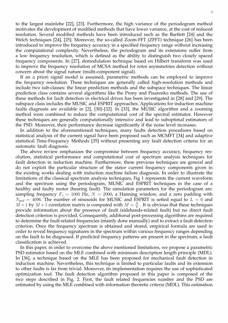
The above review emphasizes the compromise between frequency accuracy, frequency res-olution, statistical performance and computational cost of spectrum analysis techniques forfault detection in induction machine. Furthermore, these previous techniques are general anddo not exploit the particular structure of the stator current frequency components given inthe existing works dealing with induction machine failure diagnosis. In order to illustrate thelimitations of the classical spectrum analysis techniques, Fig 1 represents the current waveformand the spectrum using the periodogram, MUSIC and ESPRIT techniques in the case of ahealthy and faulty motor (bearing fault). The simulation parameters for the periodogram are:sampling frequency Fs = 1000 Hz, N = 2000, a Hanning window, and a zero padding withNpad = 4096. The number of sinusoids for MUSIC and ESPRIT is setted equal to L = 6 andM + 1 by M + 1 correlation matrix is computed with M = N
8. It is obvious that these techniques
provide information about the presence of fault (sidebands-related fault) but no direct faultdetection criterion is provided. Consequently, additional post-processing algorithms are requiredto determine the fault-related frequencies (mainly done manually) and to extract a fault detectioncriterion. Once the frequency spectrum is obtained and stored, empirical formula are used inorder to reveal frequency signatures in the spectrum within various frequency ranges dependingon the fault to be diagnosed. If predicted frequency patterns are present in the spectrum, a faultclassification is achieved.
In this paper, in order to overcome the above mentioned limitations, we propose a parametricPSD estimator based on the MLE combined with minimum description length principle (MDL).In [36], a technique based on the MLE has been proposed for mechanical fault detection ininduction machine. Nevertheless, this technique is limited to particular faults and its extensionto other faults is far from trivial. Moreover, its implementation requires the use of sophisticatedoptimization tool. The fault detection algorithm proposed in this paper is composed of thetwo steps described in Fig. 2. First, the fault related frequencies number and the PSD areestimated by using the MLE combined with information theoretic criteria (MDL). This estimation
4
0 2 4 6 8 10 12 14 16 18−2.5
−2
−1.5
−1
−0.5
0
0.5
1
1.5
2
2.5
sig
na
l (A
)
time(sec)
bearing failure
(a) Stator current waveform(Faulty case).
0 10 20 30 40 50 60 70 80 90 100−100
−80
−60
−40
−20
0
20
PS
D [
dB
]
Frequency[Hz]
healthy machinebearing failure
(b) Periodogram-basedspectrum (Hanning window).
0 20 40 60 80 100−40
−20
0
20
40
60
80
100
120
140
PS
D [d
B]
Frequency[Hz]
healthy machinebearing failure
(c) MUSIC-based pseudospec-trum.
0 20 40 60 80 100−80
−70
−60
−50
−40
−30
−20
−10
0
10
PS
D [d
B]
Frequency[Hz]
healthy machinebearing failure
(d) ESPRIT-based spectrum.
Fig. 1 . Classical spectrum analysis techniques on experimental data.
1
Statorcurrent
acquisition- PSD using
MLE + MDL
v- Criterion
computation-C Decision
algorithm-
Inductionmachine
state
Proposed approach
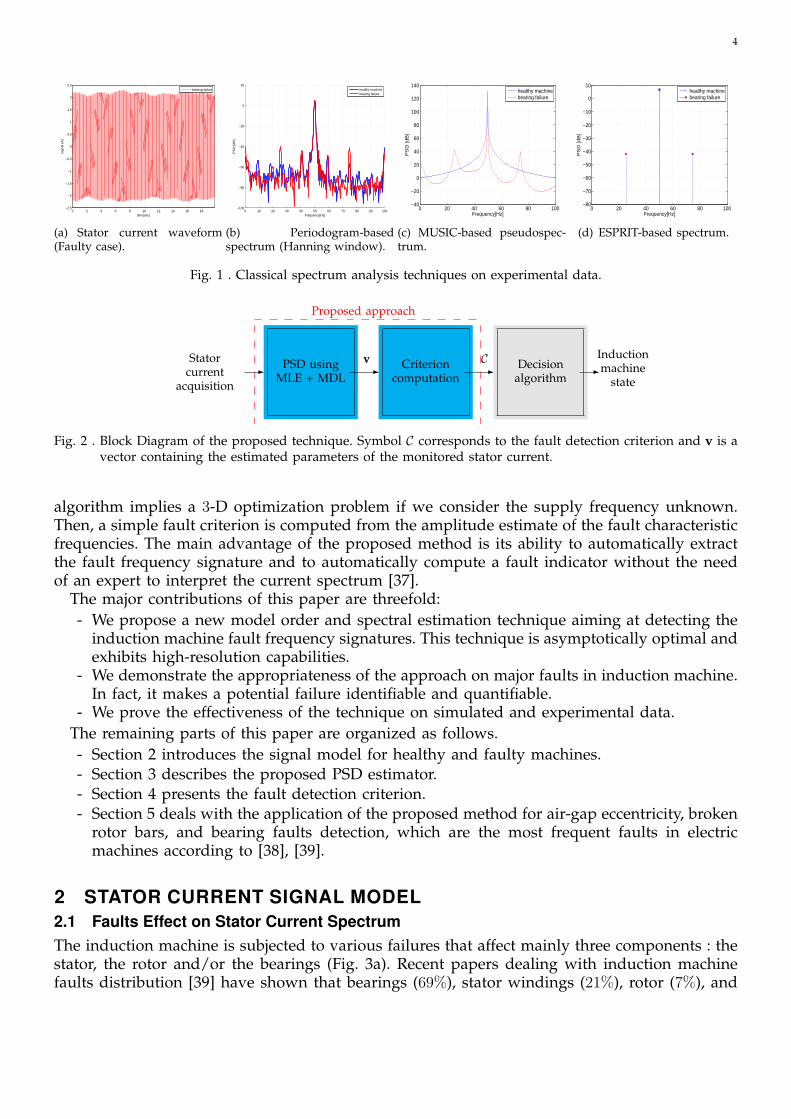
Fig. 2 . Block Diagram of the proposed technique. Symbol C corresponds to the fault detection criterion and v is avector containing the estimated parameters of the monitored stator current.
algorithm implies a 3-D optimization problem if we consider the supply frequency unknown.Then, a simple fault criterion is computed from the amplitude estimate of the fault characteristicfrequencies. The main advantage of the proposed method is its ability to automatically extractthe fault frequency signature and to automatically compute a fault indicator without the needof an expert to interpret the current spectrum [37].
The major contributions of this paper are threefold:- We propose a new model order and spectral estimation technique aiming at detecting the
induction machine fault frequency signatures. This technique is asymptotically optimal andexhibits high-resolution capabilities.
- We demonstrate the appropriateness of the approach on major faults in induction machine.In fact, it makes a potential failure identifiable and quantifiable.
- We prove the effectiveness of the technique on simulated and experimental data.The remaining parts of this paper are organized as follows.- Section 2 introduces the signal model for healthy and faulty machines.- Section 3 describes the proposed PSD estimator.- Section 4 presents the fault detection criterion.- Section 5 deals with the application of the proposed method for air-gap eccentricity, broken
rotor bars, and bearing faults detection, which are the most frequent faults in electricmachines according to [38], [39].
2 STATOR CURRENT SIGNAL MODEL2.1 Faults Effect on Stator Current SpectrumThe induction machine is subjected to various failures that affect mainly three components : thestator, the rotor and/or the bearings (Fig. 3a). Recent papers dealing with induction machinefaults distribution [39] have shown that bearings (69%), stator windings (21%), rotor (7%), and

5 2
Bearing
51%
Rotor bar5%
Shaft/coupling2%
External
(environment voltage,
and load will likely
Occur again)
16%
Unknown
(no root cause failure
analysis performed)
10% Stator winding
(may have been voltage,
water, overload, etc.)
16%
(a) Breakdown of failed components by distribution.
Bearing
69%
Stator winding
(may have been voltage,
water, overload, etc.)
21% Rotor bar7%
Shaft/coupling3%
(b) Extrapolated distribution of failure by motor components.(a) Breakdown of failed components by distribution.
2
Bearing
51%
Rotor bar5%
Shaft/coupling2%
External
(environment voltage,
and load will likely
Occur again)
16%
Unknown
(no root cause failure
analysis performed)
10% Stator winding
(may have been voltage,
water, overload, etc.)
16%
(a) Breakdown of failed components by distribution.
Bearing
69%
Stator winding
(may have been voltage,
water, overload, etc.)
21% Rotor bar7%
Shaft/coupling3%
(b) Extrapolated distribution of failure by motor components.(b) Extrapolated distribution of failure by motor components.
Fig. 3 . Distribution of known motor failures for the petroleum and chemical industries [39].
Table 1 . Induction machine faults signatures [11], [12].
Induction
machine state
Frequency
SignatureParameters Ω
Bearing
Damage|fs ± kfo| k = 1, 2, 3, ... Ω = fs, f0
Broken
Rotor Barsfs[k( 1−s
p)± s
]kp
= 1, 3, 5, 7, 11, 13... Ω = fs, s
Air Gap
Eccentricityfs[1± k
(1−sp
)]k = 1, 2, 3, ... Ω = fs, s
Load
oscillationfs[1± k
(1−sp
)]k = 1, 2, 3, ... Ω = fs, s
shaft/coupling (3%) are the most failing components (Fig. 3b). Most of the recent researches oninduction machine faults detection has been directed toward electrical monitoring with emphasison stator current supervision. In particular, the current spectrum is analysed to extract thefrequency components introduced by the fault. A summary of induction machine faults effectson stator current is presented in Table 1.
Where fs corresponds to the supply frequency, s is the per unit slip, and p is the pole-pairnumber. Symbol fo corresponds to one of the characteristic vibration frequencies introduced bybearing fault which depends on the bearing dimensions and mechanical rotor frequency [40]. In[41], it has been demonstrated that depending on the physical phenomena (eccentricity or torquevariations) introduced by bearing faults, the corresponding frequency signatures are different.Moreover, these signatures depends on the defected components. Concerning the load oscillation,the model presented holds only if the load oscillates at the rotating frequency [41], [42]. In fact,in the case of load oscillations, the stator current is modulated by the shaft rotational speed,

6
belt pass frequency, compression frequency, blades rotational frequency, meshing frequency,resonance frequency of the control loop, etc. Finally, concerning the eccentricity fault, we onlyfocus on the monitoring of the current at the fundamental sidebands of the supply frequencygiven in [11]. In fact, since space harmonics are usually of smaller amplitude, higher orderterms of these harmonics can be supposed to be less affected by the fault than the fundamentalfrequency. In general way, the fault detection methods monitors the behavior of the current atthe sidebands of the slot frequencies. These sidebands associated with eccentricity are given in[9].
The frequencies given by Table 1 are used in the faulty induction machine stator currentmodel described in the following section. When a fault occurs, the amplitude at these frequenciesincreases and reveal abnormal operating conditions.
2.2 Induction Machine Stator Current Signal ModelThe stator current signal model is based on the following assumptions:− H1: The received signal is modeled as a sum of 2L+ 1 sine waves embedded in noise. 2L
corresponds to the number of the sidebands around the supply frequency introduced bythe fault (whose amplitudes rise when a fault occurs).
− H2: The noise is white, Gaussian with zero-mean and variance σ2.− H3: The signal frequency content obeys to the particular structures given by Table 1.− H4: The matrix A(Ω) has full column rank 2×L+1, i.e. rank(A(Ω)) = 2L+1. This is verified
for N > 2L+ 1.In practice, H1 may not be verified since the induction machine stator current may contain
space- and time-harmonics. However, some of these harmonics can be eliminated by filteringthe stator current signal in order to focus on the fault-affected frequency bandwidth. Moreover,we must note that H1 requires the knowledge of L. In the present work, we propose a techniqueto estimate it from the stator current signal. Concerning the assumption H2, it is not particularlyrestrictive. In fact, if the noise process is not white and has unknown spectral shape, then accuratefrequency estimates can still be found if we estimate the sinusoids using the non-linear leastsquares (NLS) [15, Chapter 4, Introduction].
Under the assumption H1-H3, the stator-current samples x[n] can be expressed as
x[n] =L∑
k=−Lak cos
(2πfk(Ω)×
(n
Fs
)+ φk
)+ b[n] (2)
where b[n] corresponds to the noise sample. Symbols fk(Ω), ak and φk correspond to the fre-quency, the amplitude and the phase of the kth frequency component, respectively. Symbol Fscorresponds to the sampling rate. Note that the particular case where k = 0 corresponds to thefundamental frequency component.
The PSD is defined as the Discrete Time Fourier Transform of the covariance function ofx[n] [15]. Under the assumption H2 and that the initial phases φk, are independent randomvariables uniformly distributed on [−π π], the theoretical PSD of x[n] is given by Fig. 4 [15]. Inpractice, the PSD is unknown, and must be estimated from N samples. Using a matrix notation,x[n] (n = 0, · · · , N − 1) can be expressed as
x = A(Ω)v + b (3)
where:− x = [x[0], · · · , x[N − 1]]T is a N × 1 column vector containing the stator current samples,− b = [b[0], · · · , b[N − 1]]T is a N × 1 column vector containing the noise samples,

7 3
σ2PSD
ofx
[n]
ffs
a20
f−1(Ω)
a2−1
f−2(Ω)
a2−2
f1(Ω)
a21
f2(Ω)
a22
Amplitude of the frequency
components introduced
by a fault
Fig. 4 . Theoretical PSD for L = 2 [15].
− v is a 2(2L+1)×1 column vector containing the amplitudes and phases of the characteristicfault frequencies. This vector is given by
v = [a−L cos(φ−L) . . . aL cos(φL),−a−L sin(φ−L) . . .− aL sin(φL)]T (4)
A(Ω) is a N × 2(2L+ 1) matrix whose elements are given by
A(Ω) = [z−L . . . zL,y−L . . . yL] (5)
where
zk =
[1 cos
(2πfk(Ω)× 1
Fs
). . . cos
(2πfk(Ω)× N − 1
Fs
)]Tyk =
[0 sin
(2πfk(Ω)× 1
Fs
). . . sin
(2πfk(Ω)× N − 1
Fs
)]T(6)
Non-parametric estimators estimate the PSD from x without using any a priori knowledgeabout the signal. Departing from this approach, we propose a parametric estimator that exploitsthe signal model in (3) and the fault related frequency presented in Table 1. In this context,the computation of the current spectrum from stator current samples x is treated as a statisticalestimation problem. The main object is to estimate the parameters Ω in Table 1 and a relevantfault detection criterion.
3 PARAMETRIC PSD ESTIMATIONIn this section, we present the fault detection scheme based on the MLE. The MLE is an asymp-totically optimal estimator since it has the asymptotic properties of being unbiased, achieving theCramer-Rao lower bound, and having a Gaussian Probability Density Function [43]. Applicationfor PSD estimation has been investigated for harmonic and non-harmonic signal models in [44]and [45], respectively. Unfortunately, the MLE has a higher computational cost since it requiresthe optimization of a cost-function in high dimensional space. In the case of induction machinefault detection, we demonstrate that the MLE is computationally efficient since it leads to a2-D optimization problem that is easy to implement. Besides, an efficient implementation of the

8
MLE requires the knowledge of frequency components numbers which is called model orderestimation problem. In order to estimate the model order (fundamental frequency and 2 × Lsidebands produced by fault, where L has to be estimated), we propose to combine the MLEwith an order-dependent penalty term based on the MDL principle [46]. It must be emphasizedthat the sidebands number (2 × L) estimation is of great interest since it contribute to informus about the fault existence. Moreover, if the order is not estimated (chosen) correctly, the faultcharacteristic frequency may erroneously be estimated at, for example, half or double of the truevalue. In addition to the exact MLE, we propose an FFT-based approximate approach that leadsto significant computational complexity reduction.
3.1 Proposed EstimatorThe MLE is used in order to estimate v and Ω. Then a penalty term is applied to the MLE costfunction in order to estimate the model order i.e. L.
3.1.1 Estimate of v and Ω
The ML estimator of v, and Ω is given by
v, Ω = arg maxv,Ω
log(p(x; v,Ω)) (7)
where p(x; v,Ω) is the probability density function (pdf) of x which is given by
p(x; v,Ω) =1
(2πσ2)N2
× exp
[− 1
2σ2(x−A(Ω)v)T (x−A(Ω)v)
](8)
where (.)T denotes the matrix transpose, and a noise is considered white Gaussian noise withzero mean and variance equal to σ2 i.e. b[n] ∼ N (0, σ2). The ML estimates of Ω and v areobtained by maximizing the pdf with respect to the unknown parameters. The maximization in(7) is equivalent to the minimization of the following cost function:
L(x; v,Ω) = (x−A(Ω)v)T (x−A(Ω)v) (9)
Differentiating L(x; v,Ω) with respect to v and setting the derivative equal to 0 leads to theML estimate of v denoted v (see Appendix A for the proof).
v = A†(Ω)x (10)
where A†(Ω) is the pseudo-inverse of A(Ω) i.e.
A†(Ω) =(AT (Ω)A(Ω)
)−1 AT (Ω) (11)
and where (.)−1 corresponds to the matrix inverse.The ML estimate of Ω is obtained by minimizing L(x; v,Ω) with respect to Ω. By replacing v
by v in (9), we obtain (see Appendix B):
Ω = arg maxΩJ (Ω) (12)
where:J (Ω) = xTA(Ω)A†(Ω)x (13)
9
3.1.2 Estimate of model order LThe estimation of L enhances the performance of the ML estimates of Ω. The informationtheoretic criteria are used to estimate L [47]. In fact, a penalty term based on MDL principleis applied to the MLE cost function in order to estimate L. Hence, the estimation of L can beperformed by maximizing the penalized ML estimate of Ω [46] as follows
Ω, L = arg minΩ,L
(−2 log p(x, v, σ2,Ω, L) + c(g,N)) (14)
where:− The noise variance estimate is given by
σ2 =1
N‖x−A(Ω)v‖ (15)
− The penalty function c(g,N) depends on the number of free parameters g and the numberof data samples N . Under the assumption that the number of the components is equal to2L + 1, g = 4L + 4. The criterion information rule used within this paper is the minimumdescription length (also called the Bayesian Information Criterion Rule) [46] and is givenby
c(g,N) = g log(N) (16)
A straightforward computation leads to the following optimization problem (see Appendix Cfor the proof):
Ω, L = arg maxΩ,L−(xTx− J (Ω)
)× exp
(c(g,N)
N
)(17)
Finally, the PSD estimate of the stator current is composed of two steps: a) the estimates ofΩ, and L are obtained from (17), and b) the vector v containing the amplitude and the phaseof the fault characteristic frequencies is estimated by replacing Ω, and L with its estimates in(10). Because of its statistical properties, one should note that the Maximum Likelihood estimateremains the most accurate method for PSD estimation even in those cases where the noise iscolored [15]. In particular, this estimator overcomes the frequency resolution limitation of theperiodogram. Furthermore, as opposed to other techniques, the proposed approach exploits thefaults characteristic frequencies to improve the accuracy of the PSD estimate.
About the implementation, the main difficulty relies on the optimization problem in (17). Asthe maximum can not be found analytically, numerical method should be used to estimate Ωand L. In our context, the cost function is only composed of three parameters, which implies amaximization in a 3-D space. The search space is relatively limited since the variation range ofΩ and L are approximately known. For these reasons, we propose to perform the maximizationof (17) with a grid-search algorithm. This algorithm evaluates the cost function at the verticesof a rectangular grid, and chooses the vertex with the highest value. It should be noted that themaximization step could be computationally demanding since it requires the construction andthe inversion of a large matrix for each vertex of the grid.
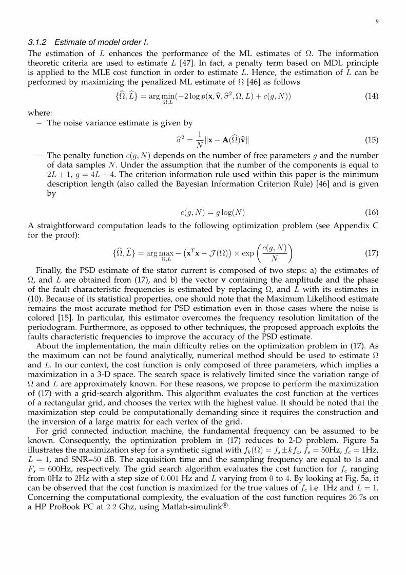
For grid connected induction machine, the fundamental frequency can be assumed to beknown. Consequently, the optimization problem in (17) reduces to 2-D problem. Figure 5aillustrates the maximization step for a synthetic signal with fk(Ω) = fs±kfc, fs = 50Hz, fc = 1Hz,L = 1, and SNR=50 dB. The acquisition time and the sampling frequency are equal to 1s andFs = 600Hz, respectively. The grid search algorithm evaluates the cost function for fc rangingfrom 0Hz to 2Hz with a step size of 0.001 Hz and L varying from 0 to 4. By looking at Fig. 5a, itcan be observed that the cost function is maximized for the true values of fc i.e. 1Hz and L = 1.Concerning the computational complexity, the evaluation of the cost function requires 26.7s ona HP ProBook PC at 2.2 Ghz, using Matlab-simulink R©.

10
0 0.2 0.4 0.6 0.8 1 1.2 1.4 1.6 1.8 2−80
−60
−40
−20
0
20
40
Fault related frequency
Cos
t fun
ctio
n (d
B)
L=0L=1L=2L=3L=4
(a) J (fc) (N = 500).
0 0.2 0.4 0.6 0.8 1 1.2 1.4 1.6 1.8 219.9
19.92
19.94
19.96
19.98
20
20.02
20.04
20.06
20.08
20.1
Fault related frequency
Cos
t fun
ctio
n (d
B)
L=0L=1L=2L=3L=4
(b) J (fc) (Zoom).
0 0.2 0.4 0.6 0.8 1 1.2 1.4 1.6 1.8 2−100
−90
−80
−70
−60
−50
−40
−30
−20
−10
Fault related frequency
App
rox.
cos
t fun
ctio
n (d
B)
L=0L=1L=2L=3L=4
(c) Ja(fc) ( N = 2000).
0 0.2 0.4 0.6 0.8 1 1.2 1.4 1.6 1.8 2
−12.65
−12.6
−12.55
−12.5
−12.45
−12.4
Fault related frequency
App
rox.
cos
t fun
ctio
n (d
B)
L=0L=1L=2L=3L=4
(d) Ja(fc) (zoom).
Fig. 5 . Exact and approximate cost function (fs = 50Hz, fc = 1Hz, Lopt = 1, Fs = 1kHz and SNR = 50dB).
3.2 Link with FFTThe computational complexity of the PSD estimator can be reduced when the number of samples,N , goes to infinity. Indeed, by using the following limit (see, e.g., [43, Example 7.16]).
limN→∞
2
N
(AT (Ω)A(Ω)
)= IN (18)
where IN corresponds to the N ×N identity matrix. The cost function can be approximated as(see Appendix D)
Ja(Ω) = limN→∞
J (Ω) =2
NxTA(Ω)AT (Ω)x = 2
L∑k=−L
∣∣∣∣∣ 1√N
N−1∑n=0
x[n]e−2jπ(fk(Ω)) nFs
∣∣∣∣∣2
(19)
where the last equality comes from the fact that x[n] ∈ R. The last equation can be expressedaccording to the Discrete Fourier Transform (DFT) of x[n]. Indeed,
Ja(Ω) = 2L∑
k=−L|DFTx [fk(Ω)/Fs]|2 (20)
where DFTx[f ] is the DFT computed at frequency f i.e.
DFTx[f ] =1√N
N−1∑n=0
x[n]e−2jπfn (21)
Finally the approximate ML estimate of Ω is simply obtained by replacing J (Ω) with Ja(Ω) in(12). It must be stressed that an approximate MLE can be obtained if fk(Ω)/Fs is not close to 0and 1/2.
Similarly, the approximate ML estimator of the vector v is then computed using (22).
v =2
NAT (Ω)x (22)
This approximate approach can be extended in order to estimate the model order L as follows
Ω, L = arg maxΩ,L−(xTx− Ja(Ω)
)× exp
(c(g,N)
N
)(23)
Equations (23) and (20) show that the approximate cost function is reduced to a sum of DFTbins. This makes the approximate approach attractive for the following reasons: a) Most DSP-boards include functions for DFT computation b) the DFT can be efficiently computed usingthe FFT. However, it should be stressed that the accuracy of the approximation highly depends
11
on the signal length N . In particular, the approximation in (18) is no longer valid for shortsignals. In this case, the DFT of the stator current signal exhibits sidelobes which affect thefrequency resolution. The sidelobes can mask components close in frequency and then lead tofalse conclusions. Moreover, the sidelobes could be interpreted as fault characteristic frequencyand then lead to false alarm. This may be overcame by choosing different windows (Hanning,Blackman) in order to attenuate sidelobes [23]. Moreover, interpolating the DFT by zero paddingthe data can often increase the frequency accuracy and thus improve the amplitude estimate [15].The approximated method is then limited by the FFT algorithm resolution: the parameters areestimated correctly as long as the observed signal length N
Fsis large enough compared to the
inverse of the smallest frequency difference between two neighbouring poles of the signal i.e.(24).
N 1
mink1 6=k2 |fk2 − fk1 |(24)
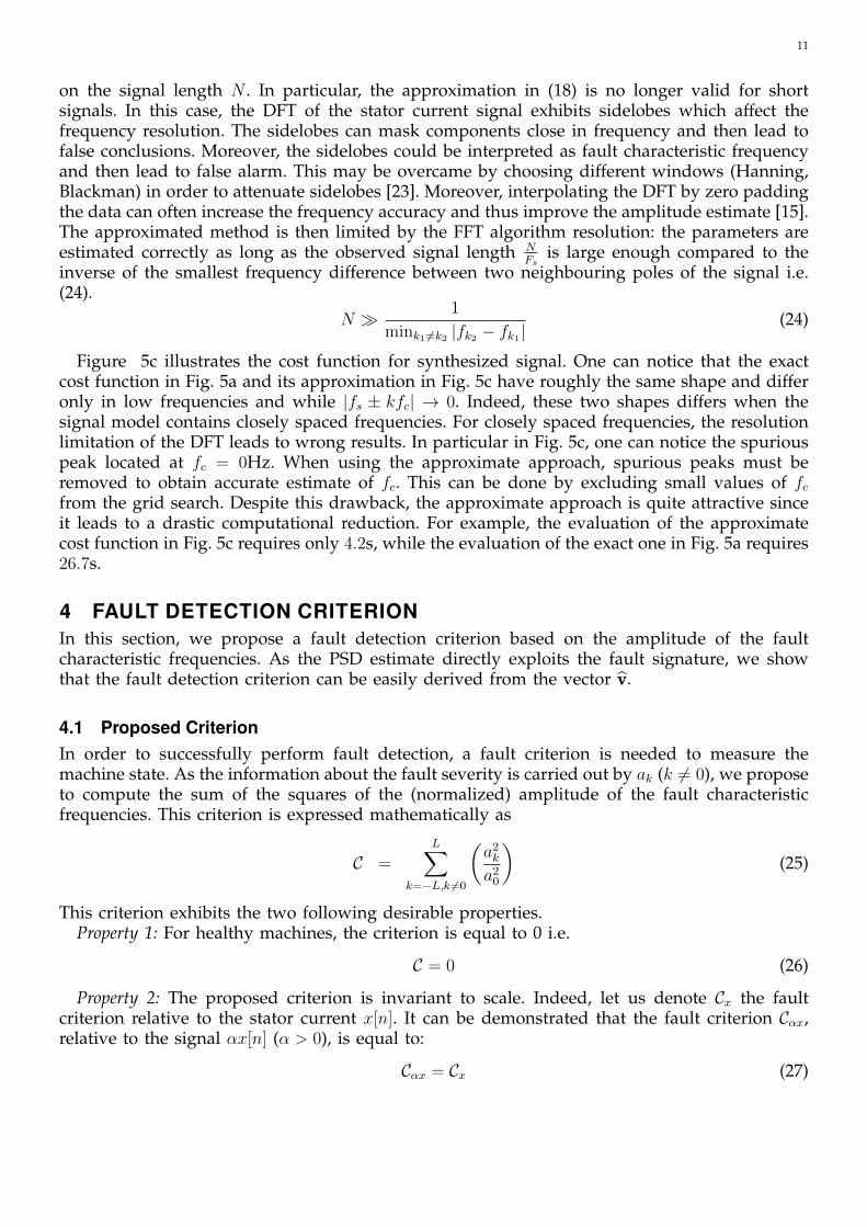
Figure 5c illustrates the cost function for synthesized signal. One can notice that the exactcost function in Fig. 5a and its approximation in Fig. 5c have roughly the same shape and differonly in low frequencies and while |fs ± kfc| → 0. Indeed, these two shapes differs when thesignal model contains closely spaced frequencies. For closely spaced frequencies, the resolutionlimitation of the DFT leads to wrong results. In particular in Fig. 5c, one can notice the spuriouspeak located at fc = 0Hz. When using the approximate approach, spurious peaks must beremoved to obtain accurate estimate of fc. This can be done by excluding small values of fcfrom the grid search. Despite this drawback, the approximate approach is quite attractive sinceit leads to a drastic computational reduction. For example, the evaluation of the approximatecost function in Fig. 5c requires only 4.2s, while the evaluation of the exact one in Fig. 5a requires26.7s.
4 FAULT DETECTION CRITERIONIn this section, we propose a fault detection criterion based on the amplitude of the faultcharacteristic frequencies. As the PSD estimate directly exploits the fault signature, we showthat the fault detection criterion can be easily derived from the vector v.
4.1 Proposed CriterionIn order to successfully perform fault detection, a fault criterion is needed to measure themachine state. As the information about the fault severity is carried out by ak (k 6= 0), we proposeto compute the sum of the squares of the (normalized) amplitude of the fault characteristicfrequencies. This criterion is expressed mathematically as
C =L∑
k=−L,k 6=0
(a2k
a20
)(25)
This criterion exhibits the two following desirable properties.Property 1: For healthy machines, the criterion is equal to 0 i.e.
C = 0 (26)
Property 2: The proposed criterion is invariant to scale. Indeed, let us denote Cx the faultcriterion relative to the stator current x[n]. It can be demonstrated that the fault criterion Cαx,relative to the signal αx[n] (α > 0), is equal to:
Cαx = Cx (27)
124
Stator currentsamples x[n]
Fault frequencymodel fk(Ω)
Find Ω, and L
Estimate v
L = 0L 6= 0
Compute C
Fault severity/Decision No fault
PSD
Esti
mat
e
Fig. 6 . Fault detection algorithm.
Rb
L b
L eRe
iRq-2
iRq-1
iRq
iR1
iR2
iR3
ie
L e
L e
L e
L e
L e
L e
L e
L e
L e
L e
L e
Re
Re
Re
ReRe
Re
Re
Re
Re
Re
Re
Rb
Rb
Rb
Rb
Rb
Rb
L b
L b
L b
L b
L bL b
Fig. 7 . Rotor bars equivalent circuit [14].
The proposed criterion in (25) depends on the amplitudes ak (k = −L, · · · , L). Once the PSDis estimated, ak can be extracted from the vector v. However, using the structure of v in (4), itcan be shown that C can be obtained directly from v without computing ak. Indeed, the faultcriterion in (25) can be expressed under the following matrix form (see the appendix E for proof):
C =vTv
vTMv− 1 (28)
where M is a (4L+ 2)× (4L+ 2) matrix which is given by[EL+1,L+1 0
0 EL+1,L+1
](29)
and where Eu,v is the (2L + 1) × (2L + 1) elementary matrix which is 1 in the uth row and vth
column and is zero elsewhere. In practice, one should note that v is unknown and must bereplaced by its estimate v in (28) to compute C.
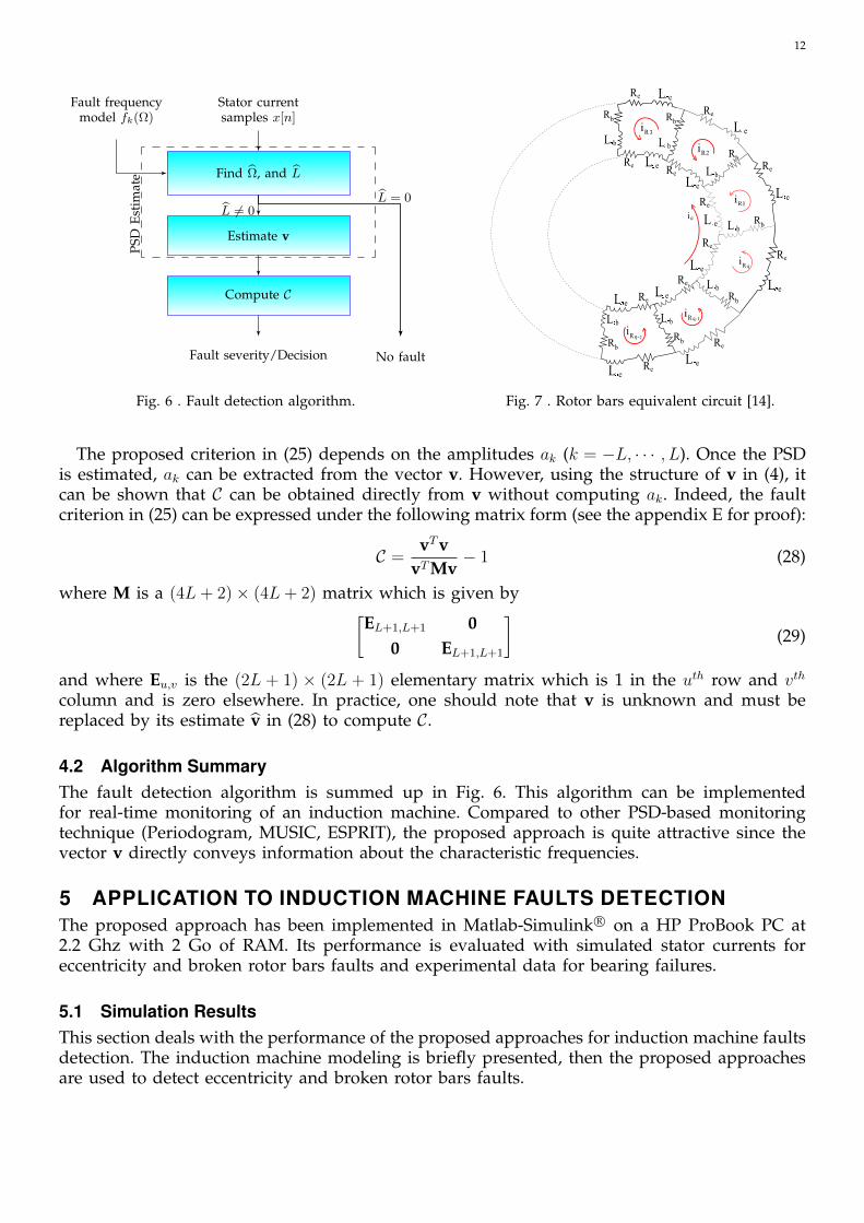
4.2 Algorithm SummaryThe fault detection algorithm is summed up in Fig. 6. This algorithm can be implementedfor real-time monitoring of an induction machine. Compared to other PSD-based monitoringtechnique (Periodogram, MUSIC, ESPRIT), the proposed approach is quite attractive since thevector v directly conveys information about the characteristic frequencies.
5 APPLICATION TO INDUCTION MACHINE FAULTS DETECTIONThe proposed approach has been implemented in Matlab-Simulink R© on a HP ProBook PC at2.2 Ghz with 2 Go of RAM. Its performance is evaluated with simulated stator currents foreccentricity and broken rotor bars faults and experimental data for bearing failures.
5.1 Simulation ResultsThis section deals with the performance of the proposed approaches for induction machine faultsdetection. The induction machine modeling is briefly presented, then the proposed approachesare used to detect eccentricity and broken rotor bars faults.
13
5.1.1 Induction machine modelingAn induction machine model for healthy and faulty machines has been developed based onthe coupled magnetic circuits theory [13], [48], [49]. This method is based on the followingassumptions:− Negligible saturation;− Negligible eddy current, friction and windage losses;− Insulated rotor bars.The induction machine stator consists of three phase concentric winding. Each winding is
considered as a separated coil. The cage rotor has n bars which can be described as n identicaland equally spaced rotor loops; each loop is formed by two adjacent rotor bars connected bythe end-ring portions.
The rotor cage equivalent circuit showing the rotor loops and different currents is displayedin Fig. 7.
The stator currents are obtained by solving the system of differential equations in (30).ddt
I = −L−1(
R + Ω ddθm
L)
I + L−1Vddt
Ω = 12J
IT(
ddθm
L)
I− fJ
Ω− 1J
ΓCddtθm = Ω
(30)
where :
V =
[Vs
0
]I =
[IsIr
]R =
[Rs 00 Rr
]L =
[Lss LsrLrs Lrr
]Symbols Vs, Is and Ir correspond to the stator voltage vector, the stator current vector and therotor current vector, respectively. Inductances Lss, Lrr, Lrs and Lsr correspond to the self andmutual inductances between stator windings and rotor windings. Resistances Rs and Rr referto the stator and cage resistances and ΓC , Ω and θm correspond to the load torque, the rotormechanical speed and the rotor angular position, respectively. Finally, J is the rotating massesinertia and f is the viscous friction coefficient.
In (30), the machine inductances L are carried out using the air-gap magnetic energy, whichis determined by means of the actual geometry and winding layout of the machine. A Matlab-simulink R©-based tool for faulty induction machines has been developed to generate faults databaseand therefore to allow testing the proposed faults detection approach.
In these simulations dynamic eccentricities are introduced to emulate a bearing fault. It hasbeen demonstrated that single-point bearings faults have an effect over the machine eccentricityand/or load variations [40]–[42], [50]. In fact, bearing fault will induce mechanical eccentricities,but also load-torque variations. Hence, in the carried-out simulations, bearing faults are emulatedby generating only one sort of physical phenomena: rotating eccentricities at bearing character-istic fault frequency fc. These eccentricities leads to periodical changes in the induction machineinductances [40]. Moreover, broken rotor bars are emulated by suppressing the correspondingbroken rotor bar.
Therefore, a 4 kW induction machine operating under nominal load condition have beensimulated. Three machines have been considered: a healthy machine, a faulty one affected bya 10% (static, dynamic and mixed) eccentricity, and a faulty one affected by broken rotor bars.Simulations were performed with a supply frequency equal to fs = 50 Hz and nominal speedequal to Ωm = 1425rpm. The stator current signals have been recorded during 1 second with a1 kHz sampling rate.
14
0 50 100 150−120
−100
−80
−60
−40
−20
0
20
40
Frequency (Hz)
Perio
dogr
am
Healthy machineEccentricity fault
(a) Periodogram (Hanning Window).
0 50 100 150−20
0
20
40
60
80
100
Frequency (Hz)
PSD
estim
ate
Healthy machineEccentricity fault
(b) MUSIC pseudospectrum. (L=16).
0 50 100 150−80
−60
−40
−20
0
20
40
Frequency (Hz)
PSD
estim
ate
Healthy machineEccentricity fault
(c) Proposed Approach.
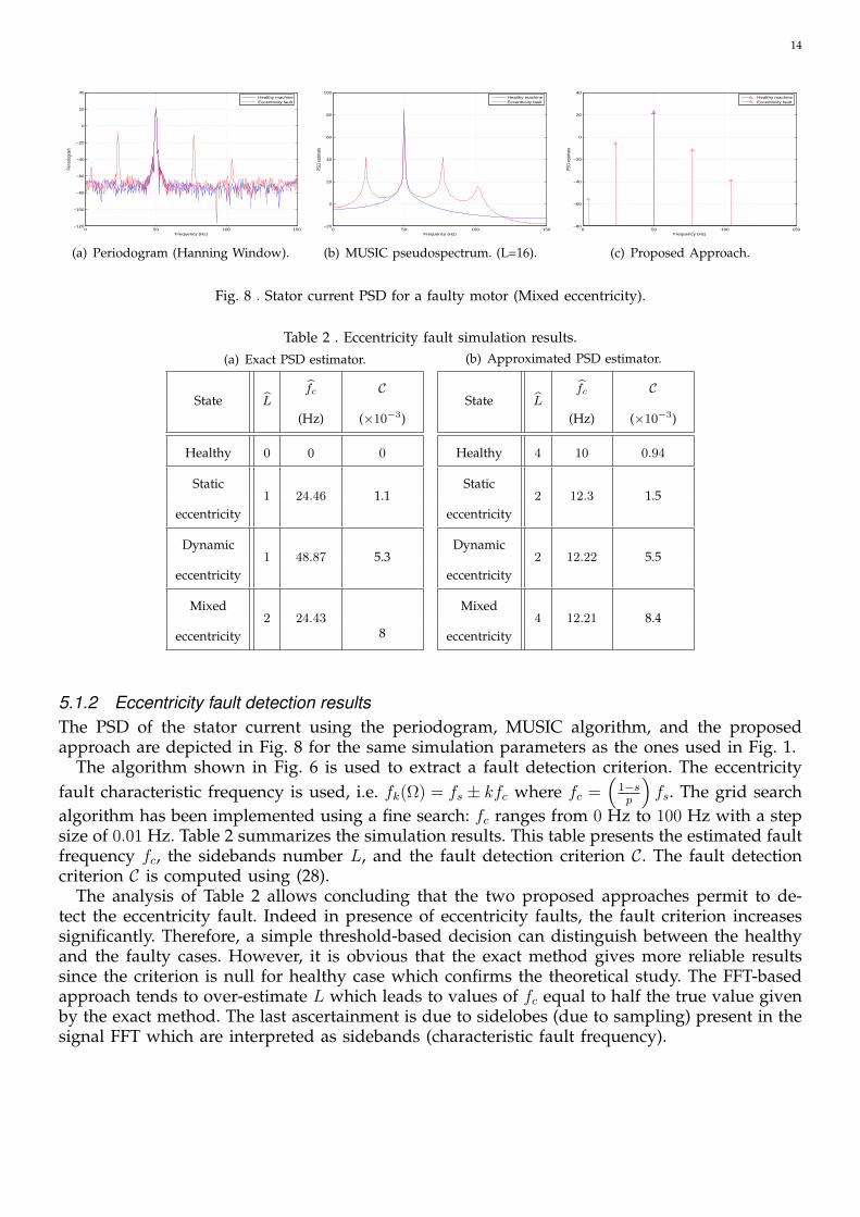
Fig. 8 . Stator current PSD for a faulty motor (Mixed eccentricity).
Table 2 . Eccentricity fault simulation results.(a) Exact PSD estimator.
State Lfc
(Hz)
C
(×10−3)
Healthy 0 0 0
Static1 24.46 1.1
eccentricity
Dynamic1 48.87 5.3
eccentricity
Mixed2 24.43
8eccentricity
(b) Approximated PSD estimator.
State Lfc
(Hz)
C
(×10−3)
Healthy 4 10 0.94
Static2 12.3 1.5
eccentricity
Dynamic2 12.22 5.5
eccentricity
Mixed4 12.21 8.4
eccentricity
5.1.2 Eccentricity fault detection resultsThe PSD of the stator current using the periodogram, MUSIC algorithm, and the proposedapproach are depicted in Fig. 8 for the same simulation parameters as the ones used in Fig. 1.
The algorithm shown in Fig. 6 is used to extract a fault detection criterion. The eccentricityfault characteristic frequency is used, i.e. fk(Ω) = fs ± kfc where fc =
(1−sp
)fs. The grid search
algorithm has been implemented using a fine search: fc ranges from 0 Hz to 100 Hz with a stepsize of 0.01 Hz. Table 2 summarizes the simulation results. This table presents the estimated faultfrequency fc, the sidebands number L, and the fault detection criterion C. The fault detectioncriterion C is computed using (28).
The analysis of Table 2 allows concluding that the two proposed approaches permit to de-tect the eccentricity fault. Indeed in presence of eccentricity faults, the fault criterion increasessignificantly. Therefore, a simple threshold-based decision can distinguish between the healthyand the faulty cases. However, it is obvious that the exact method gives more reliable resultssince the criterion is null for healthy case which confirms the theoretical study. The FFT-basedapproach tends to over-estimate L which leads to values of fc equal to half the true value givenby the exact method. The last ascertainment is due to sidelobes (due to sampling) present in thesignal FFT which are interpreted as sidebands (characteristic fault frequency).

15
0 50 100 150 200 250 300 350−160
−140
−120
−100
−80
−60
−40
−20
0
20
40
PSD
[dB]
Frequency[Hz]
Healthy machineBroken rotor bars
(a) Periodogram (Hanning window).
0 50 100 150 200 250 300 350−50
0
50
100
150
200
Frequency (Hz)
PSD
estim
ate
Healthy machineBroken rotor bars
(b) MUSIC pseudospectrum. (L=16).
0 50 100 150 200 250 300 350−80
−70
−60
−50
−40
−30
−20
−10
0
10
20
30
Frequency (Hz)
PSD
estim
ate
Healthy machineBroken rotor bars
(c) Proposed Approach.
Fig. 9 . PSD of the stator current with 3 broken rotor bars.
5.1.3 Broken rotor bars fault detection resultsBroken rotor bar is one of the electrical faults that is difficult to detect since the squirrel cagecurrent can not be acquired. The PSD of the stator current using the periodogram, MUSICalgorithm, and the proposed approach are depicted in Fig. 9 for the same simulation parametersas the ones used in Fig. 1.
The broken rotor bars characteristic frequency is used in the signal model i.e. fk(Ω) = fk(fs, s) =
fs
[k(
1−sp
)± s]. Computer simulations have been performed for assessment of operating fea-
tures of the proposed fault detection scheme.
Table 3 . Broken rotor bars simulation results.(a) Exact PSD estimator.
State L k/ps
(%)
C
(×10−3)
Healthy 0 0 0 0
1 broken bar 3 1, 3, 5 5.8 4.6
2 broken bars 4 1, 3, 5, 7 6.2 24.4
3 broken bars 5 1, 3, 5, 7, 11 6.6 49.7
(b) Approximated PSD estimator.
State L k/ps
(%)
C
(×10−3)
Healthy 1 1 3.13 1.8
1 broken bar 3 1, 3, 5 5.85 4.3
2 broken bars 4 1, 3, 5, 7 6.16 22.6
3 broken bars 5 1, 3, 5, 7, 11 6.57 45.2
Table 3 gives simulation results for 1 to 3 broken rotor bars for both the exact and FFT-basedtechniques. The broken bars are adjacent. The criterion has been evaluated for different faultdegrees. It can be noticed that the fault criterion varies in proportion to the number of brokenrotor bars. The same conclusions can be drawn from the broken rotor bars results. It is worthyto notice that in the exact approach case, the estimation of k
pleads to informations about faults
presence. This is not the case for FFT-based approach since the algorithm interprets sidelobesas sidebands which may lead to false alarm.
5.2 Experimental ResultsThis section reports on the performance of the proposed approaches. First, the test rig is pre-sented, then the proposed techniques was applied off-line using Matlab for bearing faults de-tection in a conventional induction machine.
16
Bearing fault Fault related frequency Theoretical values (Hz)
Cage defect fc = fr2
(1− d
Dcos(α)
)[14.4, 27.077]
Ball defect fbd = Ddfr(
1− d2
D2 cos2(α))
[105.5, 119.47]
Inner raceway fid = nfr2
(1 + d
Dcos(α)
)[154.04, 255.1]
Outer raceway fod = nfr2
(1− d
Dcos(α)
)[115.5, 216.6]
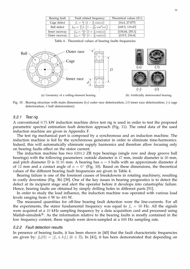
Table 4 . Theoretical values of bearing faults frequencies5
•
Outer race
Cage
Inner race
Ball
D
d
α
(c) Geometry of a rolling-element bearing.
(α) (β)
(γ) (δ)
(d) Artificially deteriorated bearing.(a) Geometry of a rolling-element bearing.
5
•
Outer race
Cage
Inner race
Ball
D
d
α
(c) Geometry of a rolling-element bearing.
(α) (β)
(γ) (δ)
(d) Artificially deteriorated bearing.(b) Artificially deteriorated bearing.
Fig. 10 . Bearing structure with main dimensions ((α) outer race deterioration, (β) inner race deterioration, (γ) cagedeterioration, δ ball deterioration).
5.2.1 Test rigA conventional 0.75 kW induction machine drive test rig is used in order to test the proposedparametric spectral estimation fault detection approach (Fig. 11). The rated data of the usedinduction machine are given in Appendix F.
The test rig mechanical part is composed by a synchronous and an induction machine. Theinduction machine is fed by the synchronous generator in order to eliminate time-harmonics.Indeed, this will automatically eliminate supply harmonics and therefore allow focusing onlyon bearing faults effect on the stator current.
The induction machine has two 6204.2 ZR type bearings (single row and deep groove ballbearings) with the following parameters: outside diameter is 47 mm, inside diameter is 20 mm,and pitch diameter D is 31.85 mm. A bearing has n = 8 balls with an approximate diameter dof 12 mm and a contact angle of α = 0 (Fig. 10). Based on these dimensions, the theoreticalvalues of the different bearing fault frequencies are given in Table 4.
Bearing failure is one of the foremost causes of breakdowns in rotating machinery, resultingin costly downtime (Fig. 3b) [39]. One of the key issues in bearing prognostics is to detect thedefect at its incipient stage and alert the operator before it develops into catastrophic failure.Hence, bearing faults are obtained by simply drilling holes in different parts [51].
In order to study the load influence, the induction machine was operated with various loadlevels ranging from 0 W to 400 W.
The measured quantities for off-line bearing fault detection were the line-currents. For allthe experiments, the stator fundamental frequency was equal to fs = 50 Hz. All the signalswere acquired at a 10 kHz sampling frequency by a data acquisition card and processed usingMatlab-simulink R©. As the information relative to the bearing faults is mostly contained in thelow frequency content, these signals were down-sampled at a 600 Hz sampling rate.
5.2.2 Fault detection resultsIn presence of bearing faults, it has been shown in [40] that the fault characteristic frequenciesare given by: fk(Ω) = |fs ± kfc| (k ∈ Z). In [41], it has been demonstrated that depending on

17
6
Synchro.generator
DCmotor
DCgenerator
Induction machine
Load Tacho generator
Data acqui.card 10 kHz
Fault detection algorithm
RST
Fig. 11 . Test rig scheme.
the bearing fault effect on the induction machine behavior (eccentricity or torque variations)the bearing fault-related frequencies in the stator current spectrum is different. In this section,we consider only the case where the localized single-point bearing defects leads to the torquevariations. Hence, the model in [40] has been considered.
The algorithm in Fig. 6 is again used to extract a fault detection criterion. Similarly to thesimulation configuration, the number L has been estimated in order to decide whether theinduction machine is operating with healthy bearings or damaged once. If L = 0 then thebearings are safe, otherwise the bearing is damaged and criterion in (28) is computed in orderto measure the fault severity and then take decision. Preliminary tests have shown that mostof the characteristic fault frequencies are greater than fs = 50 Hz which means that most ofthe frequency components related to fault are located at the right-side of the supply frequencyfs due to the absolute value of the frequencies introduced by faults (Table 1). Therefore, theproposed approach has been used to extract these right-side components. This simplification isnot equivalent to minimization of time-harmonics in power supply since these frequencies aredifferent from multiples of the fundamental frequency fs = 50 Hz.
Experimental results are reported in Figs. 12a and 12b for the exact and approximate ap-proaches, respectively. These figures display the criterion C for healthy and faulty machineswith various load levels.
For the exact algorithm, in the case of healthy machine, it is obvious that L = 0 which impliesthat the criterion is equal to 0. From this bar chart, it could be observed that the proposedcriterion significantly increases for each faulty machine, regardless of the fault type and loadlevel. Therefore, a simple estimation of L gives an indication of the existence of fault. However,In the case of approximated approach based on the FFT, the estimation of L can not be a reliableway to distinguish faulty from healthy case since L is different from 0 even if the machineis operating correctly. That’s why, the criterion computation is mandatory and threshold-based

18
1 2 3 40
0.01
0.02
0.03
0.04
0.05
0.06
Machine state
Crit
erio
n
No Load100W200w300W400W
(a) Exact PSD estimator: values of the fault detection criterionC for 1- Healthy case 2- Inner raceway fault 3- Cage fault 4-Ball fault.
1 2 3 40
0.01
0.02
0.03
0.04
0.05
0.06
0.07
0.08
0.09
0.1
Machine state
Crit
erio
n
No Load100W200w300W400W
(b) Approximate PSD estimator: values of the fault detectioncriterion C for 1- Healthy case 2- Inner raceway fault 3- Cagefault 4- Ball fault.
Fig. 12 . Performance of the proposed approaches on experimental data.
fault detector must be defined in order to distinguish between healthy and faulty machines.By comparing the two techniques, we can note that the exact approach is more reliable than
the approximated method which is less time consuming. However, it must be emphasized thatthe approximate approach has practical advantages since it is based on the DFT (easiness ofimplementation, fast computation with FFT). The two figures also show that the criterion Cdecreases with the load level; there is only one exception to this rule for the healthy machine inthe case of approximated algorithm. This could be explained by the fact that the load tends tohide the faults effect on the stator current [52]. This is clearly illustrated in Fig.12b when the loadis equal to 400 W. This results obviously confirms the effectiveness of the proposed techniqueover the FFT-based one.
The proposed technique allows detecting several induction machine faults. In order to charac-terize the fault (defected component, fault severity, etc.) another step is required which has notbeen addressed within this paper. However, the proposed technique may be used as an inputfor a fault classifier since it allows the extraction of the fault frequency signatures. Once thefault sensitive frequencies are extracted, the signatures given in the literature may be used todiscriminate several faults.
6 CONCLUSIONSThis paper has proposed a statistical-based approach for fault detection in induction machines.The proposed approach is composed of two steps: a) the estimation of the PSD with a newparametric technique, and b) the computation of a fault detection criterion.
The proposed PSD estimator has been computed using the maximum likelihood estimationapproach. As opposed to non-parametric PSD estimators, the proposed technique exploits thefault frequency signatures in order to improve the performance of the fault detection criterion.As a result, the proposed estimator has better frequency-resolution and frequency-accuracy thanother techniques such as the periodogram. When the number of samples goes to infinity, it hasalso been demonstrated that the proposed PSD estimator can be efficiently implemented usingthe Discrete Fourier Transform. However, this approximated method does not perform as wellas the exact method for short signals. Concerning the fault detection criterion, we have proposed
19
a criterion based on the amplitude of the fault-related frequencies. This criterion is theoreticallyequal to zero for healthy machine and increases for faulty once.
The proposed approach was successfully tested on simulations with eccentricity and brokenrotor bars faults and experimental test rig with various bearing faults and load conditions.Simulation and experimental results have corroborated the efficiency of the proposed method,regardless of the fault type in contrary to the FFT-based approach. Furthermore, these resultshave suggested that the estimation of L is very interesting since it allows to make a direct andfast first idea about the machine state.
Further investigations are required in order to study the effect of the induction machine faultsover the time- and space-harmonics of the stator current. Furthermore, the impact of theseharmonics over the reliability of the proposed technique should be highlighted.
APPENDIX AESTIMATION OF V
By expanding (9), we obtain:
L(x; v,Ω) = (x−A(Ω)v)T (x−A(Ω)v)
=(
xT − vTAT (Ω))(
x−A(Ω)v)
= xTx− 2vTAT (Ω)x + vTAT (Ω)A(Ω)v (31)
The derivative of L(x; v,Ω) with respect to v is equal to (see reference [53]):
∂L(x; v,Ω)
∂v= −2AT (Ω)x + 2AT (Ω)A(Ω)v
= −2AT (Ω) (x−A(Ω)v) (32)
Setting the above derivative to zero, we obtain the ML estimator of v, which is denoted v:
∂L(x; v,Ω)
∂v
∣∣∣∣∣v=v
= 0⇒ x = A(Ω)v (33)
Finally, we obtain the following ML estimator of v:
v = A†(Ω)x (34)
where A†(Ω) is the pseudo-inverse of A(Ω) i.e.
A†(Ω) =(AT (Ω)A(Ω)
)−1 AT (Ω) (35)
APPENDIX BESTIMATION OF ΩThe ML estimate of fk(Ω) is obtained by minimizing L(x; v,Ω) with respect to Ω. By replacingv by v in (9), we obtain:
L(x; v,Ω) = (x−A(Ω)v)T (x−A(Ω)v)
=(x−A(Ω)A†(Ω)x
)T (x−A(Ω)A†(Ω)x
)= xT
(IN −A(Ω)A†(Ω)
)x (36)

20
where the last equality has been obtained using (35). Neglecting the terms that do not dependon Ω, it can be shown that the ML estimate of Ω is given by
Ω = arg maxΩJ (Ω) (37)
where:
J (Ω) = xTA(Ω)A†(Ω)x (38)
APPENDIX CMODEL ORDER ESTIMATION
Departing from 14 we have
CF = −2 log p(x, v, σ2,Ω, L) + c(g,N) (39)
= 2 log(
(2πσ2)N2
)− 1
σ2
[(x−A(Ω)v)T (x−A(Ω)v)
]+ c(g,N) (40)
= N log((2πσ2)
)− 1
σ2
[(x−A(Ω)v)T (x−A(Ω)v)
]+ c(g,N) (41)
= log((2πσ2)
)− 1
σ2
[(x−A(Ω)v)T (x−A(Ω)v)
N
]+c(g,N)
N(42)
Using (15) the cost function is equivalent to
CF1 = log((2πσ2)
)+c(g,N)
N(43)
Since the exp function is strictly increasing, applying the exp on (43) gives
CF2 = (2πσ2)× exp
(c(g,N)
N
)(44)
Replacing (15) in (44) gives the equation given in (17).

21
APPENDIX DLINK WITH FFT PROOF
Ja(Ω) =2
NxTA(Ω)AT (Ω)x (45)
=2
N‖ATx‖F (46)
=2
N
∥∥∥[z−L . . . zL,y−L . . . yL]T [x[0] x[1] . . . x[N − 1]]T∥∥∥
F(47)
=2
N
∥∥∥∥∥∥∥∥∥∥∥∥∥∥∥∥
∑N−1n=0 x[n] cos(2πf−L(Ω)× n
Fs)
...∑N−1n=0 x[n] cos(2πfL(Ω)× n
Fs)∑N−1
n=0 x[n] sin(2πf−L(Ω)× nFs
)
...∑N−1n=0 x[n] sin(2πfL(Ω)× n
Fs)
∥∥∥∥∥∥∥∥∥∥∥∥∥∥∥∥F
(48)
=2
N
L∑k=−L
[N−1∑n=0
x[n]cos(2πfk(Ω)n
Fs)
]2
+
[N−1∑n=0
x[n]sin(2πfk(Ω)n
Fs)
]2
(49)
=2
N
L∑k=−L
∣∣∣∣∣N−1∑n=0
x[n]e−j2πfk(Ω) nFs
∣∣∣∣∣2
(50)
APPENDIX EBy using (4), we obtain:
vTv =L∑
k=−La2k cos2(φk) +
L∑k=−L
a2k sin2(φk)
=L∑
k=−La2k (51)
By using the structure of M, we also get:
vTMv = [0 · · · 0 a0 cos(φ0) 0 · · · 0− a0 sin(φ0)0 · · · 0]v= a2
0 cos2(φ0) + a20 sin2(φ0)
= a20 (52)
These two equations lead to the following result:
vTvvTMv
− 1 =
(L∑
k=−L
a2k
a20
)− a2
0
a20
(53)
=L∑
k=−L,k 6=0
(a2k
a20
)= C (54)

22
APPENDIX F
RATED DATA OF THE TESTED INDUCTION MACHINE
0.75 kW, 50 Hz, 220/380 V, 3.4/1.95 A, 2780 rpm, p =1
REFERENCES
[1] S. Nandi, H. A. Toliyat, and X. Li, “Condition monitoring and fault diagnosis of electrical motors - a review,” IEEETransactions on Energy Conversion, vol. 20, no. 4, pp. 719–729, December 2005.
[2] A. Garcia-Perez, R. de Jesus Romero-Troncoso, E. Cabal-Yepez, and R. Osornio-Rios, “The application of high-resolutionspectral analysis for identifying multiple combined faults in induction motors,” IEEE Transactions on Industrial Electronics,vol. 58, no. 5, pp. 2002–2010, May 2011.
[3] M. Seera, C. P. Lim, D. Ishak, and H. Singh, “Fault detection and diagnosis of induction motors using motor currentsignature analysis and a hybrid fmm-cart model,” IEEE Transactions on Neural Networks and Learning Systems, vol. 23, no. 1,pp. 97–108, January 2012.
[4] V. Choqueuse, M. E. H. Benbouzid, Y. Amirat, and S. Turri, “Diagnosis of three-phase electrical machines usingmultidimensional demodulation techniques,” IEEE Transactions on Industrial Electronics, vol. 59, no. 4, pp. 2014–2023, April2011.
[5] X. Gong and W. Qiao, “Imbalance fault detection of direct-drive wind turbines using generator current signals,” IEEE Trans.Energy Conversion, vol. 27, no. 2, pp. 468–476, June 2012.
[6] B. Trajin, “Analyse et traitement de grandeurs electriques pour la detection et le diagnostic de defauts mecaniques dansles entraınements asynchrones. application a la surveillance des roulements a billes,” Ph.D. dissertation, Institut NationalPolytechnique de Toulouse-INPT, 2009.
[7] M. E. H. Benbouzid and G. B. Kliman, “What stator current processing based technique to use for induction motor rotorfaults diagnosis?” IEEE Transactions on Energy Conversion, vol. 18, no. 2, pp. 238–244, June 2003.
[8] P. J. Tavner and J. Penman, Condition monitoring of electrical machines. Research Studies Press Letchworth, 1987, vol. 1.[9] J. Cameron, W. Thomson, and A. Dow, “Vibration and current monitoring for detecting airgap eccentricity in large induction
motors,” Electric Power Applications, IEE Proceedings B, vol. 133, no. 3, pp. 155–163, May 1986.[10] I. Mitchel, “Study of time and frequency domain analysis techniques for rotor cage fault detection,” Ph.D. dissertation,
Thesis Gordons Institute of Technology Aberdeen, Mai 1986.[11] M. E. H. Benbouzid, “A review of induction motors signature analysis as a medium for faults detection,” IEEE Transactions
Industrial Electronics, vol. 47, no. 5, pp. 984–993, October 2000.[12] A. Bellini, F. Filippetti, C. Tassoni, and G. A. Capolino, “Advances in Diagnostic Techniques for Induction Machines,” IEEE
Transactions on Industrial Electronics, vol. 55, no. 12, pp. 4109–4126, Dec. 2008.[13] E. H. El Bouchikhi, V. Choqueuse, M. E. H. Benbouzid, J. Charpentier, and G. Barakat, “A comparative study of time-
frequency representations for fault detection in wind turbine,” in Proceedings of the 2011 IEEE IECON, Melbourne (Australia),Nov. 2011, pp. 3584–3589.
[14] E. H. El Bouchikhi, V. Choqueuse, and M. E. H. Benbouzid, “Current frequency spectral subtraction and its contributionto induction machines’ bearings condition monitoring,” IEEE Transactions on Energy Conversion, vol. 28, no. 1, pp. 135–144,March 2013.
[15] P. Stoica and R. L. Moses, Introduction to Spectral Analysis. Prentice-Hall, New Jersey, 1997.[16] H. Renders, J. Schoukens, and G. Vilain, “High-accuracy spectrum analysis of sampled discrete frequency signals by
analytical leakage compensation,” IEEE Trans. Instrum. Meas, vol. 33, no. 4, pp. 287–292, 1984.[17] D. R. A. McMahon and R. F. Barrett, “An efficient method for the estimation of the frequency of a single tone in noise
from the phases of discrete fourier transforms,” IEEE Transactions on Signal Processing, vol. 11, pp. 169–177, 1986.[18] B. G. Quinn, “Estimation of frequency, amplitude, and phase from the dft of a time series,” IEEE Transactions on Signal
Processing, vol. 45, no. 3, pp. 814–817, 1997.[19] ——, “Estimating frequency by interpolation using fourier coefficients,” Signal Processing, IEEE Transactions on, vol. 42,
no. 5, pp. 1264–1268, 1994.[20] J. Schoukens, R. Pintelon, and H. Van Hamme, “The interpolated fast fourier transform: a comparative study,” IEEE
Transactions on Instrumentation and Measurement, vol. 41, no. 2, pp. 226–232, 1992.[21] F. J. Harris, “On the use of windows for harmonic analysis with the discrete fourier transform,” Proceedings of the IEEE,
vol. 66, no. 1, pp. 51–83, 1978.[22] R. B. Randall, Vibration-based condition monitoring: industrial, aerospace and automotive applications. John Wiley & Sons, 2011.[23] A. Oppenheim, R. Schafer, and W. Padgett, Discrete-Time Signal Processing, 3rd ed. Prentice Hall, 2009.[24] G. Didier, E. Ternisien, O. Caspary, and H. Razik, “fault detection of broken rotor bars in induction motor using a global
fault index,” IEEE Transactions on Industry Applications, vol. 42, no. 1, pp. 79–88, Jan./Feb. 2006.[25] M. E. H. Benbouzid, M. Vieira, and C. Theys, “Induction motors’ faults detection and localization using stator current
advanced signal processing techniques,” IEEE Transactions on Power Electronics, vol. 14, no. 1, pp. 14–22, January 1999.[26] A. Bellini, A. Yazidi, F. Filippetti, C. Rossi, and G. Capolino, “High frequency resolution techniques for rotor fault detection
of induction machines,” IEEE Transactions on Industrial Electronics, vol. 55, no. 12, pp. 4200–4209, Dec. 2008.

23
[27] R. Puche-Panadero, M. Pineda-Sanchez, M. Riera-Guasp, J. Roger-Folch, E. Hurtado-Pearez, and J. Perez-Cruz, “Improvedresolution of the mcsa method via hilbert transform, enabling the diagnosis of rotor asymmetries at very low slip,” IEEETrans. Energy Conversion, vol. 24, no. 1, pp. 52–59, March 2009.
[28] Z. Leonowicz, T. Lobos, and J. Rezmer, “Advanced spectrum estimation methods for signal analysis in power electronics,”IEEE Transactions on Industrial Electronics, vol. 50, no. 3, pp. 514–519, June 2003.
[29] J. Stack, T. Habetler, and R. Harley, “Bearing fault detection via autoregressive stator current modeling,” IEEE Transactionson Industry Applications, vol. 40, no. 3, pp. 740–747, May/June 2004.
[30] E. H. El Bouchikhi, V. Choqueuse, and M. E. H. Benbouzid, “Induction machine fault detection enhancement using a statorcurrent high resolution spectrum,” in Proceedings of the 2012 IEEE IECON, Montral (Canada), Octo. 2012, pp. 3893–3898.
[31] A. Bracale, G. Carpinelli, L. Piegari, and P. Tricoli, “A high resolution method for on line diagnosis of induction motorsfaults,” in Proceedings of IEEE Power Tech., Lausanne, Suisse, July 2007, pp. 994–998.
[32] F. Cupertino, E. de Vanna, L. Salvatore, and S. Stasi, “Analysis techniques for detection of im broken rotor bars after supplydisconnection,” IEEE Transactions on Industry Applications, vol. 40, no. 2, pp. 526–533, March/April 2004.
[33] S. H. Kia, H. Henao, and G. A. Capolino, “A high-resolution frequency estimation method for three-phase inductionmachine fault detection,” IEEE Transactions on Industrial Electronics, vol. 54, no. 4, pp. 2305–2314, August 2007.
[34] A. Bellini, G. Franceschini, and C. Tassoni, “Monitoring of induction machines by maximum covariance method forfrequency tracking,” IEEE Transactions on Industry Applications, vol. 42, no. 1, pp. 69–78, Jan./Feb. 2006.
[35] B. Yazici and G. B. Kliman, “An adaptive statistical time-frequency method for detection of broken bars and bearing faultsin motors using stator current,” IEEE Transactions on Industry Applications, vol. 35, no. 2, pp. 442–452, Mar./Apr. 1999.
[36] M. Blodt, M. Chabert, J. Regnier, and J. Faucher, “Mechanical load fault detection in induction motors by stator currenttime-frequency analysis,” IEEE Transactions on Industry Applications, vol. 42, no. 6, pp. 1454–1463, 2006.
[37] E. H. El Bouchikhi, V. Choqueuse, and M. E. H. Benbouzid, “A parametric spectral estimator for faults detection in inductionmachines,” in Proceedings of the 2013 IEEE IECON, Vienna (Austria), Nov. 2013, pp. 7356–7361.
[38] P. Zhang, Y. Du, T. Habetler, and B. Lu, “A survey of condition monitoring and protection methods for medium-voltageinduction motors,” IEEE Transactions on Industry Applications, vol. 47, no. 1, pp. 34–46, January/February 2011.
[39] A. H. Bonnett and C. Yung, “Increased efficiency versus increased reliability,” IEEE Industry Applications Magazine, vol. 14,no. 1, Jan./Feb. 2008.
[40] R. Schoen, T. Habetler, F. Kamran, and R. Bartheld, “Motor bearing damage detection using stator current monitoring,”IEEE Transactions on Industry Applications, vol. 31, no. 5, pp. 1274–1279, November/December 1995.
[41] M. Blodt, P. Granjon, B. Raison, and G. Rostaing, “Models for bearing damage detection in induction motors using statorcurrent monitoring,” IEEE Transactions on Industrial Electronics, vol. 55, no. 4, pp. 1813–1822, April 2008.
[42] M. Blodt, P. Granjon, B. Raison, J. Regnier et al., “Mechanical fault detection in induction motor drives through statorcurrent monitoring-theory and application examples,” Fault Detection, Wei Zhang (Ed.), pp. 451–488, 2010.
[43] S. Kay, Fundamentals of Statistical Signal Processing: Estimation Theory. Prentice-Hall signal processing series, 1993, 17thPrinting.
[44] H. Li, P. Stoica, and J. Li, “Computationally efficient parameter estimation for harmonic sinusoidal signals,” Signal Processing,vol. 80, pp. 1937–1944, September 2000.
[45] Y. Bresler, “Exact maximum likelihood parameter estimation superimposed exponential signals in noise,” IEEE Transactionson Acoustics, Speech, and Signal Processing, vol. 1, no. 5, pp. 1081–1089, October 1986.
[46] P. Stoica and Y. Seln, “A review of information criterion rules,” IEEE Signal Processing Magazine, vol. 21, no. 4, pp. 36–47,July 2004.
[47] M. Wax and T. Kailath, “Detection of signals by information theoretic criteria,” IEEE Transactions on Acoustics, Speech andSignal Processing, vol. ASSP-33, no. 2, pp. 387–392, Apr. 1985.
[48] A. Ceban, R. Pusca, and R. Romary, “Study of rotor faults in induction motors using external magnetic field analysis,”IEEE Transactions on Industrial Electronics, vol. 59, no. 5, pp. 2082–2096, May 2012.
[49] G. Houdouin, G. Barakat, B. Dakyo, E. Destobbeleer, and C. Nichita, “A coupled magnetic circuit based global methodfor the simulation of squirrel cage induction machines under rotor and stator faults,” in Proceedings of ELECTRIMACS’02,Montreal (Canada), August 2002, pp. 18–21.
[50] A. Knight and S. Bertani, “Mechanical fault detection in a medium-sized induction motor using stator current monitoring,”IEEE Transactions Energy Conversion, vol. 29, no. 4, pp. 753–760, December 2005.
[51] Z. Obeid, S. Poignant, J. Regnier, and P. Maussion, “Stator current based indicators for bearing fault detection in synchronousmachine by statistical frequency selection,” in Proceedings of the 2011 IEEE IECON 2011, Melbourne, Australia, Nov. 2011,pp. 2036–2041.
[52] R. R. Schoen and T. G. Habetler, “Effects of time-varying loads on rotor fault detection in induction machines,” IndustryApplications, IEEE Transactions on, vol. 31, no. 4, pp. 900–906, 1995.
[53] K. B. Petersen and M. S. Pedersen, “The matrix cookbook,” November 2008.

24
El Houssin El Bouchikhi was born in Khemisset, Morocco, in 1987. He received the Dipl.-Ing. and theM.Sc. degrees in automatic and electrical engineering, from the National Polytechnic Institute of Toulouse(INP-ENSEEIHT), Toulouse, France, in 2010, and the Ph.D. degree in electrical engineering in 2013 fromthe University of Brest, Brest, France. He is currently working at ISEN Brest as associate professor andan associate researcher member of the LBMS Lab (EA 4325). His current research interests are electricalmachines fault detection and diagnosis through electrical quantities, especially in non-stationary operatingconditions.
Vincent Choqueuse (M’08) was born in Brest, France, in 1981. He received the Dipl.-Ing. and the M.Sc.degrees in 2004 and 2005, respectively, from Troyes University of Technology, Troyes, France, and the Ph.D.degree in 2008 from the University of Brest, Brest, France. Since September 2009, he has been an AssociateProfessor with the Institut Universitaire de Technologie of Brest, University of Brest, Brest, France, and amember of the LBMS Lab (EA 4325). His research interests focus on signal processing and statistics fordiagnosis and MIMO systems.
Mohamed El Hachemi Benbouzid (S’92-M’95-SM’98) was born in Batna, Algeria, in 1968. He received theB.Sc. degree in electrical engineering from the University of Batna, Batna, Algeria, in 1990, the M.Sc. andPh.D. degrees in electrical and computer engineering from the National Polytechnic Institute of Grenoble,Grenoble, France, in 1991 and 1994, respectively, and the Habilitation a Diriger des Recherches degree fromthe University of Picardie ”Jules Verne,” Amiens, France, in 2000.
After receiving the Ph.D. degree, he joined the Professional Institute of Amiens, University of Picardie ”JulesVerne,” where he was an Associate Professor of electrical and computer engineering. Since September 2004,he has been with the Institut Universitaire de Technologie of Brest, University of Brest, Brest, France, wherehe is a Professor of electrical engineering. His main research interests and experience include analysis,
design, and control of electric machines, variable-speed drives for traction, propulsion, and renewable energy applications, andfault diagnosis of electric machines.
Prof. Benbouzid is a Senior Member of the IEEE Power Engineering, Industrial Electronics, Industry Applications, Power Elec-tronics, and Vehicular Technology Societies. He is an Associate Editor of the IEEE TRANSACTIONS ON ENERGY CONVERSION,the IEEE TRANSACTIONS ON INDUSTRIAL ELECTRONICS, the IEEE TRANSACTIONS ON SUSTAINABLE ENERGY, and theIEEE TRANSACTIONS ON VEHICULAR TECHNOLOGY. He was an Associate Editor of the IEEE/ASME TRANSACTIONS ONMECHATRONICS from 2006 to 2009.