Induced EMF (Electromotive Force) Electromagnetic · PDF filehttp:/ / njc.tl/ gu ... This...
12
Slide 1 / 52 This material is made freely available at www.njctl.org and is intended for the non-commercial use of students and teachers. These materials may not be used for any commercial purpose without the written permission of the owners. NJCTL maintains its website for the convenience of teachers who wish to make their work available to other teachers, participate in a virtual professional learning community, and/or provide access to course materials to parents, students and others. Click to go to website: www.njctl.org New Jersey Center for Teaching and Learning Progressive Science Initiative Slide 2 / 52 www.njctl.org Electromagnetic Induction http:/ / njc.tl/ gu Slide 3 / 52 How to Use this File · Each topic is composed of brief direct instruction · There are formative assessment questions after every topic denoted by black text and a number in the upper left. > Students work in groups to solve these problems but use student responders to enter their own answers. > Designed for SMART Response PE student response systems. > Use only as many questions as necessary for a sufficient number of students to learn a topic. · Full information on how to teach with NJCTL courses can be found at njctl.org/courses/teaching methods Slide 4 / 52 Table of Contents · Induced EMF (Electromotive Force) Click on the topic to go to that section · Faraday's Law of Induction · Lenz's Law · EMF induced in a moving conductor · Magnetic Flux http:/ / njc.tl/ gu Slide 5 / 52 Induced EMF (Electromotive Force) Return to Table of Contents http:/ / njc.tl/ gu Slide 6 / 52 Electromotive Force (EMF) Electromotive Force is actually a potential difference between two points that is measured in Volts. It is NOT a force, but it is an historical term that has not gone away. Because it is an unfortunate name, it is frequently just referred to as EMF or . It represents the voltage developed by a battery. This chapter will show a way that a voltage can be developed in a current carrying wire that is not connected to a battery. http:/ / njc.tl/ gu
Transcript of Induced EMF (Electromotive Force) Electromagnetic · PDF filehttp:/ / njc.tl/ gu ... This...

Slide 1 / 52
This material is made freely available at www.njctl.org and is intended for the non-commercial use of students and teachers. These materials may not be used for any commercial purpose without the written permission of the owners. NJCTL maintains its website for the convenience of teachers who wish to make their work available to other teachers, participate in a virtual professional learning community, and/or provide access to course materials to parents, students and others.
Click to go to website:www.njctl.org
New Jersey Center for Teaching and Learning
Progressive Science Initiative
Slide 2 / 52
www.njctl.org
Electromagnetic Induction
ht tp:/ / njc.t l/ gu
Slide 3 / 52
How to Use this File
· Each topic is composed of brief direct instruction
· There are formative assessment questions after every topic denoted by black text and a number in the upper left.
> Students work in groups to solve these problems but use student responders to enter their own answers.
> Designed for SMART Response PE student response systems.
> Use only as many questions as necessary for a sufficient number of students to learn a topic.
· Full information on how to teach with NJCTL courses can be found at njctl.org/courses/teaching methods
Slide 4 / 52
Table of Contents
· Induced EMF (Electromotive Force)
Click on the topic to go to that section
· Faraday's Law of Induction· Lenz's Law
· EMF induced in a moving conductor
· Magnetic Flux
ht tp:/ / njc.t l/ gu
Slide 5 / 52
Induced EMF (Electromotive Force)
Return to Tableof Contents
ht tp:/ / njc.t l/ gu
Slide 6 / 52
Electromotive Force (EMF)
Electromotive Force is actually a potential difference between two points that is measured in Volts. It is NOT a force, but it is an historical term that has not gone away.
Because it is an unfortunate name, it is frequently just referred to as EMF or . It represents the voltage developed by a battery.
This chapter will show a way that a voltage can be developed in a current carrying wire that is not connected to a battery.
ht tp:/ / njc.t l/ gu

Slide 7 / 52
Induced EMFPreviously, it was shown due to the work of Oersted and Ampere that a current will generate a magnetic field. After this discovery, physicists looked to see if the reverse could be true - whether a magnetic field could generate a current.
Michael Faraday was able to make this connection in 1831.
In America, Joseph Henry performed a similar experiment at the same time, but did not publish it.
This happens a lot in Mathematics and Physics - Newton (in the U.K.) and Leibniz (in Germany) developed related forms of Calculus at the same time, independent of each other.
ht tp:/ / njc.t l/ gu
Slide 8 / 52
Induced EMFMichael Faraday connected a battery to a metal coil (to increase the magnetic field) and found that a current would be induced in the current loop on the right when the switch on the left side was closed and opened.
There would be zero current on the right side when the current on the left side was steady.
ht tp:/ / njc.t l/ gu
Slide 9 / 52
Induced EMF
Faraday's Disk Generator - by spinning the metal disk between the poles of the U shaped magnet (A), the changing magnetic field will induce an EMF, and hence, a current in the disk (D), which will flow out of the machine via terminals B and B'.
A bar magnet that moves towards or away from a loop of wire will generate an EMF, and then a current in the loop.
ht tp:/ / njc.t l/ gu
Slide 10 / 52
Induced EMFThis now provided evidence that a magnetic field could generate a current. But, there is a difference.
A steady current will generate a magnetic field.
But, a steady magnetic field and a non moving loop of wire will NOT result in a current in the wire.
A constant magnetic field and a moving loop of wire will result in a current. A changing magnetic field and a stationary loop of wire will result in a current.
We need to define Magnetic Flux, and understand it before we can fully understand this phenomenon.
ht tp:/ / njc.t l/ gu
Slide 11 / 52
1 A bar magnet is moved towards a circular conducting loop. As this occurs:
A The magnetic field in the loop decreases, and no current flows in the loop.
B The magnetic field in the loop decreases, and a current flows in the loop.
C The magnetic field in the loop increases, and a current flows in the loop.
D The magnetic field in the loop increases, and no current flows in the loop.
Ans
wer
ht tp:/ / njc.t l/ gv
Slide 11 (Answer) / 52
1 A bar magnet is moved towards a circular conducting loop. As this occurs:
A The magnetic field in the loop decreases, and no current flows in the loop.
B The magnetic field in the loop decreases, and a current flows in the loop.
C The magnetic field in the loop increases, and a current flows in the loop.
D The magnetic field in the loop increases, and no current flows in the loop.
ht tp:/ / njc.t l/ gv
[This object is a pull tab]
Ans
wer
C

Slide 12 / 52
2 The units of EMF are:
A Joules
B Volts
C Newtons
D Coulombs
Ans
wer
ht tp:/ / njc.t l/ gw
Slide 12 (Answer) / 52
2 The units of EMF are:
A Joules
B Volts
C Newtons
D Coulombs
ht tp:/ / njc.t l/ gw
[This object is a pull tab]
Ans
wer
B
Slide 13 / 52
Magnetic Flux
Return to Tableof Contents
ht tp:/ / njc.t l/ gx
Slide 14 / 52
Magnetic Flux
The unit of Magnetic Flux is the weber, Wb, where 1 Wb = 1 Tm2
B BA
B is the Greek letter "phi" and stands for "flux," or flow.
Magnetic Flux describes the quantity of Magnetic Field lines that pass in a perpendicular direction through a given surface area and is represented by:
The concept of "normal" is also used here. The normal is a line that is perpendicular to the surface at the point of interest. The Magnetic Flux would be at a maximum at a point on the surface where it is parallel to the normal.
Field lines perpendicular to surface Field lines parallel to normal to surface.
Maximum Flux:
ht tp:/ / njc.t l/ gx
Slide 15 / 52
The Magnetic Field (blue) is perpendicular to the plane of the loop of wire (orange) and parallel to its normal (red) so the Magnetic Flux is at a maximum and is given by ΦB= BA.
Magnetic Flux
ht tp:/ / njc.t l/ gx
Slide 16 / 52
The Magnetic Field (blue) is parallel to the plane of the loop of wire (orange) and perpendicular to its normal (red) so the Magnetic Flux is at a minimum and is given by ΦB= 0.
An easy way of looking at this is if there are no Magnetic Field lines going through the plane of the loop of wire, then there is zero flux.
Magnetic Flux
ht tp:/ / njc.t l/ gx
Slide 17 / 52
T
Magnetic FluxThe Magnetic Flux is proportional to the total number of Magnetic Field lines passing through loop.
Here is a constant MagneticField directed to the right with the same loop in three different positions where is the angle between the Magnetic Field lines and the normal to the surface of the loop.
The black lines are thenormal lines to the loop.
ht tp:/ / njc.t l/ gx
Slide 18 / 52
Magnetic FluxThe Magnetic Flux is proportional to the total number of Magnetic Field lines passing through loop.
The Magnetic Flux is at a minimum when the field lines make an angle of zero with the normal. Physically - you can see that no lines go through the loop.
The flux increases as the loop rotates as more field lines pass through the loop, and reaches a maximum when the field lines are parallel with the normal.
ht tp:/ / njc.t l/ gx
Slide 19 / 52
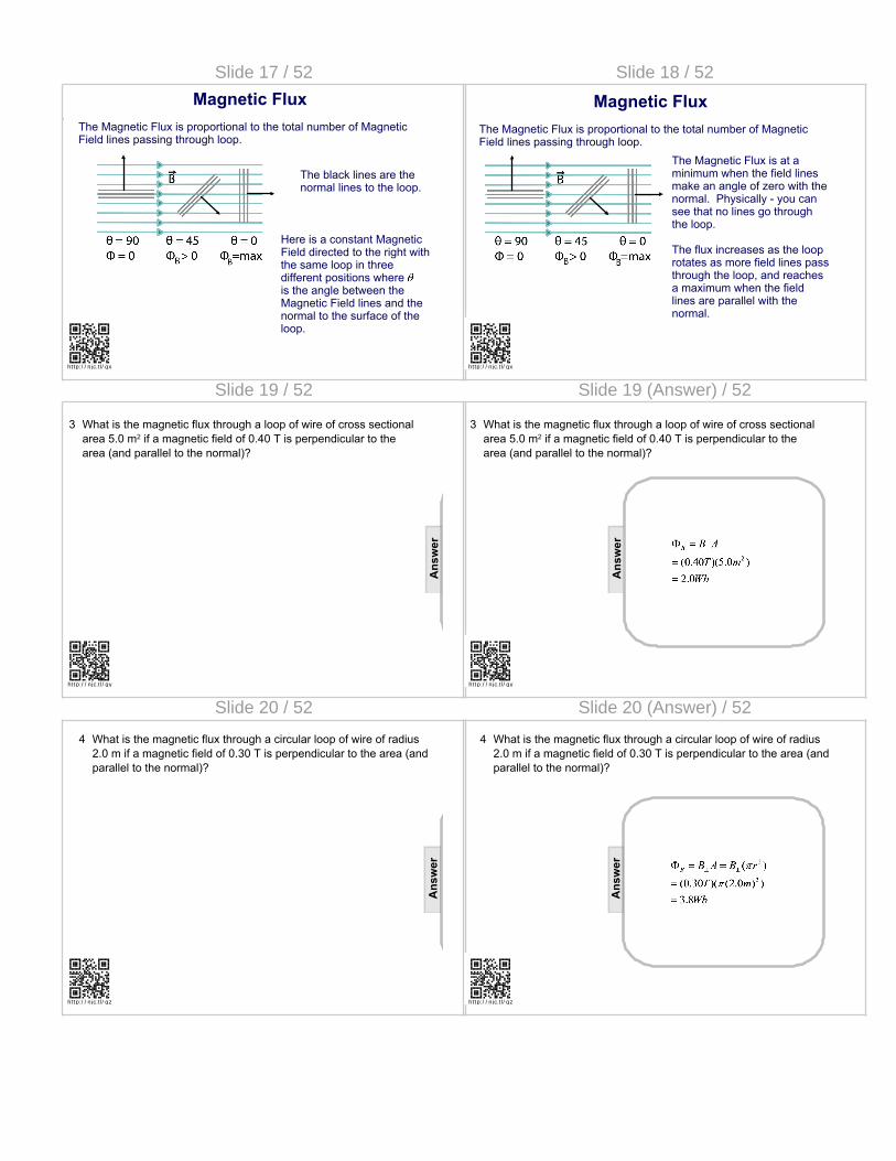
3 What is the magnetic flux through a loop of wire of cross sectional area 5.0 m2 if a magnetic field of 0.40 T is perpendicular to the area (and parallel to the normal)?
Ans
wer
ht tp:/ / njc.t l/ gy
Slide 19 (Answer) / 52
3 What is the magnetic flux through a loop of wire of cross sectional area 5.0 m2 if a magnetic field of 0.40 T is perpendicular to the area (and parallel to the normal)?
ht tp:/ / njc.t l/ gy
[This object is a pull tab]
Ans
wer
Slide 20 / 52
4 What is the magnetic flux through a circular loop of wire of radius 2.0 m if a magnetic field of 0.30 T is perpendicular to the area (and parallel to the normal)?
Ans
wer
ht tp:/ / njc.t l/ gz
Slide 20 (Answer) / 52
4 What is the magnetic flux through a circular loop of wire of radius 2.0 m if a magnetic field of 0.30 T is perpendicular to the area (and parallel to the normal)?
ht tp:/ / njc.t l/ gz
[This object is a pull tab]
Ans
wer

Slide 21 / 52
5 What is the magnetic flux through the loop of wire shown below? The magnetic field is 1.0 T and the area of the loop is 5.0 m2.
BN
N
ht tp:/ / njc.t l/ h0
Ans
wer
Slide 21 (Answer) / 52
5 What is the magnetic flux through the loop of wire shown below? The magnetic field is 1.0 T and the area of the loop is 5.0 m2.
BN
N
ht tp:/ / njc.t l/ h0
[This object is a pull tab]
Ans
wer
Slide 22 / 52
Faraday's Law of Induction
Return to Tableof Contents
ht tp:/ / njc.t l/ h2
Slide 23 / 52
Faraday’s Law of Induction
Michael Faraday and Joseph Henry showed that a changing current will induce an EMF which creates an electric current in a second loop. Their initial experiments showed that a changing current generates a changing magnetic field which develops an EMF and current.
What is actually changing is the Magnetic Flux.
Faraday's Law of Induction states that the induced EMF in a wire loop is proportional to the rate of change of Magnetic Flux through the loop:
ht tp:/ / njc.t l/ h2
Slide 24 / 52
Faraday’s Law of Induction
is the change of the Magnetic Flux (either the area of the loop exposed to the flux can change, or the magnitude of the Magnetic Field). is the time interval over which the flux is changing
There are a few new terms in this equation:
N is the number of loops (or turns) of wire in the coil.
The negative sign is related to the direction of the induced EMF and will be discussed later. For now, we'll focus on the magnitude of the induced EMF and will work an example problem.
ht tp:/ / njc.t l/ h2
Slide 25 / 52
Faraday’s Law of Induction Example Problem
Find the magnitude of the induced EMF in an 8.0 m2 one loop coil, if it is perpendicular to a 0.40T magnetic field that decreases to 0.0 T over a time interval of 2.0 s.
ht tp:/ / njc.t l/ h2
Slide 26 / 52
Faraday’s Law of Induction Example Problem
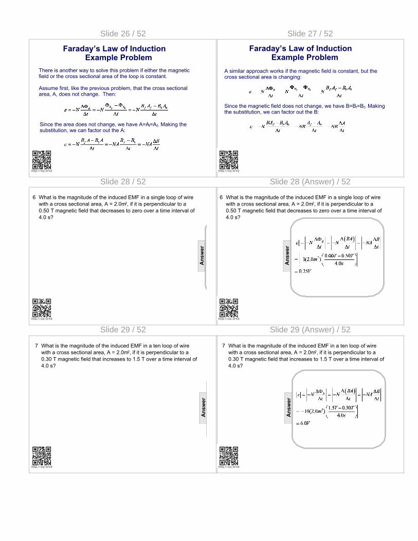
There is another way to solve this problem if either the magnetic field or the cross sectional area of the loop is constant.
Assume first, like the previous problem, that the cross sectional area, A, does not change. Then:
Since the area does not change, we have A=Af=A0. Making the substitution, we can factor out the A:
ht tp:/ / njc.t l/ h2
Slide 27 / 52
Faraday’s Law of Induction Example Problem
A similar approach works if the magnetic field is constant, but the cross sectional area is changing:
Since the magnetic field does not change, we have B=Bf=B0. Making the substitution, we can factor out the B:
ht tp:/ / njc.t l/ h2
Slide 28 / 52
6 What is the magnitude of the induced EMF in a single loop of wire with a cross sectional area, A = 2.0m2, if it is perpendicular to a 0.50 T magnetic field that decreases to zero over a time interval of 4.0 s?
Ans
wer
ht tp:/ / njc.t l/ h3
Slide 28 (Answer) / 52
6 What is the magnitude of the induced EMF in a single loop of wire with a cross sectional area, A = 2.0m2, if it is perpendicular to a 0.50 T magnetic field that decreases to zero over a time interval of 4.0 s?
ht tp:/ / njc.t l/ h3
[This object is a pull tab]A
nsw
er
Slide 29 / 52
7 What is the magnitude of the induced EMF in a ten loop of wire with a cross sectional area, A = 2.0m2, if it is perpendicular to a 0.30 T magnetic field that increases to 1.5 T over a time interval of 4.0 s?
Ans
wer
ht tp:/ / njc.t l/ h4
Slide 29 (Answer) / 52
7 What is the magnitude of the induced EMF in a ten loop of wire with a cross sectional area, A = 2.0m2, if it is perpendicular to a 0.30 T magnetic field that increases to 1.5 T over a time interval of 4.0 s?
ht tp:/ / njc.t l/ h4
[This object is a pull tab]
Ans
wer

Slide 30 / 52
So far, we've dealt with the magnetic flux changing due to the magnetic field increasing or decreasing. But how does the area of a loop change? Consider the case below where a mechanical force (somebody's hands) acts on the wire loop.
Faraday’s Law of Induction
ht tp:/ / njc.t l/ h5
Slide 31 / 52
Magnetic flux will also change if the angle between the loop and the field changes. The loop below is rotated from being perpendicular to the field, to parallel to the field. This will be covered in more detail in AP Physics when intermediate angles are analyzed.
Faraday’s Law of Induction
ht tp:/ / njc.t l/ h5
Slide 32 / 52
8 A 4.0 m2 single loop of wire is initially perpendicular to a 0.60 T magnetic field. It is then rotated so that it becomes parallel to the magnetic field 2.0 s later. Find the magnitude of the induced EMF.
ht tp:/ / njc.t l/ oq
Ans
wer
Slide 32 (Answer) / 52
8 A 4.0 m2 single loop of wire is initially perpendicular to a 0.60 T magnetic field. It is then rotated so that it becomes parallel to the magnetic field 2.0 s later. Find the magnitude of the induced EMF.
ht tp:/ / njc.t l/ oq
[This object is a pull tab]
Ans
wer
Slide 33 / 52
9 A coil consisting of 50 loops of wire is perpendicular to a 1.2 T magnetic field. The area of the coil is increased from 0.40 m2 to 1.2 m2 in 5.0 s. Find the magnitude of the induced EMF.
Ans
wer
ht tp:/ / njc.t l/ h6
Slide 33 (Answer) / 52
9 A coil consisting of 50 loops of wire is perpendicular to a 1.2 T magnetic field. The area of the coil is increased from 0.40 m2 to 1.2 m2 in 5.0 s. Find the magnitude of the induced EMF.
ht tp:/ / njc.t l/ h6
[This object is a pull tab]
Ans
wer

Slide 34 / 52
Lenz's Law
Return to Tableof Contents
ht tp:/ / njc.t l/ or
Slide 35 / 52
Now it's time to explain the minus sign in Faraday's Law. It's so important that it has its own law!
The minus sign tells us that the direction of the induced EMF ina current loop is such that the resulting current produces a magnetic field that resists the change of flux through the loop. This is a direct result of the Law of the Conservation of Energy.
If the external field gets weaker, the current tries to replace the "missing" external field. If the external field gets stronger, the induced current opposes the "extra" external field.
Only the Magnetic Field within the loop counts ; disregard the Magnetic Field outside.
Lenz’s Law
ht tp:/ / njc.t l/ or
Slide 36 / 52
. . . .. . . . . . . . . . . . . . . .
Initial External Field (red)
Final External Field
Start with a magneticfield out of the page that decreases to zero.
. . . .. . . . . . . . . . . . . . . .
This current creates a field out of the page to oppose the decrease in the external field.
The changing magnetic fieldwill induce an EMF in the loopthat will generate a current inthe counterclockwise direction.
Field due to Induced
Current (blue)
Lenz’s Law
ht tp:/ / njc.t l/ or
Slide 37 / 52
. . . .. . . . . . . . . . . . . . . .
Initial External Field (red)
Final External Field (red)
Start with no magnetic field that increases to a magnetic field out of the page.
. . . .. . . . . . . . . . . . . . . .
x x x x
x x x x x x
x x x x x x
x x x x
Field due to Induced
Current (blue) and External
Field
Lenz’s Law
This current creates a field into the page to oppose the increase in the external field.
The changing magnetic fieldwill induce an EMF in the loopthat will generate a current inthe clockwise direction.
ht tp:/ / njc.t l/ or
Slide 38 / 52
There are many other situations that can be analyzed with Lenz's Law,by using the following instructions.
The Magnetic Field due to the induced current:
1. Points in the opposite direction to the external Magnetic Field if the external Magnetic Flux is increasing.2. Points in the original direction of the external Magnetic Field if it is decreasing.3. Is zero if the flux is not changing (it is zero because of Faraday's Law - there is no induced EMF if the Magnetic Flux is constant).
Remember that the external Magnetic Field and the Magnetic Field due to the induced current are different.
Lenz’s Law
ht tp:/ / njc.t l/ or
Slide 39 / 52
Have you ever noticed that when you unplug an appliance that isrunning, there is a spark that jumps between the wall socket and the plug?
This is explained by Lenz's Law.
As the plug is pulled out, the current decreases, collapsing its MagneticField. The power source (the publicutility) attempts to boost this Magnetic Field by increasing the current; hence the spark. This is one reasonwhy you should always turn off appliances before you unplug them.
Lenz’s Law
ht tp:/ / njc.t l/ or

Slide 40 / 52
10 A magnetic field is pointing straight up through a coil of wire. The field is switched off. What is the direction of the induced current in the wire loop?
A Out of the page.
B Into the page.
C Clockwise.
D Counter-clockwise.
E There is no induced current.
Ans
wer
ht tp:/ / njc.t l/ h7
Slide 40 (Answer) / 52
10 A magnetic field is pointing straight up through a coil of wire. The field is switched off. What is the direction of the induced current in the wire loop?
A Out of the page.
B Into the page.
C Clockwise.
D Counter-clockwise.
E There is no induced current.
ht tp:/ / njc.t l/ h7
[This object is a pull tab]
Ans
wer
D
Slide 41 / 52
11 A magnetic field is pointing straight up through a coil of wire. The field is doubled in magnitude. What is the direction of the induced current in the wire loop?
A Out of the page.
B Into the page.
C Clockwise.
D Counter-clockwise.
E There is no induced current. Ans
wer
ht tp:/ / njc.t l/ h8
Slide 41 (Answer) / 52
11 A magnetic field is pointing straight up through a coil of wire. The field is doubled in magnitude. What is the direction of the induced current in the wire loop?
A Out of the page.
B Into the page.
C Clockwise.
D Counter-clockwise.
E There is no induced current.
ht tp:/ / njc.t l/ h8
[This object is a pull tab]
Ans
wer
C
Slide 42 / 52
12 A coil of wire is sitting on a table top. A magnet is held above it with its North Pole pointing downwards. What is the direction of the induced current in the coil of wire?
A Out of the page.
B Into the page.
C Clockwise.
D Counter-clockwise.
E There is no induced current.
Ans
wer
ht tp:/ / njc.t l/ h9
Slide 42 (Answer) / 52
12 A coil of wire is sitting on a table top. A magnet is held above it with its North Pole pointing downwards. What is the direction of the induced current in the coil of wire?
A Out of the page.
B Into the page.
C Clockwise.
D Counter-clockwise.
E There is no induced current.
ht tp:/ / njc.t l/ h9
[This object is a pull tab]
Ans
wer
E
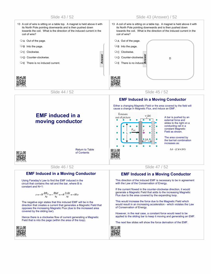
Slide 43 / 52
13 A coil of wire is sitting on a table top. A magnet is held above it with its North Pole pointing downwards and is then pushed down towards the coil. What is the direction of the induced current in the coil of wire?
A Out of the page.
B Into the page.
C Clockwise.
D Counter-clockwise.
E There is no induced current. Ans
wer
ht tp:/ / njc.t l/ ha
Slide 43 (Answer) / 52
13 A coil of wire is sitting on a table top. A magnet is held above it with its North Pole pointing downwards and is then pushed down towards the coil. What is the direction of the induced current in the coil of wire?
A Out of the page.
B Into the page.
C Clockwise.
D Counter-clockwise.
E There is no induced current.
ht tp:/ / njc.t l/ ha
[This object is a pull tab]
Ans
wer
D
Slide 44 / 52
EMF induced in a moving conductor
Return to Tableof Contents
ht tp:/ / njc.t l/ hb
Slide 45 / 52
EMF Induced in a Moving ConductorEither a changing Magnetic Field or the area covered by the field will cause a change in Magnetic Flux, and induce an EMF.
Fext
A bar is pushed by an external force and slides to the right on a conducting rail in a constant Magnetic Field as shown.
The area covered by the bar/rail combination increases as:
ht tp:/ / njc.t l/ hb
Slide 46 / 52
EMF Induced in a Moving ConductorUsing Faraday's Law to find the EMF induced in the circuit that contains the rail and the bar, where B is constant and N=1:
The negative sign states that this induced EMF will be in the direction that creates a current that generates a Magnetic Field that opposes the increasing Magnetic Flux (due to the increased area covered by the sliding bar).
Hence there is a clockwise flow of current generating a Magnetic Field that is into the page (within the area of the loop).
ht tp:/ / njc.t l/ hb
Slide 47 / 52
EMF Induced in a Moving ConductorThis direction of the induced EMF is necessary to be in agreement with the Law of the Conservation of Energy.
If the current flowed in the counter-clockwise direction, it would generate a Magnetic Field that adds to the increasing Magnetic Flux due to the area covered by the expanding loop.
This would increase the force due to the Magnetic Field which would result in an increasing acceleration - which violates the Law of Conservation of Energy.
However, in the real case, a constant force would need to be applied to the sliding bar to keep it moving and generating an EMF.
The next few slides will show the force derivation of the EMF.
ht tp:/ / njc.t l/ hb

Slide 48 / 52
EMF Induced in a Moving Conductor
Magnetic Force
Electric Force
The rod is pushed to the right. Using the right hand rule, there is a Magnetic Force on the positive charges in the downward direction. This now separates the charges in the rod (positive on the bottom, negative on the top) which creates an Electric Field, and hence force from bottom to top.
If the rod is moving at a constant v, and the charges are at equilibrium, then we have by Newton's Second Law:
ht tp:/ / njc.t l/ hb
Slide 49 / 52
EMF Induced in a Moving Conductor
Magnetic Force
Electric Force
L
Continuing the derivation:
The two ends of the bar produce a constant ElectricField so
Making the substitution:
ht tp:/ / njc.t l/ hb
Slide 50 / 52
EMF Induced in a Moving Conductor
I
Now to find the direction of the induced current in the loop. The bar has a net positive charge at the bottom and a net negative charge at the top. When the two rails are connected by the vertical wire, current will flow through this wire in a clockwise direction.
This is the same result we obtained with Faraday's Law.
ht tp:/ / njc.t l/ hb
Slide 51 / 52
14 What is the magnitude of the induced EMF between the ends of a 1.0 m rod traveling at 4.0 m/s perpendicularly to a 5.0x10⁻⁴ T magnetic field?
ht tp:/ / njc.t l/ hc
Ans
wer
Slide 51 (Answer) / 52
14 What is the magnitude of the induced EMF between the ends of a 1.0 m rod traveling at 4.0 m/s perpendicularly to a 5.0x10⁻⁴ T magnetic field?
ht tp:/ / njc.t l/ hc
[This object is a pull tab]
Ans
wer
Slide 52 / 52
15 What is the magnitude of the current in a loop containing a 100 Ω resistor and consisting of two conducting rails with a sliding 1.0 m rod traveling at 4.0 m/s perpendicularly to a 5.0x10⁻⁴ T magnetic field?
Ans
wer
ht tp:/ / njc.t l/ hd

Slide 52 (Answer) / 52
15 What is the magnitude of the current in a loop containing a 100 Ω resistor and consisting of two conducting rails with a sliding 1.0 m rod traveling at 4.0 m/s perpendicularly to a 5.0x10⁻⁴ T magnetic field?
ht tp:/ / njc.t l/ hd
[This object is a pull tab]
Ans
wer