Indice D - Motori autofrenanti Index D - Brake motors · arrangement of the motor. Only the...
24
Index D - Brake motors 1. GENERAL SPECIFICATIONS ................................. D-2 1.1 Characteristics ............................................................D-2 2. POWERS AND ELECTRIC DATA .......................... D-5 2.1. JMK 63...160 and GMK 180...250 - 2 poles....................D-5 2.2. JMK 63...160 and GMK 180...250 - 4 poles....................D-6 2.3. JMK 63...160 and GMK 180...250 - 6 poles....................D-7 2.4. JMK 71...160 and GMK 180...250 - 8 poles....................D-8 3. DIMENSIONS AND STANDARDIZED ..................... D-9 3.1. JMK 63...160 ..............................................................D-9 3.2. GMK 180...250.......................................................... D-11 4. BRAKE CHARACTERISTICS ................................. D-13 4.1. General specifications ................................................ D-13 4.2. Series TA ................................................................. D-14 4.3. Series TC ................................................................. D-15 4.4 Intorq brake series L7 .............................................. D-15 5. INSTALLATION AND MAINTENANCE ................ D-16 5.1. General directions ..................................................... D-16 5.2. Safety warning.......................................................... D-16 5.3. Connections and regulations ...................................... D-18 5.4. Periodical motor maintenance .................................... D-22 5.5. Spare parts of the brake ............................................ D-23 Indice D - Motori autofrenanti 1. CARATTERISTICHE GENERALI ............................. D-2 1.1. Caratteristiche ............................................................D-2 2. POTENZE E DATI ELETTRICI ................................ D-5 2.1. JMK 63...160 e GMK 180...250 - 2 poli ..........................D-5 2.2. JMK 63...160 e GMK 180...250 - 4 poli ..........................D-6 2.3. JMK 63...160 e GMK 180...250 - 6 poli ..........................D-7 2.4. JMK 71...160 e GMK 180...250 - 8 poli ..........................D-8 3. DIMENSIONI E NORMALIZZATI ........................... D-9 3.1. JMK 63...160 ..............................................................D-9 3.2. GMK 180...250.......................................................... D-11 4. CARATTERISTICHE DEI FRENI ........................... D-13 4.1. Caratteristiche generali .............................................. D-13 4.2. Serie TA ................................................................... D-14 4.3. Serie TC ................................................................... D-15 4.4. Freni Intorq serie L7 ................................................. D-15 5. INSTALLAZIONE E MANUTENZIONE................... D-16 5.1. Condizioni generali .................................................... D-16 5.2. Avvertenze sulla sicurezza ......................................... D-16 5.3. Collegamenti e regolazioni ......................................... D-18 5.4. Manutenzione periodica dei freni ................................ D-22 5.5. Ricambio freni .......................................................... D-23
Transcript of Indice D - Motori autofrenanti Index D - Brake motors · arrangement of the motor. Only the...

Index D - Brake motors
1. GENERAL SPECIFICATIONS .................................D-21.1 Characteristics ............................................................D-22. POWERS AND ELECTRIC DATA ..........................D-52.1. JMK 63...160 and GMK 180...250 - 2 poles ....................D-52.2. JMK 63...160 and GMK 180...250 - 4 poles ....................D-62.3. JMK 63...160 and GMK 180...250 - 6 poles ....................D-72.4. JMK 71...160 and GMK 180...250 - 8 poles ....................D-83. DIMENSIONS AND STANDARDIZED .....................D-93.1. JMK 63...160 ..............................................................D-93.2. GMK 180...250 ..........................................................D-114. BRAKE CHARACTERISTICS .................................D-134.1. General specifi cations ................................................D-134.2. Series TA .................................................................D-144.3. Series TC .................................................................D-154.4 Intorq brake series L7 ..............................................D-155. INSTALLATION AND MAINTENANCE ................D-165.1. General directions .....................................................D-165.2. Safety warning ..........................................................D-165.3. Connections and regulations ......................................D-185.4. Periodical motor maintenance ....................................D-225.5. Spare parts of the brake ............................................D-23
Indice D - Motori autofrenanti
1. CARATTERISTICHE GENERALI .............................D-21.1. Caratteristiche ............................................................D-22. POTENZE E DATI ELETTRICI ................................D-52.1. JMK 63...160 e GMK 180...250 - 2 poli ..........................D-52.2. JMK 63...160 e GMK 180...250 - 4 poli ..........................D-62.3. JMK 63...160 e GMK 180...250 - 6 poli ..........................D-72.4. JMK 71...160 e GMK 180...250 - 8 poli ..........................D-83. DIMENSIONI E NORMALIZZATI ...........................D-93.1. JMK 63...160 ..............................................................D-93.2. GMK 180...250 ..........................................................D-114. CARATTERISTICHE DEI FRENI ...........................D-134.1. Caratteristiche generali ..............................................D-134.2. Serie TA ...................................................................D-144.3. Serie TC ...................................................................D-154.4. Freni Intorq serie L7 .................................................D-155. INSTALLAZIONE E MANUTENZIONE...................D-165.1. Condizioni generali ....................................................D-165.2. Avvertenze sulla sicurezza .........................................D-165.3. Collegamenti e regolazioni .........................................D-185.4. Manutenzione periodica dei freni ................................D-225.5. Ricambio freni ..........................................................D-23

D-2
JMK - GMK
The brake motor is not included in the EU regulation n.640/2009 and n.4/2014.
1. GENERAL SPECIFICATIONS
1.1 CharacteristicsSize:Series JMK 63…160; 0,12…18,5 kW; 2, 4, 6, 8 poles;Series GMK 180…250; 11…55 kW; 2-4-6-8 poles;in 3 types:- with alternating current brake: AC brake series TA…- with direct current brake: DC brake series TC…- with Intorq direct current brake: series L7…Standard asynchronous three-phase brake motor with short circuit squirrel-cage rotor, for general purposes in industrial applications. Totally enclosed, externally fan–cooled (method of cooling IC 411), thermal insulation class F (motor-temperature rise class B).Motor designed to work in continuous running duty (S1) at rated voltage and frequency.Ambient air temperature: –15 ÷ +40°C.Maximum altitude: 1000 m above sea level.
Protection degree:- Protection-degree of the motor-enclosure IP 55.- Protection-degree of the brake-enclosure IP 54.At request protection – degree IP55 on series TA ( not available with hand release lever).
Types of construction:- IM B3, IM B5, IM B14- combined types IM B35 (B3/B5) and IM B34 (B3/B14).Motors can also work in the corresponding types of construction with vertical shaft, when inquiring please exactly state the fi nal mounting arrangement of the motor. Only the horizontal type of construction will be indicated on the name plate of the motor.
Housing:- JMK in die-cast aluminium light alloy, with the best thermal con-
ductivity and an exceptional resistance to corrosion.Hoisting ring from size 100.
- GMK cast iron casing with eyebolt for hoisting of the motor.
Shields and fl anges:- JMK Drive-end shield or fl ange in die-cast aluminium light alloy,
bearing-bores reinforced with steel sizes 80 … 160. Drive end shield made of cast iron for added strength and durability; increased security measures continue even with the brake.
- GMK end shields and fl anges in cast iron.All shields and fl anges are with “supported” tightening attachments and are fi tted on housing with a “tight” coupling.
Feet:- JMK Aluminium feet. Possibility to mount the feet on three motor-
sides so to position the terminal-box on the required side:IM B3, B5, B35, B14, B34.Standard IM B3 motor has the terminal box on the top of the housing.
- GMK cast iron feet attached to the casing. Standard IM B3 motor has the terminal box on the top of the housing (T position), terminal box on side on request.
Terminal-box:- JMK terminal box and terminal-box cover in die-cast aluminium
light alloy ( protection IP55),Supply-cable inlet bilateral sizes 63 … 132 ( sizes 63 … 80 one hole on each side, cable gland on right side and cap on the left side; sizes 90 … 132 two holes each side,
Il motore autofrenante è escluso dal Regolamento Europeo N° 640/2009 e N°4/2014.
1. CARATTERISTICHE GENERALI
1.1. CaratteristicheGrandezze:Serie JMK 63…160; 0,12…18,5 kW; 2-4-6-8 poli;Serie GMK 180…250; 11…55 kW; 2-4-6-8 poli;in 3 versioni:- con freno in corrente alternata: serie TA… - con freno in corrente continua: serie TC… - con freno in corrente continua Intorq: serie L7… Motore elettrico autofrenante asincrono trifase normalizzato per uso generale in applicazioni industriali, con rotore a gabbia in corto circuito, chiuso, autoventilato esternamente (metodo di raffredda-mento IC 411), classe termica d’isolamento F (sovratemperatura motore classe B).Progettato per operare in servizio continuo (S1) a tensione e frequenza nominali.Temperatura aria ambiente di lavoro: –15 ÷ +40°C.Altitudine massima: 1000 m sul livello del mare.
Grado di protezione:- involucro motore IP 55.- involucro freno standard IP 54.A richiesta grado di protezione IP55 solo serie TA (non possibile in esecuzione con leva di sblocco).
Forme costruttive:- IM B3, IM B5, IM B14- forme combinate IM B35 (B3/B5) e IM B34 (B3/B14).I motori possono funzionare anche nelle corrispondenti forme co-struttive ad asse verticale, ma al momento della richiesta del motore occorre specifi carne il posizionamento esatto.Sulla targa del motore rimane indicata la forma costruttiva ad asse orizzontale.
Carcassa:- JMK in lega leggera d’alluminio pressofusa. Ottima conducibilità
termica, eccellente resistenza alla corrosione. Anello di solleva-mento a partire dalla grandezza 100.
- GMK carcassa di ghisa con golfare di sollevamento motore.
Scudi e fl ange:- JMK Scudi e fl angie lato accoppiamento in lega leggera d’alluminio
pressofusa, sedi dei cuscinetti rinforzate in acciaio grandezze 80 … 160. Scudo lato opposto accoppiamento in ghisa, per garantire maggior resistenza e durata; maggior sicurezza anche con continui interventi del freno.
- GMK scudi e fl ange di ghisa.Scudi e fl ange sono tutti con attacchi di serraggio “in appoggio” e montati sulla carcassa con accoppiamento “stretto”.
Piedi:- JMK piedi di alluminio. Possibilità di montare i piedi sui 3 lati del
motore al fi ne di avere la scatola morsettiera sul lato desiderato: IM B3, B5, B35, B14, B34. Di serie il motore IM B3 è fornito con scatola morsettiera in alto.
- GMK piedi di ghisa solidali alla carcassa. Di serie il motore IMB3 è fornito con scatola morsettiera in alto, laterale a richiesta.
Scatola morsettiera:- JMK Scatola morsettiera e coperchio coprimorsettiera in lega leg-
gera d’alluminio pressofusa (protezione IP 55), con accesso cavi bilaterale dalla grandezza 63 … 132: (grandezze 63 … 80 un foro per parte, pressacavo lato destro e tappo lato sinistro; grandezze

D-3
JMK - GMK
JMK
GM
K
Tab. 1.1 / Tab. 1.1
two cable glands on right side and two caps on the left side). On size 160 two cable glands standard on the right side, at request on the left side.
- GMK terminal box and terminal-box cover in steel (terminal box adjustable through 90° turns). Cable entrance on right side.
Earth-terminal is positioned inside the terminal box; additional terminal external to the frame is serial for JMK, on request for GMK.
Terminal-block for motor-supply has 6 studs.
Standard supply of the brake separate from the one of the mo-tor. Series TA with auxiliary terminal box, series TC, L7, with rectifi er. Both positioned inside the terminal box of the motor. In series GMK both positioned in an auxiliary box. For brake-connection please see “Installation and maintenance of brakes”.
Bearings stiff, radial, single-crowned, double-shielded ball-bearings with life-long lubrication. Made by the best manufacturers and se-lected for the specifi c use on electric motors.Sealed bearings ZZ, 2RS or DDU with life-long lubrication (lithium grease – operating temperature: -15 ... +110°C) no need of main-tenance.
Carbon-steel driving shaft: cylindrical shaft ends with A-shape (rounded) key and tapped butt-end hole .The driving shaft is axially fastened by means of two elastic rings (one on the shaft and one on the rear shield).
Cooling fan is a bi-directional, radial-vane fan in resistant to high temperatures plastic material and is tightly fi xed to the motor-shaft.
Stator-winding is made with double-coated class-H copper-wire. Impregnation-system made with high-quality class-H resins. Accurate insulation of phase-windings (in each slot and on the winding-top), accurate insulation of the winding-leads (phase-beginning leads).Other insulating materials are in class F or H.
90 … 132 due fori per parte, due pressacavi lato destro e due tappi lato sinistro). Nella grandezza 160 standard due pressacavi lato destro, a richiesta lato sinistro.
- GMK Scatola morsettiera e coperchio coprimorsettiera in acciaio (scatola morsettiera orientabile di 90° in 90°). Entrata cavi d’ali-mentazione lato destro.
Morsetto di terra posizionato all’interno della scatola morsettiera; morsetto supplementare esterno sulla carcassa di serie per JMK, a richiesta per GMK.
Morsettiera per alimentazione motore a 6 morsetti.
Alimentazione freno separata: serie TA con morsettiera ausiliaria, serie TC, L7, con raddrizzatore entrambi posizionati all’interno della scatola morsettiera motore. Per serie GMK sono posizionati in una scatola ausiliaria. Per collegamento freno vedere “Installazione e manutenzione freni”.
Cuscinetti radiali rigidi a sfere ad una corona, doppio schermo lu-brifi cati a vita, delle migliori marche e selezionati per l’uso specifi co sui motori elettrici.I cuscinetti schermati ZZ, 2RS o DDU sono lubrifi cati a vita (grasso al Litio - temperatura di lavoro: -15 ... +110°C) e quindi non richie-dono manutenzione.
Albero motore in acciaio al carbonio con estremità cilindriche, foro fi lettato in testa e linguetta di forma A unifi cati. Albero motore bloccato assialmente mediante due anelli elastici (uno sull’albero, l’altro sullo scudo posteriore).
Ventola di raffreddamento calettata sull’albero motore, bidi-rezionale a pale radiali, in materiale plastico resistente alle alte temperature.
Avvolgimento statorico realizzato mediante fi lo di rame in clas-se H a doppio smalto. Sistema di impregnazione con resine di alta qualità in classe H.Accurata separazione degli avvolgimenti di fase (in cava e in testata), accurato isolamento della “trecciola” (cavi di inizio fase).Gli altri materiali sono in classe F o H.

D-4
JMK - GMK
Final insulating system of the complete motor is in class F.Materials and type of impregnation allow use in tropical climates without further treatments.
Rotor: short circuit squirrel-cage rotor in pressure die-cast alumi-nium.
Dynamic rotor balancing with a half key fi tting in the driving shaft.
Painting: Motors are painted with nitro-combined polish, suitable for normal industrial environment and unaffected by further fi nishing with single-compound synthetic paints.JMK=RAL 9006 (pearl grey);GMK= RAL 5010 (blue).
Steel-sheet Fan-cover (brake-cover), in sheet steel, painted both on the outside and the inside, by powder-painting system.JMK= black;GMK= black.
Application with inverter:JMK and GMK motors are suitable for application with inverter.
Verifying calculationsNecessary verifi cations so that brake motor can satisfy application needs are:
Frequency of starting has not to exceed maximum value permis-sible by motor windings without overheatings;
Work of friction for each braking has not to exceed maximum permissible value of friction surface.
Maximum frequency of startingAs a guide, maximum frequency of starting, for a starting time between 0,5and 1 second and with direct on-line start :Sizes 63..90 = 125 starts/hSizes 100…160 = 63 starts/hSizes 160…315 = 16 starts/h
Wide range of versions, servo-ventilation, encoder, thermistors or bimetallic thermal sensors, etc. (see “Special executions and acces-sories” page E-2).
Il sistema d’isolamento complessivo è in classe F.Materiali utilizzati e tipo di impregnazione consentono l’impiego in clima tropicale senza ulteriori trattamenti.
Rotore a gabbia di scoiattolo in corto circuito in alluminio pres-sofuso.
Equilibratura dinamica rotore con mezza linguetta inserita nell’estremità dell’albero.
Verniciatura: motore verniciato con smalto nitro combinato, idoneo a resistere ai normali ambienti industriali e a consentire ulteriori fi niture con vernici sintetiche monocomponente.JMK = RAL 9006 (grigio PERLA);GMK = RAL 5010 (blu).
Copriventola (coprifreno) in lamiera di acciaio, verniciato a polvere sia internamente che esternamente.JMK = nero;GMK = nero.
Funzionamento con inverter:I motori della serie JMK e GMK sono adatti al funzionamento con inverter.
Calcoli di verifi ca Le verifi che necessarie affi nché il motore autofrenante possasoddisfare le esigenze applicative consistono in:
La frequenza di avviamento non deve superare il valore massimoammesso dagli avvolgimenti, senza che si abbiano surriscaldamenti;
Il lavoro di attrito per ogni frenatura non deve superare il massimo valore ammesso.
Frequenza massima di avviamentoOrientativamente la massima frequenza di avviamento, per un tempo di avviamento tra 0,5 e 1 secondo e con inserzione diretta:Grandezza 63…90 = 125 avv/hGrandezza 100…160 = 63 avv/hGrandezza 160…315 = 16 avv/h
Ampia disponibilità di esecuzioni, servoventilazione, encoder, sonde termiche bimetalliche o a termistori, ecc. (vedere “Esecuzioni speciali e accessori” pag. E-2).

D-5
JMK - GMK
JMK
GM
K
Tab. 2.1 / Tab. 2.1
2. POWERS AND ELECTRIC DATA
2.1. JMK 63...160 and GMK 180...250 - 2 poles
2. POTENZE E DATI ELETTRICI
2.1. JMK 63...160 e GMK 180...250 - 2 poli

D-6
JMK - GMK
Tab. 2.2 / Tab. 2.2
2.2. JMK 63...160 and GMK 180...250 - 4 poles2.2. JMK 63...160 e GMK 180...250 - 4 poli
D-7
JMK - GMK
JMK
GM
K
Tab. 2.3 / Tab. 2.3
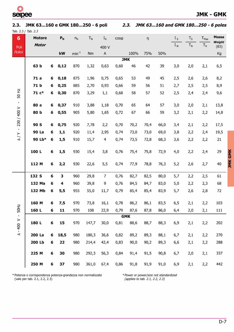
2.3. JMK 63...160 and GMK 180...250 - 6 poles
* Power or power/size not standardized (applies to tab. 2.1, 2.2, 2.3)
2.3. JMK 63...160 e GMK 180...250 - 6 poli
* Potenza o corrispondenza potenza-grandezza non normalizzate (vale per tab. 2.1, 2.2, 2.3)

D-8
JMK - GMK
Tab. 2.4 / Tab. 2.4
2.4. JMK 71...160 and GMK 180...250 - 8 poles2.4. JMK 71...160 e GMK 180...250 - 8 poli

D-9
JMK - GMK
JMK
GM
K
B14
Dis. 3.1 / Draw. 3.1
Estremità d’alberoShaft end
B3
B5
Tab. 3.1 / Tab. 3.1
3. DIMENSIONS AND STANDARDIZED
3.1. JMK 63...160
3. DIMENSIONI E NORMALIZZATI
3.1. JMK 63...160

D-10
JMK - GMK
Tab. 3.2 / Tab. 3.2

D-11
JMK - GMK
JMK
GM
K
B14
Dis. 3.2 / Draw. 3.2
Estremità d’alberoShaft end
B3
B5
Tab. 3.3 / Tab. 3.3
3.2. GMK 180...2503.2. GMK 180...250

D-12
JMK - GMK
Tab. 3.4 / Tab. 3.4

D-13
JMK - GMK
JMK
GM
K
4. BRAKE CHARACTERISTICS
4.1. General specifi cations- Alternating current brake: series TA.- Direct current brake: series TC.- Direct current Intorq brake: series L7.- Electromagnetic spring loaded brakes.- Duty type S1.- Insulation Class F, temperature-rise B.- Degree of protection IP 54; At request IP55 ( not on series TC, L7)
not available with hand release lever.- Aluminium brake-disk for the brakes TA and TC sizes 1, 2, 3, 4, 5
and L7; Steel for the brake TA, TC sizes 6, 7, 8, 9, 10.- Noise-less, asbestos-free, double friction pad.- Steel toothed dragging hub, with anti-vibration spring (except for
the L7 brake).- No axial load on the motor-shaft during braking.- High braking torque.- The braking torque is adjustable with continuity in function of the
type of use (except brake L7) please see table brake specifi cations.- Motors are supplied as a standard with brake adjusted at 80% of
the nominal braking torque (±15%) except brake L7 (see tables of brake specif.).
- On the name plate of the motor there are stated the minimum value and the nominal value of the braking torque. (brake L7 only nominal value).
- Brake is connected to an auxiliary terminal-block inside the terminal-box. Standard brake-supply: separate from the motor-supply.
- On request: hand-release lever with automatic return (release lever-rod is removable and positioned on the same side of the terminal-box).
- On request: motor pre-arranged for manual rotation of the driving shaft by means of a hexagonal-head screw-driver to be used on the non-drive end.
THE BRAKING PRINCIPLE
The brake works when it is not supplied because of the force exerted by the springs. By taking the electromagnet-supply off, the mobile anchor, pushed by the springs, presses the brake-disk, which is connected with the driving shaft, against the rear shield thus produ-cing the braking torque. By supplying the brake, the electromagnet overcomes the spring-force and attracts the mobile-anchor thus releasing the brake-disk and the driving shaft. The more-than-one-spring design and the braking starting when supply is off make the equipment safe.
SPECIFICATIONS OF THE BRAKE A.C.(see tab. 4.1 pag. D-13 - Series TA)
- High connect/disconnect speed of the braking such to allow: - A completely free start of the motor - Ahigh braking frequency- High number of brakings.- Good heat dissipation by means of the die-cast aluminum structure
and of the fan of the electric motor (S1 continuous duty can be guaranteed only with the motor ventilation).
- Mobile anchor with magnetic laminate core for a greater rapidity and lower electric losses.
- The coil is fully encased in epoxy resin.- Possibility to adjust the brake torque.- Wide range of versions, servo-ventilation, encoder, hand release
lever (see “Designs and accessories” page E-2).
This brake is suitable in any use where powerful and very quick braking is required.
4. CARATTERISTICHE DEI FRENI
4.1. Caratteristiche generali- Freno in corrente alternata: serie TA.- Freno in corrente continua: serie TC.- Freno in corrente continua Intorq: serie L7.- Freni elettromagnetici a molle.- Tipo di servizio S1.- Isolamento classe F, sovratemperatura classe B.- Grado di protezione standard IP54; a richiesta IP55 (escluse serie
TC, L7). Non possibile in esecuzione con leva di sblocco.- Disco freno in alluminio: serie TA,TC grandezza 1, 2, 3, 4, 5 e serie
L7. In acciaio: serie TA, TC grandezza 6, 7, 8, 9, 10.- Doppia guarnizione d’attrito, silenziosa, senza amianto- Mozzo trascinatore dentato in acciaio con O-ring antivibrazione
(escluso freno L7).- Nessun carico assiale sull’albero motore durante la frenatura.- Elevato momento frenante.- Possibilità di registrare il momento frenante con continuità in
funzione del tipo di impiego (escluso freno L7); vedere tabelle caratteristiche freni.
- Motori forniti di serie con freno tarato a 80% del valore nominale del momento frenante (±15%), escluso freno L7. (vedere tabella delle caratteristiche del freno).
- Sulla targa del motore sono riportati il valore minimo e il valore nominale del momento frenante (freno L7 solo il valore nominale).
- Freno collegato ad una morsettiera ausiliaria all’interno della scatola morsettiera. Di serie alimentazione freno separata.
- A richiesta: leva di sblocco manuale con ritorno automatico (asta della leva di sblocco in corrispondenza della scatola morsettiera ed asportabile).
- A richiesta: predisposizione per rotazione manuale dell’albero mo-tore mediante chiave maschio esagonale su lato opposto comando.
PRINCIPIO DI FRENATURA
Il freno agisce in mancanza dell’alimentazione per la forza esercitata dalle molle. Togliendo l’alimentazione all’elettromagnete, l’ancora mo-bile, per azione delle molle, preme il disco-freno calettato sull’albero motore contro lo scudo posteriore generando il momento frenante. Alimentando il freno, l’elettromagnete vincendo la forza delle molle, attrae l’ancora mobile e libera il disco freno e l’albero motore. La costruzione a più molle e la frenata in mancanza dell’alimentazione rendono l’apparecchiatura sicura.
CARATTERISTICHE FRENI in c.a.(Vedere tab. 4.1 pag. D-13 - Serie TA)
- Elevata velocità di inserzione e disinserzione tale da permettere: - un avviamento completamente libero del motore - un elevata frequenza di frenatura- Elevato numero di frenature.- Buona dissipazione del calore tramite la struttura ricavata da presso-
fusione di alluminio e tramite la ventola del motore elettrico (il servizio continuo S1 può essere garantito solo con la ventilazione del motore).
- Ancora mobile con nucleo magnetico lamellare per maggiore rapidità e minori perdite elettriche.
- La bobina dell’elettromagnete è completamente cementata con resina epossidica.
- Possibilità di regolare il momento frenante.- Ampia disponibilità di esecuzioni, servoventilazione, encoder, leva di
sblocco (vedere “Esecuzioni speciali e accessori” pag. E-2).
Freni consigliati per impieghi nei quali sono richieste frena-ture potenti e rapidissime.

D-14
JMK - GMK
Tab. 4.1 / Tab. 4.1
SPECIFICATIONS OF THE BRAKES D.C.(see tab. 4.2 on page D-14 - Series TC(see tab. 4.3 on page D-15 - INTORQ Series L7)
- High capacity of progressive on-off switching (both when starting and when braking) thanks to the lower rapidity of the d.c. brake.
- Maximum noise-less working.- The coil is fully encased in an epoxy resin and the mechanical
parts are protected by zinc plating.- Possibility to adjust the brake torque (except brake L7).- Wide range of versions, servo-ventilation, encoder, hand release
lever (see “Designs and accessories” page E-2).
These brakes are best suitable for use where regular, noise-less braking and start is required
4.2. Series TA
1) it is possible to reduce the braking torque, (see installation and maintenance) (except for L7 series) for safety reason do not adjust the braking torque to values lower than the minimum one stated on the name plate.
2) Standard motor is supplied to customer with braking torque adjusted at the 80% (±15%) of its nominal value.
3) ATTENTION: Air gap shall be adjusted at regular intervals! ( except for L7 series) Its value shall be included between the values stated in the table.
See “Regular maintenance of brakes”.4) Clearance “g” for the minimum value of the air-gap (for brakes
equipped with the optional release-lever).The clearance “g” decreases with the decrease of the brake disk-thickness. By adjusting the air-gap the clearance “g” is automatically reset.
CARATTERISTICHE FRENI in c.c.(vedere tab. 4.2 pag. D-14 - Serie TC)(vedere tab. 4.3 pag. D-15 - Serie Intorq L7)
- Elevata progressività d’intervento (sia all’avviamento del motore, sia in frenatura) dovuta alla minore rapidità del freno in corrente continua.
- Massima silenziosità negli interventi e nel funzionamento- La bobina dell’elettromagnete è completamente cementata con
resina epossidica e le parti meccaniche sono protette da trattamento galvanico di zincatura.
- Possibilità di regolare il momento frenante (escluso freno L7).- Ampia disponibilità di esecuzioni, servoventilazione, encoder, leva
di sblocco (vedere “Esecuzioni speciali e accessori” pag. E-2).
Freni consigliati per impieghi nei quali sono richiesti frena-ture ed avviamenti regolari e silenziosi.
4.2. Serie TA
1) È possibile ridurre il momento frenante (vedere “installazione e manutenzione freni”) (ad esclusione della serie L7). È scon-sigliato, per ragioni di sicurezza, tarare il momento frenante a valori inferiori al minimo di targa.
2) Il motore è fornito con momento frenante tarato a 80% (±15%) del suo valore nominale, oppure il motore viene fornito con momento frenante pari al valore nominale.
3) ATTENZIONE: Registrare periodicamente il traferro (ad esclu-sione della serie L7). Il suo valore deve essere sempre compreso entro i valori di tabella.
Vedere “Installazione e Manutenzione”.4) Gioco “g” per valore minimo del traferro (per freni con leva
di sblocco opzionale). Il gioco “g” si riduce al diminuire dello spessore del disco freno. Regolando il traferro si ripristina au-tomaticamente il gioco “g”.

D-15
JMK - GMK
JMK
GM
K
Tab. 4.3 / Tab. 4.3
Tab. 4.2 / Tab. 4.2
4.3. Series TC
1) it is possible to reduce the braking torque, (see installation and maintenance) (except for L7 series) for safety reason do not adjust the braking torque to values lower than the minimum one stated on the name plate.
2) Standard motor is supplied to customer with braking torque adjusted at the 80% (±15%) of its nominal value.
3) ATTENTION: Air gap shall be adjusted at regular intervals! ( except for L7 series) Its value shall be included between the values stated in the table.
See “Regular maintenance of brakes”.4) Clearance “g” for the minimum value of the air-gap (for brakes
equipped with the optional release-lever). The clearance “g” decreases with the decrease of the brake disk-thickness. By adjusting the air-gap the clearance “g” is automatically reset.
4.4 Series L7 Intorq
4.3. Serie TC
1) È possibile ridurre il momento frenante (vedere “installazione e manutenzione freni”) (ad esclusione della serie L7). È scon-sigliato, per ragioni di sicurezza, tarare il momento frenante a valori inferiori al minimo di targa.
2) Il motore è fornito con momento frenante tarato a 80% (±15%) del suo valore nominale, oppure il motore viene fornito con momento frenante pari al valore nominale.
3) ATTENZIONE: Registrare periodicamente il traferro (ad esclu-sione della serie L7). Il suo valore deve essere sempre compreso entro i valori di tabella.
Vedere “Installazione e Manutenzione”.4) Gioco “g” per valore minimo del traferro (per freni con leva
di sblocco opzionale). Il gioco “g” si riduce al diminuire dello spessore del disco freno. Regolando il traferro si ripristina au-tomaticamente il gioco “g”.
4.4. Serie L7 Intorq

D-16
JMK - GMK
5. INSTALLATION AND MAINTENANCE
5.1. General directionsOn receipt: verify that motor corresponds to order and that it has not been damaged during the transport. Do not put into service a damaged motor. Eyebolts on motor are suitable for lifting the motor only.In case of storing the environment must be covered, clean, dry, free from vibrations and corrosive agents. After long storing periods or stillstanding, it is necessary to measure insulation resistance between the windings and to earth by adequate instruments. Please contact us in case of temperature not included in -15 +40°C and height more than 1000 m, operations in aggressive environment or with explosion danger are not allowed.During the installation, position the motor so as to allow a free passage of air on fan side; avoid any insuffi cient air recycle that affects the heat exchange, heat sources near the motor that might affect the temperature both of cooling air and of motor for radiation.The base must be broad to guarantee fi xing solidity.Pairings: please verify that the radial/axial load correspond to the value of the table “radial/axial forces” (tab. 1.5, 1.6 page F-5, F-6). It is recommended to machine the hole of parts keyed onto shaft ends to H7 tolerances. Before mounting, clean mating surfaces thoroughly and lubricate against seizure. Assemble and disassemble with the aid of jacking screws and pullers to avoid any damages to the bearings of the motor. Please avoid the usage of the hammer. We suggest to heat eventual v-drive belts or pulleys to 60°-80°C before mounting.In case of direct pairing make sure that the driven shaft is parallel to machine shaft.In case of belt drives make sure that the driven shaft is parallel to machine shaft, v-best tension should be minimum possible in order not to damage the lasting of the bearings or cause a breaking of the shaft.The motors of JMK-GMK series are balanced half key; to avoid vibrations and imbalances it is necessary that transmissions are well balanced before coupling.
5.2. Safety warningAn incorrect installation, an improper use, the removing of protections, the disconnection of protection devices, the lack of inspections and maintenance, the inadequate connections may cause severe personal injury or property damage.When a bad working of the brake might cause damages to people, objects or to the production, the use of the brake-motor alone does not grant an adequate level of safety and it is therefore necessary to provide for additional safety measures. An incorrect adjustment of the braking torque and the lack of a regular maintenance may cause a bad working of the brake. Do not carry out any manual release when you cannot foresee the consequences of this action.The hand-release lever shall be removed during normal working of the motor so to avoid any incorrect or dangerous uses.Therefore motor must be moved, installed, put into service, handled, controlled, services and repaired exclusively by responsible skilled personnel (defi nition to IEC 364)Danger: electric rotating machines present dangerous parts: when operating they have live and rotating components with temperature higher than 50°C.
5. INSTALLAZIONE E MANUTENZIONE
5.1. Condizioni generaliRicevimento: verifi care che il motore corrisponda a quanto ordi-nato e che non abbia subito danneggiamenti durante il trasporto. Non si può mettere in servizio un motore danneggiato. I golfari eventualmente presenti nella carcassa servono al sollevamento del solo motore.Per l’eventuale giacenza in magazzino, il luogo deve essere coperto, pulito, asciutto, privo di vibrazioni e agenti corrosivi. Dopo lunghi periodi di giacenza a magazzino o lunghi periodi di inattività, si consiglia di verifi care la resistenza di isolamento tra gli avvol-gimenti e verso massa con apposito strumento. Per funzionamenti con temperatura diversa da -15 +40°C e ad altitudini superiori ai 1000 m, interpellateci. Non è consentito l’impiego in luoghi con atmosfere aggressive, con pericolo di esplosione.Nell’installazione sistemare il motore in modo che si abbia un am-pio passaggio d’aria dal lato della ventola; insuffi ciente circolazione d’aria compromette lo scambio termico. Evitare la vicinanza con altre fonti di calore tali da infl uenzare la temperatura sia dell’aria di raffreddamento che del motore per irraggiamento.La fondazione deve essere ben dimensionata per garantire stabilità al fi ssaggio.Accoppiamenti: verifi care che il carico radiale/assiale rientri nei valori riportati nelle tabelle “Forze radiali/assiali” (tab. 1.5, 1.6 pag. F-5, F-6). Per il foro degli organi calettati sull’estremità dell’albero è consigliata la tolleranza H7. Prima di eseguire l’accoppiamento pulire e lubrifi care le superfi ci di contatto per evitare pericoli di grippaggio. Nelle operazioni di montaggio (smontaggio) utilizzare sempre appositi tiranti (estrattori) per evitare eventuali danni ai cuscinetti del motore. L’uso del martello è quindi da escludere. È consigliabile riscaldare eventuali giunti, pulegge fi no a 60-80°C prima del montaggio.Nell’accoppiamento diretto curare l’allineamento del motore rispetto a quello della macchina condotta.Nell’accoppiamento a cinghia verifi care che: l’asse del motore deve essere sempre parallelo all’asse della macchina condotta, lo sbalzo della puleggia deve essere il minimo possibile, la tensione delle cinghie non deve essere eccessiva per non compromettere la durata dei cuscinetti o provocare la rottura dell’albero motore.I motori della serie JMK-GMK sono equilibrati con mezza linguet-ta; per evitare vibrazioni e squilibri è necessario che gli organi di trasmissione siano stati opportunamente equilibrati prima dell’ac-coppiamento.
5.2. Avvertenze sulla sicurezzaUn uso improprio del motore, un’installazione non corretta, la rimozione delle protezioni, l’eliminazione dei dispositivi di sicurezza, la carenza di manutenzione, possono causare gravi danni a persone e cose.Quando esiste la possibilità che un malfunzionamento del freno possa causare danni alle persone, alle cose e alla produzione, l’impiego del solo motore autofrenante non garantisce un livello di sicurezza adeguato ed è necessario predisporre misure di sicurezza supple-mentari. Una errata taratura del momento frenante e la mancanza di una manutenzione periodica possono causare un malfunzionamento del freno. Non eseguire lo sblocco manuale del freno se non si è in grado di prevedere le conseguenze di questa manovra. L’asta della leva di sblocco non deve essere lasciata installata permanentemente sul freno durante il funzionamento del motore per evitarne utilizzi inopportuni e pericolosi.Pertanto deve essere movimentato, installato, messo in servizio, curato e riparato esclusivamente da personale qualifi cato (secondo IEC364). Pericoli: i motori elettrici presentano parti poste sotto tensione, parti in movimento, parti con temperature superiori a 50°C.
D-17
JMK - GMK
JMK
GM
K
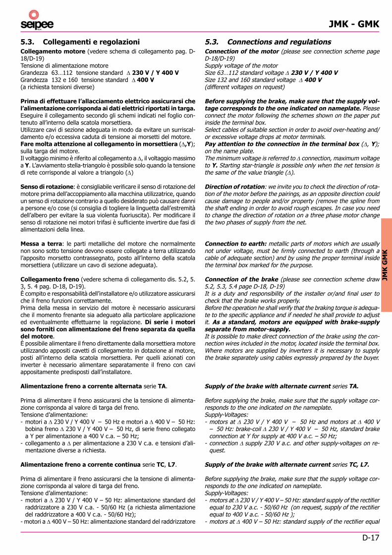
5.3. Connections and regulationsConnection of the motor (please see connection scheme page D-18/D-19)Supply voltage of the motorSize 63…112 standard voltage 230 V / Y 400 VSize 132 and 160 standard voltage 400 V(different voltages on request)
Before supplying the brake, make sure that the supply vol-tage corresponds to the one indicated on nameplate. Please connect the motor following the schemes shown on the paper put inside the terminal box.Select cables of suitable section in order to avoid over-heating and/or excessive voltage drops at motor terminals.Pay attention to the connection in the terminal box (, Y); on the name plate.The minimum voltage is referred to connection, maximum voltage to Y. Starting star-triangle is possible only when the net tension is the same of the value triangle ().
Direction of rotation: we invite you to check the direction of rota-tion of the motor before the pairings, as an opposite direction could cause damage to people and/or property (remove the spline from the shaft ending in order to avoid rough escapes. In case you need to change the direction of rotation on a three phase motor change the two phases of supply from the net.
Connection to earth: metallic parts of motors which are usually not under voltage, must be fi rmly connected to earth (through a cable of adequate section) and by using the proper terminal inside the terminal box marked for the purpose.
Connection of the brake (please see connection scheme draw 5.2, 5.3, 5.4 page D-18, D-19)It is a duty and responsibility of the installer or/and fi nal user to check that the brake works properly.Before the operation he shall verify that the braking torque is adequa-te to the specifi c appliance and if needed he shall provide to adjust it. As a standard, motors are equipped with brake-supply separate from motor-supply.It is possible to make direct connection of the brake using the con-nection wires included in the motor, located inside the terminal box. Where motors are supplied by inverters it is necessary to supply the brake separately using cables expressly prepared by the buyer.
Supply of the brake with alternate current series TA.
Before supplying the brake, make sure that the supply voltage cor-responds to the one indicated on the nameplate.Supply-Voltages:- motors at 230 V / Y 400 V – 50 Hz and motors at 400 V
– 50 Hz: brake-coil 230 V / Y 400 V – 50 Hz, standard brake connection at Y for supply at 400 V a.c. – 50 Hz;
- connection supply 230 V a.c. and other supply-voltages on re-quest.
Supply of the brake with alternate current series TC, L7.
Before supplying the brake, make sure that the supply voltage cor-responds to the one indicated on nameplate.Supply-Voltages:- motors at 230 V / Y 400 V – 50 Hz: standard supply of the rectifi er
equal to 230 V a.c. - 50/60 Hz (on request, supply of the rectifi er equal to 400 V a.c. - 50/60 Hz );
- motors at 400 V – 50 Hz: standard supply of the rectifi er equal
5.3. Collegamenti e regolazioniCollegamento motore (vedere schema di collegamento pag. D-18/D-19)Tensione di alimentazione motoreGrandezza 63…112 tensione standard 230 V / Y 400 VGrandezza 132 e 160 tensione standard 400 V(a richiesta tensioni diverse)
Prima di effettuare l’allacciamento elettrico assicurarsi che l’alimentazione corrisponda ai dati elettrici riportati in targa.Eseguire il collegamento secondo gli schemi indicati nel foglio con-tenuto all’interno della scatola morsettiera.Utilizzare cavi di sezione adeguata in modo da evitare un surriscal-damento e/o eccessiva caduta di tensione ai morsetti del motore.Fare molta attenzione al collegamento in morsettiera (,Y); sulla targa del motore.Il voltaggio minimo è riferito al collegamento a , il voltaggio massimo a Y. L’avviamento stella-triangolo è possibile solo quando la tensione di rete corrisponde al valore a triangolo ()
Senso di rotazione: è consigliabile verifi care il senso di rotazione del motore prima dell’accoppiamento alla macchina utilizzatrice, quando un senso di rotazione contrario a quello desiderato può causare danni a persone e/o cose (si consiglia di togliere la linguetta dall’estremità dell’albero per evitare la sua violenta fuoriuscita). Per modifi care il senso di rotazione nei motori trifasi è suffi ciente invertire due fasi di alimentazioni della linea.
Messa a terra: le parti metalliche del motore che normalmente non sono sotto tensione devono essere collegate a terra utilizzando l’apposito morsetto contrassegnato, posto all’interno della scatola morsettiera (utilizzare un cavo di sezione adeguata).
Collegamento freno (vedere schema di collegamento dis. 5.2, 5. 3, 5. 4 pag. D-18, D-19).È compito e responsabilità dell’installatore e/o utilizzatore assicurarsi che il freno funzioni correttamente.Prima della messa in servizio del motore è necessario assicurarsi che il momento frenante sia adeguato alla particolare applicazione ed eventualmente effettuarne la regolazione. Di serie i motori sono forniti con alimentazione del freno separata da quella del motore.È possibile alimentare il freno direttamente dalla morsettiera motore utilizzando appositi cavetti di collegamento in dotazione al motore, posti all’interno della scatola morsettiera. Per quelli azionati con inverter è necessario alimentare separatamente il freno con cavi appositamente predisposti dall’installatore.
Alimentazione freno a corrente alternata serie TA.
Prima di alimentare il freno assicurarsi che la tensione di alimenta-zione corrisponda al valore di targa del freno.Tensione d’alimentazione:- motori a 230 V / Y 400 V – 50 Hz e motori a 400 V – 50 Hz:
bobina freno 230 V / Y 400 V – 50 Hz, di serie freno collegato a Y per alimentazione a 400 V c.a. – 50 Hz;
- collegamento a per alimentazione a 230 V c.a. e tensioni d’ali-mentazione diverse a richiesta.
Alimentazione freno a corrente continua serie TC, L7.
Prima di alimentare il freno assicurarsi che la tensione di alimenta-zione corrisponda al valore di targa del freno.Tensione d’alimentazione:- motori a 230 V / Y 400 V – 50 Hz: alimentazione standard del
raddrizzatore a 230 V c.a. - 50/60 Hz (a richiesta alimentazione del raddrizzatore a 400 V c.a. - 50/60 Hz);
- motori a 400 V – 50 Hz: alimentazione standard del raddrizzatore

D-18
JMK - GMK
Dis. 5.2 / Draw. 5.2
Dis. 5.1 / Draw. 5.1
to 400 V a.c. 50/60 Hz (on request, supply of the rectifi er equal to 230 V a.c. - 50/60 Hz);
- other supply-voltages on request.
COMMUNITY DIRECTIVES
- “Low Voltage” directive 2014/35/UE. The motors of this catalogue comply with the requirements of the directives and show on the nameplate CE brand.
- “Electromagnetic Compatibily “ directive 2014/30/UE. Not compul-sory on the products of this catalogue. Compliance to the directive is responsibility of the builder of the machine.
We remind that: electric motors are components which shall not be started for duty unless installed on a machine (or complete sy-stem) which must comply and must be declared to comply with the “Machine directive” 2006/42/CEE.
Connection scheme terminal box three phase motor 2- 4- 6- 8 poles
Connection of the a.c. brake series TA
1) Sizes 63…112 standard supply 230 V / Y 400 V – 50 Hz.
Sizes 132...160 standard supply of the motor 400 V – 50 Hz.
a 400 V c.a. 50/60 Hz. (a richiesta alimentazione del raddrizzatore pari a 230 V c.a. - 50/60 Hz.);
- tensioni d’alimentazione diverse a richiesta.
DIRETTIVE COMUNITARIE
- Direttiva “Bassa Tensione” 2014/35/UE. I motori del presente ca-talogo sono conformi alla direttiva e riportano in targa il marchio CE.
- Direttiva “Compatibilità Elettromagnetica” 2014/30/UE. Non obbli-gatoriamente applicabile ai prodotti di questo catalogo. La respon-sabilità della conformità alla direttiva è a carico del costruttore della macchina.
Ricordiamo inoltre che il motore elettrico è un componente che non deve essere posto in servizio prima di essere installato in una macchina (o sistema completo) resa e dichiarata conforme alle di-sposizioni della “Direttiva Macchine” 2006/42/CEE.
Schema collegamento morsettiera motore trifase 2-4-6-8 poli
Collegamento freno a corrente alternata serie TA
1) Grandezza 63...112 alimentazione standard motore 230 V - Y 400 V – 50 Hz.
Grandezza 132...160 alimentazione standard motore 400 V – 50 Hz.

D-19
JMK - GMK
JMK
GM
K
Dis. 5.3 / Draw. 5.3
Dis. 5.4 / Draw. 5.4
Connection of the D.C. brake type TC, L7.
1) Motors are supplied with rectifi er connected to the auxiliary terminal box (112…250 terminal box fi xed on the rectifi er). On request connection of the rectifi er to terminal box of the motors.
2) Fast braking (on charge of the installer). On request on sizes 90, 100. Brake supply contactor should work in parallel with motor supply contactor; the contacts should be suitable to open very inductive loads.
Collegamento freno a corrente continua serie TC, L7.
1) I motori vengono forniti con il raddrizzatore collegato alla mor-settiera ausiliaria (112...250 morsettiera integrata nel raddrizza-tore). A richiesta collegamento del raddrizzatore a morsettiera motore.
2) Frenata rapida (a cura dell’installatore). Grandezza motore 90, 100 a richiesta. Il contattore di alimentazione freno deve lavo-rare in parallelo con il contattore di alimentazione del motore; i contatti debbono essere idonei all’apertura di carichi fortemente induttivi.

D-20
JMK - GMK
Tab. 5.1 / Tab. 5.1
Braking torque adjustment (except brake series L7)
Standard motor is supplied to customer with braking torque adjusted at the 80% (±15%) of its nominal value. (series L7 100%). For a good operation, adjust the braking torque according to the speci-fi cations of the load, rotation speed and braking time. For general uses it is advisable to adjust the braking torque at about 1,5 times the driving torque of the motor.In any case the braking torque shall be included in the limits written on the nameplate. It is unadvisable to adjust the brake torque to a value higher than the maximum of the name plate (brake may not release or release partially causing vibrations and heating), or lower than the minimum of the name plate (risk of changeful braking).The braking torque is directly proportional to the spring-compression.
Series TA: turn the grub-screws (3) (drawing page D-23) positioned on the rear end of the brake-structure by means of a hexagonal head screw driver. Take care of turning all grub-screws in a uniform way (rotation clockwise increase, rotation anti-clockwise decrease). Check the adjustment- value of the braking torque by using a dynamometric key inserted in the motor shaft-end.On TA series it is possible to check roughly the value of the braking torque obtained with the regulation, measuring the distance between regulation screw and electromagnet (letter “A” [mm] see following table and drawing on page D-23).
Regolazione del momento frenante (escluso freno serie L7)
Il motore è fornito con momento frenante tarato al 80% ±15% del suo valore nominale (serie L7 al 100%). Per un corretto impiego del motore autofrenante è consigliabile regolare il momento frenante in funzione del carico, della velocità di rotazione e del tempo di frenata. Per impieghi generici è buona norma tarare il momento frenante a circa 1,5 volte il momento torcente nominale del motore.In ogni caso il valore deve essere compreso fra i limiti ripor-tati in targa. È sconsigliato: tarare il momento frenante ad un valore superiore al massimo di targa (il freno può non sbloccarsi o sbloccarsi solo parzialmente con conseguenti vibrazioni e surriscalda-mento), tarare il momento frenante ad un valore inferiore al minimo di targa (si possono avere delle frenature incostanti).Il momento frenante è direttamente proporzionale alla compressione delle molle.
Serie TA: ruotare le viti (3) (disegno pag. D-23) di regolazione momento frenante in modo uniforme, con chiave maschio esago-nale (rotazione oraria, aumenta; rotazione antioraria diminuisce). Verifi care il valore di taratura del momento frenante utilizzando una chiave dinamometrica accoppiata all’estremità dell’albero motore.Nella serie TA è possibile conoscere in modo approssimativo il valore del momento frenante ottenuto dopo la regolazione, misurando la distanza (evidenziata con la lettera “A” [mm] vedere tabella seguente e disegno pag. D-23) tra la vite di regolazione e l’elettromagnete.

D-21
JMK - GMK
JMK
GM
K
Tab. 5.2 / Tab. 5.2
Series TC: You can provide for the adjustment of the braking torque by turning the bush (3) (drawing page D-23) that controls the compression of the spring. Check the adjustment-value of the braking torque by using a dynamometric key inserted in the motor shaft-end. Should the braking torque be lower than the minimum stated value, unsteady braking might occur. And more, the number of the gripping threads in the adjustment-bush are not enough and the threads could easily break up.It is possible to check roughly the value of the braking torque ob-tained with the regulation.Series TC measure the distance (letter “B” [mm] see following table and drawing on page D-23) between regulation nut and elec-tromagnet.
Important: before starting the group motor-brake it is important to: check the right fi xing of the studs, of the stud to earth, close the terminal box placing the gasket correctly and screwing all the fi xing screws of the cover (to maintain the protection degree shown on the name plate), mount the fan cover and fi x with its screws, check the mechanic fi xing of the pairings and mount eventual protections (protection carter).
Serie TC: ruotare la ghiera (3) (disegno pag. D-23) di regolazione momento frenante (rotazione oraria, aumenta; rotazione antioraria diminuisce). Verifi care il valore di taratura del momento frenante utilizzando una chiave dinamometrica accoppiata all’estremità dell’albero motore. Per valori inferiori al minimo di targa il numero di fi letti in presa della ghiera di regolazione risulta insuffi ciente; la ghiera potrebbe staccarsi.È possibile conoscere in modo approssimativo il valore del momento frenante ottenuto dopo la regolazione.Serie TC: si misura la distanza (evidenziata con la lettera “B” [mm] vedere tabella seguente e disegno pag. D-23) tra la ghiera di rego-lazione e l’elettromagnete.
Importante: prima della messa in servizio del gruppo motore-freno occorre: verifi care il corretto serraggio dei morsetti elettrici, del morsetto di terra, richiudere la scatola morsettiera posizionando correttamente la guarnizione e avvitando tutte le viti di fi ssaggio del coperchio (per non alterare il grado di protezione dichiarato in targa), rimontare il copriventola e fi ssarlo con le apposite viti, controllare il fi ssaggio meccanico degli organi di trasmissione accoppiati e rimon-tare eventuali protezioni (carter di protezione).

D-22
JMK - GMK
5.4. Periodical motor maintenance
The operation of service on the brake must be done only when the brake is not electrically connected and the connection to earth is verifi ed.Check periodically that the air gap value is inside the values of the relative tables (see chapter “brake specifi cations”). If the air gap is too high the brake will be less silent and it may occur that the brake is not released.Furthermore, should the braking torque be higher than the allowable maximum value, it might occur that:- the torque decreases- a total absence of braking due to the disappearance of clearance
“g” on the hand release (on motors with the optional hand release lever); regulating the air gap the clearance “g” is automatically reset
- partial release thus producing temperature-rise and wear of the friction gasket.
Air gap adjustmentAir gap adjustment
Series TA (draw. page D-23)- loosen the nuts (10) locking the brake-studs (1) to the cast-iron
shield of the motor- screw the brake-studs up (10) maintaining the nuts still, until you
get the minimum air gap ( see chapter “ brake specifi cations”)- while holding the studs (10) , tighten up their locking nuts (1),- check the air gap near the studs by means of a thickness-gauge.
Series TC (draw. page D-23)- loosen the nuts (1) locking the brake-studs (10) to the cast-iron
shield of the motor- turn the registers (10) that regulate the air gap until you get the
minimum air gap (see chapter “ brake specifi cations”);- while holding the registers (10), tighten up their screws (1)- check the air gap near the studs by means of a thickness-gauge.
Brake diskVerify the thickness of the friction gasket on both sides. This value cannot be less than 1 mm each side. If necessary please replace the brake disk.
Hand release lever.In case the hand release lever does not release the brake, reset the clearance “g” indicated in the table (see chapter “BRAKE CHA-RACTERISTICS”).
After the operations we suggest to remove always the lever.
5.4. Manutenzione periodica dei freni
Le operazioni di ispezione del freno devono essere eseguite a freno elettricamente scollegato e dopo aver verifi cato il collegamento di messa a terra.Verifi care periodicamente che il traferro sia compreso entro i valori indicati nelle rispettive tabelle (vedere capitolo “caratte-ristiche freni”); un traferro eccessivo rende il freno meno silenzioso e può impedire lo sbloccaggio del freno stesso.Inoltre un traferro superiore al valore massimo può produrre:- una diminuzione del momento frenante- una mancanza totale di frenatura dovuta all’annullamento del gioco
“g” dei tiranti della leva di sblocco (per freni con leva di sblocco opzionale); regolando il traferro si ripristina automaticamente il gioco “g”
- un parziale sbloccaggio del freno con conseguente aumento della temperatura e dell’usura della guarnizione di attrito.
Regolazione del traferro
Serie TA (dis. pag. D-23)- allentare i dadi (10) che bloccano le viti (1) di fi ssaggio del freno
allo scudo in ghisa del motore- avvitare le viti (1) mantenendo fermi i dadi (10) fi no al raggiungi-
mento del traferro minimo (vedere capitolo “caratteristiche freni”)- serrare i dadi (10) mantenendo ferme le viti (1)- verifi care il traferro ottenuto in prossimità delle colonnette utiliz-
zando uno spessimetro.
Serie TC (dis. pag. D-23)- allentare le viti (1) di fi ssaggio del freno allo scudo in ghisa del
motore- ruotare i registri (10) che regolano il traferro fi no al raggiungimento
del traferro minimo (vedere capitolo “caratteristiche freni”)- avvitare le viti (1) mantenendo fermi i registri (10)- verifi care il traferro ottenuto in prossimità delle colonnette utiliz-
zando uno spessimetro.
Disco frenoVerifi care lo spessore della guarnizione d’attrito da entrambe le parti. Tale valore non deve essere inferiore ad 1 mm per parte. All’occor-renza sostituire il disco freno.
Leva di sbloccoNel caso in cui la leva non sblocchi il freno ripristinare il gioco “g” indicato in tabella (vedere capitolo “CARATTERISTICHE DEI FRENI”).
Si consiglia sempre di asportare l’impugnatura una volta terminate le operazioni.

D-23
JMK - GMK
JMK
GM
K
Dis. 5.5 / Draw. 5.5
5.5. Spare parts of the brake
1) Fastening screw2) Electromagnet3) Regulation of the braking torque: cylindrical head screw with
hexagonal hole on series TA, regulation bush on series TC.4) Spring5) O ring for IP55 (series TA)6) Brake anchor7) Brake disk8) O ring against vibrations9) Dragging hub10) Screw for Air gap adjustment11) Protection gaiter12) Release lever (removable)13) Body14) Screw for clearance “g” adjustment
5.5. Ricambio freni
1) Vite di fi ssaggio2) Elettromagnete3) Regolazione momento frenante: vite a testa cilindrica con cava
esagonale per serie TA, ghiera di regolazione per serie TC.4) Molla di frenatura5) Anello O-ring per IP 55 (serie TA)6) Ancora freno7) Disco freno8) Anello O-ring antivibrazione9) Mozzo trascinatore10) Vite di registro traferro11) Protezione in gomma12) Impugnatura (asportabile)13) Corpo14) Vite di registro gioco “g”

D-24
JMK - GMK
Note / Notes :
__________________________________________________________________________________________
__________________________________________________________________________________________
__________________________________________________________________________________________
__________________________________________________________________________________________
__________________________________________________________________________________________
__________________________________________________________________________________________
__________________________________________________________________________________________
__________________________________________________________________________________________
__________________________________________________________________________________________
__________________________________________________________________________________________
__________________________________________________________________________________________
__________________________________________________________________________________________
__________________________________________________________________________________________
__________________________________________________________________________________________
__________________________________________________________________________________________
__________________________________________________________________________________________