INDICATIVE SITE SPECIFIC ENVIRONMENTAL MANAGEMENT …
23
INDICATIVE SITE SPECIFIC ENVIRONMENTAL MANAGEMENT PLAN (SSEMP) Central Otaki (from Chainage 1500 to 2500)
Transcript of INDICATIVE SITE SPECIFIC ENVIRONMENTAL MANAGEMENT …

INDICATIVE SITE SPECIFIC ENVIRONMENTAL MANAGEMENT PLAN
(SSEMP)
Central Otaki (from Chainage 1500 to 2500)

© Opus International Consultants Ltd 2013
Opus International Consultants Ltd Wellington Civil L7, Majestic Centre, 100 Willis St PO Box 12 003, Wellington 6144 New Zealand
Telephone: +64 4 471 7000 Facsimile: +64 4 471 1397
Date: Reference: Status:

i
| Opus International Consultants Ltd
Contents
1 Introduction ........................................................................................................1
2 Drawings .............................................................................................................1
3 Management Plans ............................................................................................. 2
3.1 Construction Works .............................................................................................................. 2
3.2 Stormwater ............................................................................................................................ 5
3.3 Erosion & Sediment Control ................................................................................................. 6
3.4 Revegetation .......................................................................................................................... 9
3.5 Water Abstraction and Dust Control ................................................................................... 9
3.6 Quarrying ............................................................................................................................. 10
3.7 Transporting of Materials ................................................................................................... 10
3.8 Ecology ................................................................................................................................. 10
3.9 Construction Air Quality ...................................................................................................... 11
3.10 Contaminated Land.............................................................................................................. 11
3.11 Construction Noise and Vibration ...................................................................................... 12
3.12 Culture and Heritage ............................................................................................................ 12
3.13 Landscape ............................................................................................................................. 12
3.14 Construction Traffic Management ...................................................................................... 12
3.15 Network Utilities .................................................................................................................. 13
4 Re-Instatement .................................................................................................14
5 Training and Monitoring ...................................................................................14
Appendix A: Drawings .......................................................................................... 15

1
1 Introduction
This SSEMP relates to those construction matters that have potential or actual effects on aspects of the local natural and human environment.
It covers the construction of a four lane highway including a new local arterial with significant cut batters, establishment of erosion and sediment control structures, installation of culverts, the formation of stream diversion, and installation of a variety of stormwater treatment devices, and post construction landscape and mitigation planting. This SSEMP covers a length of alignment of approximately 1.0 kilometres in the area of Central Otaki.
Note that the CEMP contains generic details common to the route standard details and methodologies for a range of activities such as diversions, culvert installation, sediment and
erosion control, monitoring and mitigation which are not repeated in this SSEMP.
This site specific management plan relates to those matters that are unique to this section of the alignment.
This Document, that is in the form of an SSEMP, is one of a number that have been developed for key focus areas along the proposed expressway. The focus areas were chosen to be representative of the range of sites along the route and to have between them the full range of environmental management issues likely to be encountered during construction of the route.
There are a number of consents and designation conditions that are relevant to this SSEMP, these are contained in the AEE.
2 Drawings
Refer to Appendix A of this SSEMP for Drawings A01 to A05. These drawings should be read in conjunction with this document and show the location of the proposed works, indicative construction sequencing and proposed erosion and sediment control practices.
The following drawings are included in Appendix A: • Drawing A01 - Central Otaki Stage 1 • Drawing A02 - Central Otaki Stage 2 • Drawing A03 - Central Otaki Stage 3 • Drawing A04 - Landscape Plan • Drawing A05 - Otaki Rail Station Works
2
3 Management Plans
3.1 Construction Works
3.1.1 Programme
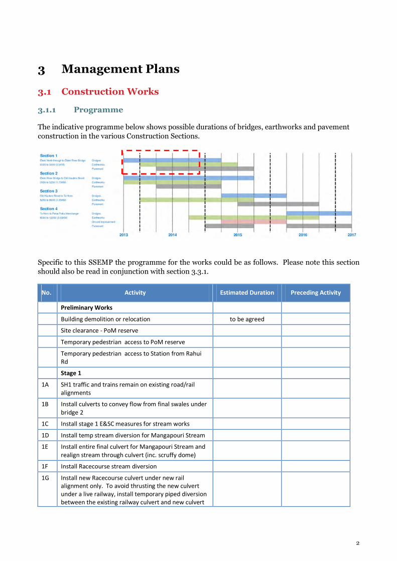
The indicative programme below shows possible durations of bridges, earthworks and pavement construction in the various Construction Sections.
Specific to this SSEMP the programme for the works could be as follows. Please note this section should also be read in conjunction with section 3.3.1.
No. Activity Estimated Duration Preceding Activity
Preliminary Works
Building demolition or relocation to be agreed
Site clearance - PoM reserve
Temporary pedestrian access to PoM reserve
Temporary pedestrian access to Station from Rahui
Rd
Stage 1
1A SH1 traffic and trains remain on existing road/rail
alignments
1B Install culverts to convey flow from final swales under
bridge 2
1C Install stage 1 E&SC measures for stream works
1D Install temp stream diversion for Mangapouri Stream
1E Install entire final culvert for Mangapouri Stream and
realign stream through culvert (inc. scruffy dome)
1F Install Racecourse stream diversion
1G Install new Racecourse culvert under new rail
alignment only. To avoid thrusting the new culvert
under a live railway, install temporary piped diversion
between the existing railway culvert and new culvert

3
(offline) and liven this diversion.
1H Construct bridges 2 & 3 and earthworks offline
1I Install E&SC measures for stage 2 earthworks
Stage 2
2A Complete tie-ins for new SH1 overbridge and realign
SH1 traffic to new bridge
2B Demolish existing SH1 ramp bridge
2C Carry out bulk earthworks to complete new rail
alignment.
2D Construct temporary realignment of Rahui Rd
including a temporary rail signalised crossing
2E Complete new rail at station – as night time operation
2F Switch rail to new alignment
2G Construct Bridge 4 (Rahui Rd)
2H Finalise construction of new Racecourse culvert.
Stage 3
3A Install E&SC measures for stage 3 main expressway
earthworks
3B Construct temporary realignment of County Road
3C Construct bridge 4 approach ramps and realign traffic
over new bridge.
3D Decommission temporary realignment of County Road
3E Decommission temporary realignment of Rahui Road
3F Construct new SH1 expressway
3G Construct Kennedy and Railway wetlands
3H Construct Taylor Basin
3I On-going maintenance of erosion and sediment
controls
3.1.2 Otaki Rail Station
Once the rail corridor earthworks have been completed up to the tie-in sections on the existing railway alignment, the North Island Main Trunk (NIMT) can then be moved to its new location. It is noted that the NIMT relocation tie-in work may need to be phased with the KiwiRail NIMT Block-of-Line programme. The historic Ōtaki Railway Station relocation works can also be undertaken at this time in accordance with an updated conservation plan and, under an authority proposed to be obtained from the Historic Places Trust. There is adequate land to the south of the existing platform and station to provide a temporary mass-bloc platform and commuter shelters while the station and platform deconstruction is undertaken and the new platform and station reconstruction works are being carried out.
The track lateral shift and tie-in will need to be programmed to suit KiwiRail track laying operations.

4
3.1.3 Pare-o-Matangi Reserve
Pare-o-Matangi Reserve is in an area of historic and cultural signifigance for the tangata whenua. As noted on a commemorative plaque within the reserve, Pare-o-Matangi Reserve was developed as a late 1990s Millennium project as a community amenity reserve by the Keep Ōtaki Beautiful group, with input from KCDC. Much of the existing reserve, as well as all of the undeveloped open space towards County Road will be removed as a result of the construction of the expressway and realigned railway.
There has been considerable consultation over the development and planting in Pare-o-Matangi Reserve, and the timing of that planting. Although this has not been fully confirmed yet, and further consultation is to be carried out, there will be a need to consider early landscape planting.
3.1.4 Earthworks
During construction the area of earthworks open will be restricted, as much as is practicable, to the road corridor. Construction will be staged (refer section 3.3) to reduce the area of earthworks open concurrently with progressive stabilisation treatment including re-vegetation to limit erosion and mobilisation of sediment.
Generally the earthworks operation in the Central Otaki area will consist of a staged cut to fill operation. Cut material will be sourced to the north of the Project area (ch 1500m to 1700m) to form fill embankments for the expressway and proposed rail line to the south.
Earthworks quantities for the Central Otaki alignment are given in the table below:
EARTHWORKS CATEGORY AREA (m2) QUANTITY (m
3)
Earthworks cut from 1,500 – 2,500m 44,000
Earthworks structural fill required from
1,500 – 2,500m
80,000
Net earthworks balance from 1,500 –
2,500m
-36,000
3.1.5 Cut & Fill Treatments
The final form and treatment of cut and fill batters has a bearing on both landscape and visual effects. In order to reduce the degree of these effects the following actions will be undertaken:
• Use of geotextile erosion matting on erodible sand dune batters to prevent erosion; • Use of silt fences along the toe of batters. • Progressive re-vegetation of batters (planting or hydroseed); • Tops of cuts and ends of cut/ fills rounded off to reduce hard edges. • Vegetated treatment swales will remove suspended solids and contaminants road runoff.

5
3.1.6 Fencing
Two sites have been identified for temporary fencing to provide protection during works. They are along the Pare-o-Matangi reserve from the existing ramp bridge (ch 1750m) to the rail station (Arthur Street). The area to the rear of the Otaki motel will also be fenced to allow temporary access to the reserve and possible early planting works.
The location of the fence is to be decided by the Site Environmental Manager and fencing contractor. The fencing will be undertaken prior to any earthworks commencing.
3.2 Stormwater
3.2.1 Stormwater
The Mangapouri Stream passes through the township of Ōtaki. It passes underneath SH1 and the NIMT just to the north of the existing SH1/Rahui Road roundabout (along the northern edge of the Ōtaki River floodplain). The capacity of the Mangapouri Stream downstream of the existing SH1 culvert through Ōtaki township is restricted.
It is proposed to retain the existing NIMT railway culvert so that the culvert continues to perform its flood throttling function and thereby provide flood relief to downstream properties through Ōtaki Township. The new culverts (downstream of the existing railway culvert) will be constructed from standard precast concrete box culvert units (3m x 3m).
The existing Racecourse Culvert under the railway is a 1.2m by 1.2m box and can convey the Q100 flow from this catchment with no heading up. However, during flood conditions some of the water from the Mangapouri Stream overflows into this catchment. It is under these conditions that the existing culvert acts as a throttle.
The Expressway will be built over the location of this existing culvert, so the existing culvert will need to be replaced. The existing culvert will be replaced with a new culvert that has the same capacity, and provides the same degree of throttling of flood flows. No fish passage provision is proposed for the Racecourse culvert, because.
The main culvert design summary is provided in the table below:
Chainage Water
Crossing
Fish
Passage
Culvert
Cross
Section
(m)
Culvert
Length
Grade
(%)
Disturbed
Waterway
Length
Q10
(m3/s)
Q100
(m3/s)
Q100 Flow
Height
Below Soffit
(m)
1950
Mangapouri
Culvert
Expressway
Yes 3.0*3.0 60 0.5 100 - ~5 0.3
1950
Mangapouri
Culvert
NIMT
Railway
Yes 3.0*3.0 20 0.1 60 - ~5 0.3
2200 Racecourse
Culvert No 1.5 dia 100 0.5 210 1.1 1.8

6
The primary construction methodology for mitigation against sediment release to the environment is to utilise treatment swales and best practice erosion and sediment controls outlined in section 3.3 of this SSEMP.
3.2.2 Stormwater Treatment Devices
In this particular area there is insufficient road corridor width to provide attenuation swales, which have been provided elsewhere on the Project. Instead, smaller treatment swales have been provided to treat stormwater runoff. Over a long term average basis, these swales are expected to remove approximately 70% of suspended solids together with a proportion of other pollutants bound to them.
The treatment swales will direct stormwater flow to the proposed Railway Wetland, Kennedy Wetland and the Taylor Basin. As the post-development catchment area is larger than the pre-development catchment, the reduction in flows is not as dramatic as areas where the pre- and post-development catchment are the same, however we are still achieving a post-development flow that is less than 80% of the pre-development flow.
3.3 Erosion & Sediment Control
3.3.1 Indicative Construction Sequencing
This section demonstrates how the Central Otaki alignment can be constructed in accordance with the principles and practices outlined in the draft Erosion and Sediment Control Plan.
In order to minimise adverse construction effects, it is proposed that construction of the Central Otaki alignment is broken down into 3 stages. The indicative methodology for each stage including sequencing and proposed erosion and sediment control practices are outlined in the table below. This table should be read in conjunction with drawings A1 to A4 in Appendix A of this SSEMP.
Construction
Stage
Appendix A
Drawing
Reference
Indicative Methodology
Stage 1 A01
• SH1 traffic and trains remain on existing road/rail alignments, no bulk
earthwork activities occur at this stage;
• Bridge 2 preliminary works:
o Install culverts to convey flow from final swales adjacent to the new
bridge 2 abutments.
o Install silt fences adjacent to watercourse passing under bridge 2.
• Install stage 1 perimeter E&SC practices prior to stage 1 earthworks
commencing:
o Install silt fences at the toe of all proposed cut and fill batters and
around the outlets of streams;
o Install sediment retention ponds 1 2 and 3 to capture and treat
sediment laden water from the stage 2 disturbed areas.
o Note: Pond 1 will be constructed in the proposed Kennedy wetland,
Ponds 2 and 3 will be constructed in the proposed Taylor Basin.
• Mangapouri Stream Culvert: Install entire final culvert for Mangapouri Stream
and realign stream through culvert (including scruffy dome). An Indicative

7
stream realignment sequence is outlined below:
o Construct temporary off line stream diversion channels
o Realign streams through temporary diversion channels
o Construct new culvert and wingwalls
o Permanently realign streams through new culverts
o Realignments to occur in low flow conditions, some localised pumping
will be required during realignments.
o Ponds 2 and 3 to outfall to scruffy dome.
• Racecourse Stream Culvert: Install length of the new Racecourse culvert under
the new railway alignment. The old culvert under the existing railway will
remain in place at this stage as the railway is live. Old and new culverts are to
be connected by temporary manholes and pipe.
• Construct bridges 2 & 3 and ramp earthworks offline.
Stage 2 A02
• All controls installed for stage 1 are to remain in place and be maintained
during stage 2 works.
• Complete the new SH1 overbridge (bridges 2/3) tie-ins under a night time
operation and realign SH1 traffic to the new overbridge.
• Demolish existing, now redundant, SH1 bridge.
• Carry out bulk earthworks to complete new rail alignment.
• Construct temporary realignment of Rahui Road.
• Complete new rail at station – as night time operation.
• Realign NIMT to new rail alignment.
• Construct Bridge 4 (Rahui Rd) without approach ramps.
• Complete Racecourse stream culvert now that the old section of the NIMT is
redundant.
Stage 3 A03
• Install stage 3 perimeter E&SC practices prior to stage 3 main expressway
earthworks commencing:
o Install silt fences at the toe of proposed cut and fill batters and around
the outlets of streams;
o Install sediment retention ponds 4 and 5
• Construct temporary realignment of County Road to allow continuity along
County Road during construction of the bridge 4 approach ramps.
• Construct bridge 4 approach ramps and realign Rahui Road traffic to final
alignment over new bridge. The temporary diversion of Rahui Road can now
be abandoned.
• Decommission temporary diversion along County Rd.
• Construct new SH1 expressway:
o Undertake bulk earthworks for new expressway.
o Progressive stabilisation through topsoiling grassing and/or use of
geotextile erosion matting.
o Installing intermediate contours drains along shallow batters (i.e. the
graded base of cutting )

8
o Trim formation to final levels place and compact pavement layers and
seal new expressway
o Install final treatment swales
• Construct Kennedy and Railway wetlands and the Taylor Basin
• All E&SC practices installed for during stages 1-3 remain in place until the area
has stabilised and approval to remove controls is given by the Consenting
Authority.
3.3.2 Sediment Retention Ponds
The risk based approach for sizing of sediment retention ponds outlined in NZTA’s draft standard has been applied to determine pond sizes. Interestingly following this exercise, NZTA draft standard required ponds that were smaller than that required by the Greater Wellington Regional Council Guidelines. Consequently, the more stringent larger ponds volumes required by GWRC have been adopted with the pond size calculated as 2% of the contributing catchment area. A further 10% has been added to this volume for the forebay.
The table below provides a summary of ponds 1 to 5:
Chainage
(m)
Pond
Reference
Catchment
Area (Ha)
Pond Volume*1
(m³ )
Indicative Dimensions (m)
(not including forebay)
Length to Width
Ratio
1,770 Pond 1 1.85 370 1.5D x x31L x 8W 3.9
1,910 Pond 2 1.03 205 1.5D x x23L x 6W 3.9
1,985 Pond 3 0.72 144 1.5D x x20L x 5W 4.0
2,185 Pond 4 1.05 210 1.5D x x24L x 6W 4.0
2,200 Pond 5 1.06 213 1.5D x x24L x 6W 4.0
*1 Pond volumes indicated are storage volumes only and do not include for the forebay. In accordance with the appropriate guidelines, in this case the GWRC guidelines, an additional 10% of the design storage volume will be added to allow for the forebay.
In areas where contributing catchment areas are less than 0.3ha, decanting earth bunds are proposed. Ponds 1 and 2 have been designed to accommodate the larger catchments associated with Stage 3 construction. However, the contributing catchment for pond 2 is small for stages 1 and 2 and the Contractor may opt to construct a decanting earth bund instead of Pond 2 for stages 1 and 2. The ponds outlined above have been sized to accommodate flows from wetland areas during construction.
3.3.3 Monitoring During Construction
All E&SC practices will be installed in accordance with best practice as outlined in the GWRC and NZTA guidelines.

9
Continuous freshwater turbidity monitoring will take place for the Mangapouri Stream, which will include 6 months of pre-construction monitoring to determine baseline conditions on which to set a trigger level.
The proposed trigger level is a 50% or greater increase in turbidity (as nephelometric turbidity units (NTU)) between upstream and downstream monitoring sites when the downstream turbidity exceeds 5 NTU.
In addition to freshwater monitoring, daily visual inspections and weekly self-auditing of all E&SCs will be undertaken by suitably qualified and experienced members of the project team. pH monitoring will also be undertaken for ponds where flocculants are required.
Refer to section 7 of the draft Erosion and Sediment Control Plan and section 8 of the Draft Ecological Management Plan for further details.
3.4 Revegetation
Following completion of bulk earthworks restoration planting will be carried out as per plan SSEMP/A04. The treatments will be:
• Grassed batter slopes that will be occasionally mown grass on the Expressway batters; and • Re-vegetate swales primarily with low groundcovers.
3.5 Water Abstraction and Dust Control
3.5.1 Water Take
In order to meet construction water demands, a proposed groundwater take borehole has been identified to the south of Otaki on the western side of the proposed expressway at approximately Sta 3100m.
3.5.2 Water Abstraction and Dust Control
The harvesting of treated water from sediment ponds for dust management may occur.
Selections of the following controls are to be deployed as required, on the construction sites.
• Water (water cart irrigation) provides good short-term solution. Caution is required to avoid erosion from over application of water. All areas identified as dust sources including roads are to be kept dampened during dry weather periods to minimise public nuisance from windborne dust.
• Chemical adhesive sprays provide longer-term solutions to small areas which are not able to be treated by water, such as hill slopes or long term stock piles.
• Wind fences are good for small areas and provide for effective control for areas of ten times the height and length of the fence. The Wellington City District Plan Wind Design guide gives an indication of how wind effects may be avoided - or markedly reduced.
• Mechanical treatment, such as slopes rolled with mulch or aggregate provide effective control for wind erosion. However, these cannot be used in active work areas, so require careful planning for installation.
• Cover blankets may be used for stock piles.

10
Where dust control is identified as a specific issue, an investigation by the Construction Supervisor into the cause will be required. When the cause has been identified the specific controls can be applied to the problem area(s).
3.6 Quarrying
No aggregate sourcing will occur within this area; aggregates will be brought in from consented sources.
3.7 Transporting of Materials
Adverse environmental effects may arise from the delivery and removal of materials from the sites. All materials transported to and from the sites will need to be assessed for the risk of dust release during transit. Where the load is identified as being a potential dust nuisance such as crushed concrete or topsoil, etc, then the load may need to be covered or dampened down prior to transporting.
Care will also be required to ensure that weeds are not imported with materials such as aggregate or topsoil, or on delivery trucks.
The Construction Supervisor will be responsible for keeping a record of:
• Date and time of movement; • Transport provider; • Material moved on and off site; • Potential for dust release; and • Actions taken to control the material.
3.8 Ecology
3.8.1 Wetland Habitat Creation
To offset the loss of wetland habitat from the Otaki Railway wetland a new area of wetland, the ‘Kennedy Wetland’, is proposed between County Road and the new expressway, refer to Appendix A Sheet A04. The Kennedy Wetland will receive water from outflow of the remnant of the Ōtaki Railway Wetland. This is expected to provide permanent flow through the Kennedy Wetland and keep this wetland permanently wet.
3.8.2 Fish Passage and Temporary Stream Diversions
Fish passage shall be provided for the Mangapouri culvert.
The sections of Mangapouri and Racecourse Streams that require a temporary diversions to install the new culverts are to be block-netted upstream and downstream to keep fish out of the affected area.

11
3.8.3 Ecological Monitoring During Construction
As well as freshwater turbidity monitoring outlined in section 3.3.3, the following ecological variables will be monitored:
• Fine sediment deposits; • Oil and grease; • Aquatic macroinvertebrates; and • Fish.
The data from the monthly measurements of fine sediment deposits and oil and grease should be provided to NZTA within 1-2 weeks of collection to enable remedial or mitigation measures in cases of water quality degradation.
Further details about construction monitoring for these other variables will be set out in the EMP prior to it being submitted to the Manager.
3.8.4 Ecological Monitoring Post Construction
Post-construction monitoring is recommended for a two-year period to ensure that water quality, biotic communities, fish passage are not adversely affected by Expressway operation. Monitoring of the Kennedy Wetland is recommended for three years after completion to confirm that the wetland achieves a level of aquatic ecological value equal to that of established wetlands.
Refer to the EMP for further details.
3.9 Construction Air Quality
Special attention needs to be paid to:
• Existing North Island Main Trunk (NIMT) through Otaki; • Residential properties; • Otaki Motel; and • Highway Baptist Church and Former Rahui Milk Treatment Station
In these locations, a high standard of emissions control and management will be employed to adequately avoid or mitigate the effects of discharges of construction dust in accordance with the CEMP and draft Construction Air Quality Management Plan (CAQMP).
3.10 Contaminated Land
There is potential for ground contamination associated with current and historic railway maintenance and operational activities in respect of the Ōtaki Railway Station and Sidings properties.
Staining of rail ballast around the railway tracks was observed during the site walkover, but no other evidence of surface soil contamination was noted. Contaminants including petroleum hydrocarbons and metals are expected to be present. Records indicate the presence of a gas house; however the location of the gas house is unknown and the exact nature and use of the gas house has not been determined.

12
Former and current buildings/structures within the boundaries of the relevant properties included a goods shed, amenities block, Otaki Railway Station building, men's toilets, septic tank and other undefined structures.
Other potential sources of historic contamination were identified along the rail corridor to the south west outside the confines of the Otaki Railway Station and Sidings properties. These included potential stock holding yards, a train turn-table area, potential wood storage area and associated buildings.
In these locations, procedures will be employed for management of contaminated material as outlined in the draft Bulk Earthworks Contaminated Land Management Plan (BECLMP).
3.11 Construction Noise and Vibration
Management of noise and vibration will be an important environmental consideration for this SSEMP given its close proximity to existing residential and other sensitive buildings. A Construction Noise Management Plan (CNMP) forms part of the CEMP. Issues specific to this SSEMP include:
• Transport of heavy and oversized structural components for bridge structures. • Bulk earthworks including formation and compaction of fill sites. • Rail ballast and track re-alignment works
3.12 Culture and Heritage
Sites of cultural significance within the general area covered by this SSEMP include:
• Otaki Railway Station • former Rahui Milk Treatment Station • former Rahui Factory Social Hall
Accidental Discovery protocols are contained within the CEMP Appendix E.
3.13 Landscape
The key landscape consideration relates to the losses and changes associated with these effects on the Pare-o- Matangi Reserve. Mitigation is likely to come from subsequent measures, such as the provision of additional reserve space and landscape planting for screening, streambank rehabilitation, amenity and ecological enhancement.
3.14 Construction Traffic Management
A site specific traffic management plan will be developed for this specific location and will detail the following:
• Outlines the requirements, methodologies and standards required in observing the SSTMP and the required approvals required/ obtained.
• Engineering Exception Decisions. All EEDs applicable will be appended to the SSTMP.

13
• CAD drawings will be used for illustrating the closures defined by the proforma, and will include all relevant road features that require consideration in managing the impacts of construction.
Specific to this SSEMP the site specific traffic management plan will identify:
• Services diversions / protection within the existing state highway corridor. • The tie in works and the construction of the new local road (inc maintaining access to
properties). • Any night time works that may be required for the construction of the Bridge structures.
3.15 Network Utilities
There are a number of existing network utilities within the area covered by this SSEMP:
Electricity distribution
Overhead power will require relocation / placed underground along Rahui Road over a distance of 0.3km.
Telecommunications facilities
Telecom has underground copper and/or fibre lines of which all will require protecting along Rahui Road and the existing Otaki Ramp Bridge.
Water, Wastewater and Stormwater
KCDC provides water, wastewater and stormwater services for all the urban areas on the Kāpiti Coast. These services are predominantly located in the road corridors. Several water and stormwater lines will require either protection or relocation within the Project footprint.
Gas distribution
There are two locations within the Project area where local gas distribution assets are situated in the vicinity of the Main Alignment corridor. These assets are owned and operated by Vector Gas Limited.
One is along Rahui Road in the existing carriageway which will require relocation or protection under the proposed overbridge embankment.
Railway
As discussed above, through Otaki the railiway must be realigned to provide space for the Expressway. A new line is proposed, including a second track (includes the replacement of a passing loop at the railways station), from here to just south of the Waitohu bridge (chainage 900m).
All asossicated signals, utilities and controls associated with the realignment section will be relocated, or replaced, as part of the Project.

14
4 Re-Instatement
Re-instatement works will entail the removal of temporary culverts placed along the construction access track. The stream channel will be reinstated to a form that reflects the existing characteristics of the stream on either side of the culvert. This may involve revegetation works as well as topographic correction.
5 Training and Monitoring
Within this SSEMP site, all contractors will receive a full briefing on the environmental considerations including avoidance of NO-GO sites, recognition of habitats of significant species, , timing of ecological and water quality monitoring and recognising potential archaeological/cultural sites, and responding appropriately.
The monitoring will be undertaken in accordance with the procedures outlined in the CEMP. Some of the aspects that will monitored in this SSEMP site will be erosion and sediment control devices, freshwater quality, aquatic habitat quality, macro-invertebrate health, fish passage, revegetation success, weeds management.

15
Appendix A: Drawings


Sheet. No.
Title.
Project.
Version No.
Status.
Approved DateRevision Amendment
Plot Date
m
@ A11:1250
800 20 6040 120100
@ A31:2500
LEGEND
WATERWAYS
PROPOSED STORMWATER BASINS
EXISTING VEGETATION TO BE RETAINED
PROPOSED NATIVE SCREEN PLANTING OF VARIED HEIGHTS
PROPOSED GRASS
PROPOSED LOW GROWING OR AMENITY PLANTING
PROPOSED VEGETATED SWALE
PROPOSED RIPARIAN OR STREAMSIDE PLANTING
PROPOSED WETLAND PLANTING
EXISTING LOCAL ACCESS WAYS OR WALKING/CYCLING PATHS
PROPOSED SHARED PATH
PROPOSED LOW BUNDING
PROPOSED FENCE FOR VISUAL SCREENING