
India's first Amateur Rocket Project
89
INDIA’S FIRST AMATEUR EXPERIMENTAL ROCKETS PROJECT REPORT By Abhishek Dubey Krishan Yadav Harpreet Singh Jauhal A3705510038 A3705510020 A3705510042 B.Tech – Aerospace Engineering (2010-2014) Amity Institute of Aerospace Engineering Amity University, Noida
-
Upload
harpreetsinghjauhal -
Category
Documents
-
view
17 -
download
1
description
Project report of India's first amateur Experimental Rockets Powered by Rocket Candy Propellant
Transcript of India's first Amateur Rocket Project
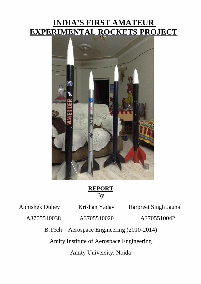
INDIA’S FIRST AMATEUR
EXPERIMENTAL ROCKETS PROJECT
REPORT
By
Abhishek Dubey Krishan Yadav Harpreet Singh Jauhal
A3705510038 A3705510020 A3705510042
B.Tech – Aerospace Engineering (2010-2014)
Amity Institute of Aerospace Engineering
Amity University, Noida
ACKNOWLEDGEMENTS
A project of this scale can never be concluded without moral, inspirational support as
well as help from people around us. We would like to express our gratitude to our
guide, Gp. Cpt. R.C.Garg and our head of institute, Dr. Sanjay Singh, for
understanding our potential and approving our project, and helping us throughout in
every possible way. It is because of their endless support that we were able to keep our
project on schedule at every phase.
We also thank the Head of Dept. of Mechanical Engineering for allowing us to
use the machines in for fabrication of the project equipment. We thank the Lab.
assistants Mr. Mahesh, Mr. Ramji, Mr. Amit and other lab supervisors for their
support.
The project required permissions from Govt. of India authorities. For smooth
process of all the permission procedures, we thank wholeheartedly, Mr. T.R Thomas,
Chief Controller of Explosives and Dr. Sudarshan Kamal, Jt. Chief Controller of
Explosives, Petroleum and Explosives Safety Organisation, for considering our
project and making the procedures easy and fast considering our time limits. We also
thanks Mr. J.S.Rawat, Jt. Director General, and Mr. A.K.Bhardawaj, Director of
operations, and other officials at Directorate General of Civil Aviation, to grant us
the launch permission for the rockets.
We thank Mr. Rahul and Mr. Arvind from the Amity Institute of Pharmacy,
for they provided us with necessary equipment without any objection for our
convenience.
We are extremely thankful to Prof.R.K.Verma, Mr. R.KChauhan, and our friends,
for their support and help they have extended.
We thank local hardware shop and machine shop owners for lending us a helping hand
for fabrication of the rocket parts

Last but not the least; we thank our families, for supporting us both morally, and
monetarily, without any second thoughts and bearing with us through numerous tiring
days and sleepless nights.
The Project Team.
CONTENTS
1. Introduction
2. The Propellant
- Physical and Chemical Properties - Performance Characteristics - Casting and Curing methods
3. Strand Burner
- Strand Burner Design - Operating Procedure
4. Ignition System
- Requirements - Circuit Design - Fabrication
5. The Rockets
- Concorde - Waverider - Skylon - Indra - Curiosity
6. Concorde
- Solid Rocket Motor design and performance - Rocket Body Design and Fabrication - Recovery system and Parachute - CFD Simulations
7. Static Test Stand
- Operating Principle - Design - Fabrication - Pressure to Thrust Conversion Formula
8. Tests and Analysis
- Motor Static Tests - Parachute Drop Tests - Recovery System Tests - Ignition System Tests - Rocket Stability Tests
9. Launch
- Launch Site - Launch Pad and Lugs - Range Safety - Post Launch Analyisis
10. Legal Permissions and Safety Requirements
- Rules - Permissions - Safety Precautions
11. Conclusion
12. Appendices
1. INTRODUCTION
Amateur Rockets are rare in India. With almost no infrastructure for students to make rockets, to
lack of material availability, and no clear dedication laws and rules, it is a very tough task to take an
experimental amateur rocket to the launch pad from the design table. However, for the purpose of
final year project, something major was to be done. As a result, we three students decided to design,
fabricate, test, and launch some experimental rockets for the sake of practical knowledge with some
real hands on work. The project included many aspects from design on papers to intensive machine
work at workshops and late night troubleshooting of various systems. A mammoth amount of hours
were dedicated to make the project as much successful as we can. The learning outcomes were even
larger, with revision of even the minutest concepts to learning of some never before studied subjects.
This project was the first of its kind in India, with first ever amateur rockets designed
completely by students, with limited resources and under the rules of the government. Safety was
one of the most important aspect of this project, as it included handling of propellants (considered as
explosive as per Explosives Act of India). The whole project was completed in such a way so as to
minimize the propellant handling duration for decreasing the probability of any mishap. Not even a
single incident occurred throughout the course of the project which could cause loss/damage to life
or property. One of the goals of this project was to establish and continue the safety record of
Amateur/Model Rocketry throughout the world.
A total of FIVE Rockets were designed and fabricated over duration of 1 years, with 4
rockets designed in just 2 months while the first one in 5-6 months. These are CONCORDE,
WAVERIDER, SKYLON, CURIOSITY, and INDRA. However, CONCORDE and CURIOSITY
achieved partially successful flights, while the other three didn’t. The causes of partial success have
been mentioned and discussed thoroughly in the Post Launch Analysis section of the report.
The report contains the complete design features of the largest rocket (by length) CONCORDE and
its CFD simulations along with static tests of its rocket motor.
The rockets CONCORDE, SKYLON, and WAVERIDER were more or less same in design. The
only difference between them was the total size, and motor impulse. Similarly, CURIOSITY, and INDRA were similar to each other, with the difference being in the body diameter, length and motor
impulse. The difference between the two groups of rockets was the Recovery System used in them,
with the former using a ‘servo actuated parachute ejector’, while the latter used a ‘black powder
assisted piston assembly.
The propellant used for the rockets, called the Rocket Candy propellant throughout the world,
has been described in detail in the Propellant Details section of the report. The behavior of the
propellant was first studied by experimentation using strands. This data was compared to literature
and negligible or insignificant variations were found. The motors were then designed using the
literature data, and the graphs were obtained for the performance of the motors.
The static tests of rocket motors were the most important part of the project. However, due to
probable high costs of an advanced data acquisition test stand and non-availability of required
sensors/transducers limited the test to measure only the maximum thrust of the motors. Also, other
objectives of the tests like burn time, inhibitor and insulator performance and other visual inspections
were successfully achieved. The details are mentioned in the Test and Analysis section of this
report.
Another objective of the project was to, recover the launched rockets intact. For this, a
recovery system was required. For this, independent parachutes and parachute ejection systems were
designed and fabricated. In all, two designs of ejection systems were fabricated. The details of these
systems are mentioned in the sections of the rockets in which they were used.
A rocket uses a propellant which is to be casted at a facility and needs airspace for launch and a vast
open field as the launch site. All these procedures require clearance from respective authorities under
specific rules. These have been detailed in the Legal Permissions and Safety Requirements section
of the report.
The report includes all details of the project and can be used to estimate the requirements for
other such projects in future. It has been produced for simple and easy understanding of the reader.
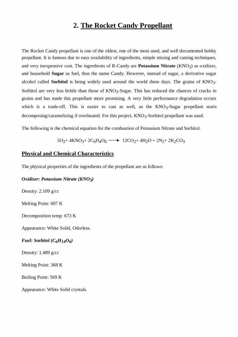
2. The Rocket Candy Propellant
The Rocket Candy propellant is one of the oldest, one of the most used, and well documented hobby
propellant. It is famous due to easy availability of ingredients, simple mixing and casting techniques,
and very inexpensive cost. The ingredients of R-Candy are Potassium Nitrate (KNO3) as oxidizer,
and household Sugar as fuel, thus the name Candy. However, instead of sugar, a derivative sugar
alcohol called Sorbitol is being widely used around the world these days. The grains of KNO3-
Sorbitol are very less brittle than those of KNO3-Sugar. This has reduced the chances of cracks in
grains and has made this propellant more promising. A very little performance degradation occurs
which is a trade-off. This is easier to cast as well, as the KNO3-Sugar propellant starts
decomposing/caramelizing if overheated. For this project, KNO3-Sorbitol propellant was used.
The following is the chemical equation for the combustion of Potassium Nitrate and Sorbitol.
5O2+ 4KNO3+ 2C6H4O6 12CO2+ 4H2O + 2N2+ 2K2CO3
Physical and Chemical Characteristics
The physical properties of the ingredients of the propellant are as follows:
Oxidiser: Potassium Nitrate (KNO3)
Density: 2.109 g/cc
Melting Point: 607 K
Decomposition temp: 673 K
Appearance: White Solid, Odorless.
Fuel: Sorbitol (C6H14O6)
Density: 1.489 g/cc
Melting Point: 368 K
Boiling Point: 569 K
Appearance: White Solid crystals.
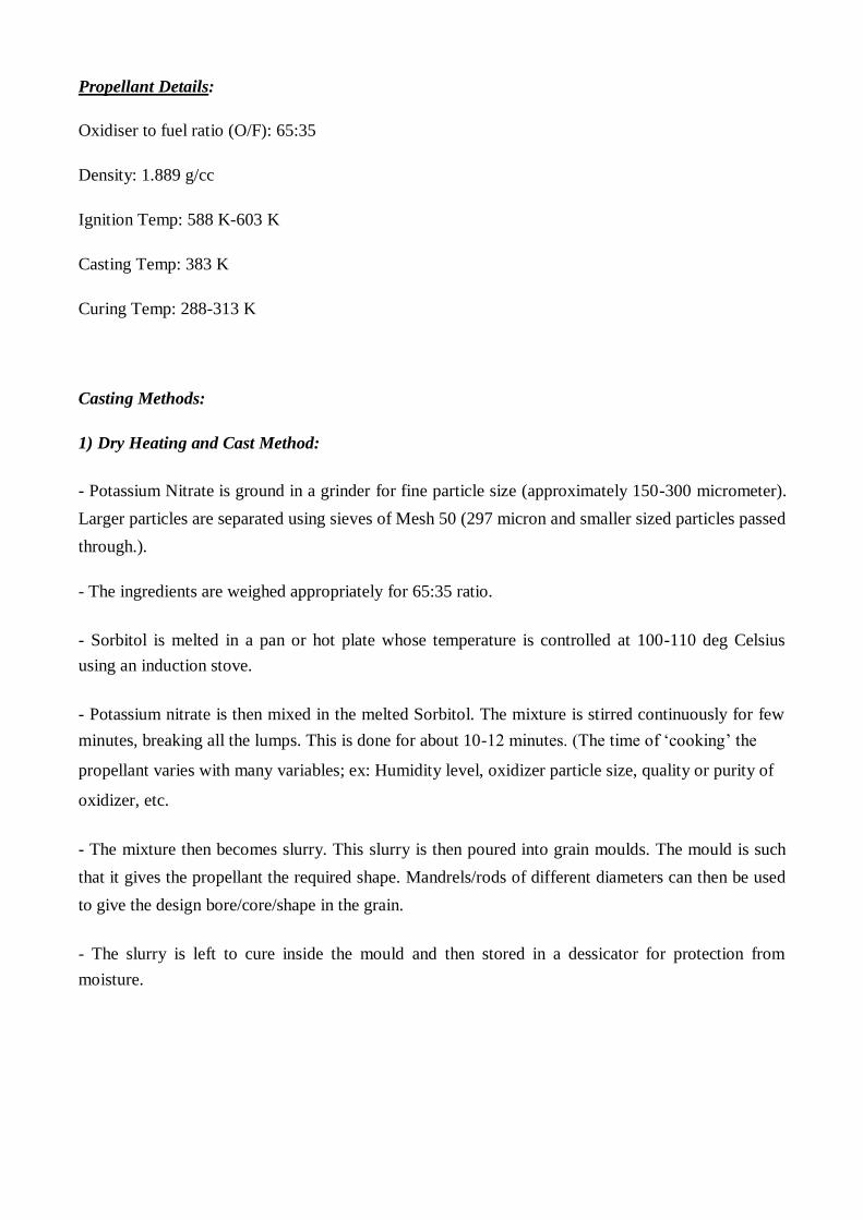
Propellant Details:
Oxidiser to fuel ratio (O/F): 65:35
Density: 1.889 g/cc
Ignition Temp: 588 K-603 K
Casting Temp: 383 K
Curing Temp: 288-313 K
Casting Methods:
1) Dry Heating and Cast Method:
- Potassium Nitrate is ground in a grinder for fine particle size (approximately 150-300 micrometer).
Larger particles are separated using sieves of Mesh 50 (297 micron and smaller sized particles passed
through.).
- The ingredients are weighed appropriately for 65:35 ratio.
- Sorbitol is melted in a pan or hot plate whose temperature is controlled at 100-110 deg Celsius
using an induction stove.
- Potassium nitrate is then mixed in the melted Sorbitol. The mixture is stirred continuously for few
minutes, breaking all the lumps. This is done for about 10-12 minutes. (The time of ‘cooking’ the propellant varies with many variables; ex: Humidity level, oxidizer particle size, quality or purity of oxidizer, etc.
- The mixture then becomes slurry. This slurry is then poured into grain moulds. The mould is such
that it gives the propellant the required shape. Mandrels/rods of different diameters can then be used
to give the design bore/core/shape in the grain.
- The slurry is left to cure inside the mould and then stored in a dessicator for protection from
moisture.
2) Recrystallization Method:
- The constituent chemicals are weighed according to the propellant Oxidizer to Fuel (O/F) ratio.
- Both are then dissolved in distilled water of volume equal in magnitude to the oxidizer mass; ex: If
the propellant batch to be made is 100gm, i.e., Oxidizer=65g, Fuel= 35g, then both are dissolved in
65ml of water.
- The whole solution is heated at 110 deg Celsius, and stirred continuously.
- The water boils off, leaving behind the propellant slurry, which can either be stored for future use
or casted in required grain shape by putting it into the grain mould.
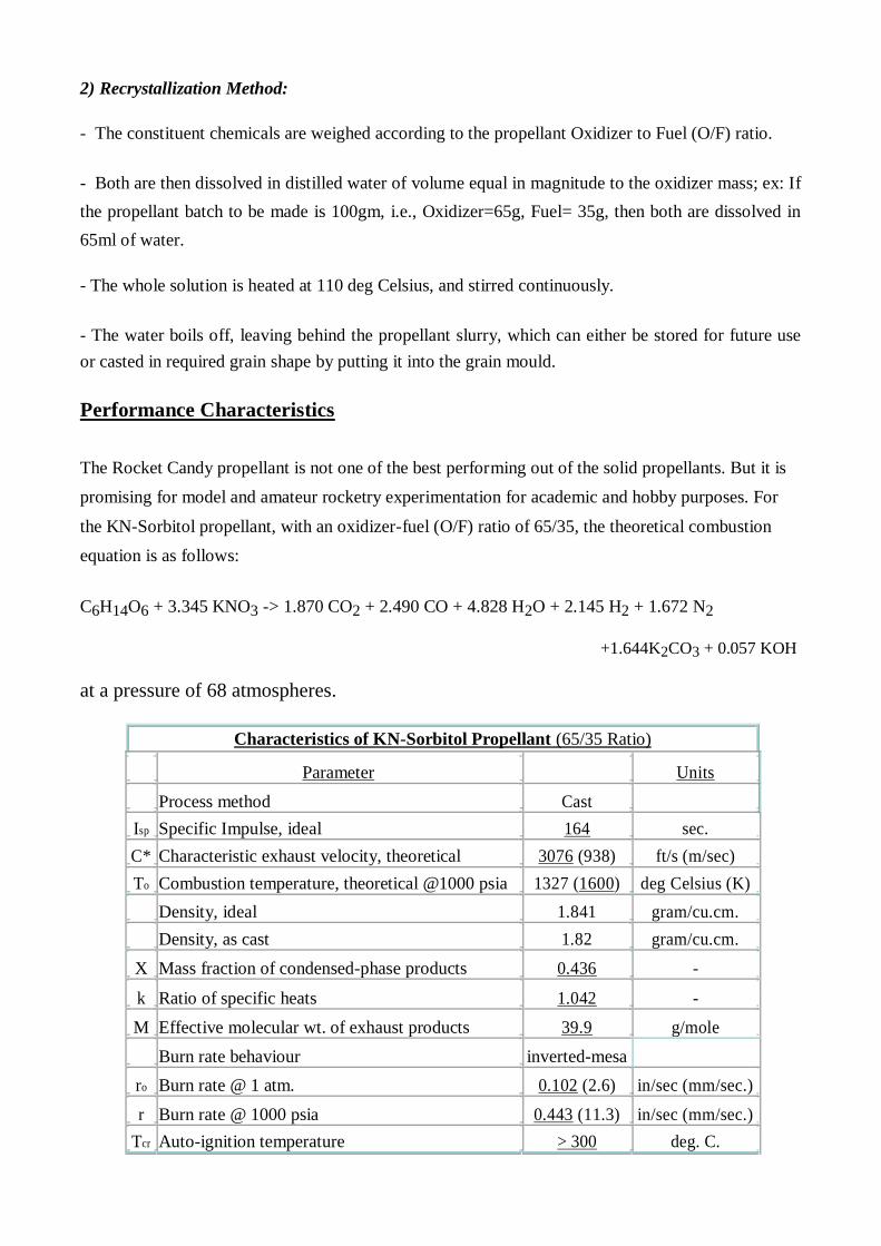
Performance Characteristics
The Rocket Candy propellant is not one of the best performing out of the solid propellants. But it is
promising for model and amateur rocketry experimentation for academic and hobby purposes. For
the KN-Sorbitol propellant, with an oxidizer-fuel (O/F) ratio of 65/35, the theoretical combustion
equation is as follows:
C6H14O6 + 3.345 KNO3 -> 1.870 CO2 + 2.490 CO + 4.828 H2O + 2.145 H2 + 1.672 N2
+1.644K2CO3 + 0.057 KOH
at a pressure of 68 atmospheres.
Characteristics of KN-Sorbitol Propellant (65/35 Ratio)
Parameter Units
Process method Cast
Isp Specific Impulse, ideal 164 sec.
C* Characteristic exhaust velocity, theoretical 3076 (938) ft/s (m/sec)
To Combustion temperature, theoretical @1000 psia 1327 (1600) deg Celsius (K)
Density, ideal 1.841 gram/cu.cm.
Density, as cast 1.82 gram/cu.cm.
X Mass fraction of condensed-phase products 0.436 -
k Ratio of specific heats 1.042 -
M Effective molecular wt. of exhaust products 39.9 g/mole
Burn rate behaviour inverted-mesa
ro Burn rate @ 1 atm. 0.102 (2.6) in/sec (mm/sec.)
r Burn rate @ 1000 psia 0.443 (11.3) in/sec (mm/sec.)
Tcr Auto-ignition temperature > 300 deg. C.
Safety and Precautions:
The rocket Candy propellant is a widely used hobby propellant. With certain basic safety equipment
and measures, it is a very safe. It is used at high school level as an academic aid for giving students
some hands on experience on rocketry. However, negligent behavior might cause danger or serious
burn injuries. Motors made with R candy must be tested in open fields with no life and property
nearby or at established laboratories only. This propellant has a very good track record as far as
safety is concerned. Certain precautions must be observed, like:
- Propellant ingredients must not be kept mixed in containers until and unless casting is to be
done.
- Casting should be done with small batches (Preferably not more than 200 gram at one time
for amateur purposes)
- Casting/Cooking must be done on a flameless heat source.
- Casting must be done in an open area/field/established laboratory away from ignition sources,
flammable substances.
- Fire Extinguishers must be kept while casting and near storage points to stop propagation of
fire in case of accidental ignition.
- Casting must be done strictly on a temperature controlled device/ heat source. Temperature
must be monitored always.
- Stirring must be done while cooking so as to prevent any local hotspots in the cast pan to
avoid ignition.
- First Aid equipments/medication must be readily available.
- Propellant must not be stored in metallic containers.
- Safety equipments must be worn by operator.
- Number of people performing casting operation must be kept to the possible minimum.
- In case casting is to be done in a confined place, evacuation routes must be clear and well
rehearsed.
- Storage must be done at a place away from any flammable substance, ignition source. It
should be kept in a secure place away from the reach of people who may misuse it.
- Efforts must be made to minimize the storage period as much as possible and use the
propellant early. Casting should be done only in a period nearing the use of propellant and
not well in advance.
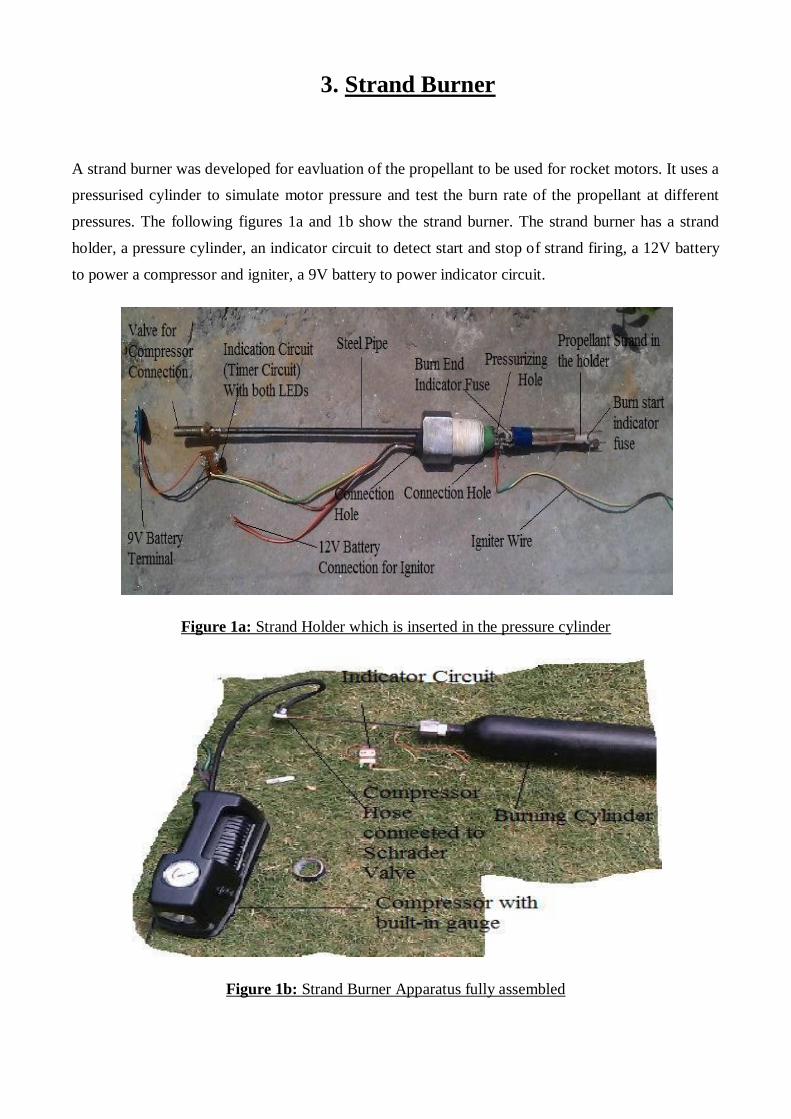
3. Strand Burner
A strand burner was developed for eavluation of the propellant to be used for rocket motors. It uses a
pressurised cylinder to simulate motor pressure and test the burn rate of the propellant at different
pressures. The following figures 1a and 1b show the strand burner. The strand burner has a strand
holder, a pressure cylinder, an indicator circuit to detect start and stop of strand firing, a 12V battery
to power a compressor and igniter, a 9V battery to power indicator circuit.
Figure 1a: Strand Holder which is inserted in the pressure cylinder
Figure 1b: Strand Burner Apparatus fully assembled
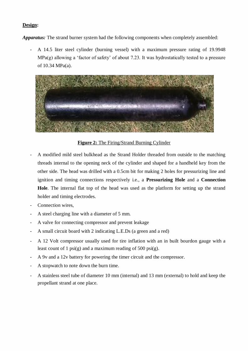
Design:
Apparatus: The strand burner system had the following components when completely assembled:
- A 14.5 liter steel cylinder (burning vessel) with a maximum pressure rating of 19.9948
MPa(g) allowing a ‘factor of safety’ of about 7.23. It was hydrostatically tested to a pressure
of 10.34 MPa(a).
Figure 2: The Firing/Strand Burning Cylinder
- A modified mild steel bulkhead as the Strand Holder threaded from outside to the matching
threads internal to the opening neck of the cylinder and shaped for a handheld key from the
other side. The head was drilled with a 0.5cm bit for making 2 holes for pressurizing line and
ignition and timing connections respectively i.e., a Pressurizing Hole and a Connection
Hole. The internal flat top of the head was used as the platform for setting up the strand
holder and timing electrodes.
- Connection wires,
- A steel charging line with a diameter of 5 mm.
- A valve for connecting compressor and prevent leakage
- A small circuit board with 2 indicating L.E.Ds (a green and a red)
- A 12 Volt compressor usually used for tire inflation with an in built bourdon gauge with a
least count of 1 psi(g) and a maximum reading of 500 psi(g).
- A 9v and a 12v battery for powering the timer circuit and the compressor.
- A stopwatch to note down the burn time.
- A stainless steel tube of diameter 10 mm (internal) and 13 mm (external) to hold and keep the
propellant strand at one place.
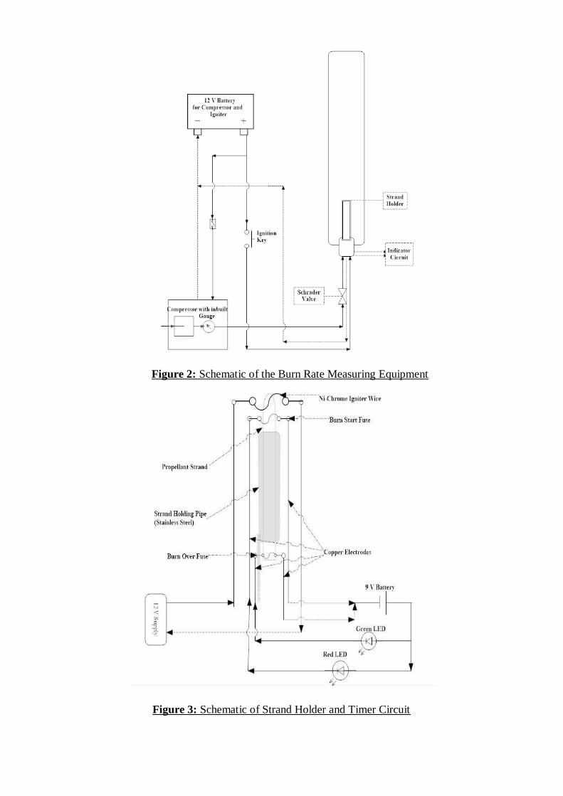
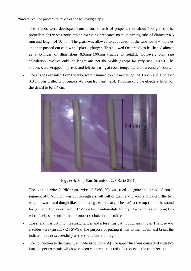
Figure 2: Schematic of the Burn Rate Measuring Equipment Figure 3: Schematic of Strand Holder and Timer Circuit
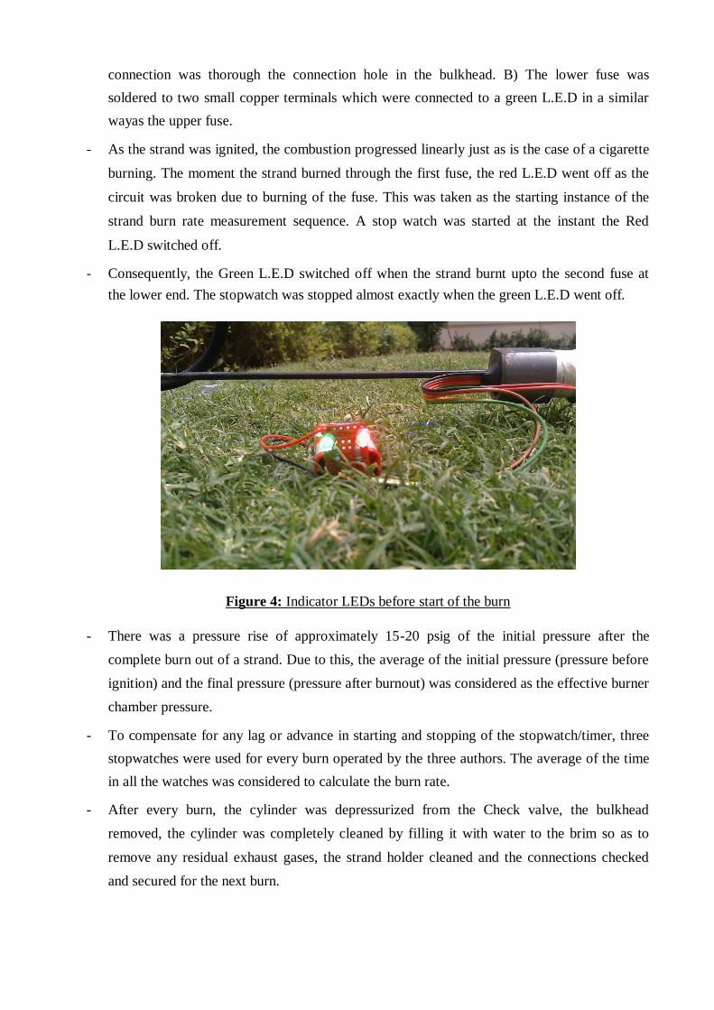
Procedure: The procedure involves the following steps:
- The strands were developed from a small batch of propellant of about 100 grams. The
propellant slurry was pour into an extruding preheated metallic casting tube of diameter 8.5
mm and length of 10 mm. The grain was allowed to cool down in the tube for few minutes
and then pushed out of it with a plastic plunger. This allowed the strands to be shaped almost
as a cylinder of dimensions 8.5mm×100mm (radius to height). However, burn rate
calculation involves only the length and not the width (except for very small sizes). The
strands were wrapped in plastic and left for curing at room temperature for around 24 hours.
- The strands extruded from the tube were trimmed to an exact length of 9.4 cm and 1 hole of
0.3 cm was drilled with centers at0.5 cm from each end. Thus, making the effective length of
the strand to be 8.4 cm.
Figure 4: Propellant Strands of O/F Ratio 65/35
- The ignition wire (a NiChrome wire of SWG 30) was used to ignite the strand. A small
segment of 0.3-0.5 cm was put through a small ball of grain and placed and pasted (the ball
was still warm and dough-like, eliminating need for any adhesive) at the top end of the strand
for ignition. The source was a 12V Lead-acid automobile battery. It was connected using two
wires freely standing from the connection hole in the bulkhead.
- The strand was put into the strand holder and a fuse was put through each hole. The fuse was
a solder wire (tin alloy-24 SWG). The purpose of putting it was to melt down and break the
indicator circuit successfully as the strand burnt through it.
- The connection to the fuses was made as follows: A) The upper fuse was connected with two
long copper terminals which were then connected to a red L.E.D outside the chamber. The
connection was thorough the connection hole in the bulkhead. B) The lower fuse was
soldered to two small copper terminals which were connected to a green L.E.D in a similar
wayas the upper fuse. - As the strand was ignited, the combustion progressed linearly just as is the case of a cigarette
burning. The moment the strand burned through the first fuse, the red L.E.D went off as the
circuit was broken due to burning of the fuse. This was taken as the starting instance of the
strand burn rate measurement sequence. A stop watch was started at the instant the Red
L.E.D switched off. - Consequently, the Green L.E.D switched off when the strand burnt upto the second fuse at
the lower end. The stopwatch was stopped almost exactly when the green L.E.D went off.
Figure 4: Indicator LEDs before start of the burn
- There was a pressure rise of approximately 15-20 psig of the initial pressure after the
complete burn out of a strand. Due to this, the average of the initial pressure (pressure before
ignition) and the final pressure (pressure after burnout) was considered as the effective burner
chamber pressure. - To compensate for any lag or advance in starting and stopping of the stopwatch/timer, three
stopwatches were used for every burn operated by the three authors. The average of the time
in all the watches was considered to calculate the burn rate. - After every burn, the cylinder was depressurized from the Check valve, the bulkhead
removed, the cylinder was completely cleaned by filling it with water to the brim so as to
remove any residual exhaust gases, the strand holder cleaned and the connections checked
and secured for the next burn.
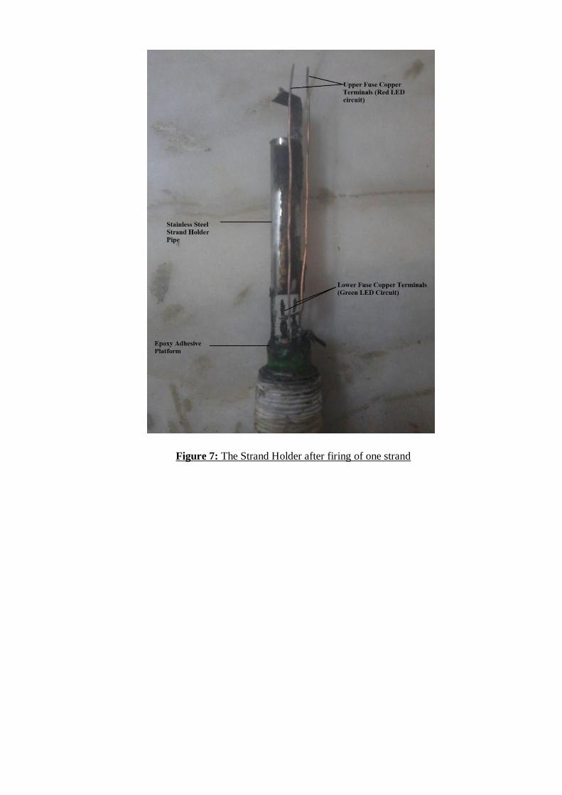
Figure 7: The Strand Holder after firing of one strand
4. Ignition System
Requirements and characteristics of an Ignition System
The ignition system of a rocket must satisfy the following requirements:
- Remote Controlled or Distant ignition system: The system must be able to ignite the motor
from a distance of at least 100m. It may be wireless or wired.
- The ignition system must have a timer so as to initiate the ignition sequence with a
countdown.
- The ignition sequence must be in control of the launch/engine fire operator.
- The system must have an abort/cancel key which can break the ignition/fire sequence in case
of an emergency or a situation where firing is not recommended.
- The system must be reliable and must have a success rate of at least 90%.
- The system must have low power consumption and less impedance.
- It must be portable or one that can be fitted onboard the rocket.
- The system must have a safety system/Safety key that can be operated only by the operator.
This key/switch must be armed only during the countdown to avoid any accidental ignition.
- The igniter fuse or charge must fire only after certain threshold energy is reached inside the
firing chain. This ensures any accidental ignition command or static charge doesn’t ignite the
charge and the motor. Also, this increases the reliability by ensuring that the igniter, when
ignited, will fire with the maximum or design energy. Thus, reducing chances of ‘No Joy’ (A
situation where igniter charge has fired but motor ignition did not occur, or failed ignition).
- The overall cost of the system must be as low as possible.
- The maintenance or diagnosis of defects must be easy for longevity of the system.
- The ignition must be instantaneous. The ignition charge must be in optimum amount so as to
make the rocket motor able to reach the initial pressure at which combustion can be
sustained.
- The ignition charge combination (explosive train, if any) must be selected in such a way so as
to make the ignition reliable, less energy consuming, and inexpensive.
Ignition System Major Components:
1) A Circuit: The circuit consists of a power source and a timer. It contains a capacitor which is
charged to its capacitance and this provides the instantaneous amount of energy required to
ignite the charge in a very short time. The circuit has the ignition key, safety arm key, and/or
an abort key.
2) The Ignition Charge/Pyrogen: The charge is the explosive material which ignites readily by
the melting/red hot fuse. This charge then ignites a small amount of propellant which is place
in contact with the charge in a small canister/pellet. The hot high speed gases so produced
ignite the whole exposed surface of the propellant grain
Circuit Design The requirements of the ignition system were considered and after few iterative designs, a circuit
design was achieved. This system was name ‘Carbon Resistor based Capacitor Discharge
Ignition (C.R.CDi) system. The system was designed keeping in mind the size, cost, and reliability.
The circuit design is shown in the following figure. This circuit was designed to unify the ignition
system and a recovery system triggering mechanism for one of the rockets. It was used in CONCORDE and WAVERIDER. Both the rockets were designed to have onboard automatic head-
on ignition system. The other three rockets, SKYLON, INDRA, and CURIOSITY had ground based
ignition with igniters put into motors through nozzles.
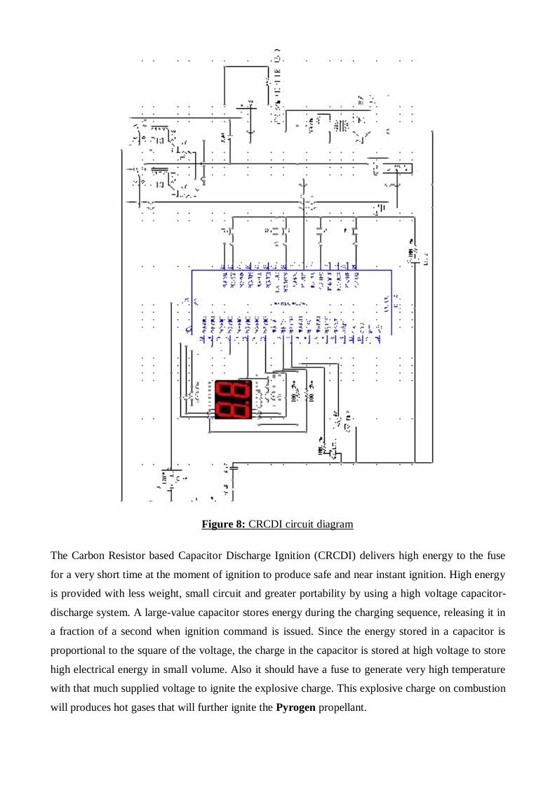
Figure 8: CRCDI circuit diagram
The Carbon Resistor based Capacitor Discharge Ignition (CRCDI) delivers high energy to the fuse
for a very short time at the moment of ignition to produce safe and near instant ignition. High energy
is provided with less weight, small circuit and greater portability by using a high voltage capacitor-
discharge system. A large-value capacitor stores energy during the charging sequence, releasing it in
a fraction of a second when ignition command is issued. Since the energy stored in a capacitor is
proportional to the square of the voltage, the charge in the capacitor is stored at high voltage to store
high electrical energy in small volume. Also it should have a fuse to generate very high temperature
with that much supplied voltage to ignite the explosive charge. This explosive charge on combustion
will produces hot gases that will further ignite the Pyrogen propellant.
The heart of the resistor igniter is a quarter-watt, carbon film 5% tolerance resistor. ¼ watt carbon
resistors are very efficient as fuse in the capacitor discharge ignition system. The energy supplied by
the capacitor to the ¼ watt resistor must be more than 10 joules to burn the resistor. A 330 µF
capacitor charged at 250 V has 10.31 joules of electrical energy. On discharging this much energy to
the carbon resistor the initial power supplied to the resistor is 190 watt which is much higher than its
rated power of 0.25 watt. The average power supplied to the resistor in the time duration of capacitor
discharge is 50 watt. This will result in high heat flux per unit area, overheating of the resistor
instantly to produce hot flame to ignite the explosive charge. The value of the carbon resistor used as
fuse is 330Ω. The resistor can be replaced by a NiChrome wire as well.
The main advantages of the resistor initiator, in addition to reliability, are:
1. The ability to convert substantial quantities of electrical energy into heat within a very
small space, due to the concentration of high resistance into a small area.
2. The ability to transfer substantial quantities of energy over long distances with high
efficiency, due to the high resistance of the resistor initiator. This allows the rocket ignition
to be commanded through a wire more than 1 km long.
3. Resistant to an accidental electrostatic discharge from a human body. A human body
carrying a static charge of 30,000 volts has only about 0.045 joule of stored electrical
energy(less than 1/200th
of the energy needed to burn the carbon film resistor).
4. High degree of safety: The capacitor is initially uncharged and need about a minute to
charge up to 250V. This makes it possible to charge the capacitor during rocket
countdown eliminating chances of any accidental ignition before launch.
Fabrication
The circuit was fabricated using the below parts. It was fabricated on a Pref Board. A Printed Circuit
board was avoided due to costs. Also, a hand soldered circuit had many learning outcomes and was
fun to do.
The Pyrogen was made using Diwali cracker powder, match powder, and the propellant. Match Powder ignited readily. This assisted in black powder ignition which then ignited the pyrogen grain.
The bulkhead was fabricated on Lathe Machine by the students in college Laboratory as well as at a
local workshop. It was machined out of a Mild Steel Bar stock. The same material with which the
Nozzles were made.
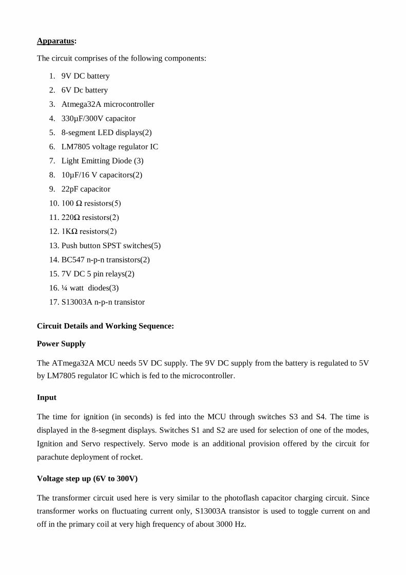
Apparatus: The circuit comprises of the following components:
1. 9V DC battery
2. 6V Dc battery
3. Atmega32A microcontroller
4. 330µF/300V capacitor
5. 8-segment LED displays(2)
6. LM7805 voltage regulator IC
7. Light Emitting Diode (3)
8. 10µF/16 V capacitors(2)
9. 22pF capacitor
10. 100 Ω resistors(5)
11. 220Ω resistors(2)
12. 1KΩ resistors(2)
13. Push button SPST switches(5)
14. BC547 n-p-n transistors(2)
15. 7V DC 5 pin relays(2)
16. ¼ watt diodes(3)
17. S13003A n-p-n transistor Circuit Details and Working Sequence:
Power Supply
The ATmega32A MCU needs 5V DC supply. The 9V DC supply from the battery is regulated to 5V
by LM7805 regulator IC which is fed to the microcontroller.
Input
The time for ignition (in seconds) is fed into the MCU through switches S3 and S4. The time is
displayed in the 8-segment displays. Switches S1 and S2 are used for selection of one of the modes,
Ignition and Servo respectively. Servo mode is an additional provision offered by the circuit for
parachute deployment of rocket.
Voltage step up (6V to 300V)
The transformer circuit used here is very similar to the photoflash capacitor charging circuit. Since
transformer works on fluctuating current only, S13003A transistor is used to toggle current on and
off in the primary coil at very high frequency of about 3000 Hz.
High voltage storage
The high 250V DC generated from the transformer is stored in the 330µF/300V capacitor up until
the ignition countdown reaches 0. The time constant of the circuit is such that capacitor charges
maximum up to 250V (below the maximum rated voltage of 300V).
Ignition
The ignition is done by discharging the energy stored in capacitor through a 220Ω/330Ω resistor that
acts as a fuse. The relay R1 is used to connect the high voltage capacitor with the 220Ω. R2 is
switched on by the BC547 transistor at the instant of ignition. The additional relay R1 provides the
6V DC supply to the transformer circuit while the capacitor is being charged (after ignition the relay
R1 is used to power the 6V DC to the servo motor).
The resulting hot temperature of the resistor ignites the explosive charge.
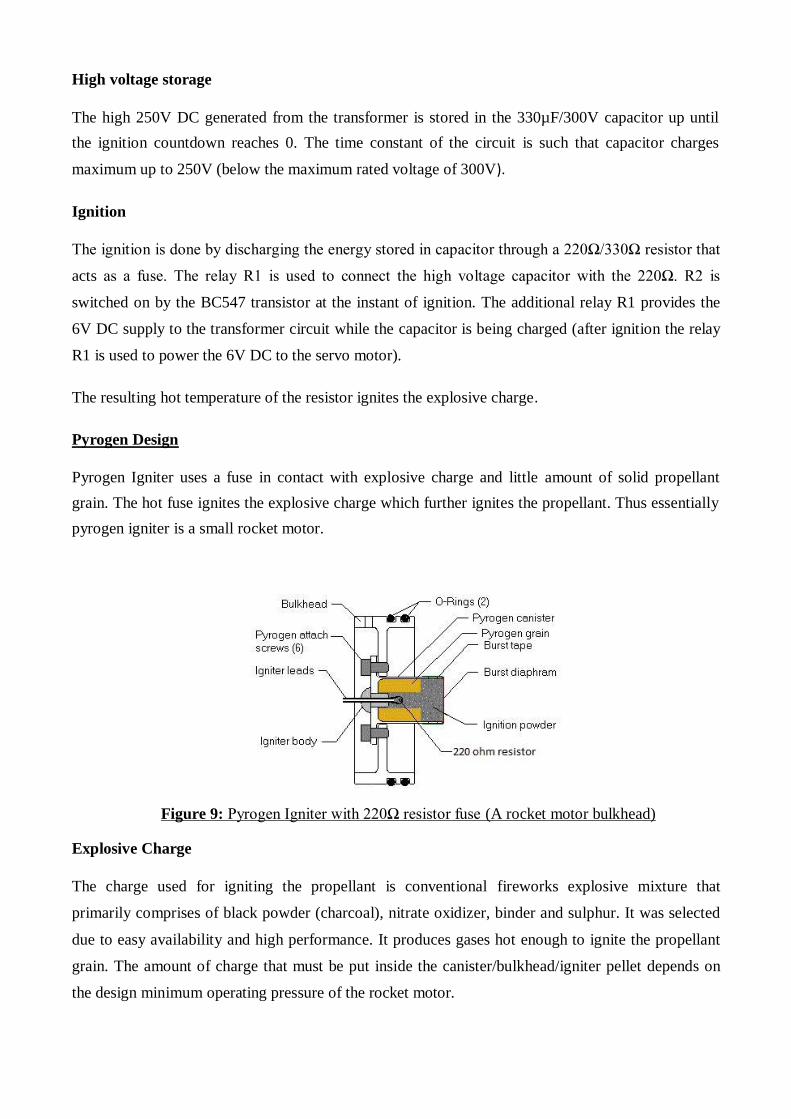
Pyrogen Design
Pyrogen Igniter uses a fuse in contact with explosive charge and little amount of solid propellant
grain. The hot fuse ignites the explosive charge which further ignites the propellant. Thus essentially
pyrogen igniter is a small rocket motor.
Figure 9: Pyrogen Igniter with 220Ω resistor fuse (A rocket motor bulkhead) Explosive Charge
The charge used for igniting the propellant is conventional fireworks explosive mixture that
primarily comprises of black powder (charcoal), nitrate oxidizer, binder and sulphur. It was selected
due to easy availability and high performance. It produces gases hot enough to ignite the propellant
grain. The amount of charge that must be put inside the canister/bulkhead/igniter pellet depends on
the design minimum operating pressure of the rocket motor.
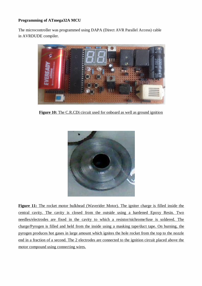
Programming of ATmega32A MCU
The microcontroller was programmed using DAPA (Direct AVR Parallel Access) cable
in AVRDUDE compiler.
Figure 10: The C.R.CDi circuit used for onboard as well as ground ignition Figure 11: The rocket motor bulkhead (Waverider Motor). The igniter charge is filled inside the
central cavity. The cavity is closed from the outside using a hardened Epoxy Resin. Two
needles/electrodes are fixed in the cavity to which a resistor/nichrome/fuse is soldered. The
charge/Pyrogen is filled and held from the inside using a masking tape/duct tape. On burning, the
pyrogen produces hot gases in large amount which ignites the hole rocket from the top to the nozzle
end in a fraction of a second. The 2 electrodes are connected to the ignition circuit placed above the
motor compound using connecting wires.
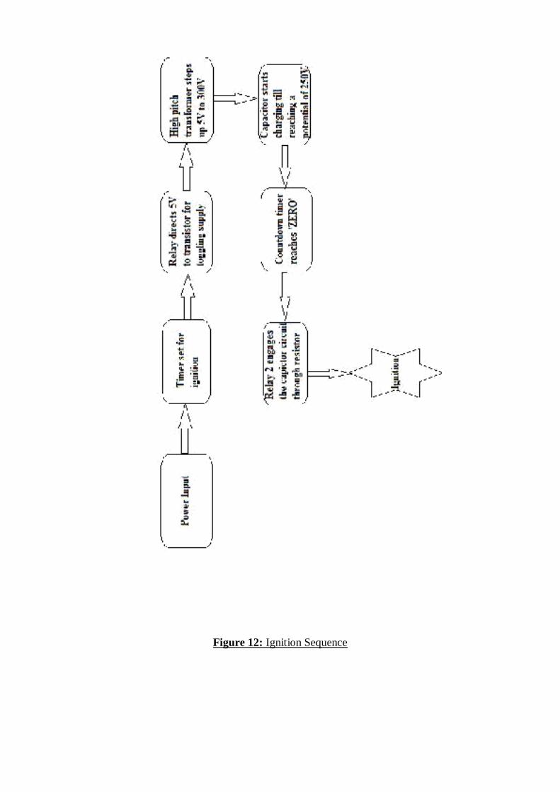
Figure 12: Ignition Sequence
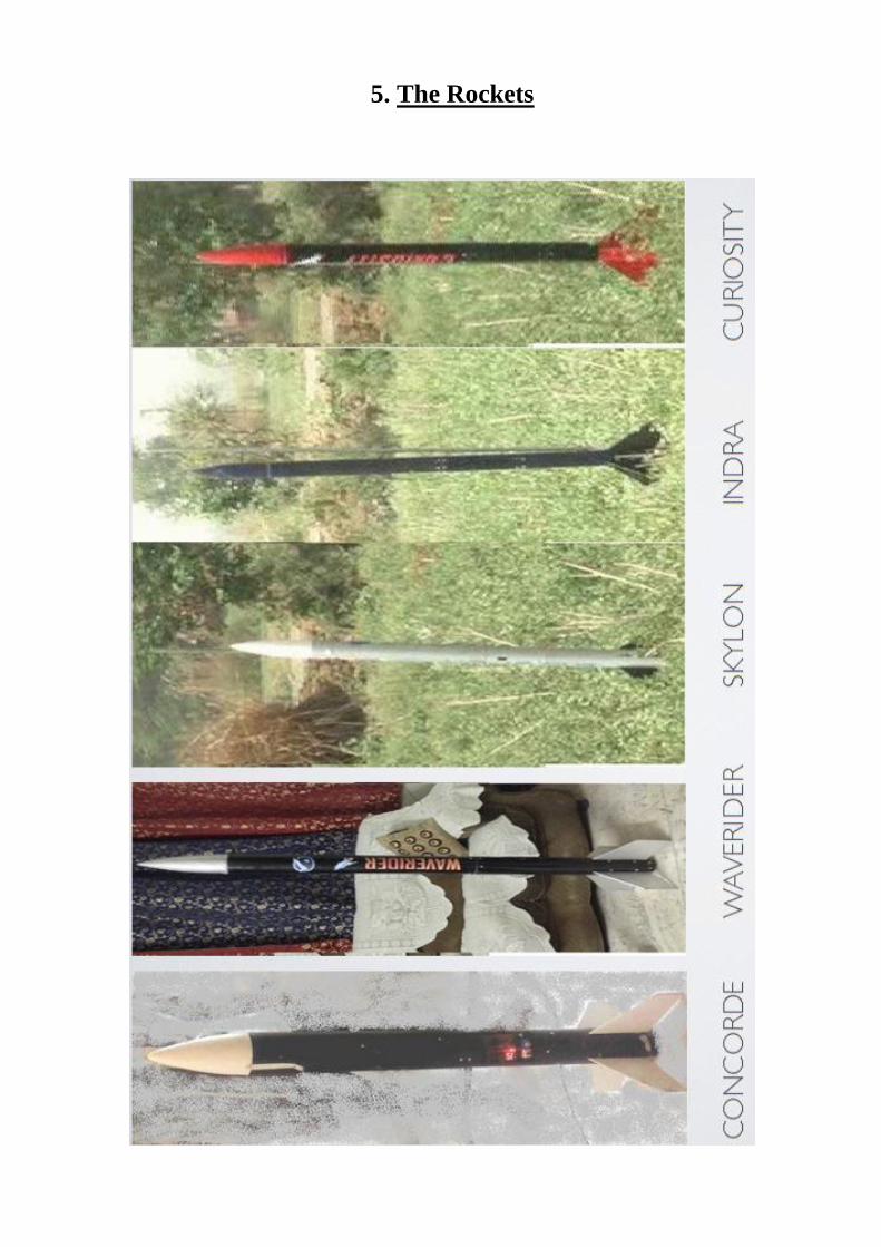
5. The Rockets
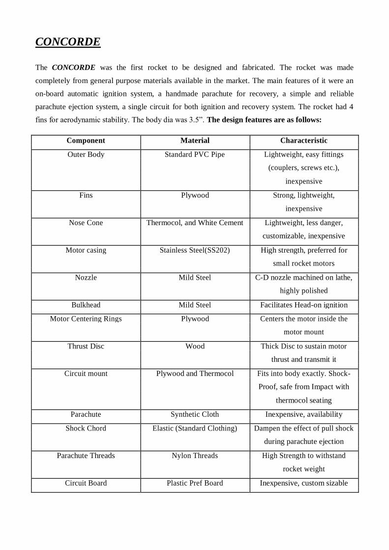
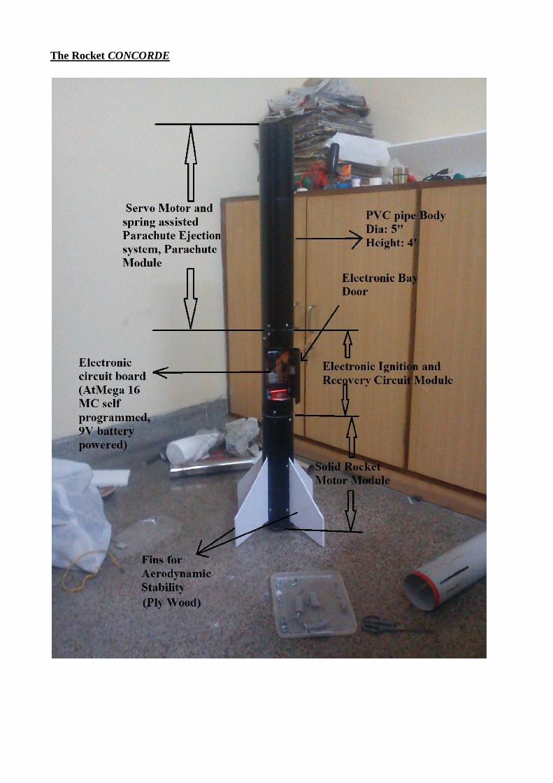
CONCORDE The CONCORDE was the first rocket to be designed and fabricated. The rocket was made
completely from general purpose materials available in the market. The main features of it were an
on-board automatic ignition system, a handmade parachute for recovery, a simple and reliable
parachute ejection system, a single circuit for both ignition and recovery system. The rocket had 4
fins for aerodynamic stability. The body dia was 3.5”. The design features are as follows:
Component Material Characteristic
Outer Body Standard PVC Pipe Lightweight, easy fittings
(couplers, screws etc.),
inexpensive
Fins Plywood Strong, lightweight,
inexpensive
Nose Cone Thermocol, and White Cement Lightweight, less danger,
customizable, inexpensive
Motor casing Stainless Steel(SS202) High strength, preferred for
small rocket motors
Nozzle Mild Steel C-D nozzle machined on lathe,
highly polished
Bulkhead Mild Steel Facilitates Head-on ignition
Motor Centering Rings Plywood Centers the motor inside the
motor mount
Thrust Disc Wood Thick Disc to sustain motor
thrust and transmit it
Circuit mount Plywood and Thermocol Fits into body exactly. Shock-
Proof, safe from Impact with
thermocol seating
Parachute Synthetic Cloth Inexpensive, availability
Shock Chord Elastic (Standard Clothing) Dampen the effect of pull shock
during parachute ejection
Parachute Threads Nylon Threads High Strength to withstand
rocket weight
Circuit Board Plastic Pref Board Inexpensive, custom sizable
CONCORDE’s Objectives: This rocket was the first among the five to be completed. The rocket was made with a purpose of
proving the flight performance of the motor, the ignition system, the reliability of recovery system,
the performance and strength of parachute, the flight performance of a rocket regarding stability,
altitude achieved etc. The concrete objectives were:
- To develop a modular design for amateur rockets
- To test a solid rocket motor with a robust design for sounding rockets by college students.
- To test an ignition system with reliable and instantaneous ignition of rocket motor with head-
on ignition
- To test the performance and reliability of an electronic circuit under large gravitational loads
of about 16g - 20 g.
- To analyse the structural status of a rocket body and its components recovered after a high
acceleration flight. To analyse any structural deformity or damage caused due to aerodynamic
loads
- To achieve a stable vertical flight and establish the stability criterion further.
- To test a unique mechanical parachute ejection mechanism.
- To recover the rocket and establish its reusability as a sounding rocket for students.
- To achieve an altitude of more than 800 metres using hobby propellant (Rocket Candy).
The CONCORDE had a modular design unlike model rockets which have a single body. This was
decided so as to felicitate easy dissembling of the rocket for easy transport. The whole rocket was
fabricated in such a manner that every module can be dissembled and could be placed inside a
vehicle such as a pickup mini truck or car. The recovery system was made as simple as it could be
for a rocket of this scale. The idea was to use a system that was unconventional. Thus, a Servo-
actuated Spring assisted Push Parachute Ejection system was devised. The time for recovery
system activation was manually fed to the system which activated after the ignition command. The
detailed sequence, design, and components used are described in the chapter CONCORDE.
WAVERIDER
The WAVERIDER is the largest rocket of the five rockets. The basic design was almost similar to CONCORDE, the only difference being in the recovery parachute size and a large and high impulse
solid rocket motor. It also had an onboard ignition system with a buzzer with recovery actuation
system integrated into it. It also had 4 fins for stable straight flight. The materials used to construct
the rocket wee the same as used for CONCORDE. The body dia is 3.5”. The objectives were the
same except a few changes:
- To develop a modular design for amateur rockets
- To test a solid rocket motor with a robust design for sounding rockets by college students.
- To test an ignition system with reliable and instantaneous ignition of rocket motor with head-
on ignition
- To test the performance and reliability of an electronic circuit under large gravitational loads
of about 16g - 20 g.
- To analyse the structural status of a rocket body and its components recovered after a high
acceleration flight. To analyse any structural deformity or damage caused due to aerodynamic
loads
- To achieve a stable vertical flight and establish the stability criterion further.
- To test a unique mechanical parachute ejection mechanism.
- To recover the rocket and establish its reusability as a sounding rocket for students.
To achieve an altitude of more than 900 metres using hobby propellant (Rocket Candy).
SKYLON SKYLON was the smallest of the five rockets with a length of about 4 ft. The design was completely
similar to WAVERIDER and CONCORDE. The differences were
- It had a ground based ignition system with ignition charge put through the nozzle instead of a
head-on ignition. This made ignition command in control of the launch operator and
facilitated any abort if required during launch.
- The body diameter of the rocket was also 0.5” less than the previous 2 rockets at 3”.The
motor powering it was one that can power a rocket of its weight to an altitude of about 1100
metres.
- The Parachute ejection system was similar. However, instead of a recovery system sequence
activation by the launch operator, there was an Air-Switch, which sensed the rocket liftoff
and thus assured recovery system activation only if the liftoff occurred. The other two,
CONCORDE and WAVERIDER, had a system where a countdown for recovery would start
after the ignition command, even if an ignition failure occurs or rocket doesn’t lift off the
pad. The on-board electronic system powered only the recovery and parachute ejection
system
INDRA The rocket INDRA was different than other 3 rockets in terms of its recovery system. The diameter
of it was also equal to 3”.However, it was the longest in length after WAVERIDER. The ignition
was ground based. The recovery system was completely different from the previous three rockets.
The main features of the rocket are:
- A G-Switch (Mercury Wetted Relay) assisted recovery system activation.
- A black Powder blast operated piston cylinder assembly Parachute ejection system.
- A solid rocket motor with a high impulse that could ideally take a rocket of this weight to
1000 metres.
- A quality shock chord for assuring strength during recovery.
- Light weight automobile hydraulic cylinder piston for ejection system.
- Highly stable design with 4 fins.
CURIOSITY After CONCORDE, this is the only rocket that achieved a partially successful flight. The rocket CURIOSITY was designed to reach an altitude of about 600-800 metres. The reason for such a small
altitude was a heavy body of the rocket. The diameter of the rocket was 3.5”. But the motor impulse
was less for reaching a high altitude. The weight of the rocket was higher due to stronger body tubes
and wooden fins, centering rings, and larger couplers were used. The solid rocket motor of only this
rocket was statically tested about 3 times, unlike other motors, which were put to 1 static test each. It
had the most reliable motor of all the rockets. The parachute used for it was the same that was used
in the flight of CONCORDE. The design features of CURIOSITY were almost similar to

INDRA, the difference being the size, and motor impulse. The detailed specification and design are discussed in the chapter dedicated to this rocket. The main features were:
- A G-Switch (Mercury Wetted Relay) assisted recovery system activation.
- A black Powder blast operated piston cylinder assembly Parachute ejection system.
- A solid rocket motor with an impulse that could ideally take a rocket of this weight to 700-
800 metres.
- Light weight automobile hydraulic cylinder piston for ejection system.
- Highly stable design with 4 fins.
6. CONCORDE
Solid Rocket Motor Design The SRM powering CONCORDE had the traditional Rocket Candy Propellant, i.e., propellant
having Potassium Nitrate (KNO3) as Oxidizer and Table Sugar (C12H22O11-Sucrose) as Fuel. The composition of the propellant was standard being O/F :: 65/35. The idea behind the motor was
to power a rocket with a body diameter of 8.9 cm (3.5 inch) weighing up to 4.5kg to an altitude of
about 900 metres (3000 ft). The motor is a ‘J’ class with total impulse being 780 Ns.
Construction The rocket motor design was one that is used widely for amateur rockets. The design details are as
follows:
Casing Material: Stainless Steel SS 304. This material has a good strength at higher temperature.
Aluminium can also be used. However, the strength of Al casings reduces to about 80 % of its room
temperature ultimate and yield strength at 150 deg Celsius. It requires proper fail-proof insulation,
which adds to cost. SS 304, however, retains upto 80% of its usual room temperature ultimate and
yield strength even at 240 deg Celsius and 380 deg Celsius respectively (when exposed for ½ hour).
The melting point of Aluminium is around 500-600 deg Celsius, where as that of Stainless steel is
around 1300-1400 deg Celsius (when exposed for ½ hour). Also, the duration of combuston, i.e., the
motor burn time is approximately 0.8-1.2 seconds, so the loss in strength due to heating is less
severe. The melting point is 1400 deg Celsius to 1455 deg Celsius. Length: Total Chamber
323.72 mm (12.74 inch) 270 mm (10.63 inch)
Diameter External Internal
45.5 mm (1.79 inch) 44 mm (1.73 inch)
Nozzle Material: Mild Steel AISI 1018. This material has following advantages when compared to other
materials like Al, Ceramic, Graphite or Phenolic inserts:
- High melting point ~ 1500 deg Celsius.
- Comparatively very high strength at elevated temperatures
- No erosion/ Negligible erosion caused by particulate flow/ 2 phase flow of high temperature
exhaust gases at throat. So, can be used indefinite number of times.
- Great machinablity.
- Low Cost and Easy Availability.
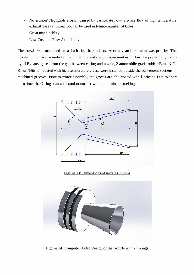
The nozzle was machined on a Lathe by the students. Accuracy and precision was priority. The
nozzle contour was rounded at the throat to avoid sharp discontinuities in flow. To prevent any blow-
by of Exhaust gases from the gap between casing and nozzle, 2 automobile grade rubber Buna N O-
Rings (Nitrile), coated with high temperature grease were installed outside the convergent sections in
machined grooves. Prior to motor assembly, the groves are also coated with lubricant. Due to short
burn time, the O-rings can withstand motor fire without burning or melting.
Figure 13: Dimensions of nozzle (in mm)
Figure 14: Computer Aided Design of the Nozzle with 2 O-rings
To prevent any further leakage, RTV sealant was used at the outside of nozzle near the casing walls.
The Nozzle had an expansion ratio of 10 allowing a nominal performance and making the nozzle
small.
Retention Ring: To retain the nozzle in the casing, a retention ring fabricated from the mild steel was
fabricated. The nozzle was retained in the casing by seating it on the ring, which was then screwed to
casing using six screws. The screws used were ¼”-20 x ½” Hex Head Cap screws of 18-8 Austenitic
stainless steel (ASTM-F593) due to higher shear strength of about 27810 N (413 MPa). At maximum
effective operating pressure (MEOP) of about 10.57 MPa, the force on each screw would be about
2678 N (shear stress of 39 MPa) at the designed thread shear area of 67.22 mm2. This provides a
safety factor of about 10.50, which is more than desirable. So, the retention ring won’t shear off even
in case of over-pressurization. The holes were tapped for matching threads on the retention ring. The
threads in the retaining ring were also strong enough to withstand a greater amount of stress than the
maximum possible design conditions being a Mild Steel material.
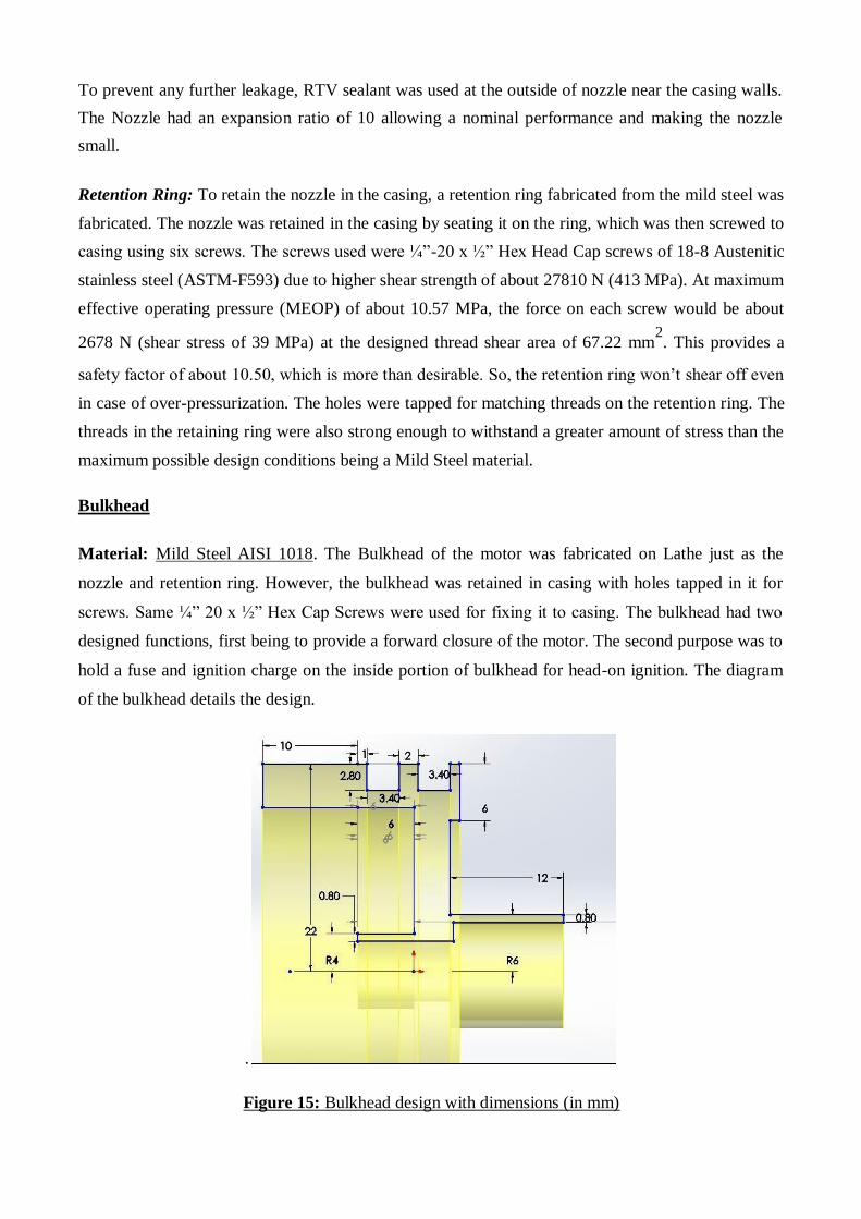
Bulkhead
Material: Mild Steel AISI 1018. The Bulkhead of the motor was fabricated on Lathe just as the
nozzle and retention ring. However, the bulkhead was retained in casing with holes tapped in it for
screws. Same ¼” 20 x ½” Hex Cap Screws were used for fixing it to casing. The bulkhead had two
designed functions, first being to provide a forward closure of the motor. The second purpose was to
hold a fuse and ignition charge on the inside portion of bulkhead for head-on ignition. The diagram
of the bulkhead details the design.
.
Figure 15: Bulkhead design with dimensions (in mm)
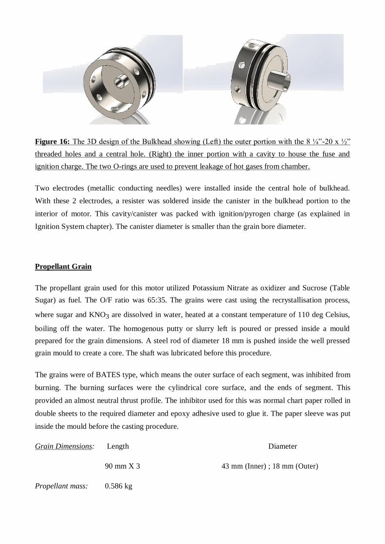
Figure 16: The 3D design of the Bulkhead showing (Left) the outer portion with the 8 ¼”-20 x ½”
threaded holes and a central hole. (Right) the inner portion with a cavity to house the fuse and
ignition charge. The two O-rings are used to prevent leakage of hot gases from chamber.
Two electrodes (metallic conducting needles) were installed inside the central hole of bulkhead.
With these 2 electrodes, a resister was soldered inside the canister in the bulkhead portion to the
interior of motor. This cavity/canister was packed with ignition/pyrogen charge (as explained in
Ignition System chapter). The canister diameter is smaller than the grain bore diameter.
Propellant Grain
The propellant grain used for this motor utilized Potassium Nitrate as oxidizer and Sucrose (Table
Sugar) as fuel. The O/F ratio was 65:35. The grains were cast using the recrystallisation process,
where sugar and KNO3 are dissolved in water, heated at a constant temperature of 110 deg Celsius,
boiling off the water. The homogenous putty or slurry left is poured or pressed inside a mould
prepared for the grain dimensions. A steel rod of diameter 18 mm is pushed inside the well pressed
grain mould to create a core. The shaft was lubricated before this procedure.
The grains were of BATES type, which means the outer surface of each segment, was inhibited from
burning. The burning surfaces were the cylindrical core surface, and the ends of segment. This
provided an almost neutral thrust profile. The inhibitor used for this was normal chart paper rolled in
double sheets to the required diameter and epoxy adhesive used to glue it. The paper sleeve was put
inside the mould before the casting procedure.
Grain Dimensions: Length Diameter
90 mm X 3 43 mm (Inner) ; 18 mm (Outer)
Propellant mass: 0.586 kg
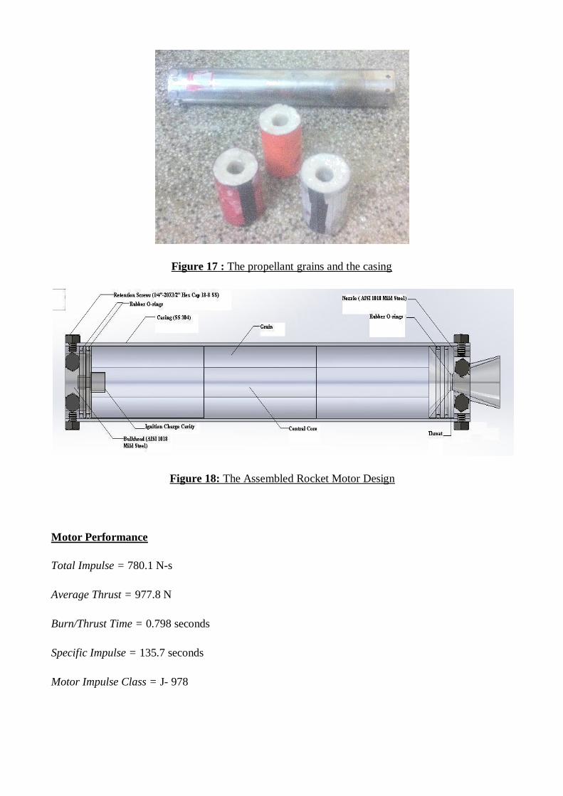
Figure 17 : The propellant grains and the casing
Figure 18: The Assembled Rocket Motor Design
Motor Performance
Total Impulse = 780.1 N-s
Average Thrust = 977.8 N
Burn/Thrust Time = 0.798 seconds
Specific Impulse = 135.7 seconds
Motor Impulse Class = J- 978
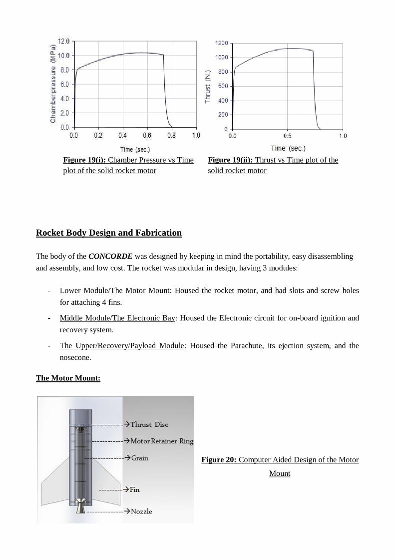
Figure 19(i): Chamber Pressure vs Time Figure 19(ii): Thrust vs Time plot of the
plot of the solid rocket motor solid rocket motor
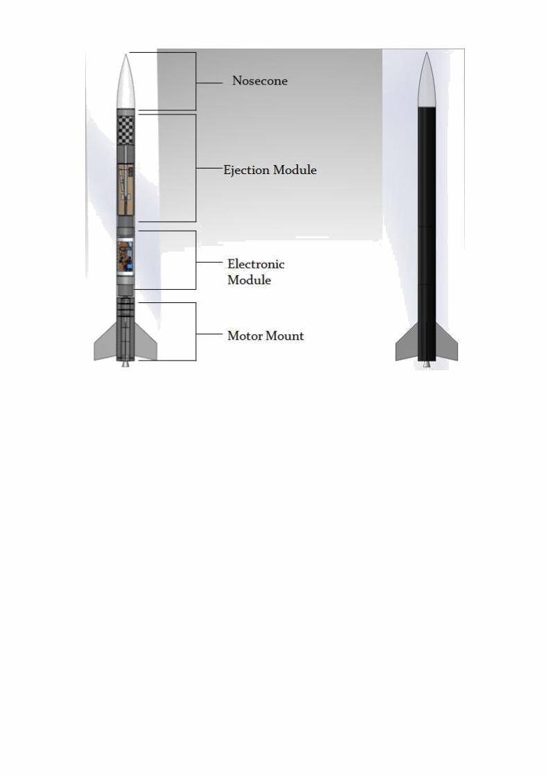
Rocket Body Design and Fabrication The body of the CONCORDE was designed by keeping in mind the portability, easy disassembling
and assembly, and low cost. The rocket was modular in design, having 3 modules:
- Lower Module/The Motor Mount: Housed the rocket motor, and had slots and screw holes
for attaching 4 fins.
- Middle Module/The Electronic Bay: Housed the Electronic circuit for on-board ignition and
recovery system.
- The Upper/Recovery/Payload Module: Housed the Parachute, its ejection system, and the
nosecone.
The Motor Mount:
Figure 20: Computer Aided Design of the Motor
Mount
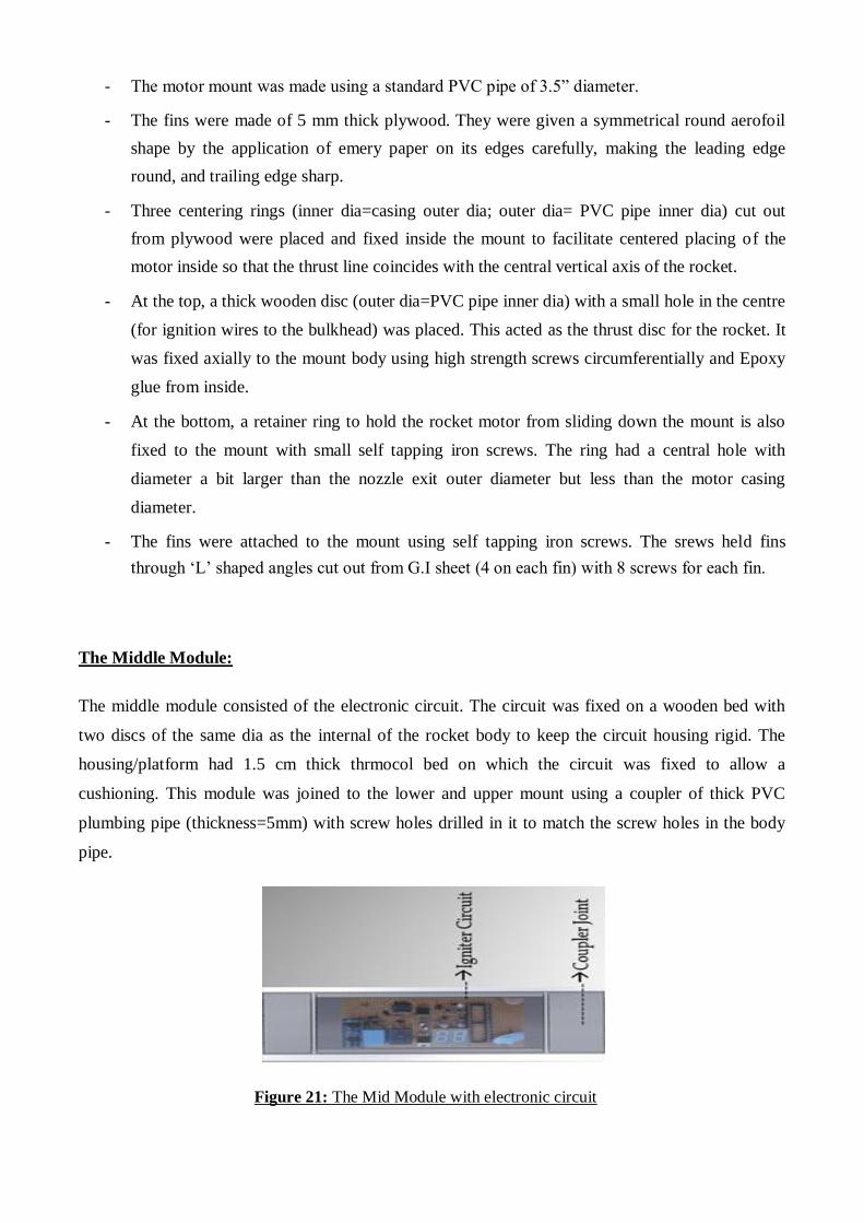
- The motor mount was made using a standard PVC pipe of 3.5” diameter.
- The fins were made of 5 mm thick plywood. They were given a symmetrical round aerofoil
shape by the application of emery paper on its edges carefully, making the leading edge
round, and trailing edge sharp.
- Three centering rings (inner dia=casing outer dia; outer dia= PVC pipe inner dia) cut out
from plywood were placed and fixed inside the mount to facilitate centered placing of the
motor inside so that the thrust line coincides with the central vertical axis of the rocket.
- At the top, a thick wooden disc (outer dia=PVC pipe inner dia) with a small hole in the centre
(for ignition wires to the bulkhead) was placed. This acted as the thrust disc for the rocket. It
was fixed axially to the mount body using high strength screws circumferentially and Epoxy
glue from inside.
- At the bottom, a retainer ring to hold the rocket motor from sliding down the mount is also
fixed to the mount with small self tapping iron screws. The ring had a central hole with
diameter a bit larger than the nozzle exit outer diameter but less than the motor casing
diameter.
- The fins were attached to the mount using self tapping iron screws. The srews held fins
through ‘L’ shaped angles cut out from G.I sheet (4 on each fin) with 8 screws for each fin.
The Middle Module:
The middle module consisted of the electronic circuit. The circuit was fixed on a wooden bed with
two discs of the same dia as the internal of the rocket body to keep the circuit housing rigid. The
housing/platform had 1.5 cm thick thrmocol bed on which the circuit was fixed to allow a
cushioning. This module was joined to the lower and upper mount using a coupler of thick PVC
plumbing pipe (thickness=5mm) with screw holes drilled in it to match the screw holes in the body
pipe.
Figure 21: The Mid Module with electronic circuit
The Upper Module: This module was the largest in length. It housed the parachute ejection system
and the parachute itself. The module had the nose cone at the top. The ejection system occupied most
of the upper module. The upper part was for the parachute which needed some good room in order to
come out easily. This required the module to be largest among other modules unlike in normal
rockets where payload area is the smallest.
Recovery system and Parachute
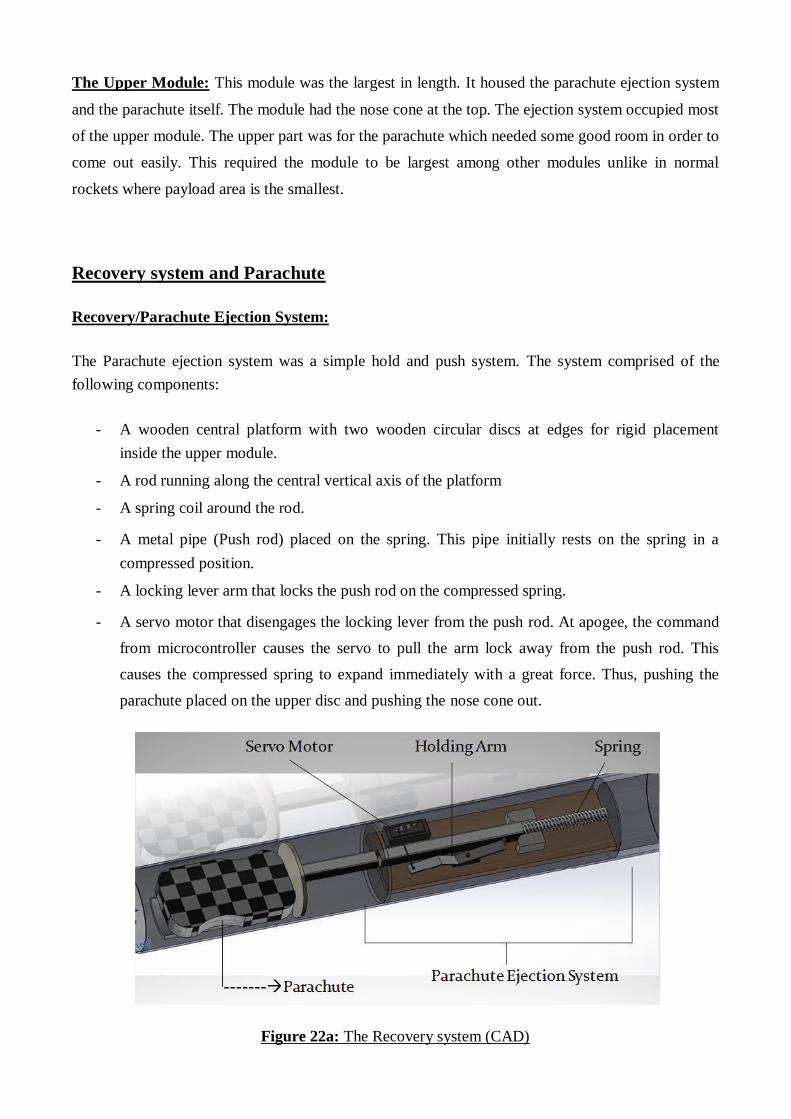
Recovery/Parachute Ejection System:
The Parachute ejection system was a simple hold and push system. The system comprised of the
following components:
- A wooden central platform with two wooden circular discs at edges for rigid placement
inside the upper module.
- A rod running along the central vertical axis of the platform
- A spring coil around the rod.
- A metal pipe (Push rod) placed on the spring. This pipe initially rests on the spring in a
compressed position.
- A locking lever arm that locks the push rod on the compressed spring.
- A servo motor that disengages the locking lever from the push rod. At apogee, the command
from microcontroller causes the servo to pull the arm lock away from the push rod. This
causes the compressed spring to expand immediately with a great force. Thus, pushing the
parachute placed on the upper disc and pushing the nose cone out.
Figure 22a: The Recovery system (CAD)
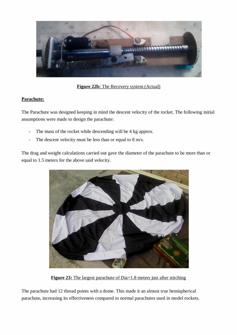
Figure 22b: The Recovery system (Actual)
Parachute:
The Parachute was designed keeping in mind the descent velocity of the rocket. The following initial
assumptions were made to design the parachute:
- The mass of the rocket while descending will be 4 kg approx.
- The descent velocity must be less than or equal to 8 m/s.
The drag and weight calculations carried out gave the diameter of the parachute to be more than or
equal to 1.5 meters for the above said velocity.
Figure 23: The largest parachute of Dia=1.8 meters just after stitching
The parachute had 12 thread points with a dome. This made it an almost true hemispherical
parachute, increasing its effectiveness compared to normal parachutes used in model rockets.
The Rocket CONCORDE
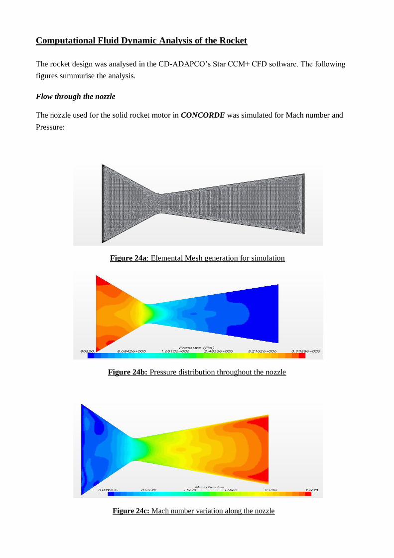
Computational Fluid Dynamic Analysis of the Rocket The rocket design was analysed in the CD-ADAPCO’s Star CCM+ CFD software. The following
figures summurise the analysis.
Flow through the nozzle
The nozzle used for the solid rocket motor in CONCORDE was simulated for Mach number and
Pressure:
Figure 24a: Elemental Mesh generation for simulation
Figure 24b: Pressure distribution throughout the nozzle
Figure 24c: Mach number variation along the nozzle
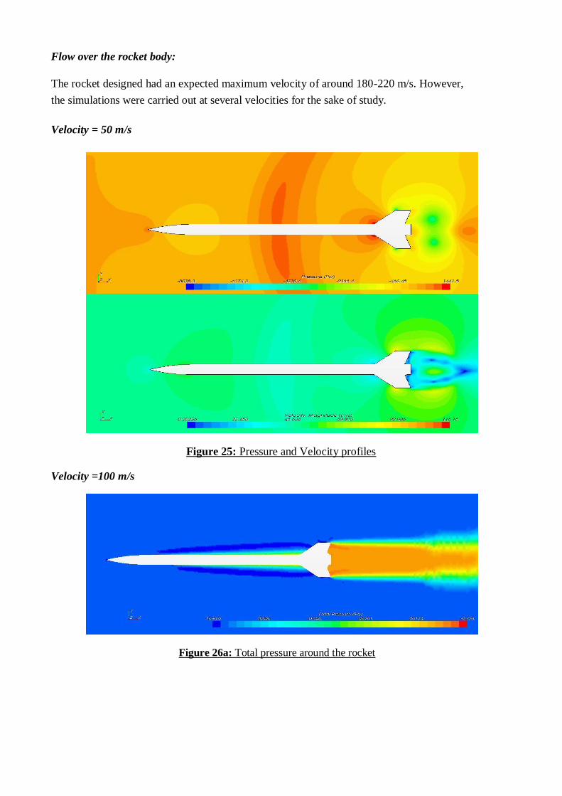
Flow over the rocket body:
The rocket designed had an expected maximum velocity of around 180-220 m/s. However,
the simulations were carried out at several velocities for the sake of study.
Velocity = 50 m/s
Figure 25: Pressure and Velocity profiles Velocity =100 m/s
Figure 26a: Total pressure around the rocket
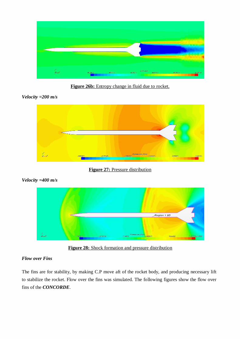
Figure 26b: Entropy change in fluid due to rocket.
Velocity =200 m/s
Figure 27: Pressure distribution Velocity =400 m/s
Figure 28: Shock formation and pressure distribution
Flow over Fins
The fins are for stability, by making C.P move aft of the rocket body, and producing necessary lift
to stabilize the rocket. Flow over the fins was simulated. The following figures show the flow over
fins of the CONCORDE.
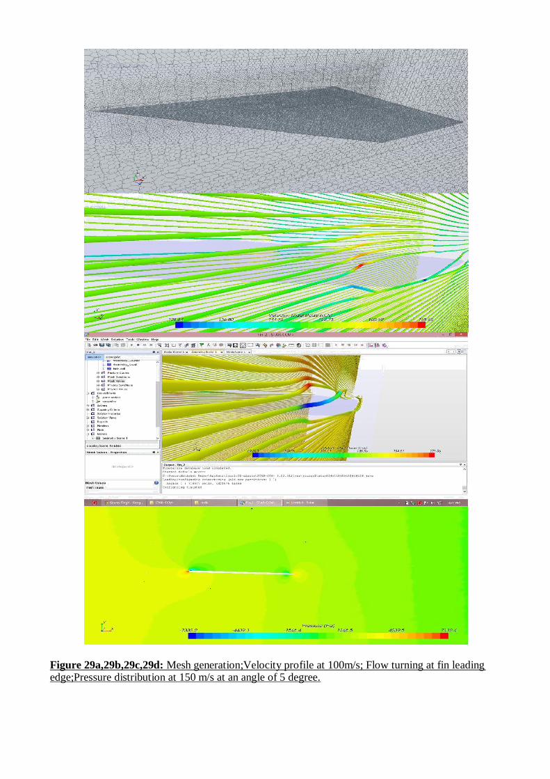
Figure 29a,29b,29c,29d: Mesh generation;Velocity profile at 100m/s; Flow turning at fin leading edge;Pressure distribution at 150 m/s at an angle of 5 degree.
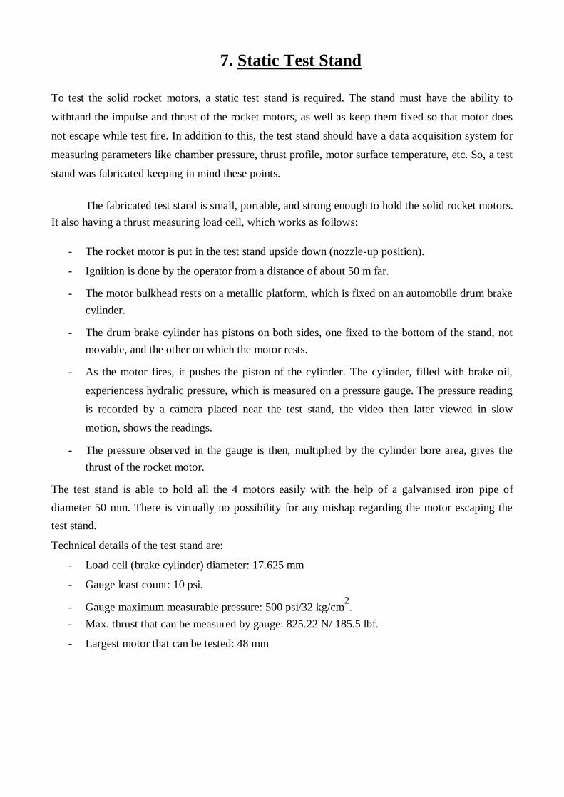
7. Static Test Stand To test the solid rocket motors, a static test stand is required. The stand must have the ability to
withtand the impulse and thrust of the rocket motors, as well as keep them fixed so that motor does
not escape while test fire. In addition to this, the test stand should have a data acquisition system for
measuring parameters like chamber pressure, thrust profile, motor surface temperature, etc. So, a test
stand was fabricated keeping in mind these points.
The fabricated test stand is small, portable, and strong enough to hold the solid rocket motors.
It also having a thrust measuring load cell, which works as follows:
- The rocket motor is put in the test stand upside down (nozzle-up position).
- Igniition is done by the operator from a distance of about 50 m far.
- The motor bulkhead rests on a metallic platform, which is fixed on an automobile drum brake
cylinder.
- The drum brake cylinder has pistons on both sides, one fixed to the bottom of the stand, not
movable, and the other on which the motor rests.
- As the motor fires, it pushes the piston of the cylinder. The cylinder, filled with brake oil,
experiencess hydralic pressure, which is measured on a pressure gauge. The pressure reading
is recorded by a camera placed near the test stand, the video then later viewed in slow
motion, shows the readings.
- The pressure observed in the gauge is then, multiplied by the cylinder bore area, gives the
thrust of the rocket motor. The test stand is able to hold all the 4 motors easily with the help of a galvanised iron pipe of
diameter 50 mm. There is virtually no possibility for any mishap regarding the motor escaping the
test stand. Technical details of the test stand are:
- Load cell (brake cylinder) diameter: 17.625 mm
- Gauge least count: 10 psi.
- Gauge maximum measurable pressure: 500 psi/32 kg/cm2.
- Max. thrust that can be measured by gauge: 825.22 N/ 185.5 lbf.
- Largest motor that can be tested: 48 mm
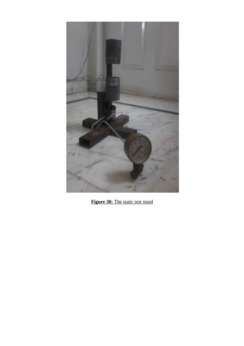
Figure 30: The static test stand
8. Tests And Analysis
Rocket Motor Static Tests Three Solid Rocket Motors were tested using the self-developed static test stand. The thrust was
measured by slowing down the recorded videos of the test. However, only the maximum thrust of the
motor could be measured with accuracy due to absence of an electronic data acquisition system. The
observations were only visual.
Sr. No Theoretical Max Measured Max Theoretical Burn Measured Burn
Thrust (N) Thrust (N) Time (s) Time (s)
Motor -1 977.8 798 0.798 1 s (approx)
(CONCORDE)
Motor -2 350 300 1.98 2 s (approx)
(CURIOSITY)
Motor -3 600 NA 1.358 1.45 s (approx)
(WAVERIDER)
Motor -4 550 495 1.280 1.32 s (approx)
(INDRA)
Motor -5 500 NA 1.128 1.25 s (approx)
(SKYLON)
Table 1: Rocket Motor Static Test Results
Static Test Images: Figure 31a & Figure 31b: Solid Rocket Motor of the CONCORDE and WAVERIDER
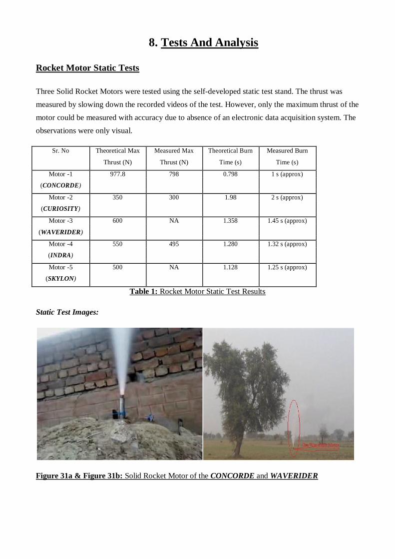
Figure 32: The Gauge reading during static test
of one of the motors (The gaug and camerae were
covered with bricks behind it to protect in case of
an explosion
Figure 31c,31d,31e : Solid rocket motors of CURIOSITY, SKYLON and INDRA
The post test analysis showed:
- No physical deformation
- Inhibitor worked flawlessly in all 5 motors
- Combustion residue left showing non-perfect but satisfactory combustion.
- Discoloration of the motor casing due to heat.
- No nozzle throat erosion
- Static Test Stand worked during three tests but leakage of brake fluid from load cell made
it impossible to obtain thrust data of two motors.
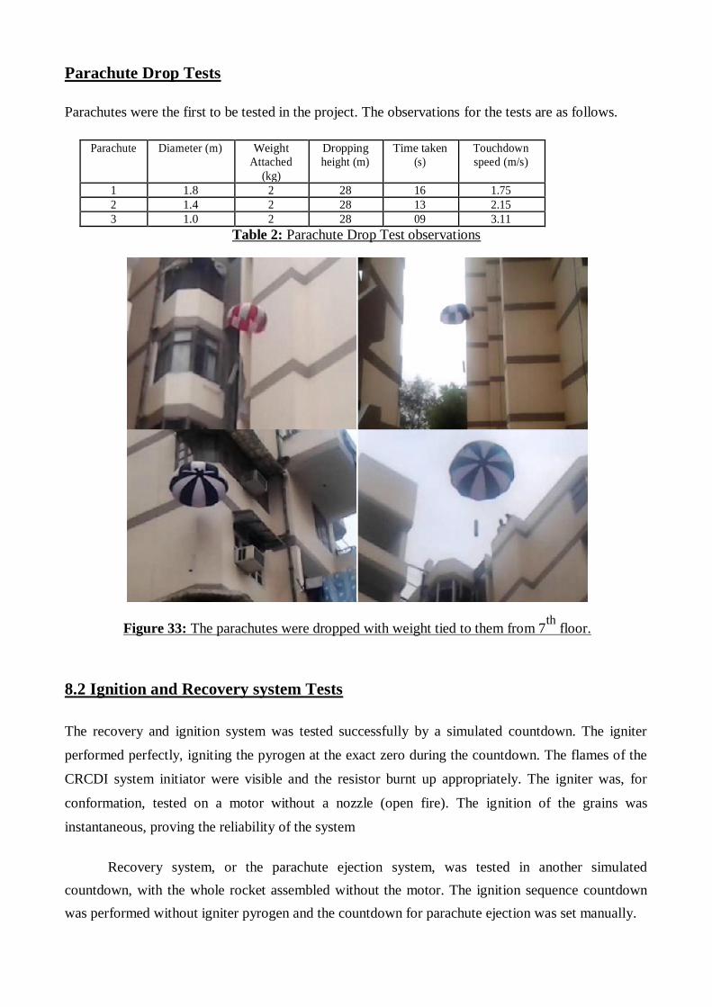
Parachute Drop Tests
Parachutes were the first to be tested in the project. The observations for the tests are as follows.
Parachute Diameter (m) Weight Dropping Time taken Touchdown
Attached height (m) (s) speed (m/s) (kg)
1 1.8 2 28 16 1.75 2 1.4 2 28 13 2.15 3 1.0 2 28 09 3.11
Table 2: Parachute Drop Test observations
Figure 33: The parachutes were dropped with weight tied to them from 7th
floor.
8.2 Ignition and Recovery system Tests The recovery and ignition system was tested successfully by a simulated countdown. The igniter
performed perfectly, igniting the pyrogen at the exact zero during the countdown. The flames of the
CRCDI system initiator were visible and the resistor burnt up appropriately. The igniter was, for
conformation, tested on a motor without a nozzle (open fire). The ignition of the grains was
instantaneous, proving the reliability of the system
Recovery system, or the parachute ejection system, was tested in another simulated
countdown, with the whole rocket assembled without the motor. The ignition sequence countdown
was performed without igniter pyrogen and the countdown for parachute ejection was set manually.
At the exact timing, after 15 seconds of the ignition, the ejection system successfully pushed out the
nose cone and with it the parachute. The force of the ejection system was observed to be more than
sufficient for a nose cone heavier than the one planned for use.
8.3 Propellant Burn Rate Tests
To assure best motor performance, it was necessary to validate the casted propellant’s performance. The solid propellant burn rate tests were carried out by developing a strand burner. The tests were
close to standard burn rate values.
A total of 11 test burns were made. Out of these, 1 test burn was done at the atmospheric pressure (0
psig) outside of the cylinder. A graph between the pressure and the burn rate was also plotted to
understand the effect. The observations are tabulated as follows:
Sr. Length Pressure in the burning Average Time recorded in the stopwatch (s) Average Burn
No. of the cylinder ‘Pg’ (psig) Pressure time ‘t’ Rate ‘b’
strand
‘P’ (psig)
(s) (mm/s)
Initial Final Stopwatch Stopwatch Stopwatch
‘l’(mm) pressure pressure 1 2 3
‘Pi’ ‘Pf’ ‘t1’ ‘t2’ ‘t3’
1. 84 0 0 0 32.38 31.97 32.20 32.18 2.610
2. 84 20 35 27.5 16.32 16.55 16.43 16.43 5.112
3. 84 60 77 68.5 10.44 10.56 10.67 10.56 7.954
4. 84 100 114 107 8.80 8.78 9.02 8.87 9.470
5. 84 140 157 148.5 9.50 9.75 9.64 9.63 8.722
6. 84 180 196 188 10.42 10.57 10.31 10.43 8.053
7. 84 220 235 227.5 10.43 10.65 10.70 10.59 7.932
8. 84 260 277 268.5 10.50 10.64 10.68 10.60 7.924
9. 84 300 315 307.5 10.65 10.72 10.79 10.72 7.836
10. 84 340 355 347.5 10.68 10.76 10.80 10.74 7.821
11. 84 380 394 387 10.77 10.82 10.79 10.79 7.785
Table 3: Data Obtained from the Experiment
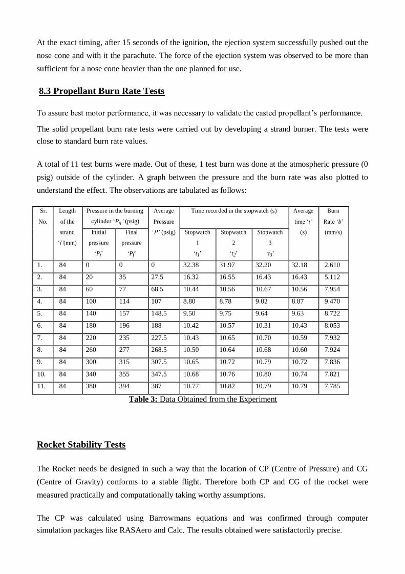
Rocket Stability Tests The Rocket needs be designed in such a way that the location of CP (Centre of Pressure) and CG
(Centre of Gravity) conforms to a stable flight. Therefore both CP and CG of the rocket were
measured practically and computationally taking worthy assumptions.
The CP was calculated using Barrowmans equations and was confirmed through computer
simulation packages like RASAero and Calc. The results obtained were satisfactorily precise.

CP calculation involved the following physical parameters of the rocket body.
All the measurements are in inches.
Nose Cone Type: Ojive
Nose Cone Length: 10.64
Nose Tip Radius: 0.09
Max Diameter: 3.6
Body Tube Length: 3.6
Nozzle Exit Diameter: 1.4
Launch Lug Diameter: 1.0
Fin Root Chord: 6.1160
Fin Tip Chord: 2.84
Fin Sweep Distance: 4.1760
Fin Span: 3.360
Number of Fins: 4
Fin Location (From Nose Tip): 56.72
Airfoil Type: Biconvex
Fin Thickness: 0.120
Fin Leading Edge Radius: 0.04
Fin Can Length: 0
Type of Surface Finish: Smooth Painted
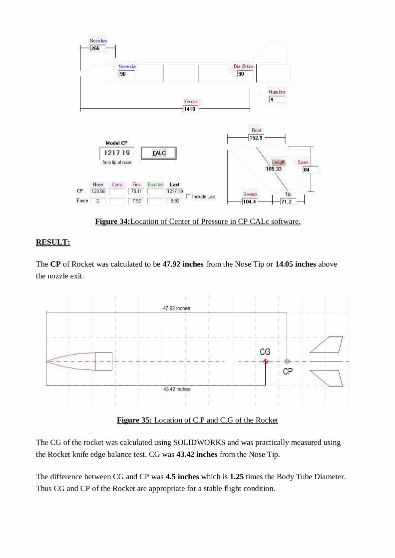
Figure 34:Location of Center of Pressure in CP CALc software.
RESULT:
The CP of Rocket was calculated to be 47.92 inches from the Nose Tip or 14.05 inches above
the nozzle exit.
Figure 35: Location of C.P and C.G of the Rocket
The CG of the rocket was calculated using SOLIDWORKS and was practically measured using
the Rocket knife edge balance test. CG was 43.42 inches from the Nose Tip.
The difference between CG and CP was 4.5 inches which is 1.25 times the Body Tube Diameter.
Thus CG and CP of the Rocket are appropriate for a stable flight condition.
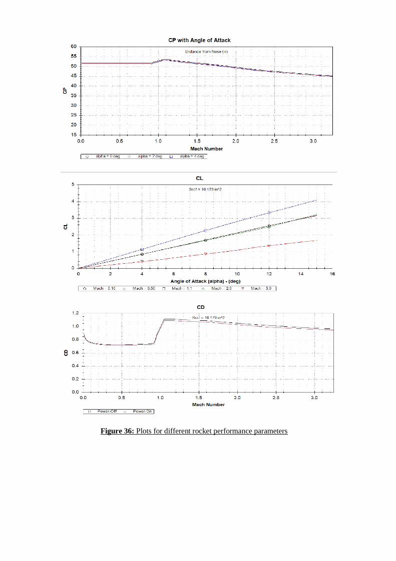
Figure 36: Plots for different rocket performance parameters
9. Launch
Launch Site The selection launch site for the launch was a difficult part of the project. For convenience,
the launch and static test site were to be same. The following were the requirements:
- A vast field with no public/private property in a circular area with a radius of at least 1 km
from the launch point.
- No overhead wirings or power cables
- Easily accessible for a Fire Brigade Truck.
- A temporary kiosk facility for propellant casting and storing.
After a time consuming search, the launch site was decided to be a filed in Village Surajpur, Tehsil Dharuhera, Distt. Rewari, Haryana.
Launch Pad Considering the size of the rockets, there was no need for a concrete or larger launch pad. However,
to ensure rigid support before launch and provide a guide rail for maintaining a straight flight path
just after ignition, launch rail must be provided. This was done by fixing a Steel Pipe of diameter
equal to 2 cm. This pipe was fixed in the ground by digging at least 3 ft under the ground surface.
This ensured rigid support for the rockets.
A launch lug was screwed on each rocket. The lug was made with a 7 cm cut out of a PVC
electrical conduit pipe with a dia a bit larger than the steel launch pipe. This made the launch lug
slide easily on the launch pipe.
Range Safety The Range Safety protocol was well conveyed to all the persons at the launch site and was also well
rehearsed. The protocol was as follows:
- After the rocket was installed on the launch pad, the launch area was condoned. Except
the project team, all other (spectators, police, firemen etc.) were at least 600 meters away.
- Pre-launch checks included the ignition circuit check (a free ignition was done to assure
that ignition will occur as per countdown.), wire connections, battery voltage checks, and
some other checks.
- The Air Traffic Controllers of the nearest airport were continuously informed about the
status of the launch sequence via mobile conversations.
- The High Energy Capacitor of the igniter circuit was charged using 4 AA cells. This
was done only after all range safety precautions were taken.
- After the capacitor was charged, a 1 minute countdown was started. This was Verbally
shouted by one of the helpers of the project team. The count was shouted after every 5
seconds till T-15 seconds, and then a continuous countdown was shouted till the launch.
- After the flight, no one was allowed to rush to the landing site/crash site of the rocket except
2 members of the project team.
- In case of any mishap, a fire brigade and an ambulance were present to provide assistance.
- The whole procedure was repeated for all the launches.
Post Launch Analysis The launch of the five rockets was attempted on 2 consecutive days. Small glitches and snags during
pre-launch preparation caused the launch to be postponed to second day.
On the second/last day of the launch window, All 5 rockets were assembled at the launch site. Pre-
flight check-ups were done on time. The following is the summary of the events in chronological
order.
1st
Launch attempt: SKYLON
- Ignition charge and wire put through the nozzle of the rocket. A very small length of cello-
tape is put over the nozzle to keep the igniter lead from sliding down. A brick is kept on leads
a few feet away from the rocket in order to detach the leads from rocket.
- The rocket is slid down on the launch rod with the lug.
- The High Energy Capacitor charged to 250 V, and countdown of 1 min started.
- Ignition charge fires, but motor didn’t start. After 3 min wait, the ignition leads are
manually removed.
2nd
Launch attempt: SKYLON
- Another pyrotechnic igniter connected with igniter leads, and put through nozzle.
- Countdown started, and at T-0, ignition charge fires, but motor didn’t start.
- Igniter leads removed manually after a 3min safety period.
3rd
Launch attempt: SKYLON
- New igniter put inside the motor through the nozzle.
- Igniter fires. Motor propellant fails to ignite again.
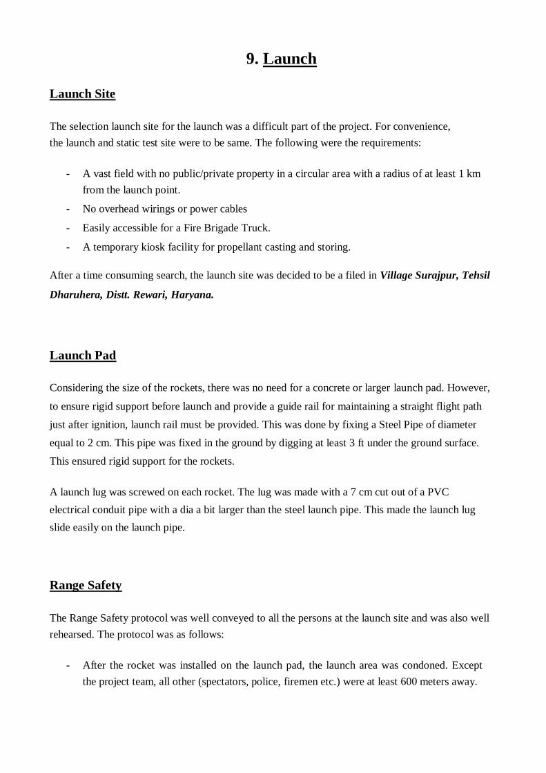
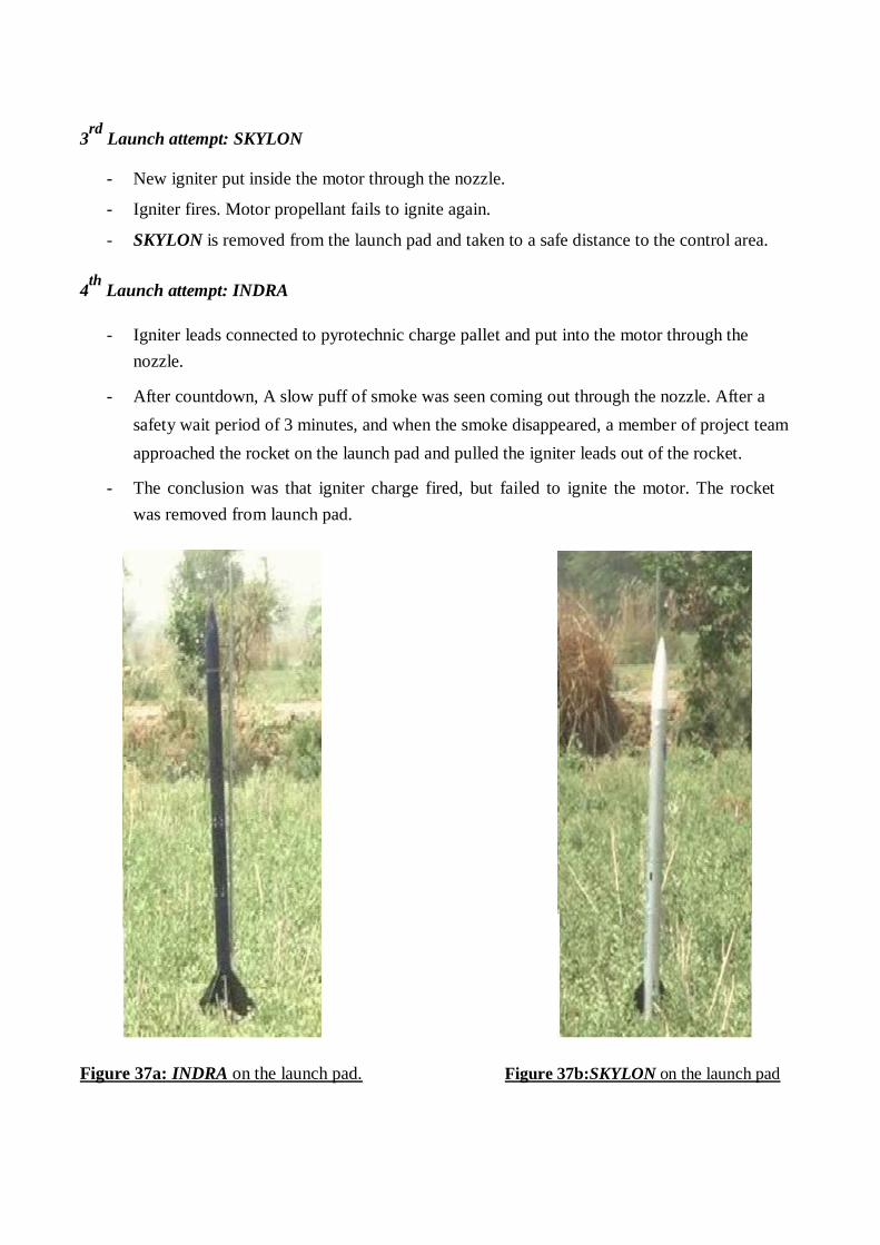
- SKYLON is removed from the launch pad and taken to a safe distance to the control area.
4th
Launch attempt: INDRA
- Igniter leads connected to pyrotechnic charge pallet and put into the motor through the
nozzle.
- After countdown, A slow puff of smoke was seen coming out through the nozzle. After a
safety wait period of 3 minutes, and when the smoke disappeared, a member of project team
approached the rocket on the launch pad and pulled the igniter leads out of the rocket.
- The conclusion was that igniter charge fired, but failed to ignite the motor. The rocket
was removed from launch pad.
Figure 37a: INDRA on the launch pad. Figure 37b:SKYLON on the launch pad
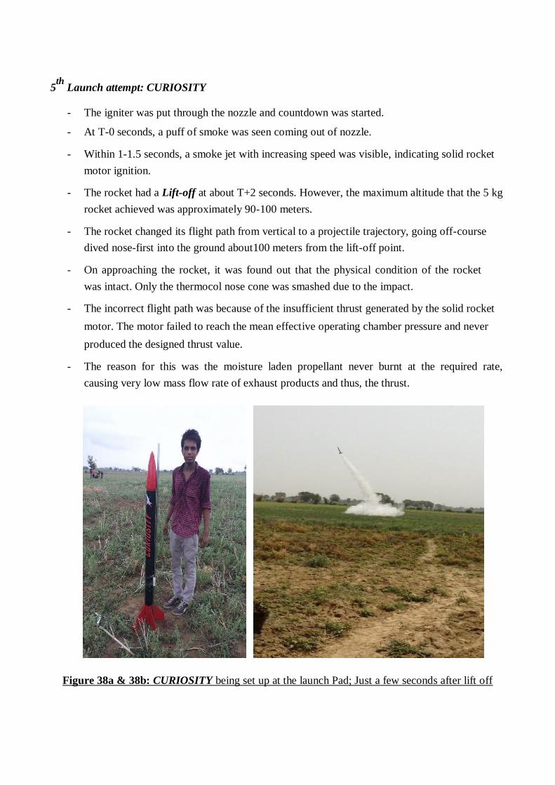
5th
Launch attempt: CURIOSITY
- The igniter was put through the nozzle and countdown was started.
- At T-0 seconds, a puff of smoke was seen coming out of nozzle.
- Within 1-1.5 seconds, a smoke jet with increasing speed was visible, indicating solid rocket
motor ignition.
- The rocket had a Lift-off at about T+2 seconds. However, the maximum altitude that the 5 kg
rocket achieved was approximately 90-100 meters.
- The rocket changed its flight path from vertical to a projectile trajectory, going off-course
dived nose-first into the ground about100 meters from the lift-off point.
- On approaching the rocket, it was found out that the physical condition of the rocket
was intact. Only the thermocol nose cone was smashed due to the impact.
- The incorrect flight path was because of the insufficient thrust generated by the solid rocket
motor. The motor failed to reach the mean effective operating chamber pressure and never
produced the designed thrust value.
- The reason for this was the moisture laden propellant never burnt at the required rate,
causing very low mass flow rate of exhaust products and thus, the thrust.
Figure 38a & 38b: CURIOSITY being set up at the launch Pad; Just a few seconds after lift off
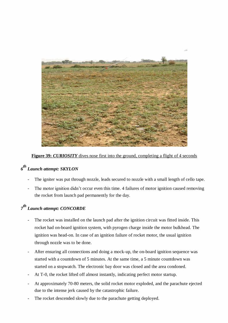
Figure 39: CURIOSITY dives nose first into the ground, completing a flight of 4 seconds
6th
Launch attempt: SKYLON
- The igniter was put through nozzle, leads secured to nozzle with a small length of cello tape.
- The motor ignition didn’t occur even this time. 4 failures of motor ignition caused removing
the rocket from launch pad permanently for the day.
7th
Launch attempt: CONCORDE
- The rocket was installed on the launch pad after the ignition circuit was fitted inside. This
rocket had on-board ignition system, with pyrogen charge inside the motor bulkhead. The
ignition was head-on. In case of an ignition failure of rocket motor, the usual ignition
through nozzle was to be done.
- After ensuring all connections and doing a mock-up, the on-board ignition sequence was
started with a countdown of 5 minutes. At the same time, a 5 minute countdown was
started on a stopwatch. The electronic bay door was closed and the area condoned.
- At T-0, the rocket lifted off almost instantly, indicating perfect motor startup.
- At approximately 70-80 meters, the solid rocket motor exploded, and the parachute ejected
due to the intense jerk caused by the catastrophic failure.
- The rocket descended slowly due to the parachute getting deployed.
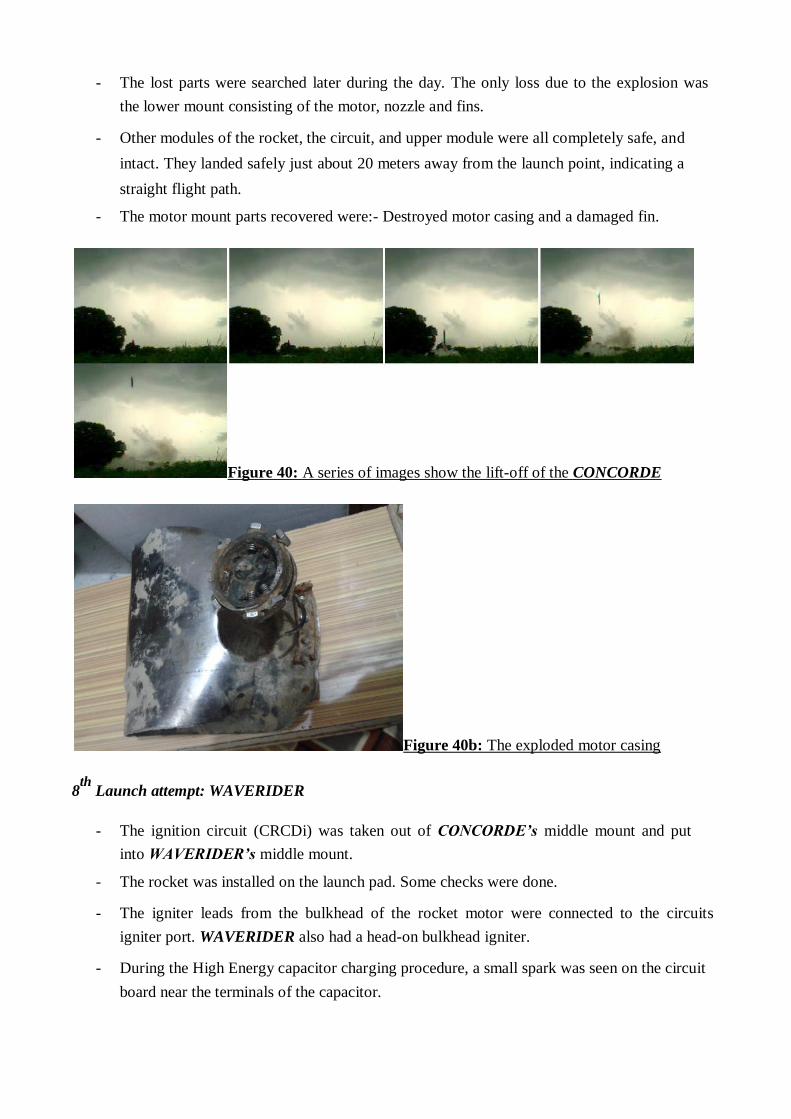
- The lost parts were searched later during the day. The only loss due to the explosion was
the lower mount consisting of the motor, nozzle and fins.
- Other modules of the rocket, the circuit, and upper module were all completely safe, and
intact. They landed safely just about 20 meters away from the launch point, indicating a
straight flight path.
- The motor mount parts recovered were:- Destroyed motor casing and a damaged fin.
Figure 40: A series of images show the lift-off of the CONCORDE
Figure 40b: The exploded motor casing
8th
Launch attempt: WAVERIDER
- The ignition circuit (CRCDi) was taken out of CONCORDE’s middle mount and put
into WAVERIDER’s middle mount.
- The rocket was installed on the launch pad. Some checks were done.
- The igniter leads from the bulkhead of the rocket motor were connected to the circuits
igniter port. WAVERIDER also had a head-on bulkhead igniter.
- During the High Energy capacitor charging procedure, a small spark was seen on the circuit
board near the terminals of the capacitor.
- The igniter leads were immediately disconnected from the circuit and the launch
sequence was paused.
- After repeated charging-discharging cycles, it was found out that due to the impact of the
previous launch of CONCORDE, the circuit suffered a shock jerk, which caused the
capacitor terminal getting disconnected from the circuit board. The solder joint got broken.
As a result, the capacitor was not charging, and a short was created between two solder joints.
- As a result of the diagnosis, the launch window expired, and all further launches
were cancelled.
This concluded the Launch Portion of the project. With 2 rockets getting launched, the project was a partial success.
10. Legal Permissions
Rules
Rules for Possessing, casting of Propellants
- The propellant, as per the Explosives Act of India, 1983, falls under the category of low
explosives that burn by deflagration.
- For the project, the permission was sought under the Explosives Rules, 2008, Govt. of India.
- The Chapter 3, Rule 9 of these rules has an exception for small amount of explosives
intended to be tested in an established laboratory.
- The permission is granted by Petroleum and Safety Organization (P.E.S.O), Govt. of India.
Rules for Rocket Launch
- No rules exist in India currently for Model or Amateur Rocket Launches.
- However, any object, flying above 1000 feet, requires air clearance from the Air Traffic
Control of the nearest Airport.
- This is done after prior approval of the event from Director General of Civil Aviation.
- A NOTAM is generated for the event.
Permissions
The permissions that were obtained for casting propellants and launching of rocket for this experimental project are:
1) The No-Objection Certificate (Affidavit) by the owner of the launch site/test site where
propellant was to be manufactured and rockets were to be launched claiming that he/she
owns the land and has no objection in the experiment being carried out on his/her land.
2) No-Objection Certificate by the Chief Controller of Explosives, Petroleum and Explosives
Safety Organisation (P.E.S.O), Govt. of India that the propellant is authorized and can be
used for the project on several conditions.
3) A No-Objection Certificate by the District Magistrate of the District where the launch site
belongs to. This N.O.C is obtained by Individual verifications by the following:
- Land ownership verification by Patwari of the village where the launch site is located.
- Police Verification by Local Police and the S.H.O of the Tehsil.

- Verification and validation by the Fire Dept. of the district for the event on condition that a
fire brigade must be present on the event.
4) Event approval from Director General of Civil Aviation. 5) NOTAM Generation by the Air Traffic Control of nearest airport and Live Event Co-
Ordination with the controllers from the event. (On Launch Day)

11. Conclusion The whole project served its many purposes. It served to:
- Successfully understand and learn the application of concepts in subjects like embedded
electronics, Propulsion systems, Aerodynamics, Flight Dynamics, Structures
- Learn practical intricacies of handling propellants, safety precautions, quality control,
propellant casting techniques, motor fabrications.
- Learn and become fluent in use of manufacturing machines like Lathe, Drills, Milling
machines, etc.
- Rules of rocketry, launch and propellant rules throughout the world and Indian scenario.
- Launch conditions, recovery systems, parachute design
- Understanding the potential of Amateur rocketry as a great academic activity for learning and
hobby purposes.
Overall, the project was the greatest learning experience throughout the degree of the students which made both the students and the institute proud.
12. Appendices
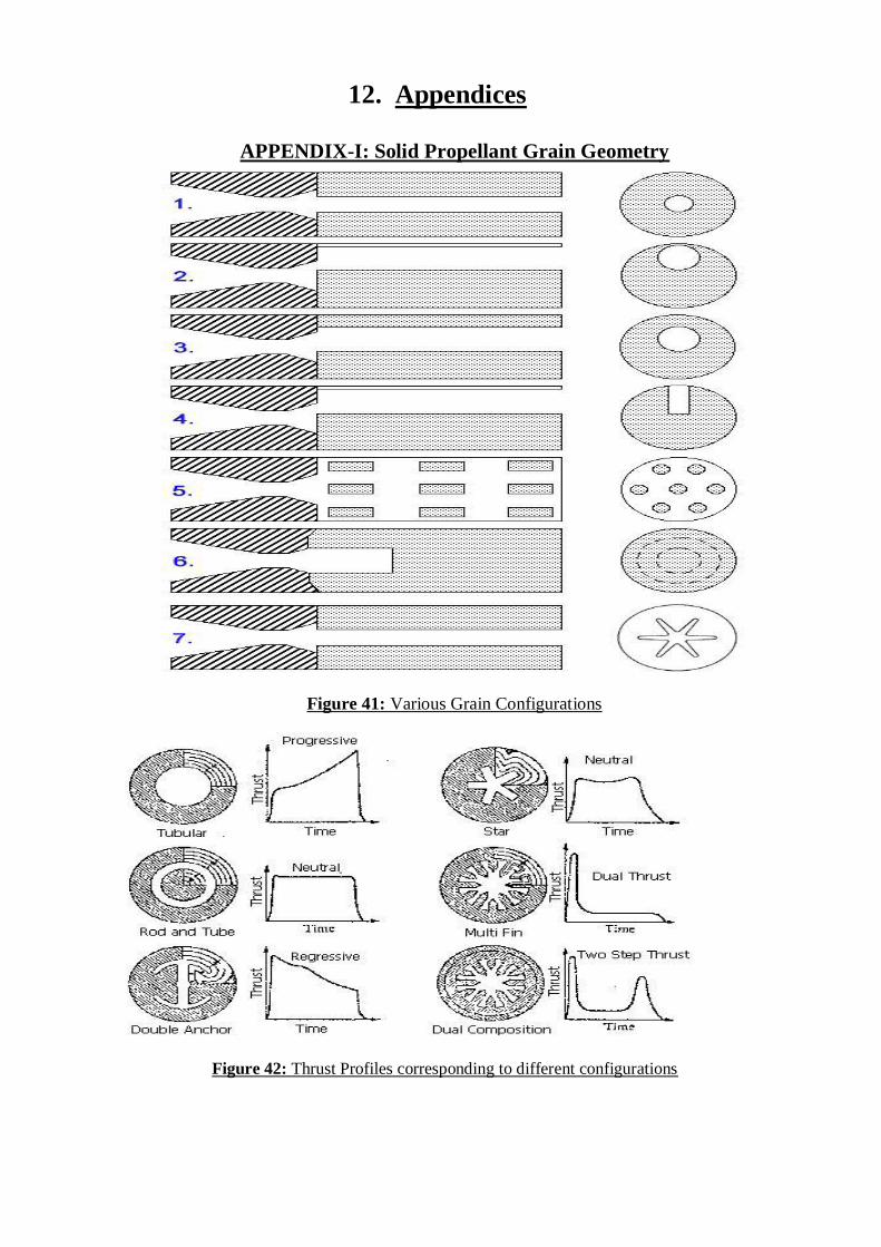
APPENDIX-I: Solid Propellant Grain Geometry
Figure 41: Various Grain Configurations Figure 42: Thrust Profiles corresponding to different configurations
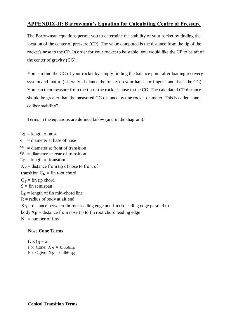
APPENDIX-II: Barrowman’s Equation for Calculating Centre of Pressure
The Barrowman equations permit you to determine the stability of your rocket by finding the location of the center of pressure (CP). The value computed is the distance from the tip of the rocket's nose to the CP. In order for your rocket to be stable, you would like the CP to be aft of the center of gravity (CG). You can find the CG of your rocket by simply finding the balance point after loading recovery system and motor. (Literally - balance the rocket on your hand - or finger - and that's the CG). You can then measure from the tip of the rocket's nose to the CG. The calculated CP distance should be greater than the measured CG distance by one rocket diameter. This is called "one caliber stability". Terms in the equations are defined below (and in the diagram): = length of nose = diameter at base of nose = diameter at front of transition
= diameter at rear of transition
= length of transition XP = distance from tip of nose to front of
transition CR = fin root chord
CT = fin tip chord
S = fin semispan
LF = length of fin mid-chord line
R = radius of body at aft end
XR = distance between fin root leading edge and fin tip leading edge parallel to
body XB = distance from nose tip to fin root chord leading edge N = number of fins
Nose Cone Terms
(CN)N = 2
For Cone: XN = 0.666LN
For Ogive: XN = 0.466LN
Conical Transition Terms
LT
d
dF
dR
LN
Fin Terms
Finding the Center of Pressure
Sum up coefficients: (CN)R = (CN)N + (CN)T + (CN)F Find CP Distance from Nose Tip:
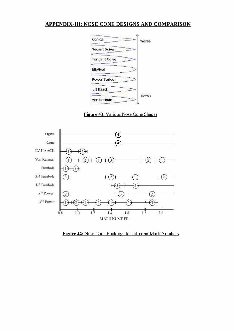
APPENDIX-III: NOSE CONE DESIGNS AND COMPARISON
Figure 43: Various Nose Cone Shapes
Figure 44: Nose Cone Rankings for different Mach Numbers

APPENDIX-IV: Programme code for ignition and recovery
system (CRCDI) ATmega32 PROGRAM CODE
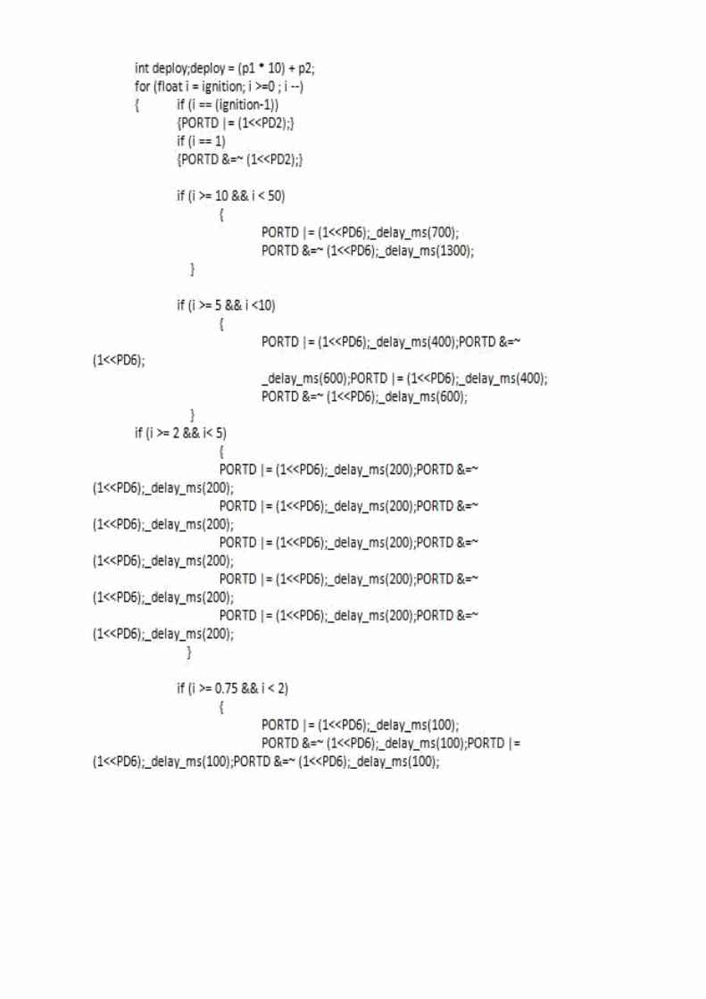
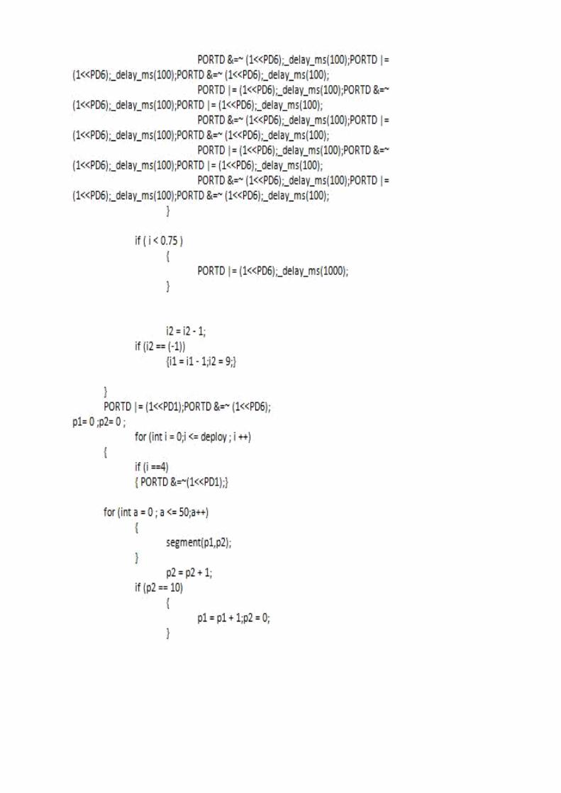
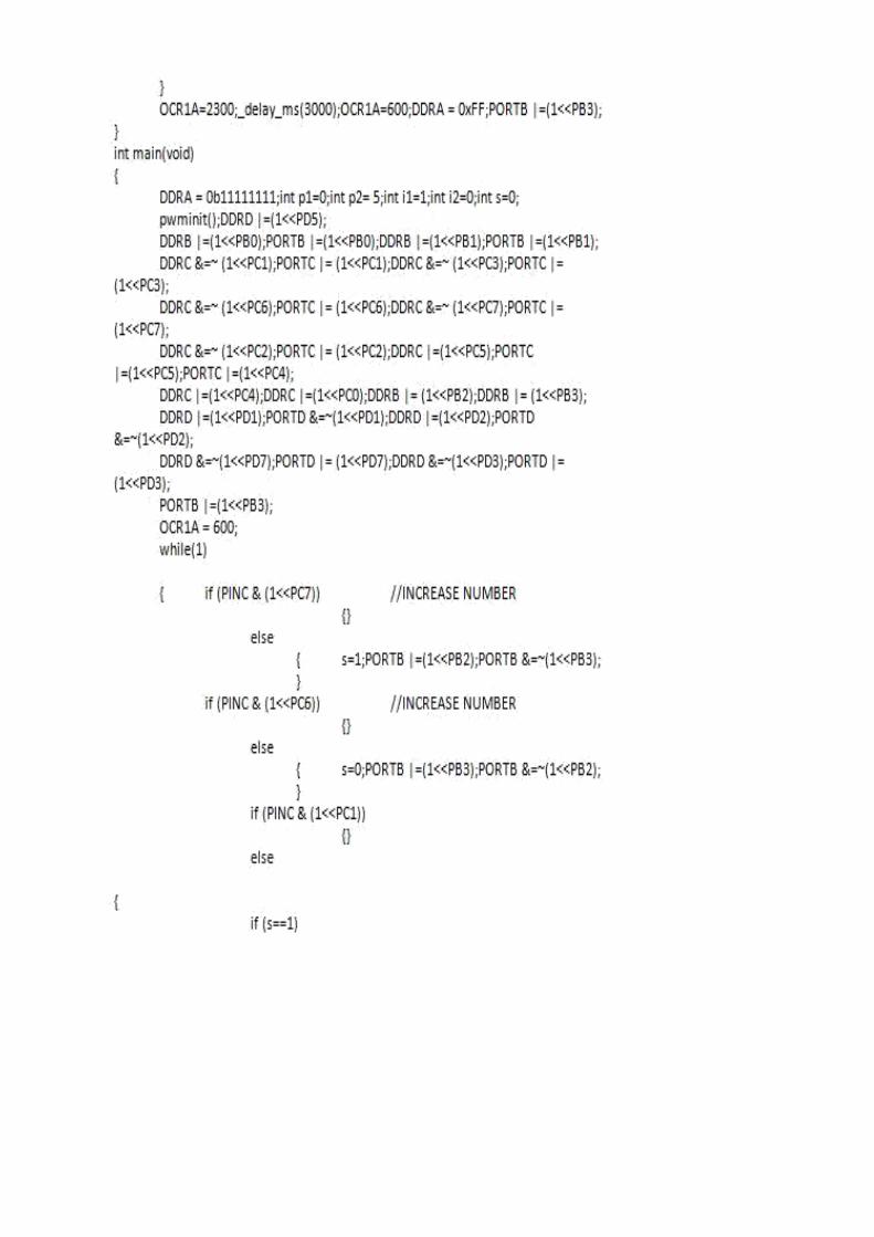
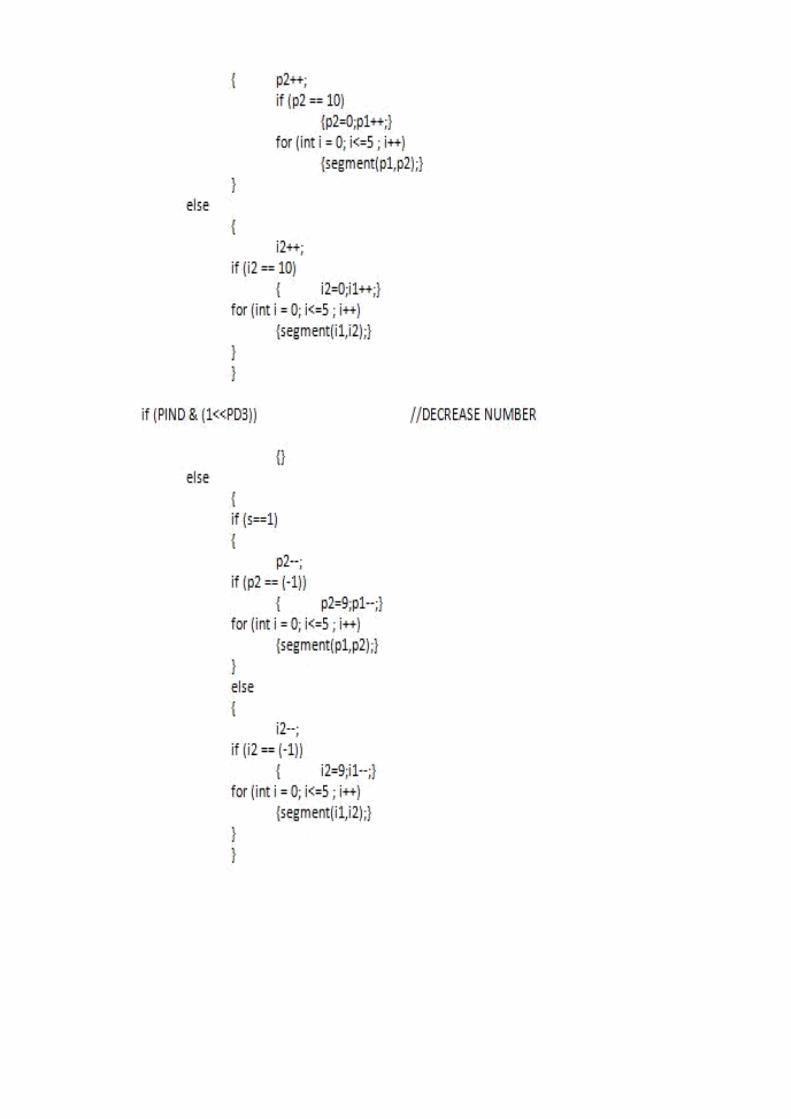
APPENDIX-V: Photos of fabricated rocket components
The Project Team of 3 students
Electronic Circuits of the rockets
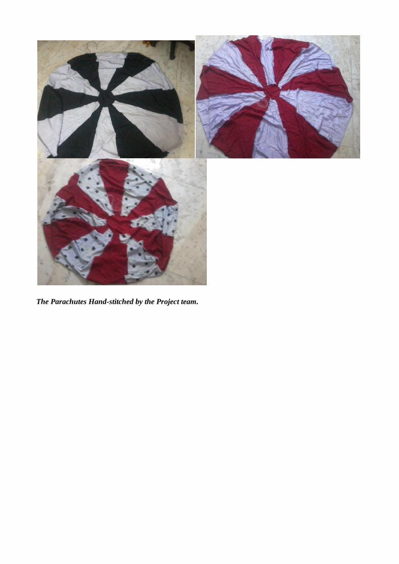
The Parachutes Hand-stitched by the Project team.
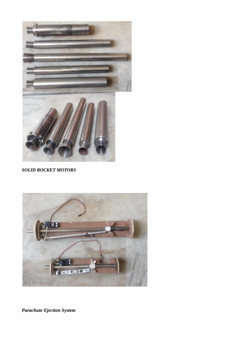
SOLID ROCKET MOTORS
Parachute Ejection System
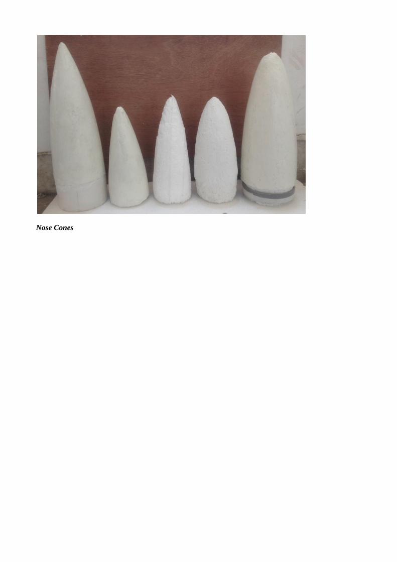
Nose Cones
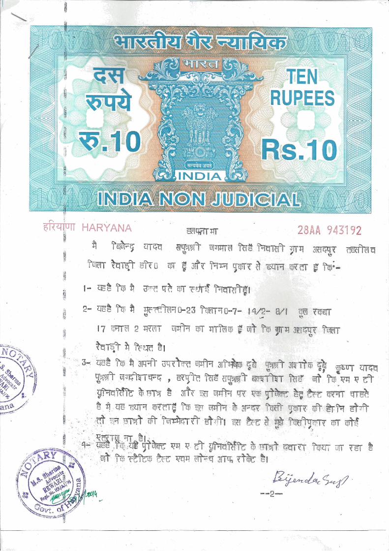
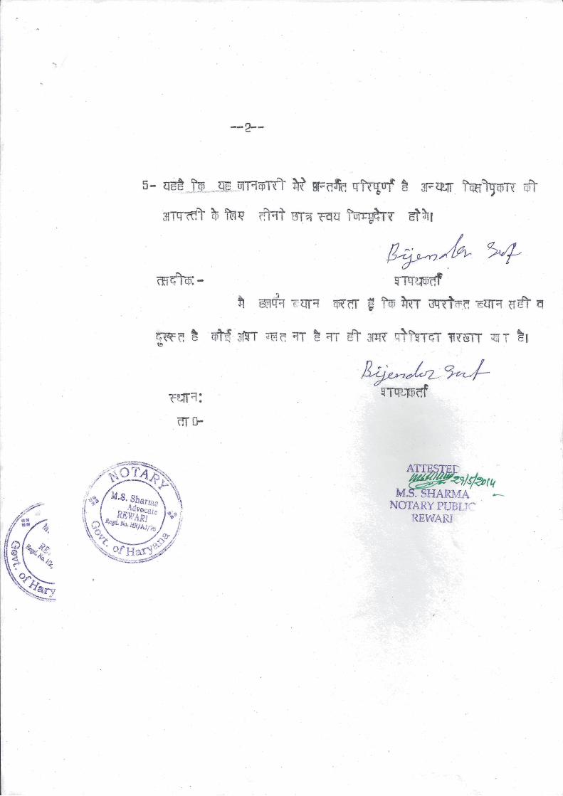

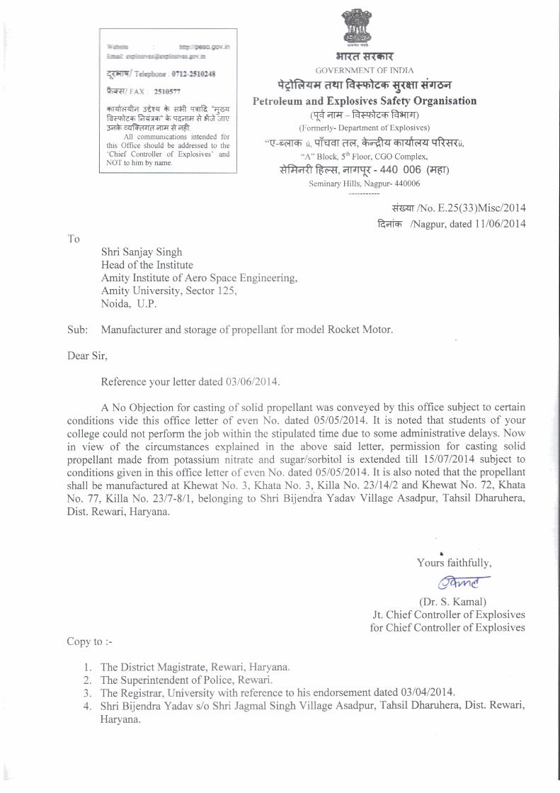
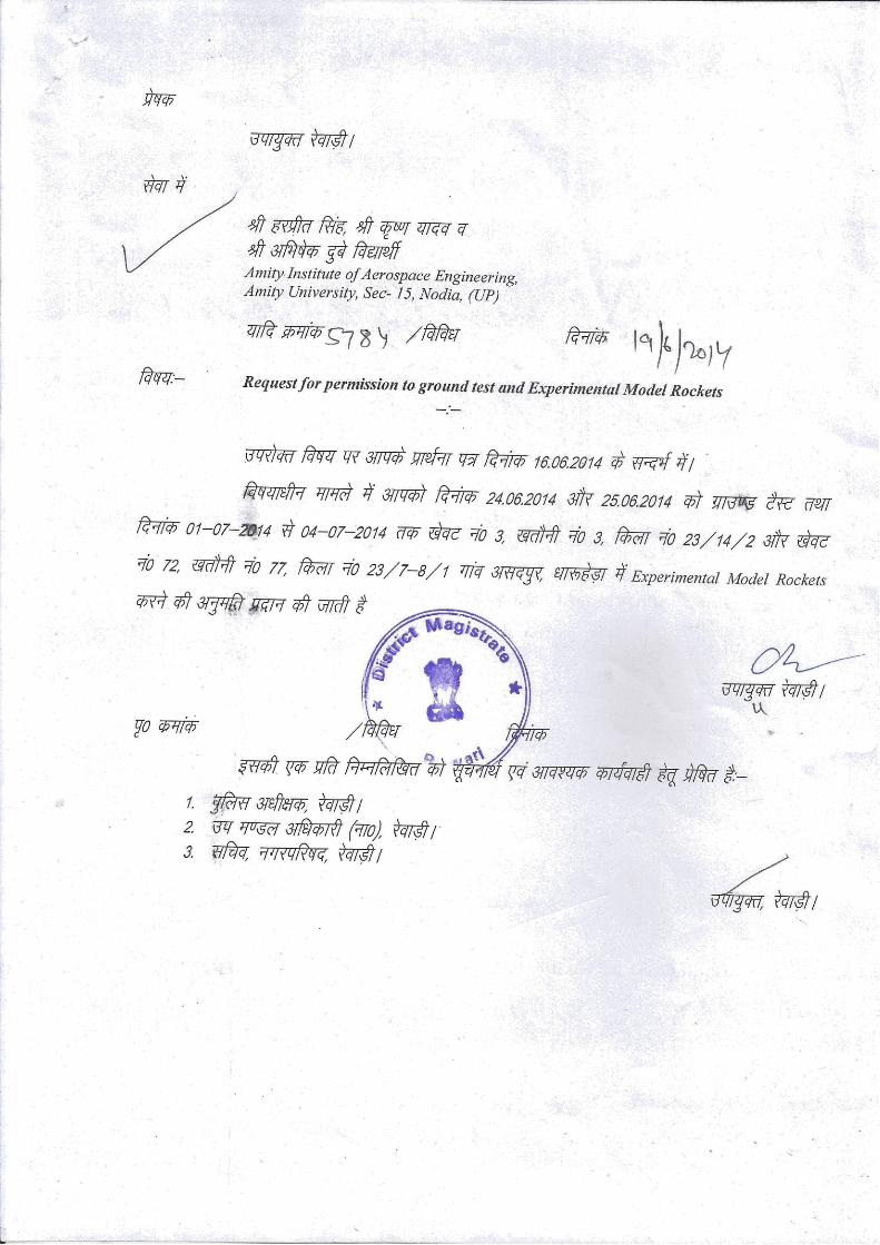

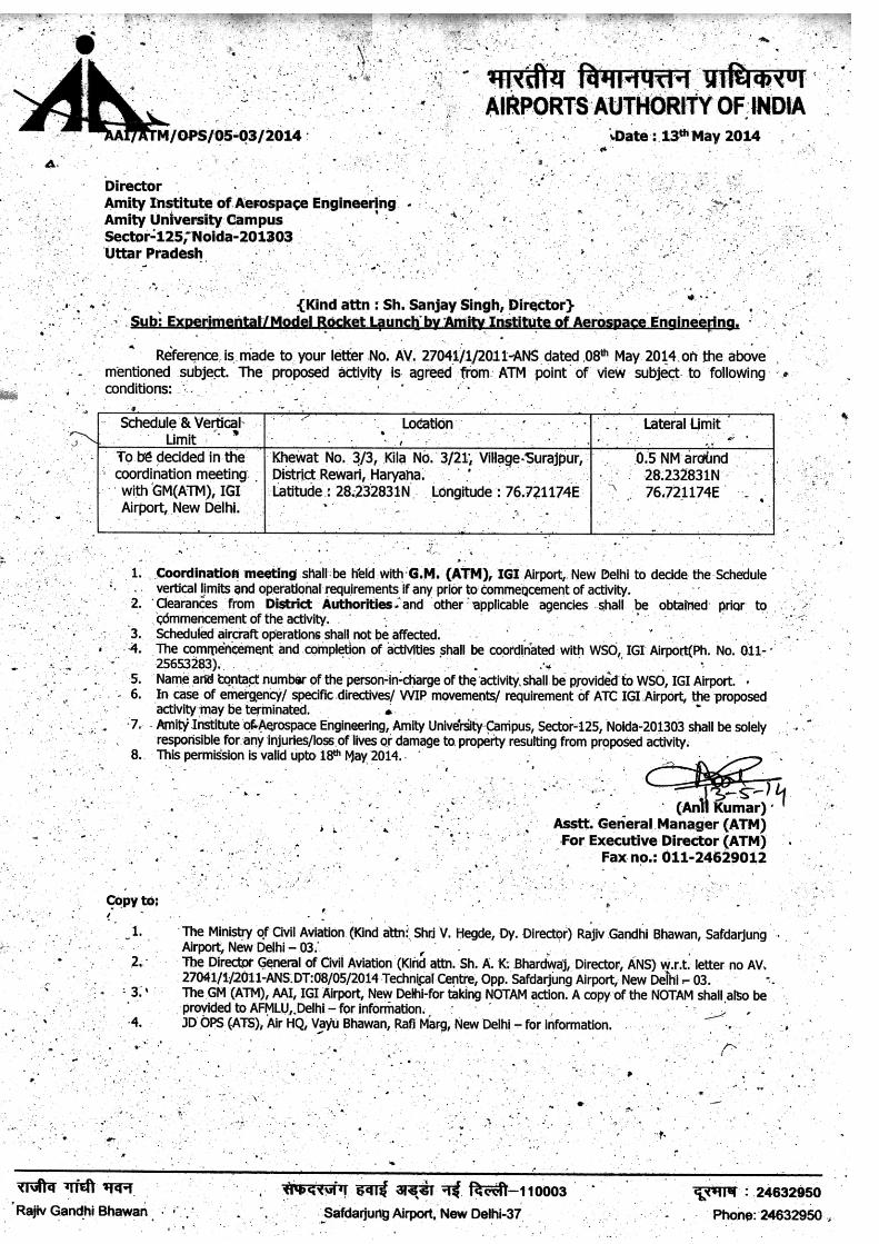
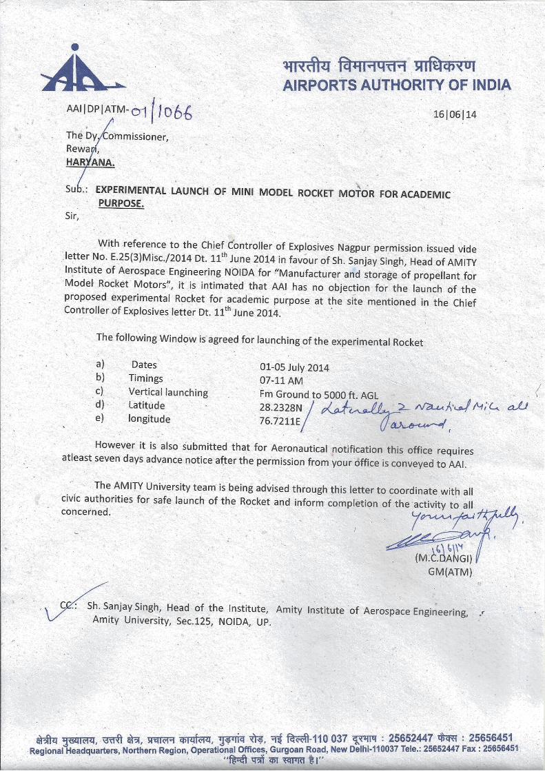


![Amateur Operato Advanced - Australian Maritime College · Amateur Operato Advanced Syllabus and Examination. The Amateur Licence (amateur advanced station) [the Advanced Amateur Licence]](https://static.fdocuments.us/doc/165x107/5f072ed67e708231d41bb822/amateur-operato-advanced-australian-maritime-college-amateur-operato-advanced.jpg)