
Index to Volume 18 - Vacuum Tube Amplifiers - Bunker of DOOM
18
VACUUM TUBE AMPLIFIERS
Transcript of Index to Volume 18 - Vacuum Tube Amplifiers - Bunker of DOOM

VACUUM TUBE AMPLIFIERS

MASSACHUSETTS INSTITUTE OF TECHNOLOGY
RADIATION LABORATORY SERIES
Board of Editors
Louts h’. RIDENOUR,Editor-in-Chiej
GEORGEB. COLLINS, Deputy Editor-in- Chiej
BRITTONCHANCE,S. A. GOUDSMIT,R. G. HERB, HUBERTM. JAMES,JULIANK. KNIPP,
JAMESL. LAWSON,LEONB. LINFORD,CAROLG. MONTGOMERY,C. ~EWTON, ALBERT
M. STONE, Lams A. TURNER, GEORGEE. VALLEY, JR., HERBERT H. WHEATON
1. RADAR SYSTEMENGINEERING—h?idenouT
2. RADAR AIDS TO Navigation—Hall
3. RADAR BmcoNs-Roberts
4. LORAN—P;f?TCe,McKenzie, and Woodward
& ~UI.SE GENERAToRs~lasoe and Lebacqz
6. MICROWAVEMAGNETRONS—COlk’nS
7. KLYSTRONSAND MICROWAVEl’R1oDEs-Hansilton, Knipp, and Kuper
8. ~RINCIPLESOF MICROWAVECIRcuITs—Montgomery, Dike, and Purcell
9. MICROWAVETRANSWSSION CIRcuIm-12agan
10. WAVEGUIDEHANDBooK—MarcuVilz
11. TECNNIQUEOF MICROWAVEMEASUREMENTS—M~@O?7W?f/
12. MICROWAVEANTENNA THEORY AND DEslGN—SikeT
13. PROPAGATIONOF SHOBT RADIO WAvEs—KerT
14. MICROWAVEDUPLEXERS—S??tuzz~nand Mo?,tgomery
15. CRYSTALRECTIFIERS—2’orrey and Whitmer
16. MICROWAVEMrxmts-hund
17. COMPONENTSHmImooIc—Blackburn
18 VACUUbITUBE AbfPLIFIERS-Val/e~ and Walbnun
19. WAVEFORbIS-Chan03, Hughesj MacNichol, Sayre, and Walk’ama
20. ELECTRONICTI!JE MEAsuREbfENTs-Chance, Hu18izer, Mac.Vichol,and Williams
21. ELECTRONIC1NsTRuL4ENTs+eenwood, Holdam, and MacRae
22. CATHODERAY TUBE DIsPLAYs—So/ler, Slam, and Valley
23. MICROWAVEREcENERs—Van Voorhis
24. THRESHOLDSIQNALS—LaWSOnand Uhlenbeck
25. THEORY OF SERVOMECHANIshIS-Jame8, Nichols, and Phillips
26. RADAR SCANNERSAND RADohIEs-Cady, Karelitz, and Turner
27. COIWPUTINGMECHANISMSANDLINKAGES—&JObOdQ
28. ~NDEx—H8nneu

VACUUM TUBE AMPLIFIERS
Edited by
GEOR.GE 13. VALLEY, JR.ASSISTANT PROFESSOR OF PHYSICS
MASSACHUSETTS INSTITUTE OF TECHNOLOGY
HENRY WALLMANASSOCIATE PROFESSOR OF MATHEMATICS
MASSACHUSETTS INSTITUTE OF TECHNOLOGY
OFFICE OF SCIENTIFIC RESE.4RCH AN-D DEVELOPMENT
NATIONAL DEFENSE RESEARCH COMMITTEE
NEW YORK-TORONTO-LONDON
MCGRAW-HILL BOOAr COMPANY, INC.
19j8

1’1 ‘“
VACUUM TUBE AMPLIFIERS
COPYRIGHT, 1948, BY THE
MCGRAW-HILL BOOK COMPANY, INC.
PRINTED IN THE UNITED STATES OF AMERICA
All n“ghts mserued. This book, orparts thereoj, may not be reproducedirt any form without permis~”on of
tlu publishers.
x
r’)THE MAPL PRESS COMPANY, YORK. PA.
. ~s, IN8T. TFC~,b +
JUN 281957r,m.-. .n *

VACUUM TUBE AMPLIFIERS
EDITORIAL STAFF
GEORGEE. VALLEY, JR.HENRY WALmANHELEN WENETSKY
CONTRIBUTING AUTHORS
YARDLEY BEERSERIC DURANDHAROLDFLEISCHEIIJOHNW. GRAYHARRY J. LIPKINDUNCANMACRAE, JR.E. JAY SCHREMPRICHARDQ. TWISSROBERTM. WALKERHENRY WALLMAN

Foreword
THE tremendous research and development effort that went into thedevelopment of radar and related techniques during World War II
resulted not only in hundreds of radar sets for military (and some forpossible peacetime) use but also in a great body of information and newtechniques in the electronics and high-frequency fields. Because thisbasic material may be of great value to science and engineering, it seemedmost important to publish it as soon as security permitted.
The Radiation Laboratory of MIT, which operated under the super-vision of the National Defense Research Committee, undertook the greattssk of preparing these volumes. The work described herein, however, isthe collective result of work done at many laboratories, Army, Navy,university, and industrial, both in this country and in England, Canada,and other Dominions.
The Radiation Laboratory, once its proposals were approved andfinances provided by the Office of Scientific Research and Development,chose Louis N. Ridenour as Editor-in-Chief to lead and direct the entireproject. An editorial staff was then selected of those best qualified forthis type of task. Finally the authors for the various volumes or chaptersor sections were chosen from among those experts who were intimatelyfamiliar with the various fields, and who were able and willing to writethe summaries of them. This entire staff agreed to remain at work atMIT for six months or more after the work of the Radiation Laboratorywas complete. These volumes stand as a monument to this group.
These volumes serve as a memorial to the unnamed hundreds andthousands of other scientists, engineers, and others who actually carriedon the research, development, and engineering work the results of whichare herein described. There were so many involved in this work and theyworked so closely together even though often in widely separated labora-tories that it is impossible to name or even to know those who contributedto a particular idea or development. Only certain ones who wrote reportsor articles have even been mentioned. But to all those who contributedin any way to this great cooperative development enterprise, both in thiscountry and in England, these volumes are dedicated.
L. A. DUBRIDGE.vii


Preface
s00N after Drs. I. 1. Rabi and L. A. DuBndge decided that the tech-nical knowledge of the Radiation Laboratory staff should be pre-
served, it was evident that at least one complete book would be requiredon lumped-parameter circuits. The early planning for that book wasdone during a series of conferences called by L. J. Hawworth; and attendedby B. Chance and G. E. Valley, Jr.
It was difficult to arrange all the subject matter in a way that would beeasy to read and economical of space. It would have been possible todescribe the various electrical devices in order, but to describe eachinstrument completely would have involved an intolerable amount ofrepetition concerning basic circuits, such as multivibrators and ampli-fiers. It would also have required an intolerable amount of cross-indexing if the work were to be usable by those interested, not in theparticular instruments described, but in the application of their designprinciples to completely different problems. It was apparent, too, thatthe work should not stress radar.
The material was therefore divided into two parts: the first part toinclude the basic principles of circuit design, the second to pertain to theassembly of basic circuits into functional instruments such as receiversand data display systems. These decisions were made in the interests ofclarity and brevity. Even so, upon completion of the consequentoutline, it was evident that several volumes would be required. Accord-ingly new outlines were prepared for each of these and were then revisedseparately for each volume by committees composed of the editors andauthors concerned.
The first of these books, Components Handbook, discusses the physicalembodiments of the lumped-parameters themselves: resistors, cables,motors, vacuum tubes, etc. Next, Vacuum Tube Amplifiers and Wave-forms discuss the principles of circuit design, respectively, for circuits thatare essentially linear (amplifiers) and for circuits that are essentiallynonlinear (oscillators, electronic switches, and the like). The fourfollowing volumes concern themselves with the design of complex func-tional devices. They are Electronic Time Measurements, Electronic
Instruments, Cathode Ray Tube Displays, and Microwave Receivers.The amplifiers discussed in this volume are designed to have extreme
ix

x PREFACE
values in one of several of the pertinent characteristics: bandwidth,sensitivity, linearity, constancy of gain over long periods of time, etc.In most cases the design of such amplifiers, in which the ultimate per-formance is obtained from available types of components, cannot becarried out by simple rules of thumb.
The volume therefore begins with a chapter on “Lhear Analysis andTransient Response” which lays the theoretical basis for the high-fidelityreproduction of transient signals, such as rectangular pulses. Althoughthe chapter is rather theoretical, a summary is contained in Sec. 1.10 ofthe precise steps needed to determine the transient response of a givennetwork. The practical application of these principles is examined in thenext chapter, “High-fidelity Pulse Amplifiers,” for direct, or “ video,”pulses. The resemblance of this material to that contained in Chap. 3is only superficial; “Pulse Amplifiers of Large Dynamic Range” is aboutthe design of amplifiers intended to deal with pulses of widely varyingmagnitude, all other characteristics being secondary. Chapters 4 through7 deal with the theoretical and practical aspects of several methods ofamplifying, with varying degrees of fidelity, pulse-modulated carrier fre-quencies as high as 200 Me/see. Although the design principles areexamined in these chapters chiefly from the standpoint of relatively highfrequencies, they are perfectly general in their application. That this istrue is exemplified by Chap. 10, “Low-frequent y Feedback Amplifiers,”wherein some of the results of Chap. 4 are applied to titer amplifiers oper-ating at frequencies as low as 50 cps.
Chapter 8 deals with the examination and adjustment of the amplifierspreviously described, especially when they are employed as intermediatefrequency amplifiers in superheterodyne receivers. Chapter 9 discussessome of the innumerable ways in which inverse feedback can be employedto stabilize the gain of an amplifier. The well-known principles ofNyquist, Bode, and others are applied particularly to circuits in whichinductances do not appear, and use is made of this fact to simplify theanalysis; in addition the chapter describes the successively less approxi-mate phases through which the design of such an amplifier can proceed.Chapter 11 recounts the experience at the Radiation Laboratory concern-ing the design of rugged and reliable direct-coupled amplifiers, no par-ticular emphasis being placed upon extreme sensitivity.
Chapter 12, “Amplifier Sensitivityy,” examines the subject of noisein a rigorous and very theoretical manner. The design of amplifiers forbest signal-to-noise ratio is discussed in Chap. 13, “Minimal-noise InputCircuits,” and in Chap. 14 the experimental measurement of amplifiersensitivity is explained.
Appendix A contains an existence theorem on the physical realizabilityof filter amplitude characteristics.

PREFACE xi
In addition to the material contained in this volume, informationconcerning the application of amplifiers to specific purposes will be foundin other volumes. In particular the use of amplifiers in computers andservomechanisms is discussed in Electronic In.strumeni!.s. In Cath-ode Ray Tube Displays is included a chapter devoted to amplifiersspecifically designed to drive inductive loads (i.e., cathode-ray tubedeflection coils). Microwave Receivers contains a good deal of infor-mation on the use in microwave receivers of the types of amplifierdescribed in Chaps. 3 through 7. It also contains a discussion of thenoise problem as it affects superheterodyne receiving systems.
The editors wish to acknowledge the inspiration and guidance ofthe Editor-in-Chief, L. N. Ridenour, and of his editorial board. Thisbook is the product of a large organization, much of the credit for whosesuccessful operation goes to Charles Newton and his able assistantsDr. V. Josephson, M. Dolbeare, and M. Phillips. Whatever uniformityof style and format the book may present is largely due to the TechnicalCoordination Group operating under the direction of Drs. L. B. Linfordand A. M. Stone. To the authors, the editors extend their thanks for atask conscientiously performed and their congratulations upon its com-pletion. The assistance of Mr. J. H. Irving in furnishing important back-ground material for Chap. 1 is gratefully acknowledged. It is due to thegenerosity of the British Air Commission that Mr. R. Q. Twiss was ableto work on the several important chapters that bear his name.
The preparation of the illustrations for the volume was ably supervisedby Martha Murrell. The timely assistance of Margot Cheney and BekaHepner resulted in the volume’s being prepared within the allotted time.It was the task of Dons Williams to type over the most illegible of theoriginal manuscript.
THE EDITORS.CAMZRIDGE, MASS.,July, 1946.

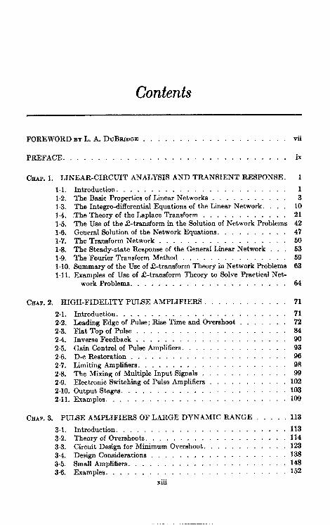
Contents
FOREWORD BY L. A. DUBRIDGE. . . . . . . . . . . . . . . . . . vii
PREFACE . . . . . . . . . . . . . . . . . . . . . . . . . . . . . . . ~
CrmP. 1. LINEAR-CIRCUIT ANALYSIS AND TRANSIENT RESPONSE. 1
1.1.1.2.1.3.1.4.1.5.1.6.1.7.1.8.1.9.1.10.1.11.
Introduction. . . . . . . . . . . . . . . . . . . . . .The Basic Propertiesof LinearNetworks . . .The Integro-differentialEquationsof the LinearNetwork. .The Theory of the LaplaceTransform . . . . . . . . .The Useof the $-transform in the Solutionof NetworkProblemsGeneralSolutionof the NetworkEquations. . .The TransformNetwork . . . . . . . . . . . . . . . . . .The Steady-stateResponseof the GeneralLinearNetwork .The FourierTransformMethod . . . . . . . .Summaryof the Useof C-transformTheory in NetworkProblemsExamplesof Use of ~-transform Theory to Solve PracticalNet-
13
1021424750535963
work Problems . . . . . . . . . . . . . . . . . . . . ..64
CHAP. 2. HIGH-FIDELITY PULSE AMPLIFIERS . . . . . 71
21.2.2.2.3.2.4.2.5.2.6.2.7.2.8.2.9.2.10.2.11.
Introduction . . . . . . . . . . . . . . . . . . . . . ...71Iieading Edge of Pulse; Rise Time and overshoot . 72Flat Topof Pulse . . . . . . . . . . . . . . . . . . ...84Inverse Feedback . . . . . . . . . . . . . . . . . . ...90Gain(%ntrol ofpulsehplifiers. . . 93D-cl%estoratio n . . . . . . . . . . . . . . . . . . ...96Limiting Amplifiers . . . . . . . . . . . . . . . . . . ...98The Mixing of Multiple Input SigDale . 99Electronic Switching of Pulse Amplifiers 102Output Stages . . . . . . . . . . . . . . . . . . . . ...103Examples . . . . . . . . . . . . . . . . . . . . . . ...109
CUP. 3. PULSE AMPLIFIERS OF LARGE DYNAMIC RANGE . . . 113
3.1. Introduction . . . . . . . . . . . . . . . . . . . . . . . . 1133.2. Theory of Overshoots. . . . . . . . . . . . . .1143.3. Circuit Design for Mirimum Overshoot. . . . . . . . 1233.4. Design Considerations . . . . . . . . . . . 1383.5. Small Amplifiers . . . . . . . . . . . . . . . . . . . ...1483.6. Examples . . . . . . . . . . . . . . . . . . . . . . ...152
...Xnl

xiv CONTENTS
CHAP. 4. SYNCHRONOUS AND STAGGERED SINGLE-TUNED HIGH-FREQUENCY BANDPASS AMPLIFIERS 166
4.1. Introduction. . . . . . . . . . . . . . . . . . . . . . . . 1664,2. One Single-tunedCircuit . 16s4.3. .kmplifierFiguresof Merit . 1714.4. CascadedSynchronousSingle-tunedCircuits, 1724.5. Exampleof a SynchronousSingle-tunedAmplifier 1744.6, Staggeredn-uples. ArithmeticSymmetry . . 1764.7. Staggeredmuples. GeometricSymmetry. 1804.8. Flat-etaggeredPairs,in Detaif, . . 1874.9. Flat-staggeredTriples,in Detail. . . 1894.10. Gain Controlof Stagger-tunedAmplifiers. . . 1914.11. Examplesof Stagger-tunedAmplifiers . . . . 192
CHAP. 5. DOUBLE-TUNED CIRCUITS. . . . . . 201
5,1. Introduction . . . . . . . . . . . . . . . . . . . . . . .,2015.2. The General Hlgh-QCaae. . . . . .2025.3. The High-( J,Equal-QCase. . . .2105.4. The High-Q Case When One of the Q’s Is Infinite . . . 21255. The Transitionally Coupled Low-Q Case , . 2165.6. Stagger-damped Double-tuned Circuits. . . . 2215,7. Construction and Examples. 226
CHAP. 6. HIGH-FREQUENCY FEEDBACK AMPLIFIERS. 232
6.1. Introduction . . . . . . . . . . . . . . . . . . . . . . ,. 23262. Analysis of the General Chain. . . 2356.3. The Inverse-feedback Pair 2416.4. Syntheeis of a Feedback Chain. . 2496.5. Miscellaneous Properties of Inverse-feedback Chains and Pairs 2536.6, Practical Considerations in Feedback-amplifier Design 2626.7. More Complicated Feedback Amplifiers. 2666,8. Practical Examples. .269
CHAP. 7. BANDPASS AMPLIFIERS: PULSE RESPONSE AND GENERALCONSIDERATIONS ..,..... . . . . . . . . . . . . ...274
PULSE RESPONSE . . . . . . . . . . . . . . . . . . . . . . . . .. 274
7.1. Reeponse of Bandpass Amplifier to Carrier-frequency Pulse 27472. One-poleN etworks . . . . . . . . . . . . 27773. Twe-poleN etworks . . . . . ., . . . . . . . . . . ...2787.4. Maximally Flat Three-pole Networks. . 2827.5. Maximally Flat -pole Networks. 2827.6. Gverstaggered Circuits . 284
GENERALConsiderations. . .287
7.7. Gain-bandwidth Factor. . . . 2877.8. Gain Contro l........ . . . . . . . . . . . . ...2907.9. Gain Variability....,.. . . . . . . . . . . . ...2917.10. Capacity Variability. . . . 2927.11. Pretuned Coils . . . . . . . . . . . 2957.12. Comparison of Amplifier Typea . 297

CONTENTS xv
CHAP. 8. AMPLIFIER MEASUREMENT AND TESTING . 301
81. Swept-frequency Signal Generators. 3018.2. Direct and Carrier-frequency Pulse Generators. 3068.3. Miscellaneous Testing Equipment . . . . 3138.4. Measurement and Alignment of Bandpass Amplifier. . . 3188.5. Undesired Feedback Effects (Regeneration) in Bandpass Ampli-
fiers . . . . . . . . . . . . . . . . . . . . . . . ...323
8.6. Pulse Response . . . . . . . . . . . . . . . . . . . ...3278,7. Overload and “Blackout” Effects . 3298& Measurement of Gain and Determination of .kmplifier Law 330
CHAP. 9. LOW-FREQUENCY AMPLIFIERS WITH STABILIZED GAIN 333
9.1. Problems Characteristic of Computer Amplifiers. 3339.2. Analysis of Types of Feedback. 33593. The Stability Problem. . . . .339
SAMPLEDESIGNe OF COMIWTER AMPLIFIERS . 347
9.4. Single-stage Drivers . . . . . . .3489,5. Driver with Push-pull Output Stage and Regeneration within the
Loop . . . . . . . . . . . . . . . . . . . . . . . ...350
TWO-STAGEDRIVER FOR INDUCTIVELOAD WITHOUT TRANSFORMER OUTPUT. 351
9.6. GeneraI Considerations. . 35197. Design of the Gutput Stage. 3529.8. Design of Pentode Stage. . . .3579.9. Constancy of Gain with Respect to Circuit Parameters. . 3619.10. Stability against Oscillation. . 363
THREE-STAGE AMPLIFIER FOR Rmmm LOAD. . 366
9.11. General Considerations. 3669.12. Design of Individual Stages. 367913. Stability against Low-frequency Oscillation 37o9.14. Stabilization against High-frequency Oscillation 3769,15. Experimental Checks and Completion of the Design . 382
CHAP. 10. LOW-FREQUENCY FEEDBACK AMPLIFIERS 384
10.1. Frequency-selective Networks. 38410.2. Frequency-selective Amplifiers. 39110.3. The Design of Frequency-selective Amplifiers 398
CHAP. 11. DIRECT-COUPLED AMPLIFIERS.
INTRODUCTION . . . . . . . . . . . .
11.1. Applications of Direct-coupled Amplifiers.11.2. Problems Peculiar to Direct-coupled Amplifiers
SPECIAL .4SPECTS AXD EFFECTS OF VACUUM-TURE PROPERTIES.
11.3. Variability of Vacuum-tube Characteristics11.4. Vacuum-tube Characteristics at Low Currents.11.5. Grid Current . . . . . .11.6. The Effect of Heater-voltage Variation.
,.. 409
,., 409
409. 411
. . . 412
412., 414-
.,. . -418
,.. . 421

xvi CONTENTS
DESIGN PRINCIPLES. . . . . . . . . . . . . . . . . . . . . . ...424
11.7. Single-ended Triode Amplifiers. 42411+3. Single-ended Pentode Amplifiers. 43211.9. Cascade and Other Series Amplifiers 4361110. Differential Amplifiers . 44111.11 . Output Circuits . . . . . . . . . . .. 45111.12. Cancellation of Effect of Heater-voltage Variation 4581113. The Use of Feedback in D-c.4mplifiers. 467
EXAMFLES OF SFECIAL-PUBPOSE AMPLIFIERS 479
11.14. Current-output Amplifiers. 4791115. Voltage-output Amplifiers. 48311.16. A Galvanometer-photoelectric Tube Feedback Amplifier . 48711.17 .D-c Amplifier Analysis. .491
C%IAP.12. AMpLIFIER SENSITIVITY. . 496
12.1. Introduction . . . . . . . . . . . . . 49612.2. Thermal Noise . . . . . . . . . . . . . . . . . . . . ...49712.3. Shot Noise . . . . . . . . . . . . . . . . . . . . . ...54412.4. The Logical Dktinction betweenThermalNoise and Shot Noise. 58412.5. OtherTypes of Tube Noise. .58812.6. OtherTypes of Input-circuitNoise. 595U&i. Amplifier Sensitivity: Definition and Theoretical Discussion of
Noise Figure, Available Power Gain, and Noise Temperature 59612G Amplifier sensitivity: Methods of Improvement by the Suppression
of Tube Noise . . . . . . . . . .604
CHAP. 13. MINIMAL NOISE CIRCUITS 615
13.1. Introduction . . . . . . . . . . . . . . .. 61513,2. Basic Noise-figure Considerations 61813.3. The Determination of the Noise Figlme, Power Gain, and Other
Characteristics of the First Stage. 62113,4. The Equivalent Noise Resistance of Practical Tubes . . 63513.5. The First-stage Noise Figure . 63813.6. The Optimum Source Admittance . 63913.7. Variation of Noise Figure with Source Conductance and with
Frequency . . . . . . . . . . ., ...,.,,....641138. Comparison of Alternative Tube Configurations . 64313.9. Noise Figures of Single-triode Input Circuits 65113.10. Double-triode Input Circuits 6561311. General Considerations of the Effect of Feedback on Noise Figure 66613.12. Miscellaneous Types of Feedback and Their Effect on Noise
Figure . . . . . . . . . . . . . . . . . . . . . . ...67213.13. The Correlation between the Induced Grid-noise and the Shot-
noise Currents . . . . . . . . . . . . . . . . . . . . . 67713.14. Input Coupling Networks. 68213.15. Example of Alternative Designs of Input Coupling Network 692
CEULP.1!2. MEASUREMENT OF NOISE FIGURE. . 695~&l. Introduction, ,,, .,... . . . . . . . . . . . . ...695l&.2. Discussion of Available Power, 697

CONTENTS xvii
14.3. Measurement of Noise Figure with Unmodulated Signal Gener-ators. The Relation of Noise Figure to Other Quantities ThatExpress the “ Noisinese” of an Amplifier 699
NOISE GENERATORS. . . . . . . . . . . . . . . . . . . . . . . .,700
14.4. General Discussion . . . . . .700145, Theory of Noise Generators Using Temperature-limited Diodes 70114.6. Construction of Diode Noise Generators 70414,7. Crystal Noise Generators, 70s
MEASUREMENTOF AMPLIFIEROUTFUTPOWER 708
14.8. Attenuator and Postamplifier 70914.9. Method Employing Gain-control or Uncalibrated Attenuator 71414.10, Crystal and Diode Rectifiers. . 71514.11 .Bolometers ..,.,.. . .. 715i4.12. Thermocouple Meters 717
SFECIALTOPICS, .,...... . . . . . . . . . . . . ,. 717
14.13. Effect of the Gain Control 71714,14. Correction for Temperature. 71714.15. Noise Figure of an Amplifier with Push-pull Input Connections 71914.16. Measurement of Noise Figure of Superheterodyne Radio Receiver
with Image Response. .720
APPENDIX A. REALIZABILITY OF FILTERS. . . 721
Al, The Paley-Wiener Criterion. . 721A2.Examples., ,,, ..,, . . . . . . . . . . . 723A.3. The Practicaf Meaning of the Paley-Wiener Criterion 726
APPENDIX B. CALCULATION OF LOAD-TUNING CONDENSER 728
APPENDIX C. DRIFT OF VACUUM-TUBE CHARACTERISTICSUNDER CONSTANT APPLIED POTENTIALS 730
INDEX . . . . . . . . . . . . . . . . . . . . . . . . . . . . . . . .735


![Finale 2002 - [15-1749H Spiritual Jubilee (SATB).MUS] · SATB Chorus and Piano* Bass Brightly q = 112 1. 6 down by the riv - er-side, doom doom doom doom doom ... We are climb - ing,](https://static.fdocuments.us/doc/165x107/5b2410317f8b9a9a028b5148/finale-2002-15-1749h-spiritual-jubilee-satbmus-satb-chorus-and-piano.jpg)