
INDEX OF SHEETS -...
36
Transcript of INDEX OF SHEETS -...


DateSheets RevisedRev. No.
TABLE OF REVISIONS
Sheet No.
INDEX OF SHEETS
Description
Estimated quantities and index of sheets
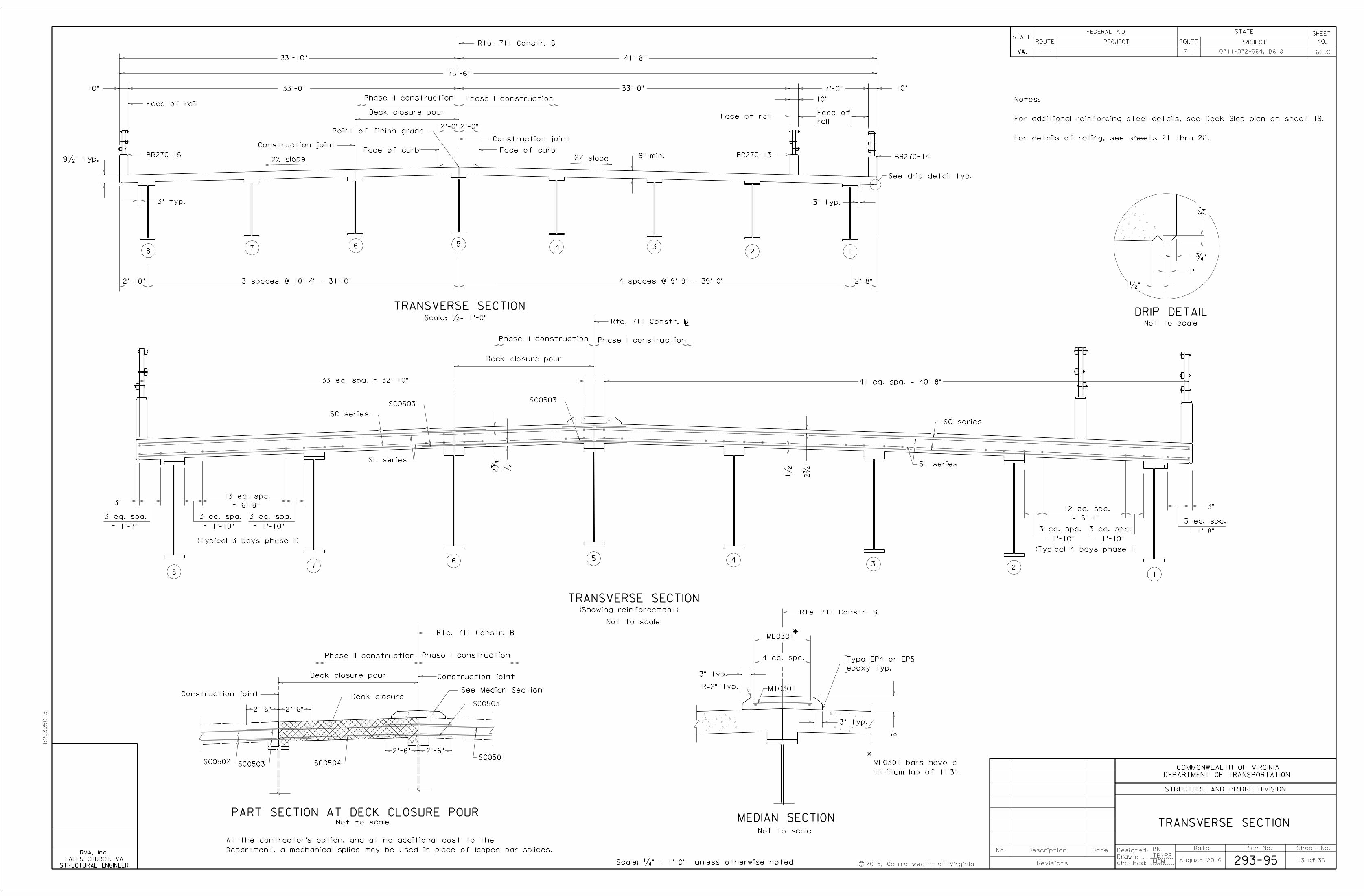
Transverse section
1
2
3
4
5
6
7
8
Title sheet: Plan, profile and general notes
No.
LUMP SUM BID ITEMS
Mobilization
Construction Surveying
LS
LS
LS
2
LS
Footing
Neat
Abutment A
Abutment B
Footing
Neat
Total
LBLB CY
Excav.
Struct.
ESTIMATED QUANTITIES - SUBSTRUCTURE ONLY
Units Quantity
CY
LB
LF
ESTIMATED QUANTITIES - SUPERSTRUCTURE ONLY
accordance with current Road and Bridge Specifications.
Denotes items to be paid for on the basis of plan quantities in
Item
Bridge Deck Grooving SY
Concrete Class A4 Bridge Appr. Slab
Reinf. Steel Bridge Approach Slab
CY
LB
Railing, BR27C 3 Rail
LF LF
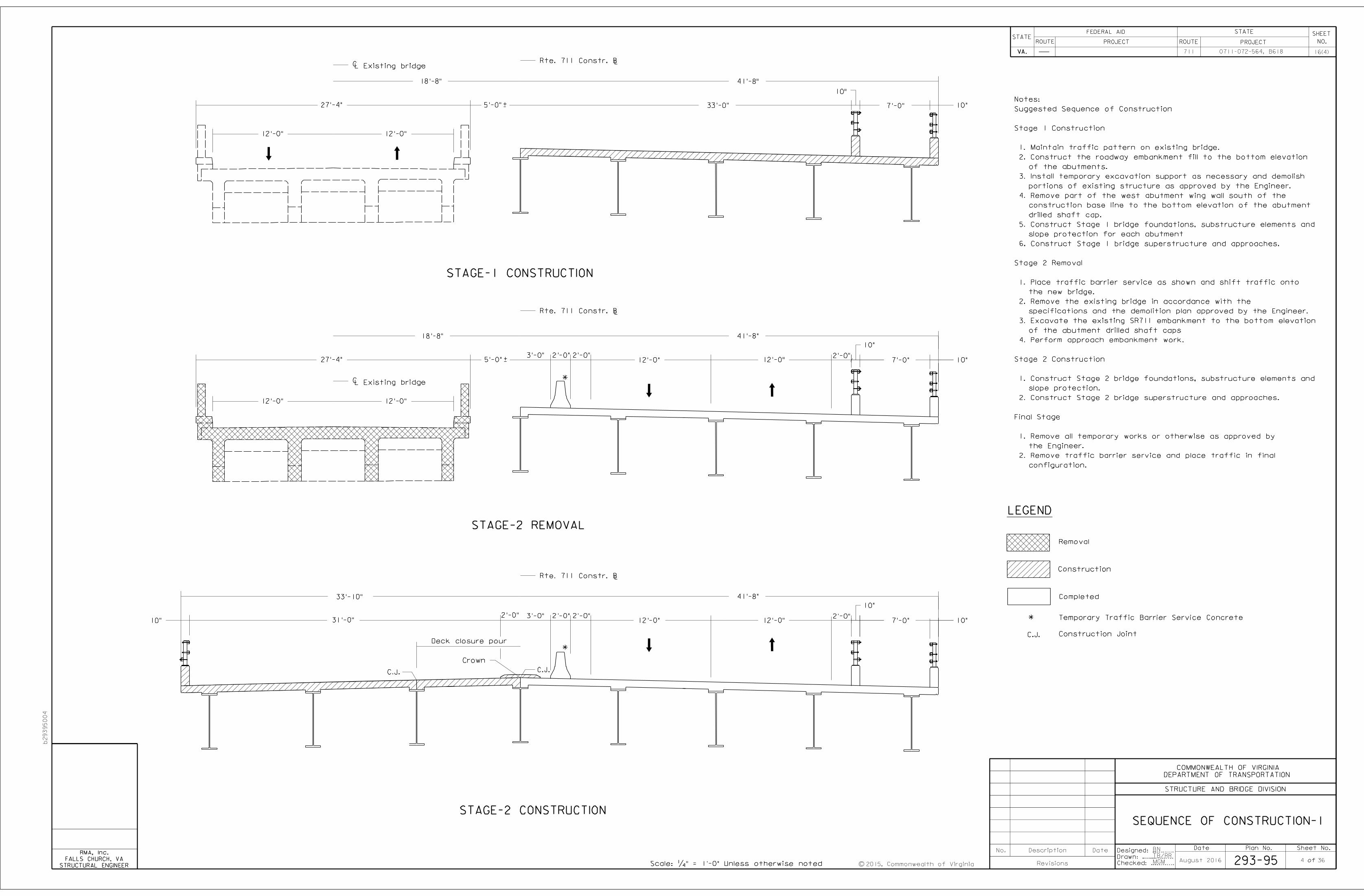
Sequence of construction - 1
LFRailing, BR27C 4 Rail
Abutment A plan and elevation
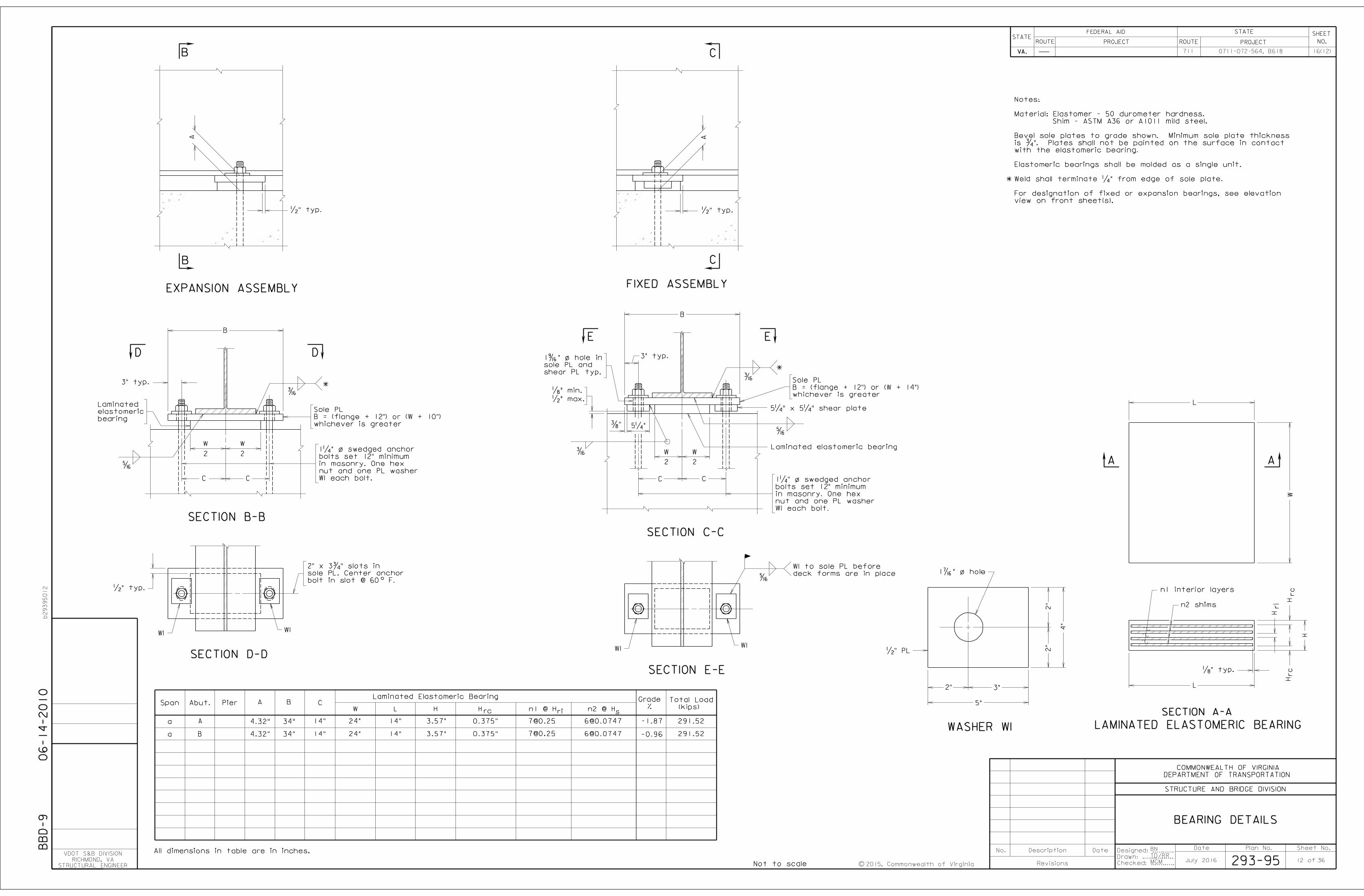
Bearing details
Plate girder details
9
10
11
12
13
14
15
16
17
18
19
20
21
22
23
25
26
27
28
54" BR27C-15 steel railing
54" BR27C-13 steel railing
54" BR27C-14 steel railing
Reinforcing steel schedule-substructure-1
Reinforcing steel schedule-substructure-2
Reinforcing steel schedule-superstructure
Sequence of construction - 2
30
Drilled shaft details
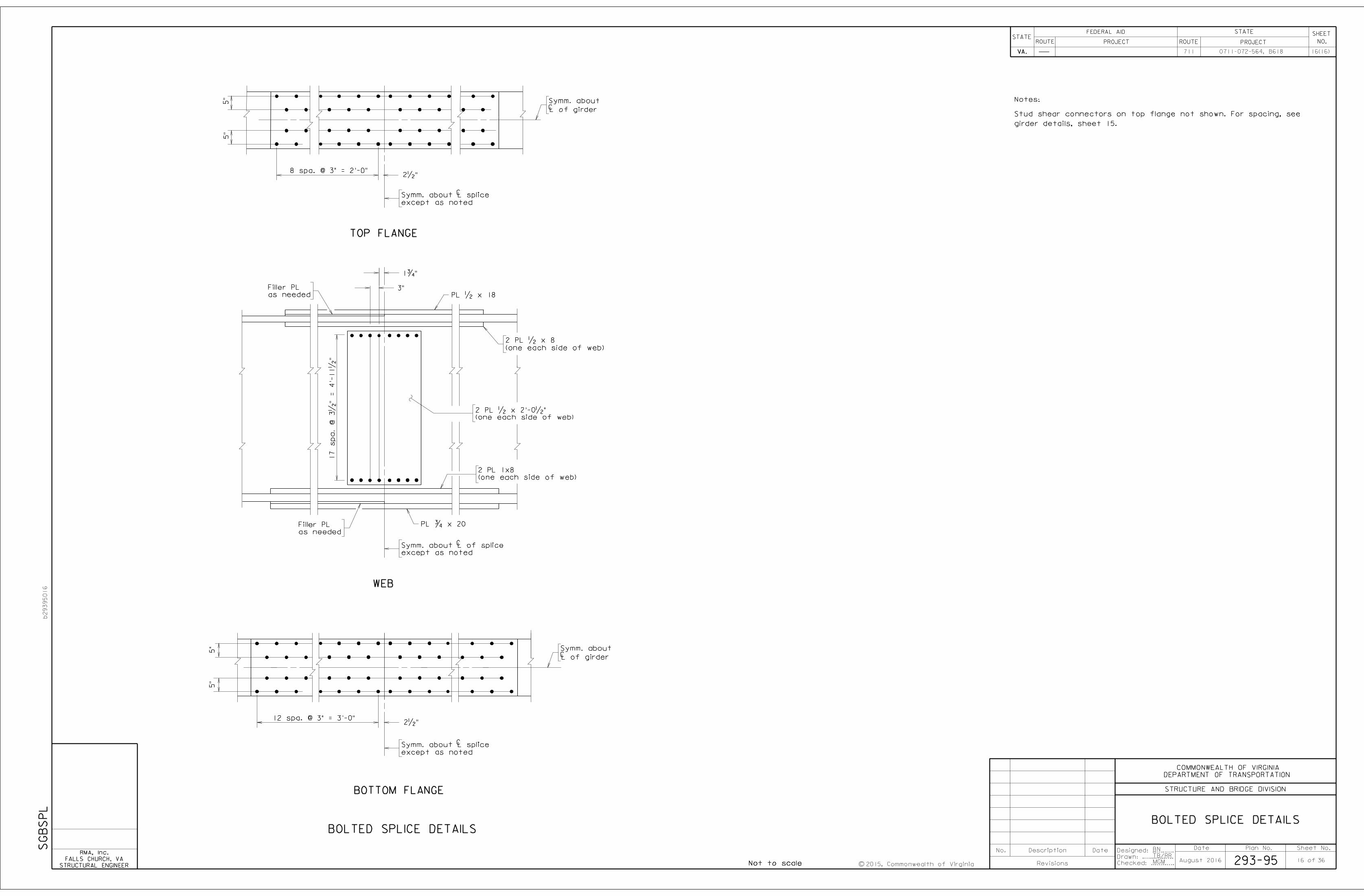
Bolted splice details
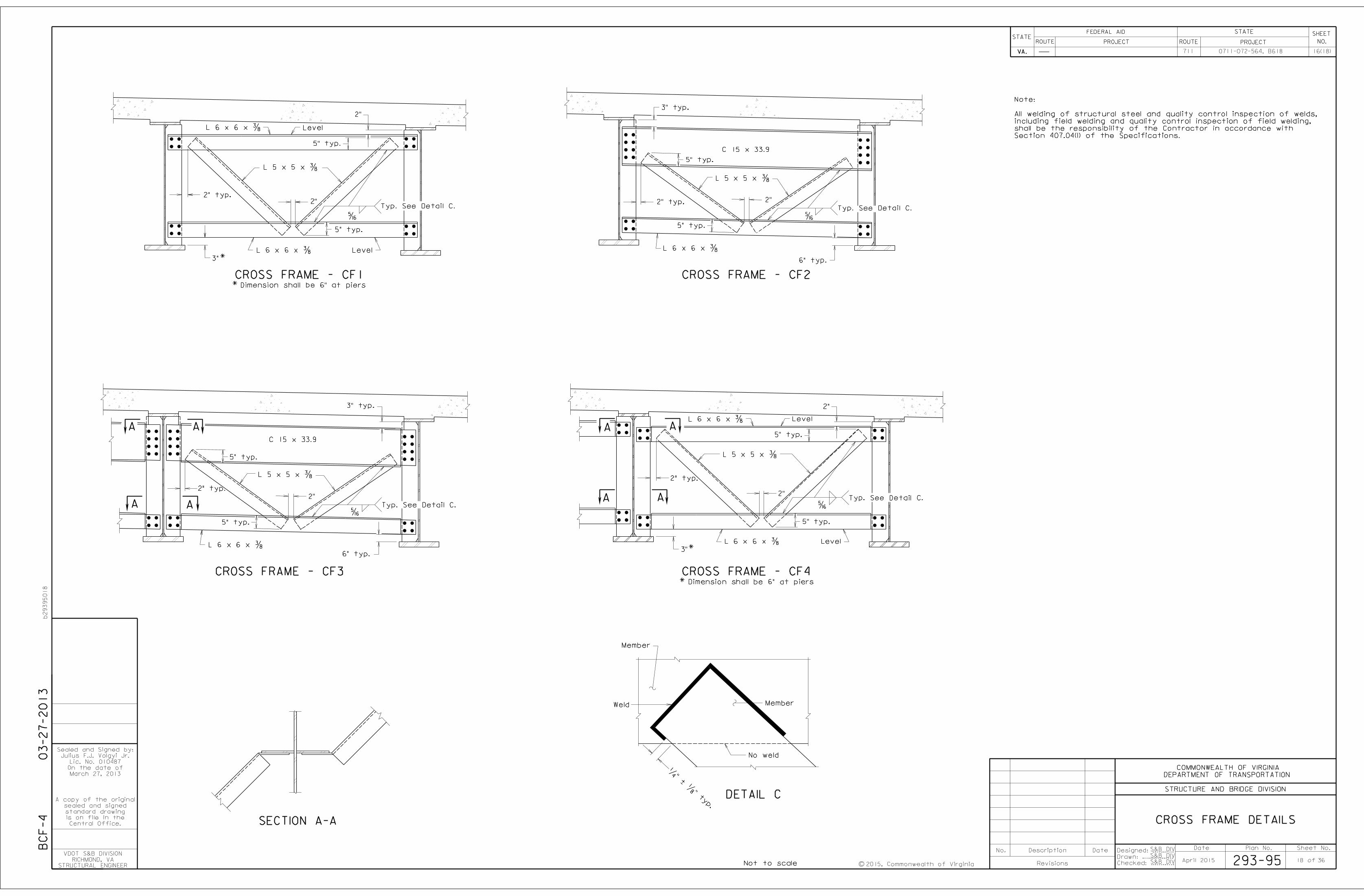
Cross frame details
ASTM 709 Grade 50W
Structural Steel Plate Girder LB
GENERAL NOTES (CONTINUED):
b29395002
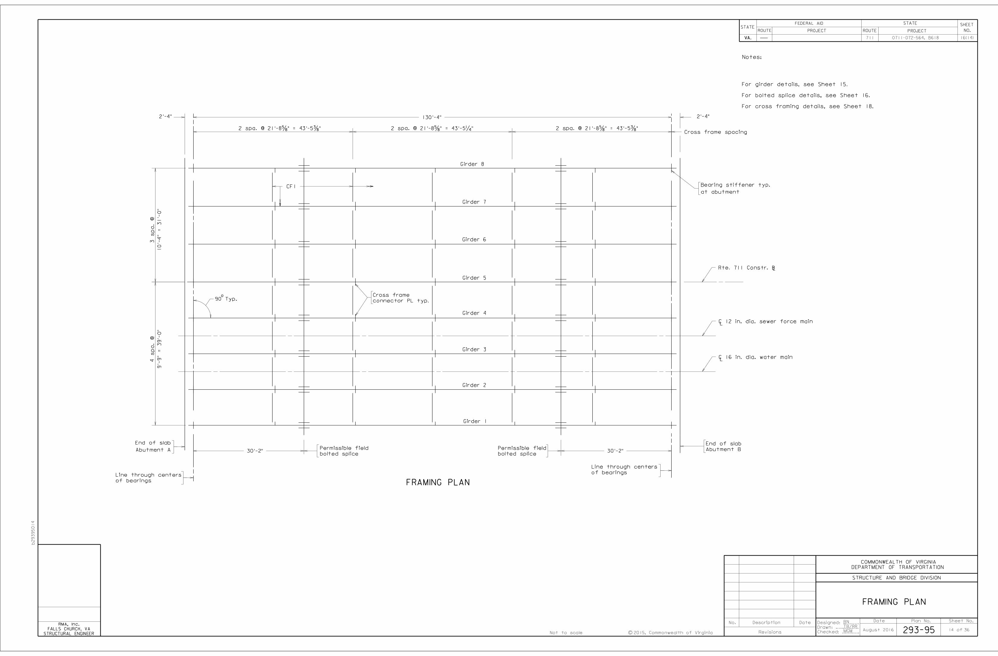
Framing plan
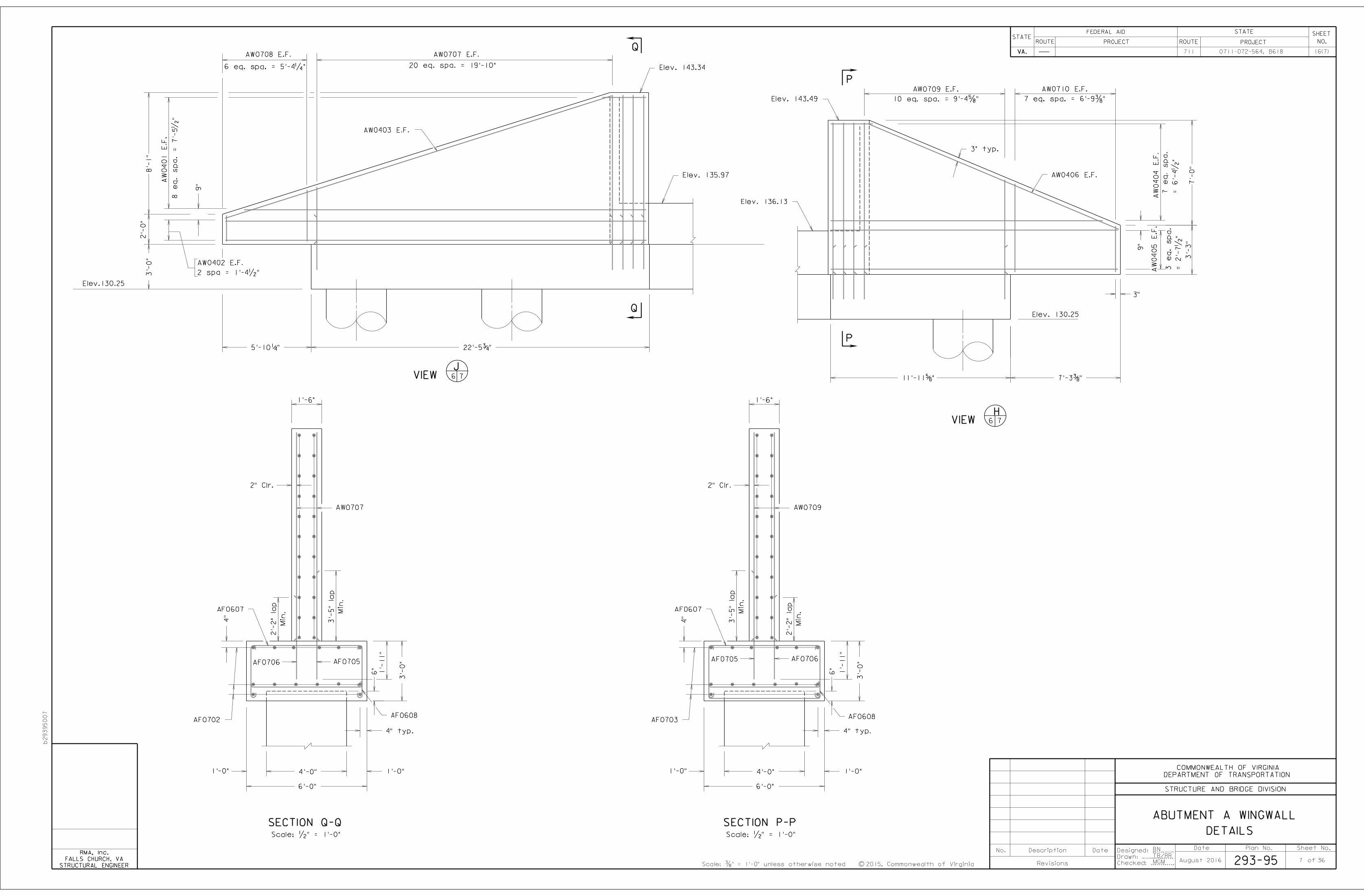
Abutment A wingwall details
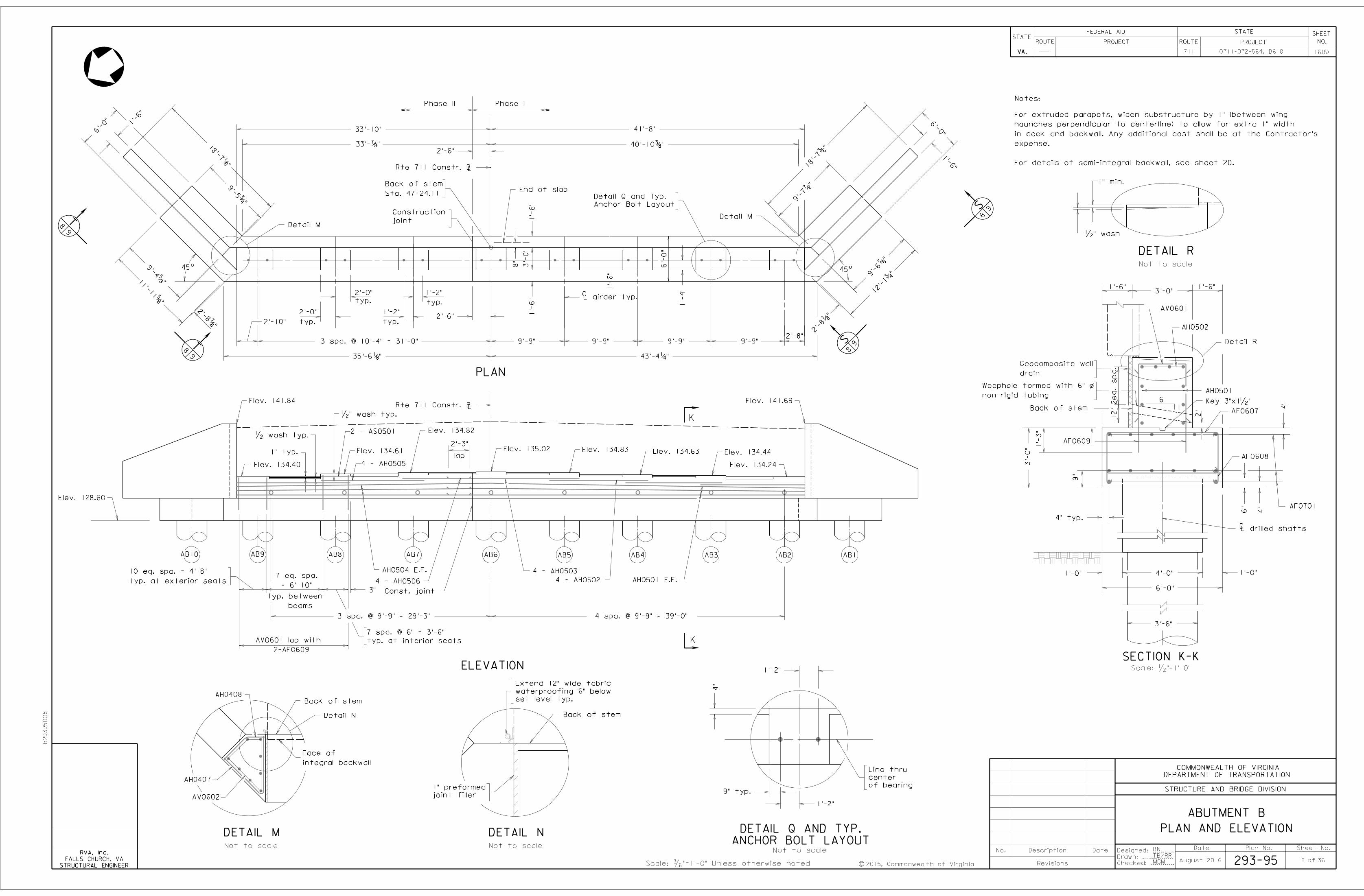
Abutment B plan and elevation
Abutment B wingwall details
Semi-Integral backwall plan and elevation
Abutment A and B footing plans
48"
Drilled Shaft
Stand. Excav.
Bridge Subs
NS Bridge Subs.
Bridge drainage details
29
*
*
BM "B": Square Set on the Top of Curb at the end of the
Median Island on the south side of State Route 711 on the
Rte. 711 Survey Baseline at PI 25+74.85 (Elevation 160.69’)
73
66
9,350
8,478
17,828
4,363
4,245
8,608 600
402
403
141
204
63
168
354
85,954
276
175
391,205
1,341
189
26,576
LS
SF
SY
362
765
CY
Class A4
Concrete
51
49
239
SYTONS
1850
2136
Temp. Excavation Support
NS Bridge Structure
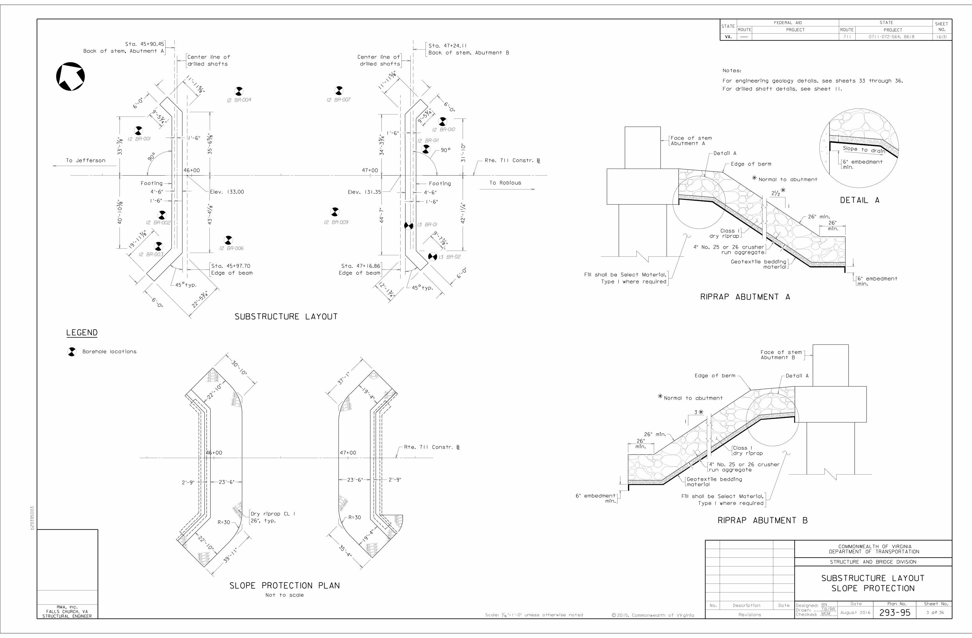
Substructure layout and slope protection
INDEX OF SHEETS
ESTIMATED QUANTITIES
24
Approach slabs
32
31
substituted for Class II.
Class I. Corrosion Resistant Reinforcing Steel, Class III, may be
Resistant Reinforcing, Class II or Class III, may be substituted for
plan sheets and in the reinforcing steel schedule. Corrosion
Class(es) of CRR steel(s) required on this project is/are noted on
steel and 60 ksi for stainless clad steel or solid stainless steel. The
minimum yield strength shall be: 100 ksi for low carbon/chromium
more of the three Classes listed in the special provision. The
Corrosion resistant reinforcing (CRR) steels shall conform to one or
Engineering geology-I
Engineering geology-2
Engineering geology-4
LF EA
2222
11
22
Testing
Logging (CSL)
Crosshole Sonic
Bridge Subs.
NS Bridge Subs.
Steel
Reinforcing
Drilled Shaft
Bridge Subs.
NS Bridge Subs.
LB
Thickness
18"
Inclusion
Elastic
42"
Rock Socket
Bridge Subs.
NS Bridge Subs.
Steel
Reinf.
26"
class I
Riprap
Dry
LF
55
20
75
88
80
42"
Drilled Shaft
Special Excav.
Bridge Subs.
NS Bridge Subs.
42-in. Rock Socket)
Drilled Shaft and
Shaft (48-in. dia.
Bridge Subs. Trial
NS Bridge Subs.
47
47
94
CBR-30
Min.
Type I
Matl.
Select
198
43,426
27,469
70,895 3,986
For drilled shaft notes, see sheet 11.
Engineering geology-3
Sealer 3�"
Preformed Elastomeric JointLF 148
Class II
Corrosion Resistant Reinforcing Steel
Class I
Steel
Reinforcing
Resistant
Corrosion
Structure (B618)
Dismantle and Remove Existing
ESTIMATED QUANTITIES NOTES:
accordance with current Road and Bridge Specifications.
Denotes items to be paid for on the basis of plan quantities in
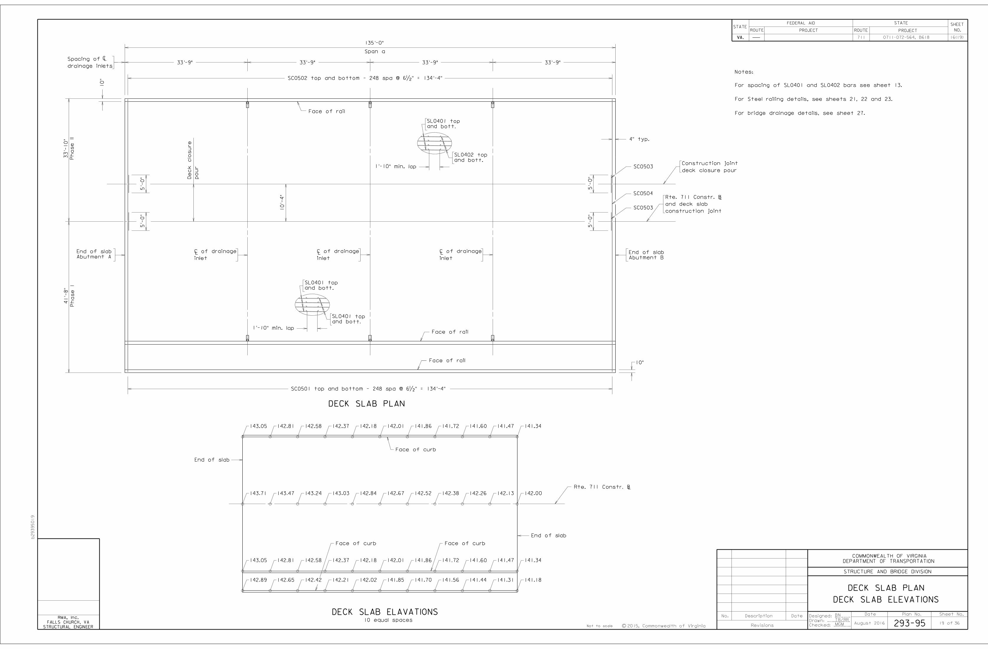
Deck slab plan and deck slab elevations
Lump Sum
Dead load deflections and slab elevations
of Virginia and get them approved by the COTR.
and shop drawings prepared by a professional engineer certified by the Commonwealth
work on temp. excavation support is begun, the contractor shall submit the design
construction for temp. excavation support and incidentals thereof. Before any
Item NS Bridge Structure Temp. Excavation Support includes all phases of
piling that will interfere with the new construction.
remain in place. Also, removal shall include any part of the substructure or foundation
at least 3 feet below the natural ground or finished grade of embankment that is to
Abutment B, as a minimum, the substructure shall be removed to an elevation of
the substructure shall be removed down to the top of the existing footing. For
superstructure, substructure, and slope protection. For Abutment A, as a minimum,
Dismantling and removing existing structure shall include removing the entire
33
BR27C-16 rail connection and notes
54" BR27C/BR27D terminal wall on abutment
54" BR27C/BR27D terminal wall on approach slab
34
35
Deck Drainage System - B618 LS
36 Approach slab details
40
STP5A27(207)
Bridge No. of existing bridge is 6024, Plan No. is 87-19.
SY
Wall Drain
Composite
Geo
27
27
54
*
Concrete Class A4 *
*
pipe supports and splash blocks.
shall include drainage assemblies, drain pipes,
Bid item Deck Drainage System - B618
16(2)
*Remove Existing Asbestos (B618)
11
Concrete Class A4 shall be Modified Low Shrinkage Concrete
The quantity also includes for the median.
Bid item bridge deck grooving includes the quantity for approach slabs.
Date Plan No. Sheet No.Designed: ...........
Drawn: ................
Checked: ............2015, Commonwealth of Virginiac
No. Description Date
STRUCTURE AND BRIDGE DIVISION
COMMONWEALTH OF VIRGINIA
DEPARTMENT OF TRANSPORTATION
Revisions
ROUTE
FEDERAL AID
PROJECT ROUTE PROJECT
STATE SHEET
NO.
VA.
STATEROUTE
FEDERAL AID
PROJECT ROUTE PROJECT
STATE SHEET
NO.
VA.
STATE
STRUCTURAL ENGINEER
FALLS CHURCH, VA
RMA, Inc.BN
TB/RR
MGM 36of
711 0711-072-564, B618
293-95August 2016


![Chemical characterisation of humic-like substances from ...salma.web.elte.hu/pubs/EnvironChem9_2012_273.pdfstructural properties to terrestrial and aquatic humic and fulvic acids.[1,4]](https://static.fdocuments.us/doc/165x107/6103e565e083b042d95647cc/chemical-characterisation-of-humic-like-substances-from-salmawebeltehupubsenvironchem92012273pdf.jpg)


