INDEX July, 2003 THM 4L30-Eshop.ukrtrans.biz/wp-content/uploads/catalogs/4L30E.pdfthm 4l30-e...
120
INDEX THM 4L30-E AUTOMATIC TRANSMISSION SERVICE GROUP 18639 SW 107TH AVENUE MIAMI, FLORIDA 33157 (305) 670-4161 "Portions of materials contained herein have been reprinted under license from General Motors Corp, Service & Parts Operations." The information and part numbers contained in this booklet have been carefully compiled from industry sources known for their reliability, but ATSG does not guarantee its accuracy. Copyright © ATSG 1992 Updated July, 2003 2 POWER FLOW CHART AND SOLENOID APPLICATION ............................ 3 ELECTRONIC OPERATION .......................................................................... 4 FAIL-SAFE MODE ......................................................................................... 5 SOLENOID SPECIFICATIONS ...................................................................... 10 LINE PRESSURE CHECK .............................................................................. 11 CONNECTOR LOCATIONS ........................................................................... 12 VEHICLE WIRING SCHEMATIC .................................................................... 14 TRANSMISSION DISASSEMBLY .................................................................. 16 COMPONENT REBUILD ............................................................................... 34 VALVE BODY CHECKBALL LOCATION ...................................................... 51 TRANSMISSION ASSEMBLY ........................................................................ 54 INDEXING PLANETARY GEARS .................................................................. 57 MAIN CASE CHECK BALL LOCATIONS ...................................................... 70 ADAPTER CASE CHECKBALL LOCATION ................................................. 74 TORQUE SPECIFICATIONS .......................................................................... 77 ELECTRONIC QUICK CHECKS .................................................................... 78 ELECTRICAL TESTS .................................................................................... 80 TROUBLE CODE CHART ............................................................................. 103 SPECIAL TOOL LIST .................................................................................... 105 RETRIEVING TROUBLE CODES ................................................................. 109
Transcript of INDEX July, 2003 THM 4L30-Eshop.ukrtrans.biz/wp-content/uploads/catalogs/4L30E.pdfthm 4l30-e...

INDEXTHM 4L30-E
AUTOMATIC TRANSMISSION SERVICE GROUP18639 SW 107TH AVENUEMIAMI, FLORIDA 33157
(305) 670-4161
"Portions of materials contained herein have been reprinted underlicense from General Motors Corp, Service & Parts Operations."
The information and part numbers contained in this booklet havebeen carefully compiled from industry sources known for their
reliability, but ATSG does not guarantee its accuracy.Copyright © ATSG 1992
UpdatedJuly, 2003
2
POWER FLOW CHART AND SOLENOID APPLICATION ............................ 3
ELECTRONIC OPERATION .......................................................................... 4
FAIL-SAFE MODE ......................................................................................... 5
SOLENOID SPECIFICATIONS ...................................................................... 10
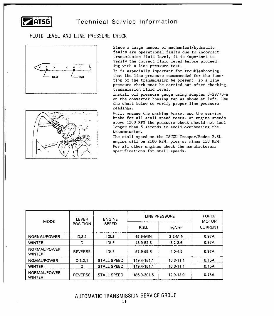
LINE PRESSURE CHECK .............................................................................. 11
CONNECTOR LOCATIONS ........................................................................... 12
VEHICLE WIRING SCHEMATIC .................................................................... 14
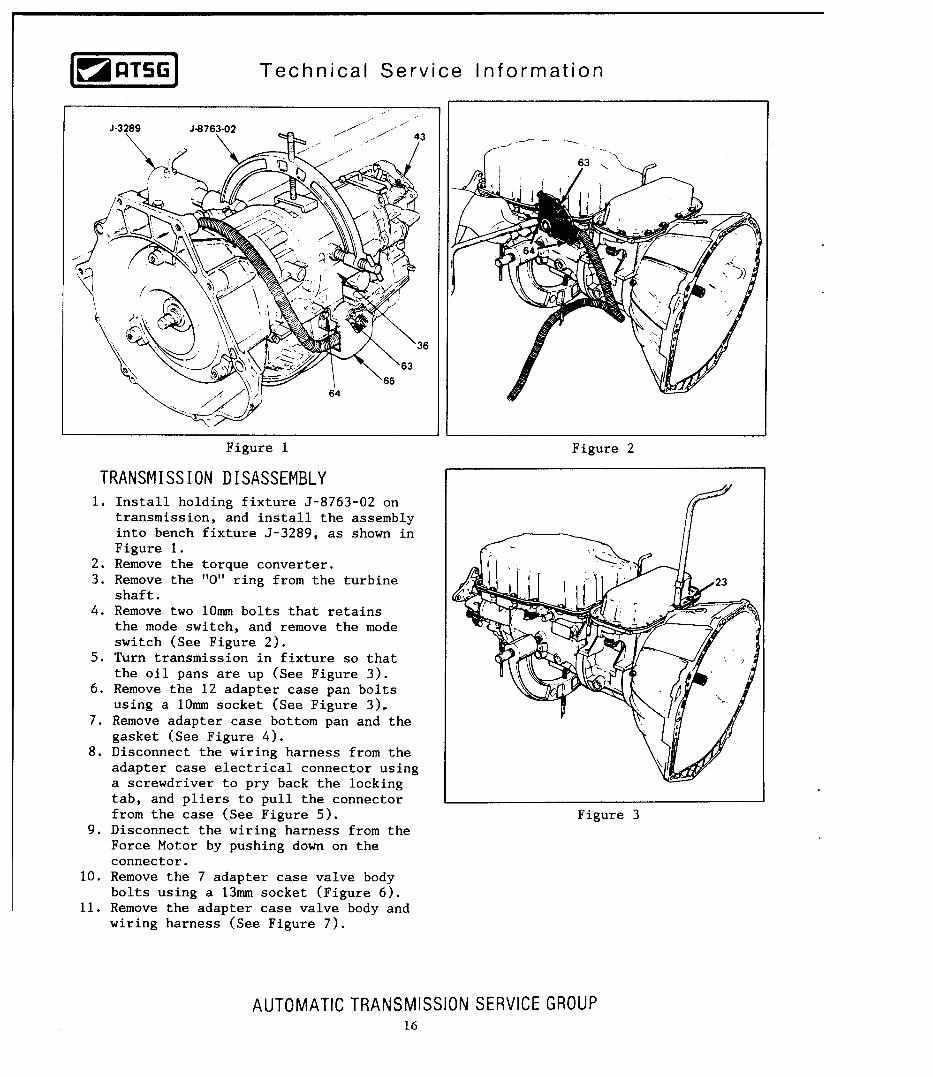
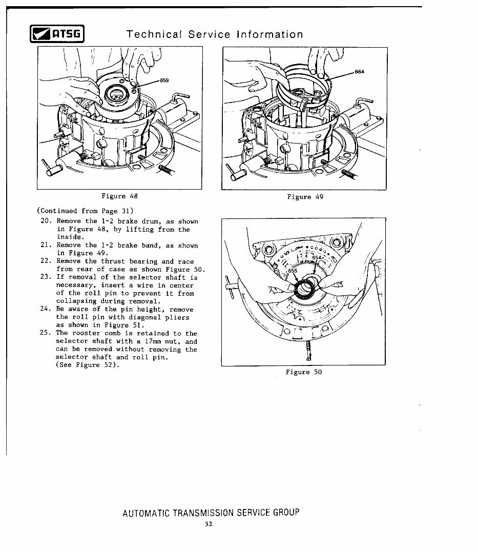
TRANSMISSION DISASSEMBLY .................................................................. 16
COMPONENT REBUILD ............................................................................... 34
VALVE BODY CHECKBALL LOCATION ...................................................... 51
TRANSMISSION ASSEMBLY ........................................................................ 54
INDEXING PLANETARY GEARS .................................................................. 57
MAIN CASE CHECK BALL LOCATIONS ...................................................... 70
ADAPTER CASE CHECKBALL LOCATION ................................................. 74
TORQUE SPECIFICATIONS .......................................................................... 77
ELECTRONIC QUICK CHECKS .................................................................... 78
ELECTRICAL TESTS .................................................................................... 80
TROUBLE CODE CHART ............................................................................. 103
SPECIAL TOOL LIST .................................................................................... 105
RETRIEVING TROUBLE CODES ................................................................. 109

INTRODUCTIONTHM 4L30-E
AUTOMATIC TRANSMISSION SERVICE GROUP18639 SW 107TH AVENUEMIAMI, FLORIDA 33157
(305) 670-4161
DALE ENGLANDFIELD SERVICE CONSULTANT
ED KRUSETECHNICAL CONSULTANT
WAYNE COLONNATECHNICAL SUPERVISOR
PETER LUBANTECHNICAL CONSULTANT
JIM DIALTECHNICAL CONSULTANT
GREGORY LIPNICKTECHNICAL CONSULTANT
JERRY GOTTTECHNICAL CONSULTANT
JON GLATSTEINTECHNICAL CONSULTANT
DAVID CHALKERTECHNICAL CONSULTANT
MIKE SOUZATECHNICAL CONSULTANT
ROLAND ALVAREZTECHNICAL CONSULTANT
GERALD CAMPBELLTECHNICAL CONSULTANT
No part of any ATSG publication may be reproduced, stored in any retrieval system or transmitted in any form or by any means, including but not limited to electronic, mechanical, photocopying, recording or otherwise, without written permission of Automatic Transmission Service Group. This includes all text illustrations, tables and charts.
"Portions of materials contained herein have been reprinted underlicense from General Motors Corp, Service & Parts Operations."
The information and part numbers contained in this booklet havebeen carefully compiled from industry sources known for their
reliability, but ATSG does not guarantee its accuracy.
Copyright © ATSG 1992
UpdatedJuly, 2003
1
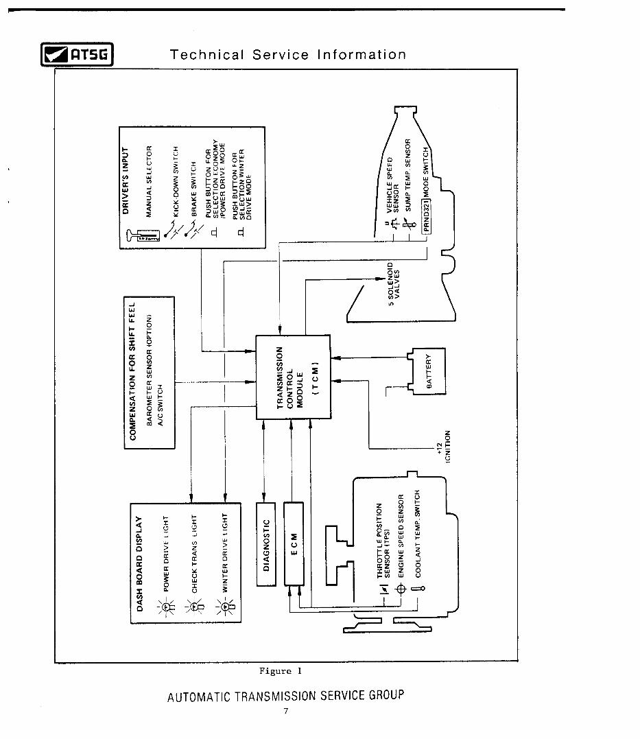
This booklet contains the general description and the procedures necessary to repair, overhaul, or service the Hydra-matic 4L30-E transmission that is currently found in the Opel Omega, Opel Senator, BMW, and the Isuzu Trooper/Rodeo. This transmission is a completely electronic controlled, 4 speed, rear wheel drive unit.
Gear ratios are as follows:Opel/BMW
2.401st Gear2nd Gear3rd Gear4th GearReverse
Trooper/Rodeo2.861.621.481.001.000.720.722.002.00


AUTOMATIC TRANSMISSION SERVICE GROUP
Technical Service Information
78
DATA LIST F0 QUICK CHECK

AUTOMATIC TRANSMISSION SERVICE GROUP
Technical Service Information
79
DATA LIST F0 QUICK CHECK

AUTOMATIC TRANSMISSION SERVICE GROUP
Technical Service Information
80
ELECTRICAL TESTS

AUTOMATIC TRANSMISSION SERVICE GROUP
Technical Service Information
81

AUTOMATIC TRANSMISSION SERVICE GROUP
Technical Service Information
82

AUTOMATIC TRANSMISSION SERVICE GROUP
Technical Service Information
83

AUTOMATIC TRANSMISSION SERVICE GROUP
Technical Service Information
84

AUTOMATIC TRANSMISSION SERVICE GROUP
Technical Service Information
85

AUTOMATIC TRANSMISSION SERVICE GROUP
Technical Service Information
86

AUTOMATIC TRANSMISSION SERVICE GROUP
Technical Service Information
87

AUTOMATIC TRANSMISSION SERVICE GROUP
Technical Service Information
88

AUTOMATIC TRANSMISSION SERVICE GROUP
Technical Service Information
89

AUTOMATIC TRANSMISSION SERVICE GROUP
Technical Service Information
90

AUTOMATIC TRANSMISSION SERVICE GROUP
Technical Service Information
91

AUTOMATIC TRANSMISSION SERVICE GROUP
Technical Service Information
92

AUTOMATIC TRANSMISSION SERVICE GROUP
Technical Service Information
93

AUTOMATIC TRANSMISSION SERVICE GROUP
Technical Service Information
94

AUTOMATIC TRANSMISSION SERVICE GROUP
Technical Service Information
95

AUTOMATIC TRANSMISSION SERVICE GROUP
Technical Service Information
96

AUTOMATIC TRANSMISSION SERVICE GROUP
Technical Service Information
97

AUTOMATIC TRANSMISSION SERVICE GROUP
Technical Service Information
98

AUTOMATIC TRANSMISSION SERVICE GROUP
Technical Service Information
99

AUTOMATIC TRANSMISSION SERVICE GROUP
Technical Service Information
100
AUTOMATIC TRANSMISSION SERVICE GROUP
Technical Service Information
101

AUTOMATIC TRANSMISSION SERVICE GROUP
Technical Service Information
102
AUTOMATIC TRANSMISSION SERVICE GROUP
Technical Service Information
103
TROUBLE CODE CHART

AUTOMATIC TRANSMISSION SERVICE GROUP
Technical Service Information
104
TROUBLE CODE CHART

AUTOMATIC TRANSMISSION SERVICE GROUP
Technical Service Information
105
TROUBLE CODE CHART

AUTOMATIC TRANSMISSION SERVICE GROUP
Technical Service Information
106

AUTOMATIC TRANSMISSION SERVICE GROUP
Technical Service Information
107

AUTOMATIC TRANSMISSION SERVICE GROUP
Technical Service Information
108

AUTOMATIC TRANSMISSION SERVICE GROUP
Technical Service Information
109
DIAGNOSTIC TROUBLE CODE RETRIEVAL AND DEFINITIONFOR TROOPER, RODEO, ACURA SLX AND PASSPORT "ONLY"
THM 4L30-E
For Trouble code retrieval, locate Diagnostic 2 connector shown in Figure 2 (White for Trooper and Black for Rodeo). Jump the connector as shown in Figure 2 and refer to Figures 8-10 for code definitions. The "Check Trans" lamp flash patterns for normal operation, and when DTC's are set, are shown in Figure 1.
For Trouble code retrieval, locate Diagnostic 1 connector shown in Figure 3. Jump the connector between terminals 1 and 3, as shown in Figure 3 and refer to Figures 8-10 for code definitions. The "Check Trans" lamp flash patterns for normal operation, and when DTC's are set, are shown in Figure 1.
For Trouble code retrieval, locate Diagnostic 2 connector shown in Figure 4. Jump the connector as shown in Figure 4 and refer to Figures 11 and 12 for code definitions. The "Check Trans" lamp flash patterns for normal operation, and when DTC's are set, are shown in Figure 1.
For Trouble code retrieval, locate Diagnostic 2 connector shown in Figure 5. Jump the connector as shown in Figure 5 and refer to Figures 11 and 12 for code definitions. The "Check Trans" lamp flash patterns for normal operation, and when DTC's are set, are shown in Figure 1.
For Trouble code retrieval, locate the 16 pin OBD-II connector as shown in Figure 6. Connect a scan tool as this is the only way to retrieve trouble codes. Refer to Figures 13 and 14 for code definitions.The "Check Trans" lamp will be flashing if codes are stored in memory.
For Trouble code retrieval, locate the 16 pin OBD-II connector as shown in Figure 7. Connect a scan tool as this is the only way to retrieve trouble codes. Refer to Figures 13 and 14 for code definitions.The "Check Trans" lamp will be flashing if codes are stored in memory.
1990-1991 TROOPER AND 1991-1992 RODEO "ONLY"
1992-1993 TROOPER AND 1993 RODEO "ONLY"
1994 TROOPER, RODEO AND PASSPORT "ONLY"
1995 TROOPER, RODEO AND PASSPORT "ONLY"
1996-1997 TROOPER AND ACURA SLX "ONLY"
1996-1997 RODEO AND PASSPORT "ONLY"

AUTOMATIC TRANSMISSION SERVICE GROUP
Technical Service Information
110
ON
OFF
3.2 Sec
0.4 Sec 0.4 Sec 0.4 Sec 0.4 Sec
0.4 Sec 0.4 Sec0.4 Sec 0.4 Sec
ON
OFF
3.0 Sec. (SOHC)2.0 Sec. (DOHC)LAMP CHECK
ON
OFF
3.2 Sec 1.2 Sec 1.2 Sec
0.4 Sec
0.4 Sec 0.4 Sec
0.4 Sec0.4 Sec 0.4 Sec
DTC 11 DTC 32
CONTINUOUS EVEN FLASH = "NO CODES"
CHECKTRANSCHECKTRANS
CHECKTRANSCHECKTRANS
EACH DIAGNOSTIC TROUBLE CODE WILL REPEAT 3 TIMES IN NUMERICAL ORDER
NOTE:
STEP 1
STEP 2
ON
OFF
3.0 Sec. (SOHC)2.0 Sec. (DOHC)LAMP CHECK
IGNITION KEY ON
IGNITION KEY ON
0.2 Sec.
0.2 Sec.
"NORMAL" CHECK TRANS LIGHT OPERATION
CHECK TRANS LIGHT OPERATION"WHEN DTC'S ARE SET"
NOTE: A DTC 12 (NO DITRIBUTOR REFERENCE) IS NORMAL IF TROUBLE CODES ARE ACCESSED WITH THE ENGINE "OFF".
CONNECT JUMPER WIRE TO DIAGNOSTICCONNECTOR FOR YOUR VEHICLE APPLICATION.
"CHECK TRANS" LIGHT WILL FLASH AS FOLLOWS:
Figure 1

AUTOMATIC TRANSMISSION SERVICE GROUP
Technical Service Information
111
90-91 TROOPER AND 91-92 RODEO "ONLY"
92-93 TROOPER AND 93 RODEO "ONLY"
1 2 3
DIAGNOSTIC 1CONNECTOR
(TECH-1 USE ONLY)
21
DIAGNOSTIC 2CONNECTOR
1 2 3
DIAGNOSTIC 1CONNECTOR
JUMP TERMINALS 1 & 2 OF DIAGNOSTIC 2CONNECTOR FOR CODE RETRIEVAL
"White" Connector on Trooper"Black" Connector on Rodeo
JUMP TERMINALS 1 & 3 OF DIAGNOSTIC 1CONNECTOR FOR CODE RETRIEVAL
REPOROT
OEDOR
TERMINAL WIRE COLOR
1 YEL/BLK
BLACK2
DIAGNOSTIC 2 WIRE COLORS
TERMINAL WIRE COLOR
1 YELLOW/BLACK
BLACK/GREEN
WHT/RED (92) WHT/GRN (93)2
3
"TROOPER" DIAGNOSTIC 1 WIRE COLORS
TERMINAL WIRE COLOR
1 YELLOW/BLACK
BLACK
WHITE/RED 2
3
"RODEO" DIAGNOSTIC 1 WIRE COLORS
DIAGNOSTIC CONNECTOR LOCATION IS BY THE TCM FOR TROOPER, AND EITHER
BY THE TCM FOR RODEO, OR TAPED NEAR THE LEFT SPEAKER.
DIAGNOSTIC CONNECTOR LOCATION ISBEHIND THE CENTER CONSOLE ON TROOPER
AND BY THE TCM ON RODEO
Figure 2
Figure 3

94 TROOPER, RODEO AND PASSPORT "ONLY"
95 TROOPER, RODEO AND PASSPORT "ONLY"
1 2 3
DIAGNOSTIC 1CONNECTOR
(TECH-1 USE ONLY)
1 2 3
DIAGNOSTIC 1CONNECTOR
(TECH-1 USE ONLY)
JUMP TERMINALS 1 & 2 OF DIAGNOSTIC 2CONNECTOR FOR CODE RETRIEVAL
JUMP TERMINALS 1 & 2 OF DIAGNOSTIC 2CONNECTOR FOR CODE RETRIEVAL
DIAGNOSTIC CONNECTOR FORTROOPER, RODEO AND PASSPORT LOCATED BEHIND ACCESS DOOR
REPOORT
OEDOR
21
DIAGNOSTIC 2CONNECTOR
21
DIAGNOSTIC 2CONNECTOR
TERMINAL WIRE COLOR
1 YELLOW/BLACK
BLACK/GREEN2
TROOPER DIAGNOSTIC 2 WIRE COLORS
TERMINAL WIRE COLOR
1 YELLOW/BLACK
BLACK/ORANGE2
PASSPORT/RODEO DIAGNOSTIC 2 WIRE COLORS
TERMINAL WIRE COLOR
1 YELLOW/BLACK
BLACK/ORANGE2
TROOPER,PASSPORT AND RODEO DIAGNOSTIC 2 WIRE COLORS
DIAGNOSTIC CONNECTOR LOCATION IS BEHIND CONSOLE ON TROOPER AND
BY TCM ON PASSPORT AND RODEO
Figure 4
Figure 5
AUTOMATIC TRANSMISSION SERVICE GROUP
Technical Service Information
112

96 TROOPER AND ACURA SLX "ONLY"
96-97 RODEO AND PASSPORT "ONLY"
16-PIN OBD-II CONNECTOR
DIAGNOSTIC CONNECTOR FOR 1996 TROOPER AND ACURA SLX
LOCATED BEHIND ACCESS DOOR IN LEFT KICK PANEL
DIAGNOSTIC CONNECTOR FOR 1997 TROOPER AND ACURA SLX
LOCATED BEHIND ACCESS DOOR ON DASH IN FRONT OF LEFT KNEE
DIAGNOSTIC CONNECTOR FORRODEO AND PASSPORT LOCATED
UNDER DASH NEAR HOOD RELEASE
SCAN TOOL IS MANDATORYFOR CODE RETRIEVAL
SCAN TOOL IS MANDATORYFOR CODE RETRIEVAL
16-PIN OBD-II CONNECTOR
Figure 6
Figure 7
AUTOMATIC TRANSMISSION SERVICE GROUP
Technical Service Information
113
AUTOMATIC TRANSMISSION SERVICE GROUP
Technical Service Information
114
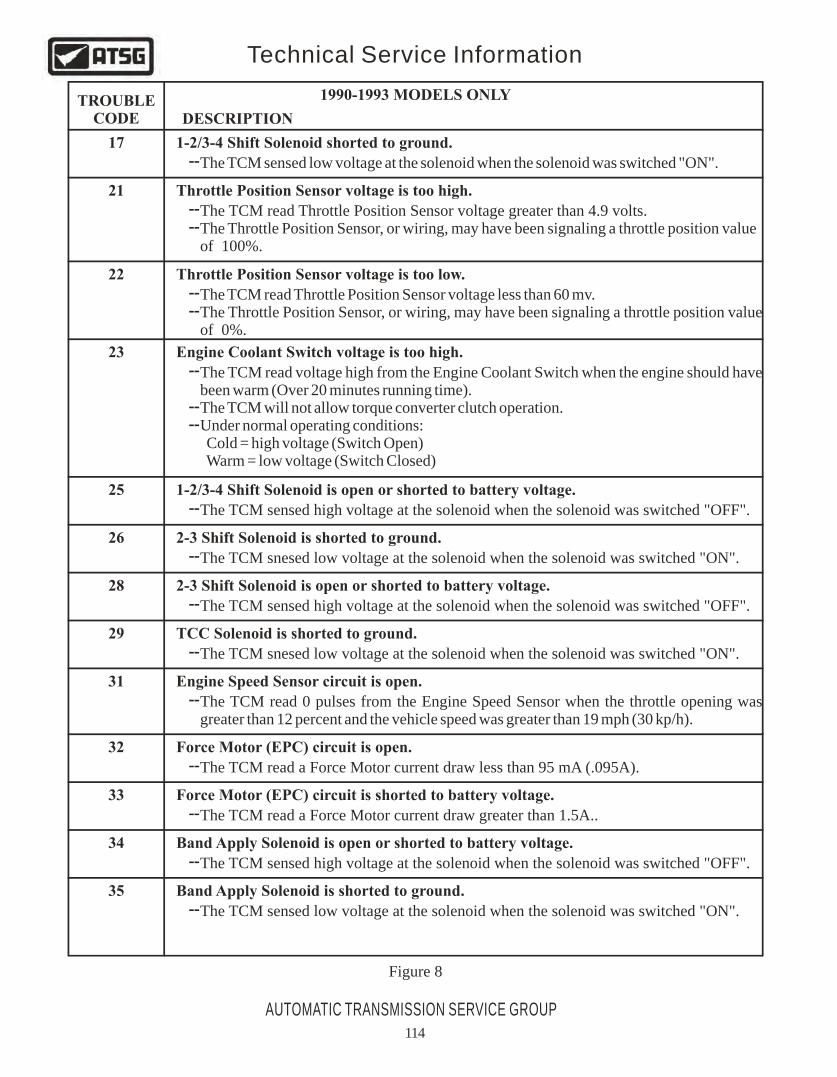
TROUBLECODE DESCRIPTION
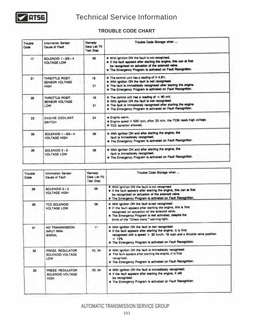
17
21
22
23
25
26
28
29
31
32
33
34
35
1-2/3-4 Shift Solenoid shorted to ground.
1-2/3-4 Shift Solenoid is open or shorted to battery voltage.
2-3 Shift Solenoid is open or shorted to battery voltage.
Band Apply Solenoid is open or shorted to battery voltage.
2-3 Shift Solenoid is shorted to ground.
TCC Solenoid is shorted to ground.
Band Apply Solenoid is shorted to ground.
Engine Speed Sensor circuit is open.
Force Motor (EPC) circuit is open.
Force Motor (EPC) circuit is shorted to battery voltage.
Throttle Position Sensor voltage is too high.
Throttle Position Sensor voltage is too low.
Engine Coolant Switch voltage is too high.
The TCM sensed low voltage at the solenoid when the solenoid was switched "ON".
The TCM read Throttle Position Sensor voltage greater than 4.9 volts.The Throttle Position Sensor, or wiring, may have been signaling a throttle position value of 100%.
The TCM read Throttle Position Sensor voltage less than 60 mv.The Throttle Position Sensor, or wiring, may have been signaling a throttle position value of 0%.
The TCM read voltage high from the Engine Coolant Switch when the engine should have been warm (Over 20 minutes running time).The TCM will not allow torque converter clutch operation.Under normal operating conditions: Cold = high voltage (Switch Open) Warm = low voltage (Switch Closed)
--
----
----
--
----
--
--
--
--
--
--
--
--
--
The TCM sensed high voltage at the solenoid when the solenoid was switched "OFF".
The TCM snesed low voltage at the solenoid when the solenoid was switched "ON".
The TCM sensed high voltage at the solenoid when the solenoid was switched "OFF".
The TCM snesed low voltage at the solenoid when the solenoid was switched "ON".
The TCM read 0 pulses from the Engine Speed Sensor when the throttle opening was greater than 12 percent and the vehicle speed was greater than 19 mph (30 kp/h).
The TCM read a Force Motor current draw less than 95 mA (.095A).
The TCM read a Force Motor current draw greater than 1.5A..
The TCM sensed high voltage at the solenoid when the solenoid was switched "OFF".
The TCM sensed low voltage at the solenoid when the solenoid was switched "ON".
1990-1993 MODELS ONLY
Figure 8

TROUBLECODE DESCRIPTION
36
39
41
43
46
48
49
55
65
66
77
56*
82*
TCC Solenoid is open or shorted to battery voltage.
Transmission Speed Sensor circuit is open.
Ground Control Solenoid (TCM Internal Relay).
Gear Error (May store additional codes 17, 25, 26, 28, 31, 39, or 46).
Downshift Error (May store additional codes 31, or 39).
Low supply voltage.
High supply voltage.
EPROM failure.
Mode Switch position is incorrect, or TPS is open.
Transmission Oil Temperature sensor is open.
Transmission Oil Temperature sensor is shorted.
Kickdown Switch is shorted, or TPS is open.
Mode Switch is in an undefined state.
The TCM sensed high voltage at the solenoid when the solenoid was switched "OFF".--
--
--
--
--
--
--
--
--
--
----
--
--
The TCM read 0 pulses from the Vehicle Speed Sensor when the engine speed was greater than 3000 rpm and the gear selector mode switch identified D, 3, 2, or L.
When the engine speed was greater than 3500 rpm, the TCM read a vehicle speed which was too high for the coresponding gear.
The TCM read a change after reset.
For any downshift (4-3, 3-2, 2-1), the engine rpm was above a predetermined speed.
The TCM read a supply voltage less than 9 volts.
The TCM read a supply voltage greater than 16 volts.
TCM internal failure. Replace Transmission Control Module (TCM).
The TCM read a vehicle speed greater than 62 mph (100 km/h) when the gear selector mode switch identified Reverse.The TCM read a throttle position greater than 20 percent and engine speed less thsn 3000 rpm, when the gear selector mode switch identified Park or Neutral.
The "Winter Program" could not be activated.The TCM read 5 volts.
The TCM read 0 volts.
The TCM read kickdown when the throttle position sensor was less than 70 percent.
The TCM read a gear selector mode other than P, R, N, D, 3, 2, or L.
* These codes may not set on early Trooper models.
1990-1993 MODELS ONLY (Continued)
FOR "SPECIAL NOTE" ON 1990-1993 MODELS, SEE NEXT PAGE.
Figure 9
AUTOMATIC TRANSMISSION SERVICE GROUP
Technical Service Information
115

SPECIAL NOTES FOR1990-1993 MODELS ONLY
NOTE: On 1992-93 models, if road test is performed with engine coolant temperature less than 158°F (70°C), shift speeds will be delayed during light throttle application and occur at a slightly higher speed.
NOTE: On 1990-1991 models, equipped with 2.8L engine, the engine coolant temperature must be above 68°F (20°C), for Torque Converter Clutch operation.
NOTE: On 1990-1991 models, equipped with 3.1L engine, the engine coolant temperature must be above 113°F (45°C), for Torque Converter Clutch operation.
1990-1991 MODELS ONLY
1992-1993 MODELS ONLY
NOTE: On 1992-1993 models, engine coolant temperature must be greater than 158°F (70°C) for TCC operation. The TCC operates in 2nd gear kickdown when engine coolant temperature is greater than 158°F (70°C). The TCC operates in 2nd, 3rd and 4th gear when transmission fluid temperature is greater than 284°F (140°C). If the transmission oil temperature is above 293°F (145°C), the "CHECK TRANS" light will be constantly ON, (Not Flashing), and goes off again when TOT is below 257°F (125°C).
Figure 10
AUTOMATIC TRANSMISSION SERVICE GROUP
Technical Service Information
116

TROUBLECODE DESCRIPTION
11
13
*15
*16
21
22
23
25
26
31
32
**33
34
35
36
37
41
42
*43
44
46
*51
*52
*53
54
OUTPUT SPEED SENSOR SIGNAL FAILURE
ENGINE SPEED SENSOR SIGNAL FAILURE
TRANSMISSION OIL TEMPERATURE SENSOR OPEN OR SHORTED TO VOLTAGE
TRANSMISSION OIL TEMPERATURE SENSOR SHORTED TO GROUND
THROTTLE POSITION SENSOR OPEN OR SHORTED TO BATTERY VOLTAGE
THROTTLE POSITION SENSOR SHORTED TO GROUND
THROTTLE POSITION SENSOR CIRCUIT OPEN
SUPPLY VOLTAGE TOO LOW (LESS THAN 9 VOLTS)
SUPPLY VOLTAGE TOO HIGH (GREATER THAN 16 VOLTS)
1-2/3-4 SHIFT SOLENOID OPEN OR SHORTED TO GROUND
2-3 SHIFT SOLENOID OPEN OR SHORTED TO GROUND
2-3 SHIFT SOLENOID CIRCUIT SHORTED TO BATTERY VOLTAGE
TCC SOLENOID CIRCUIT OPEN OR SHORTED TO BATTERY VOLTAGE
TCC SOLENOID CIRCUIT SHORTED TO GROUND
BAND APPLY SOLENOID CIRCUIT OPEN OR SHORTED TO GROUND
BAND APPLY SOLENOID CIRCUIT SHORTED TO BATTERY VOLTAGE
FORCE MOTOR SOLENOID CIRCUIT OPEN OR SHORTED TO GRND OR VOLTAGE
SHIFT SOLENOID CIRCUIT OPEN OR SHORTED TO GROUND
SHIFT SOLENOID CIRCUIT SHORTED TO BATTERY VOLTAGE
ENGINE COOLANT SWITCH SHORTED TO GROUND, VOLTAGE, OR OPEN
KICKDOWN ALWAYS ON OR SHORTED TO GROUND
MODE SWITCH IN "P", "N" OR "R" BAD POSITION
MODE SWITCH, ILLEGAL POSITION
1994-1995 CODES CONTINUED ON NEXT PAGE
TORQUE MANAGEMENT SERIAL LINE FAULTY
1-2/3-4 SOLENOID CIRCUIT SHORTED TO BATTERY VOLTAGE
1994-1995 MODELS ONLY
* No "CHECK TRANS" light and transmission will not enter "Limp Mode" when DTC is set.
** Flashes "CHECK TRANS" light on instrument panel, but will not enter "Limp Mode" when DTC is set.
NOTE: If road test is performed with engine coolant temperature less than 158°F (70°C), shift speeds will be delayed during light throttle application and occur at a slightly higher speed.
NOTE: Engine coolant temperature must be greater than 158°F (70°C) for TCC operation. The TCC operates in 2nd gear kickdown when engine coolant temperature is greater than 158°F (70°C). The TCC operates in 2nd, 3rd and 4th gear when transmission fluid temperature is greater than 284°F (140°C). If the transmission oil temperature is above 293°F (145°C), the "CHECK TRANS" light will be constantly ON, (Not Flashing), and goes off again when TOT is below 257°F (125°C).
Figure 11
AUTOMATIC TRANSMISSION SERVICE GROUP
Technical Service Information
117

TROUBLECODE DESCRIPTION
1994-1995 MODELS ONLY (Continued)
*55
*56
61
62
63
*64
*65
82
BRAKE SWITCH OPEN, OR SHORTED TO GROUND
BRAKE SWITCH SHORTED TO BATTERY VOLTAGE
GEAR ERROR
DOWNSHIFT PROTECTION
EPROM CSUM FAILURE
TCC VALVE STUCK ON (1994 MODELS ONLY)
TCC VALVE STUCK OFF (1994 MODELS ONLY)
SHIFT OR BAND APPLY SOLENOIDS FAULTY DURING DRIVING
* No "CHECK TRANS" light and transmission will not enter "Limp Mode" when DTC is set.
** Flashes "CHECK TRANS" light on instrument panel, but will not enter "Limp Mode" when DTC is set.
NOTE: If road test is performed with engine coolant temperature less than 158°F (70°C), shift speeds will be delayed during light throttle application and occur at a slightly higher speed.
NOTE: Engine coolant temperature must be greater than 158°F (70°C) for TCC operation. The TCC operates in 2nd gear kickdown when engine coolant temperature is greater than 158°F (70°C). The TCC operates in 2nd, 3rd and 4th gear when transmission fluid temperature is greater than 284°F (140°C). If the transmission oil temperature is above 293°F (145°C), the "CHECK TRANS" light will be constantly ON, (Not Flashing), and goes off again when TOT is below 257°F (125°C).
Figure 12
AUTOMATIC TRANSMISSION SERVICE GROUP
Technical Service Information
118

TROUBLECODE DESCRIPTION
CHECKTRANS
CHECKENGINE
DTCTYPE
P0218
P0560
P0705
P0706
P0711
P0712
P0713
P0719
P0722
P0723
P0724
P0730
P0742
P0748
P0751
P0753
P0756
Transmission Fluid Over Temperature
System Voltage Malfunction
Transmission Range Switch (Mode Switch)Illegal Position
Transmission Range Switch (Mode Switch)Performance
Transmission Fluid Temperature (TFT)Sensor Circuit -- Range/Performance
Transmission Fluid Temperature (TFT)Sensor Circuit Low Input
Transmission Fluid Temperature (TFT)Sensor Circuit High Input
TCC Brake Switch Circuit High (Stuck On)
TCC Brake Switch Circuit Low (Stuck Off)
Transmission Incorrect Gear Ratio
Torque Converter Clutch Circuit (Stuck On)
Pressure Control Solenoid (PCS)(Force Motor) Circuit Electrical
Shift Solenoid A Performance Without Input Speed
Shift Solenoid B Performance Without Input Speed
Shift Solenoid A Circuit Electrical
Transmission Output Speed Sensor (OSS)Low Input
Transmission Output Speed Sensor (OSS)Intermittent
1996-1997 MODELS ONLY
D
D
D
D
D
D
D
D
D
C
C
A
A
A
A
B
B
ON
ON
ON
ON
ON
ON
Flash
Flash
Flash
Flash
Flash
Flash
Flash
Flash
TYPE DEFINITION
A
B
D
C
Emission related, turn on MIL (Check Engine) and flashing Check Trans on 1st failure.
Non-emission related, flashing Check Trans on 1st failure.
Non-emission related, no warning lamps.
Emission related, turn on MIL (Check Engine) and flashing Check Trans after twoconsecutive trips with a failure.
1996-1997 CODES CONTINUED ON NEXT PAGE
Figure 13
AUTOMATIC TRANSMISSION SERVICE GROUP
Technical Service Information
119

TYPE DEFINITION
A
B
D
C
Emission related, turn on MIL (Check Engine) and flashing Check Trans on 1st failure.
Non-emission related, flashing Check Trans on 1st failure.
Non-emission related, no warning lamps.
Emission related, turn on MIL (Check Engine) and flashing Check Trans after twoconsecutive trips with a failure.
TROUBLECODE DESCRIPTION
CHECKTRANS
CHECKENGINE
DTCTYPE
P0758
P1790
P1792
P1835
P1850
P1860
P1870
Shift Solenoid B Circuit Electrical
ROM Transmission Side Bad, Check Sum
EEROM Transmission Side Bad, Check Sum
Kick Down Switch Always ON
Band Apply Solenoid Malfunction
TCC/PWM Solenoid Electrical
Transmission Component Slipping
1996-1997 MODELS ONLY (Continued)
D
D
A
A
A
A
A
ON
ON
ON
ON
ON
Flash
Flash
Flash
Flash
Flash
NOTE: If road test is performed with engine coolant temperature less than 158°F (70°C), shift speeds will be delayed during light throttle application and occur at a slightly higher speed.
NOTE: Engine coolant temperature must be greater than 158°F (70°C) for TCC operation. The TCC operates in 2nd gear kickdown when engine coolant temperature is greater than 158°F (70°C). The TCC operates in 2nd, 3rd and 4th gear when transmission fluid temperature is greater than 284°F (140°C). If the transmission oil temperature is above 284°F (140°C), the "CHECK TRANS" light will be constantly ON, (Not Flashing), and goes off again when TOT is below 266°F (130°C).
Figure 14
AUTOMATIC TRANSMISSION SERVICE GROUP
Technical Service Information
120