Index 17743 Standard Mast Arm Assemblies (Rev. … for Design Standards Topic No. 625-010-003 Index...
16
Instructions for Design Standards Topic No. 625-010-003 Index 17743 Standard Mast Arm Assemblies (Rev. 11/16) FY 2017-18 219 Index 17743 Standard Mast Arm Assemblies (Rev. 11/16) Design Criteria AASHTO LRFD Specifications for Structural Supports for Highway Signs, Luminaires and Traffic Signals, 1st Edition (LRFDLTS-1); Structures Manual Volume 3, FDOT Modifications to LRFDLTS-1; Structures Manual Introduction, I.6 References. Design Assumptions and Limitations The maximum span length of Standard Mast Arm Assemblies is 78 feet. See the PPM, Volume 1, Chapter 29 for additional information. Mast Arm usage must comply with PPM, Volume 1, Section 7.4.10. See notes on the Design Standard and Structures Manual Volume 3. Design all mast arm assemblies with backplates in accordance with the PPM, Volume 1, Section 7.4.15 Standard mast arm assemblies comply with the minimum requirements and design criteria shown on Design Standards Index 17745. Standard Mast Arm assemblies may be single arm, single arm with luminaire, double arms or double arms with luminaire. Standard double arms are limited to arm orientations of 90° or 270° only. The FDOT Signs and Signals Excel Program will provide design loads and arm, pole and foundation capacities which the designer can use to choose arm type(s), pole type and foundation type. Available arm(s) and pole combinations are shown in the Mast Arm Combinations Tables. Standard foundation capacities are based on the following soil criteria: Classification: Cohesionless (Fine Sand) Friction Angle: 30 Degrees Unit Weight: 50 pcf (assumed submerged) N-blowcount: 15 When the designer considers soil types at the specific site location to be of lesser strength properties than shown above, an analysis is required. Auger borings, SPT borings, or CPT soundings may be used as needed to verify the assumed soil properties, and at sites confirmed to be uniform, a single boring or sounding may cover several foundations. Borings in the area that were performed for other purposes may be used to confirm the assumed soil properties. The Geotechnical Engineer must justify the differing soil criteria to the District Structures Design Engineer during the design phase of the project. If only Standard arm(s), pole and foundation are used, shop drawings are not required.
Transcript of Index 17743 Standard Mast Arm Assemblies (Rev. … for Design Standards Topic No. 625-010-003 Index...

Instructions for Design Standards Topic No. 625-010-003
Index 17743 Standard Mast Arm Assemblies (Rev. 11/16) FY 2017-18
Index 17743 Standard Mast Arm Assemblies (Rev. 11/16)
Design Criteria
AASHTO LRFD Specifications for Structural Supports for Highway Signs, Luminaires and Traffic Signals, 1st Edition (LRFDLTS-1); Structures Manual Volume 3, FDOT Modifications to LRFDLTS-1; Structures Manual Introduction, I.6 References.
Design Assumptions and Limitations
The maximum span length of Standard Mast Arm Assemblies is 78 feet. See the PPM, Volume 1, Chapter 29 for additional information. Mast Arm usage must comply with PPM, Volume 1, Section 7.4.10.
See notes on the Design Standard and Structures Manual Volume 3.
Design all mast arm assemblies with backplates in accordance with the PPM, Volume 1, Section 7.4.15
Standard mast arm assemblies comply with the minimum requirements and design criteria shown on Design Standards Index 17745.
Standard Mast Arm assemblies may be single arm, single arm with luminaire, double arms or double arms with luminaire. Standard double arms are limited to arm orientations of 90° or 270° only.
The FDOT Signs and Signals Excel Program will provide design loads and arm, pole and foundation capacities which the designer can use to choose arm type(s), pole type and foundation type. Available arm(s) and pole combinations are shown in the Mast Arm Combinations Tables.
Standard foundation capacities are based on the following soil criteria:
Classification: Cohesionless (Fine Sand)
Friction Angle: 30 Degrees
Unit Weight: 50 pcf (assumed submerged)
N-blowcount: 15
When the designer considers soil types at the specific site location to be of lesser strength properties than shown above, an analysis is required. Auger borings, SPT borings, or CPT soundings may be used as needed to verify the assumed soil properties, and at sites confirmed to be uniform, a single boring or sounding may cover several foundations. Borings in the area that were performed for other purposes may be used to confirm the assumed soil properties. The Geotechnical Engineer must justify the differing soil criteria to the District Structures Design Engineer during the design phase of the project.
If only Standard arm(s), pole and foundation are used, shop drawings are not required.
219

Instructions for Design Standards Topic No. 625-010-003
Index 17743 Standard Mast Arm Assemblies (Rev. 11/16) FY 2017-18
Plan Content Requirements
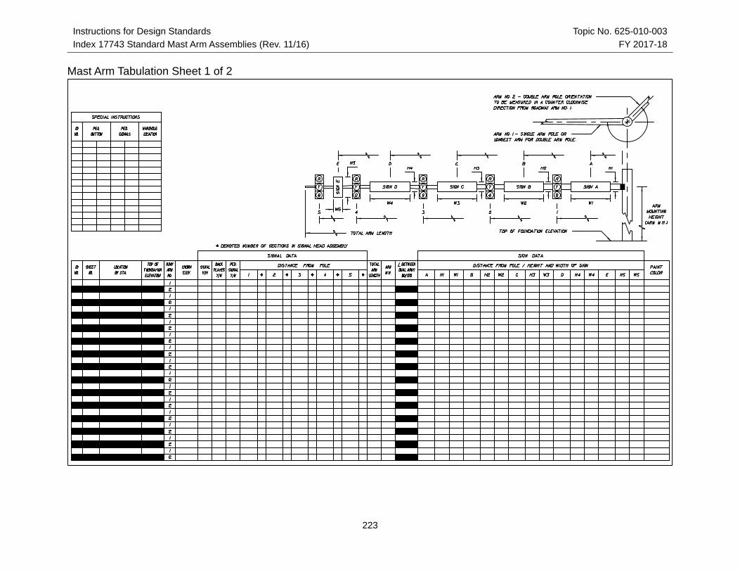
The signal designer completes the Mast Arm Tabulation Sheets, and the structures designer completes the Standard Mast Arm Assemblies Data Table, both of which will be included in the plans. These are the only plan sheets required for mast arm assemblies which meet the Department's Standard. The structures data table may be placed on a signal plan sheet, if space permits. Mast arm assemblies that do not meet the mast arm standard will require a special design (See Index 17745). See Introduction I.3 for more information regarding use of Data Tables.
The following instructions are for use with the Mast Arm Tabulation Sheets:
1. Each mast arm assembly is identified by a unique ID number.
2. Dimensions 1-5 are for signals and dimensions A-E are for signs. Record the distance from the edge of the pole, at ground level, to the center of the signal or sign.
3. Signals may be mounted vertically or horizontally. Indicate the mounting in the appropriate column in the table.
4. The entire line for arm #2 and the space for the angle between dual arms are left blank for single arm assemblies.
5. All arms and poles will be galvanized. If a color is required, indicate the color in the table, otherwise leave blank.
6. Starting at the pole, select the signals and/or signs that match the configuration you are tabulating. The spaces representing the signs or signals not used will be blank. Example 1: If no sign is located between the pole and signal 1, the spaces for Sign A would be blank. Example 2: A configuration for three signals and one sign between signal 1 and signal 2 - Only the spaces for signals 1, 2, 3 and sign B would be completed; the others will be blank.
7. Record the number of sections in each signal head in the space following the distance to that head.
8. Record the height and width of each sign in the space following the distance to the sign.
9. When double arm poles are used for a skewed intersection, the standard design should be used whenever possible. The standard orientation for arm #2 is 90 or 270 degrees measured in a counter clockwise direction from arm #1. The normal orientation of the mast arm is perpendicular to the roadway. Adjustments in mounting hardware can compensate for a skew angle of approximately 15 degrees or more from the normal, depending upon the attachment method. The designer should verify the mounting hardware capability before specifying an arm with a skew greater than 15 degrees.
10.The arm mounting height should be calculated to provide a minimum vertical clearance of 17'-6" from the roadway crown elevation to the lowest sign or signal. A standard signal section is approximately 14" square. Therefore the length of a 3-section head is about 42" and a 5-section is about 70". The use of back plates will add about 6" to each side of the signal head. Additionally, approximately 3" should be added to the end of the signal head to compensate for the attachment hardware. The
220

Instructions for Design Standards Topic No. 625-010-003
Index 17743 Standard Mast Arm Assemblies (Rev. 11/16) FY 2017-18
designer should coordinate with the maintaining agency to insure the signal assembly and all appropriate hardware has been considered in determining the vertical clearance. The maintaining agency can also provide guidance on the vertical or horizontal mounting of the signal assemblies. This information may be used to determine the arm mounting height.
11. The standard handhole location is 90 degrees from arm #1 facing away from traffic. Other handhole locations must be noted in the Special Instructions.
12.The "Special Instructions" Table is used to tabulate pedestrian buttons and pedestrian signal locations and handhole locations when the handholes are not in the standard location. Tabulate the ID No. and the orientation of the pedestrian buttons and signals in degrees measured counter clockwise from arm #1. The handhole location should be left blank if the handhole is in the standard location (see note 11).
13.Arm #1 is the arm for a single arm assembly or the longer arm for a double arm assembly. If the arms are equal length, arm #1 is over the project roadway.
221

Instructions for Design Standards Topic No. 625-010-003
Index 17743 Standard Mast Arm Assemblies (Rev. 11/16) FY 2017-18
222
Instructions for Design Standards Topic No. 625-010-003
Index 17743 Standard Mast Arm Assemblies (Rev. 11/16) FY 2017-18
223
Mast Arm Tabulation Sheet 1 of 2

Instructions for Design Standards Topic No. 625-010-003
Index 17743 Standard Mast Arm Assemblies (Rev. 11/16) FY 2017-18
224
Mast Arm Tabulation Sheet 2 of 2
Instructions for Design Standards Topic No. 625-010-003
Index 17743 Standard Mast Arm Assemblies (Rev. 11/16) FY 2017-18
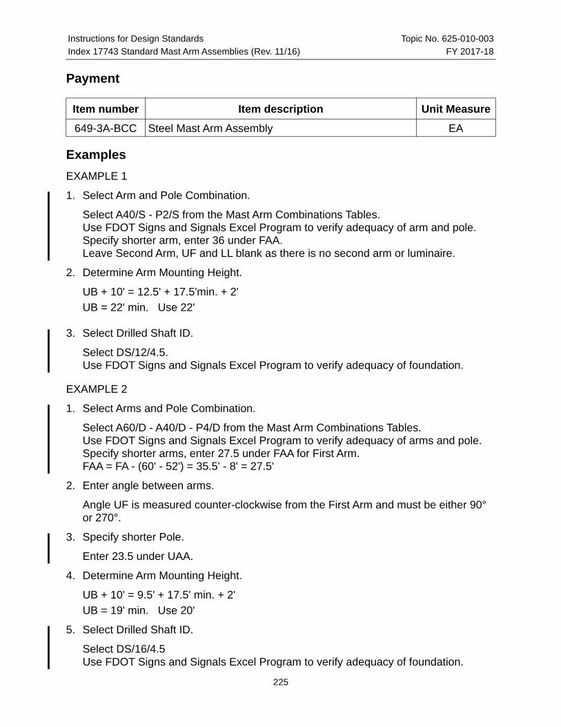
Payment
Item number Item description Unit Measure
649-3A-BCC Steel Mast Arm Assembly EA
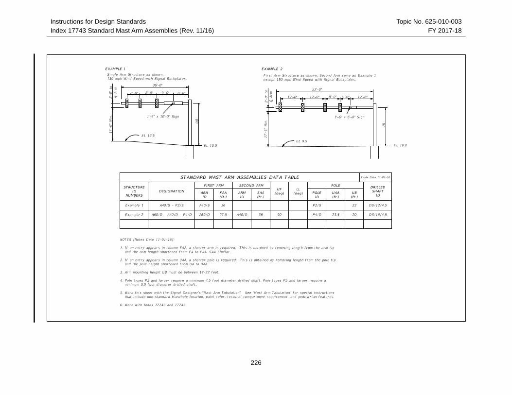
Examples
EXAMPLE 1
1. Select Arm and Pole Combination.
Select A40/S - P2/S from the Mast Arm Combinations Tables.Use FDOT Signs and Signals Excel Program to verify adequacy of arm and pole.Specify shorter arm, enter 36 under FAA.Leave Second Arm, UF and LL blank as there is no second arm or luminaire.
2. Determine Arm Mounting Height.
UB + 10' = 12.5' + 17.5'min. + 2'
UB = 22' min. Use 22'
3. Select Drilled Shaft ID.
Select DS/12/4.5.Use FDOT Signs and Signals Excel Program to verify adequacy of foundation.
EXAMPLE 2
1. Select Arms and Pole Combination.
Select A60/D - A40/D - P4/D from the Mast Arm Combinations Tables.Use FDOT Signs and Signals Excel Program to verify adequacy of arms and pole.Specify shorter arms, enter 27.5 under FAA for First Arm.FAA = FA - (60' - 52') = 35.5' - 8' = 27.5'
2. Enter angle between arms.
Angle UF is measured counter-clockwise from the First Arm and must be either 90° or 270°.
3. Specify shorter Pole.
Enter 23.5 under UAA.
4. Determine Arm Mounting Height.
UB + 10' = 9.5' + 17.5' min. + 2'
UB = 19' min. Use 20'
5. Select Drilled Shaft ID.
Select DS/16/4.5Use FDOT Signs and Signals Excel Program to verify adequacy of foundation.
225
Instructions for Design Standards Topic No. 625-010-003
Index 17743 Standard Mast Arm Assemblies (Rev. 11/16) FY 2017-18
226

Instructions for Design Standards Topic No. 625-010-003
Index 17743 Standard Mast Arm Assemblies (Rev. 11/16) FY 2017-18
227
Instructions for Design Standards Topic No. 625-010-003
Index 17743 Standard Mast Arm Assemblies (Rev. 11/16) FY 2017-18
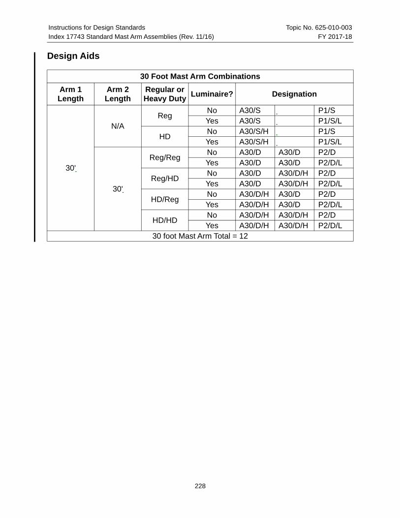
Design Aids
30 Foot Mast Arm Combinations
Arm 1 Length
Arm 2 Length
Regular or Heavy Duty
Luminaire? Designation
30'
N/AReg
No A30/S P1/SYes A30/S P1/S/L
HDNo A30/S/H P1/SYes A30/S/H P1/S/L
30'
Reg/RegNo A30/D A30/D P2/DYes A30/D A30/D P2/D/L
Reg/HDNo A30/D A30/D/H P2/DYes A30/D A30/D/H P2/D/L
HD/RegNo A30/D/H A30/D P2/DYes A30/D/H A30/D P2/D/L
HD/HDNo A30/D/H A30/D/H P2/DYes A30/D/H A30/D/H P2/D/L
30 foot Mast Arm Total = 12
228
Instructions for Design Standards Topic No. 625-010-003
Index 17743 Standard Mast Arm Assemblies (Rev. 11/16) FY 2017-18
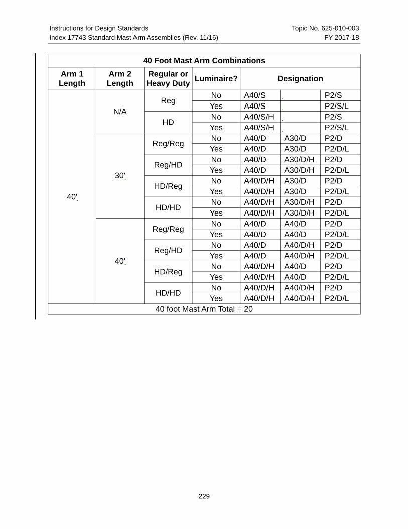
40 Foot Mast Arm Combinations
Arm 1 Length
Arm 2 Length
Regular or Heavy Duty
Luminaire? Designation
40'
N/AReg
No A40/S P2/SYes A40/S P2/S/L
HDNo A40/S/H P2/SYes A40/S/H P2/S/L
30'
Reg/RegNo A40/D A30/D P2/DYes A40/D A30/D P2/D/L
Reg/HDNo A40/D A30/D/H P2/DYes A40/D A30/D/H P2/D/L
HD/RegNo A40/D/H A30/D P2/DYes A40/D/H A30/D P2/D/L
HD/HDNo A40/D/H A30/D/H P2/DYes A40/D/H A30/D/H P2/D/L
40'
Reg/RegNo A40/D A40/D P2/DYes A40/D A40/D P2/D/L
Reg/HDNo A40/D A40/D/H P2/DYes A40/D A40/D/H P2/D/L
HD/RegNo A40/D/H A40/D P2/DYes A40/D/H A40/D P2/D/L
HD/HDNo A40/D/H A40/D/H P2/DYes A40/D/H A40/D/H P2/D/L
40 foot Mast Arm Total = 20
229

Instructions for Design Standards Topic No. 625-010-003
Index 17743 Standard Mast Arm Assemblies (Rev. 11/16) FY 2017-18
50 Foot Mast Arm Combinations
Arm 1 Length
Arm 2 Length
Regular or Heavy Duty
Luminaire? Designation
50'
N/AReg
No A50/S P3/SYes A50/S P3/S/L
HDNo A50/S/H P3/SYes A50/S/H P3/S/L
30'
Reg/RegNo A50/D A30/D P3/DYes A50/D A30/D P3/D/L
Reg/HDNo A50/D A30/D/H P3/DYes A50/D A30/D/H P3/D/L
HD/RegNo A50/D/H A30/D P3/DYes A50/D/H A30/D P3/D/L
HD/HDNo A50/D/H A30/D/H P3/DYes A50/D/H A30/D/H P3/D/L
40'
Reg/RegNo A50/D A40/D P3/DYes A50/D A40/D P3/D/L
Reg/HDNo A50/D A40/D/H P3/DYes A50/D A40/D/H P3/D/L
HD/RegNo A50/D/H A40/D P3/DYes A50/D/H A40/D P3/D/L
HD/HDNo A50/D/H A40/D/H P3/DYes A50/D/H A40/D/H P3/D/L
50'
Reg/RegNo A50/D A50/D P3/DYes A50/D A50/D P3/D/L
Reg/HDNo A50/D A50/D/H P3/DYes A50/D A50/D/H P3/D/L
HD/RegNo A50/D/H A50/D P3/DYes A50/D/H A50/D P3/D/L
HD/HDNo A50/D/H A50/D/H P3/DYes A50/D/H A50/D/H P3/D/L
50 foot Mast Arm Total = 28
230

Instructions for Design Standards Topic No. 625-010-003
Index 17743 Standard Mast Arm Assemblies (Rev. 11/16) FY 2017-18
60 Foot Mast Arm Combinations
Arm 1 Length
Arm 2 Length
Regular or Heavy Duty
Luminaire? Designation
60'
N/AReg
No A60/S P4/SYes A60/S P4/S/L
HDNo A60/S/H P4/SYes A60/S/H P4/S/L
30'
Reg/RegNo A60/D A30/D P4/DYes A60/D A30/D P4/D/L
Reg/HDNo A60/D A30/D/H P4/DYes A60/D A30/D/H P4/D/L
HD/RegNo A60/D/H A30/D P4/DYes A60/D/H A30/D P4/D/L
HD/HDNo A60/D/H A30/D/H P4/DYes A60/D/H A30/D/H P4/D/L
40'
Reg/RegNo A60/D A40/D P4/DYes A60/D A40/D P4/D/L
Reg/HDNo A60/D A40/D/H P4/DYes A60/D A40/D/H P4/D/L
HD/RegNo A60/D/H A40/D P4/DYes A60/D/H A40/D P4/D/L
HD/HDNo A60/D/H A40/D/H P4/DYes A60/D/H A40/D/H P4/D/L
50'
Reg/RegNo A60/D A50/D P4/DYes A60/D A50/D P4/D/L
Reg/HDNo A60/D A50/D/H P4/DYes A60/D A50/D/H P4/D/L
HD/RegNo A60/D/H A50/D P4/DYes A60/D/H A50/D P4/D/L
HD/HDNo A60/D/H A50/D/H P4/DYes A60/D/H A50/D/H P4/D/L
60'
Reg/RegNo A60/D A60/D P5/DYes A60/D A60/D P5/D/L
Reg/HDNo A60/D A60/D/H P5/DYes A60/D A60/D/H P5/D/L
HD/RegNo A60/D/H A60/D P5/DYes A60/D/H A60/D P5/D/L
HD/HDNo A60/D/H A60/D/H P5/DYes A60/D/H A60/D/H P5/D/L
60 foot Mast Arm Total = 36
231
Instructions for Design Standards Topic No. 625-010-003
Index 17743 Standard Mast Arm Assemblies (Rev. 11/16) FY 2017-18
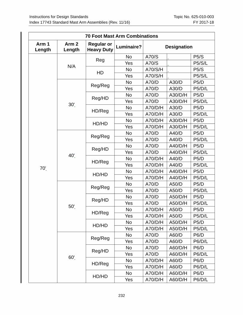
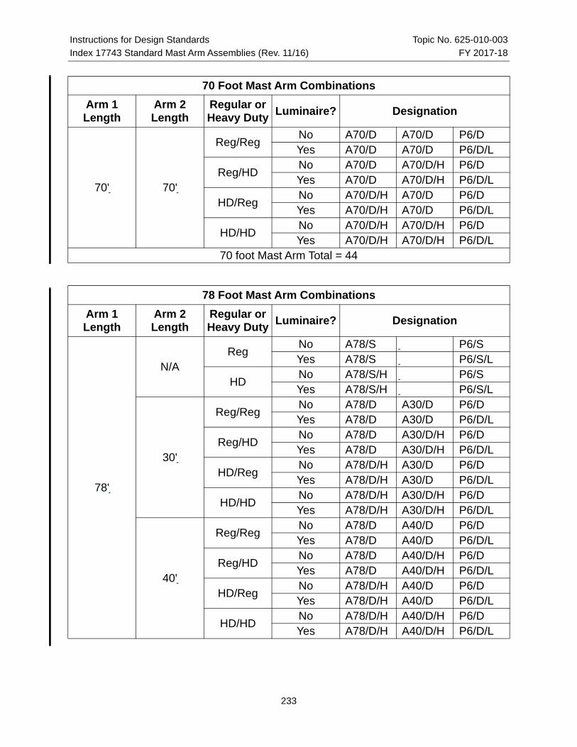
70 Foot Mast Arm Combinations
Arm 1 Length
Arm 2 Length
Regular or Heavy Duty
Luminaire? Designation
70'
N/AReg
No A70/S P5/SYes A70/S P5/S/L
HDNo A70/S/H P5/SYes A70/S/H P5/S/L
30'
Reg/RegNo A70/D A30/D P5/DYes A70/D A30/D P5/D/L
Reg/HDNo A70/D A30/D/H P5/DYes A70/D A30/D/H P5/D/L
HD/RegNo A70/D/H A30/D P5/DYes A70/D/H A30/D P5/D/L
HD/HDNo A70/D/H A30/D/H P5/DYes A70/D/H A30/D/H P5/D/L
40'
Reg/RegNo A70/D A40/D P5/DYes A70/D A40/D P5/D/L
Reg/HDNo A70/D A40/D/H P5/DYes A70/D A40/D/H P5/D/L
HD/RegNo A70/D/H A40/D P5/DYes A70/D/H A40/D P5/D/L
HD/HDNo A70/D/H A40/D/H P5/DYes A70/D/H A40/D/H P5/D/L
50'
Reg/RegNo A70/D A50/D P5/DYes A70/D A50/D P5/D/L
Reg/HDNo A70/D A50/D/H P5/DYes A70/D A50/D/H P5/D/L
HD/RegNo A70/D/H A50/D P5/DYes A70/D/H A50/D P5/D/L
HD/HDNo A70/D/H A50/D/H P5/DYes A70/D/H A50/D/H P5/D/L
60'
Reg/RegNo A70/D A60/D P6/DYes A70/D A60/D P6/D/L
Reg/HDNo A70/D A60/D/H P6/DYes A70/D A60/D/H P6/D/L
HD/RegNo A70/D/H A60/D P6/DYes A70/D/H A60/D P6/D/L
HD/HDNo A70/D/H A60/D/H P6/DYes A70/D/H A60/D/H P6/D/L
232
Instructions for Design Standards Topic No. 625-010-003
Index 17743 Standard Mast Arm Assemblies (Rev. 11/16) FY 2017-18
70' 70'
Reg/RegNo A70/D A70/D P6/DYes A70/D A70/D P6/D/L
Reg/HDNo A70/D A70/D/H P6/DYes A70/D A70/D/H P6/D/L
HD/RegNo A70/D/H A70/D P6/DYes A70/D/H A70/D P6/D/L
HD/HDNo A70/D/H A70/D/H P6/DYes A70/D/H A70/D/H P6/D/L
70 foot Mast Arm Total = 44
78 Foot Mast Arm Combinations
Arm 1 Length
Arm 2 Length
Regular or Heavy Duty
Luminaire? Designation
78'
N/AReg
No A78/S P6/SYes A78/S P6/S/L
HDNo A78/S/H P6/SYes A78/S/H P6/S/L
30'
Reg/RegNo A78/D A30/D P6/DYes A78/D A30/D P6/D/L
Reg/HDNo A78/D A30/D/H P6/DYes A78/D A30/D/H P6/D/L
HD/RegNo A78/D/H A30/D P6/DYes A78/D/H A30/D P6/D/L
HD/HDNo A78/D/H A30/D/H P6/DYes A78/D/H A30/D/H P6/D/L
40'
Reg/RegNo A78/D A40/D P6/DYes A78/D A40/D P6/D/L
Reg/HDNo A78/D A40/D/H P6/DYes A78/D A40/D/H P6/D/L
HD/RegNo A78/D/H A40/D P6/DYes A78/D/H A40/D P6/D/L
HD/HDNo A78/D/H A40/D/H P6/DYes A78/D/H A40/D/H P6/D/L
70 Foot Mast Arm Combinations
Arm 1 Length
Arm 2 Length
Regular or Heavy Duty
Luminaire? Designation
233

Instructions for Design Standards Topic No. 625-010-003
Index 17743 Standard Mast Arm Assemblies (Rev. 11/16) FY 2017-18
78'
50'
Reg/RegNo A78/D A50/D P6/DYes A78/D A50/D P6/D/L
Reg/HDNo A78/D A50/D/H P6/DYes A78/D A50/D/H P6/D/L
HD/RegNo A78/D/H A50/D P6/DYes A78/D/H A50/D P6/D/L
HD/HDNo A78/D/H A50/D/H P6/DYes A78/D/H A50/D/H P6/D/L
60'
Reg/RegNo A78/D A60/D P6/DYes A78/D A60/D P6/D/L
Reg/HDNo A78/D A60/D/H P6/DYes A78/D A60/D/H P6/D/L
HD/RegNo A78/D/H A60/D P6/DYes A78/D/H A60/D P6/D/L
HD/HDNo A78/D/H A60/D/H P6/DYes A78/D/H A60/D/H P6/D/L
70'
Reg/RegNo A78/D A70/D P7/DYes A78/D A70/D P7/D/L
Reg/HDNo A78/D A70/D/H P7/DYes A78/D A70/D/H P7/D/L
HD/RegNo A78/D/H A70/D P7/DYes A78/D/H A70/D P7/D/L
HD/HDNo A78/D/H A70/D/H P7/DYes A78/D/H A70/D/H P7/D/L
78'
Reg/RegNo A78/D A78/D P7/DYes A78/D A78/D P7/D/L
Reg/HDNo A78/D A78/D/H P7/DYes A78/D A78/D/H P7/D/L
HD/RegNo A78/D/H A78/D P7/DYes A78/D/H A78/D P7/D/L
HD/HDNo A78/D/H A78/D/H P7/DYes A78/D/H A78/D/H P7/D/L
78 foot Mast Arm Total = 52
78 Foot Mast Arm Combinations
Arm 1 Length
Arm 2 Length
Regular or Heavy Duty
Luminaire? Designation
234