IND246 and IND246 POWERCELL User's Guide Weighing …Service IND246 and IND246 POWERCELL Weighing...
257
User's Guide IND246 and IND246 POWERCELL Weighing Terminal
Transcript of IND246 and IND246 POWERCELL User's Guide Weighing …Service IND246 and IND246 POWERCELL Weighing...
User
's G
uide
IND246 and IND246 POWERCELL Weighing Terminal

Serv
ice
IND246 and IND246 POWERCELL Weighing Terminal
METTLER TOLEDO Service
Essential Services for Dependable Performance of Your IND246 and IND246 POWERCELL Weighing Terminal
Congratulations on choosing the quality and precision of METTLER TOLEDO. Proper use of your new equipment according to this Manual and regular calibration and maintenance by our factory-trained service team ensures dependable and accurate operation, protecting your investment. Contact us about a service agreement tailored to your needs and budget. Further information is available at www.mt.com/service.
There are several important ways to ensure you maximize the performance of your investment:
1. Register your product: We invite you to register your product at www.mt.com/productregistration so we can contact you about enhancements, updates and important notifications concerning your product.
2. Contact METTLER TOLEDO for service: The value of a measurement is proportional to its accuracy – an out of specification scale can diminish quality, reduce profits and increase liability. Timely service from METTLER TOLEDO will ensure accuracy and optimize uptime and equipment life.
a. Installation, Configuration, Integration and Training: Our service representatives are factory-trained, weighing equipment experts. We make certain that your weighing equipment is ready for production in a cost effective and timely fashion and that personnel are trained for success.
b. Initial Calibration Documentation: The installation environment and application requirements are unique for every industrial scale so performance must be tested and certified. Our calibration services and certificates document accuracy to ensure production quality and provide a quality system record of performance.
c. Periodic Calibration Maintenance: A Calibration Service Agreement provides on-going confidence in your weighing process and documentation of compliance with requirements. We offer a variety of service plans that are scheduled to meet your needs and designed to fit your budget.
d. GWP® Verification: A risk-based approach for managing weighing equipment allows for control and improvement of the entire measuring process, which ensures reproducible product quality and minimizes process costs. GWP (Good Weighing Practice), the science-based standard for efficient life-cycle management of weighing equipment, gives clear answers about how to specify, calibrate and ensure accuracy of weighing equipment, independent of make or brand.
© METTLER TOLEDO 2017 No part of this manual may be reproduced or transmitted in any form or by any means, electronic or mechanical, including photocopying and recording, for any purpose without the express written permission of METTLER TOLEDO. U.S. Government Restricted Rights: This documentation is furnished with Restricted Rights.
Copyright 2017 METTLER TOLEDO. This documentation contains proprietary information of METTLER TOLEDO. It may not be copied in whole or in part without the express written consent of METTLER TOLEDO. METTLER TOLEDO reserves the right to make refinements or changes to the product or manual without notice.
COPYRIGHT METTLER TOLEDO® is a registered trademark of Mettler-Toledo, LLC. All other brand or product names are trademarks or registered trademarks of their respective companies.
METTLER TOLEDO RESERVES THE RIGHT TO MAKE REFINEMENTS OR CHANGES WITHOUT NOTICE.
FCC Notice This device complies with Part 15 of the FCC Rules and the Radio Interference Requirements of the Canadian Department of Communications. Operation is subject to the following conditions: (1) this device may not cause harmful interference, and (2) this device must accept any interference received, including interference that may cause undesired operation. This equipment has been tested and found to comply with the limits for a Class A digital device, pursuant to Part 15 of FCC Rules. These limits are designed to provide reasonable protection against harmful interference when the equipment is operated in a commercial environment. This equipment generates, uses, and can radiate radio frequency energy and, if not installed and used in accordance with the instruction manual, may cause harmful interference to radio communications. Operation of this equipment in a residential area is likely to cause harmful interference in which case the user will be required to correct the interference at his or her expense.
Declaration of Conformity is available at http://glo.mt.com/global/en/home/search/compliance.html/compliance/.
© METTLER TOLEDO Error! Unknown document property name.
No part of this manual may be reproduced or transmitted in any form or by any means, electronic or mechanical, including photocopying and recording, for any purpose without the express written permission of METTLER TOLEDO.
U.S. Government Restricted Rights: This documentation is furnished with Restricted Rights.
Copyright Error! Unknown document property name. METTLER TOLEDO. This documentation contains proprietary information of METTLER TOLEDO. It may not be copied in whole or in part without the express written consent of METTLER TOLEDO.
METTLER TOLEDO reserves the right to make refinements or changes to the product or manual without notice.
COPYRIGHT METTLER TOLEDO® is a registered trademark of Mettler-Toledo, LLC. All other brand or product names are trademarks or registered trademarks of their respective companies.
METTLER TOLEDO RESERVES THE RIGHT TO MAKE REFINEMENTS OR CHANGES WITHOUT NOTICE.
FCC Notice This device complies with Part 15 of the FCC Rules and the Radio Interference Requirements of the Canadian Department of Communications. Operation is subject to the following conditions: (1) this device may not cause harmful interference, and (2) this device must accept any interference received, including interference that may cause undesired operation.
This equipment has been tested and found to comply with the limits for a Class A digital device, pursuant to Part 15 of FCC Rules. These limits are designed to provide reasonable protection against harmful interference when the equipment is operated in a commercial environment. This equipment generates, uses, and can radiate radio frequency energy and, if not installed and used in accordance with the instruction manual, may cause harmful interference to radio communications. Operation of this equipment in a residential area is likely to cause harmful interference in which case the user will be required to correct the interference at his or her expense.
Declaration of Conformity is available at http://glo.mt.com/global/en/home/search/compliance.html/compliance/.
Disposal of Electrical and Electronic Equipment
In conformance with the European Directive 2002/96/EC on Waste Electrical and Electronic Equipment (WEEE) this device may not be disposed of in domestic waste. This also applies to countries outside the EU, per their specific requirements.
Please dispose of this product in accordance with local regulations at the collecting point specified for electrical and electronic equipment.
If you have any questions, please contact the responsible authority or the distributor from which you purchased this device.
Should this device be passed on to other parties (for private or professional use), the content of this regulation must also be related.
Thank you for your contribution to environmental protection.
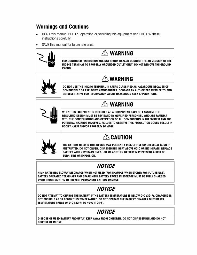
Warnings and Cautions • READ this manual BEFORE operating or servicing this equipment and FOLLOW these
instructions carefully.
• SAVE this manual for future reference.
WARNING FOR CONTINUED PROTECTION AGAINST SHOCK HAZARD CONNECT THE AC VERSION OF THE IND246 TERMINAL TO PROPERLY GROUNDED OUTLET ONLY. DO NOT REMOVE THE GROUND PRONG.
WARNING DO NOT USE THE IND246 TERMINAL IN AREAS CLASSIFIED AS HAZARDOUS BECAUSE OF COMBUSTIBLE OR EXPLOSIVE ATMOSPHERES. CONTACT AN AUTHORIZED METTLER TOLEDO REPRESENTATIVE FOR INFORMATION ABOUT HAZARDOUS AREA APPLICATIONS.
WARNING WHEN THIS EQUIPMENT IS INCLUDED AS A COMPONENT PART OF A SYSTEM, THE RESULTING DESIGN MUST BE REVIEWED BY QUALIFIED PERSONNEL WHO ARE FAMILIAR WITH THE CONSTRUCTION AND OPERATION OF ALL COMPONENTS IN THE SYSTEM AND THE POTENTIAL HAZARDS INVOLVED. FAILURE TO OBSERVE THIS PRECAUTION COULD RESULT IN BODILY HARM AND/OR PROPERTY DAMAGE.
CAUTION THE BATTERY USED IN THIS DEVICE MAY PRESENT A RISK OF FIRE OR CHEMICAL BURN IF MISTREATED. DO NOT CRUSH, DISASSEMBLE, HEAT ABOVE 60°C OR INCINERATE. REPLACE BATTERY WITH 72253419 ONLY. USE OF ANOTHER BATTERY MAY PRESENT A RISK OF BURN, FIRE OR EXPLOSION.
NOTICE NiMH BATTERIES SLOWLY DISCHARGE WHEN NOT USED (FOR EXAMPLE WHEN STORED FOR FUTURE USE). BATTERY OPERATED TERMINALS AND SPARE NiMH BATTERY PACKS IN STORAGE MUST BE FULLY CHARGED EVERY THREE MONTHS TO PREVENT PERMANENT BATTERY DAMAGE.
NOTICE DO NOT ATTEMPT TO CHARGE THE BATTERY IF THE BATTERY TEMPERATURE IS BELOW 0°C (32°F). CHARGING IS NOT POSSIBLE AT OR BELOW THIS TEMPERATURE. DO NOT OPERATE THE BATTERY CHARGER OUTSIDE ITS TEMPERATURE RANGE OF 0°C (32°F) TO 40°C (104°F).
NOTICE DISPOSE OF USED BATTERY PROMPTLY. KEEP AWAY FROM CHILDREN. DO NOT DISASSEMBLE AND DO NOT DISPOSE OF IN FIRE.

War
ning
s an
d Ca
utio
ns
NOTICE OBSERVE PRECAUTIONS FOR HANDLING ELECTROSTATIC SENSITIVE DEVICES.
64084448 / Rev. 03 / 12/2017 METTLER TOLEDO IND246 and IND246 POWERCELL Weighing Terminal User's Guide 1
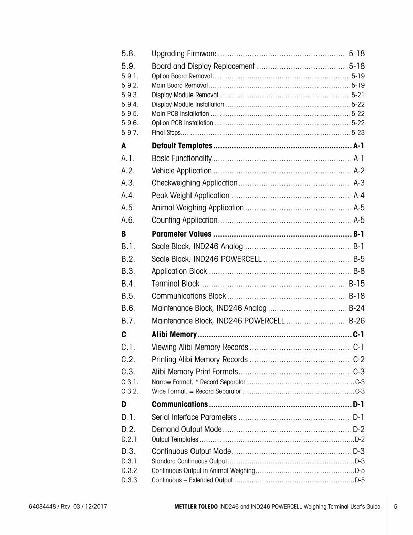
Contents 1 Introduction ...................................................................... 1-1
1.1. IND246 Overview ............................................................... 1-1 1.1.1. Standard Features .................................................................................. 1-1 1.1.2. IND246 Terminal Versions ...................................................................... 1-2
1.2. Specifications .................................................................... 1-2
1.3. Battery Performance ........................................................... 1-5
1.4. Use in Hazardous Areas ...................................................... 1-6
1.5. Inspection and Contents Checklist ........................................ 1-6
1.6. Model Identification ............................................................ 1-7
1.7. Physical Dimensions .......................................................... 1-8
1.8. Main PCB .......................................................................... 1-9 1.8.1. SD Memory ........................................................................................... 1-9
1.9. Scale Bases ...................................................................... 1-9 1.9.1. Analog .................................................................................................. 1-9 1.9.2. POWERCELL .......................................................................................... 1-9 1.9.3. PowerDeck .......................................................................................... 1-10
1.10. Options ........................................................................... 1-10 1.10.1. COM2 Serial Port .................................................................................. 1-10 1.10.2. Discrete I/O .......................................................................................... 1-11 1.10.3. USB .................................................................................................... 1-11 1.10.4. Ethernet ............................................................................................... 1-11
1.11. Display and Keyboard ...................................................... 1-12 1.11.1. Display Layout ..................................................................................... 1-12 1.11.2. Front Panel Keys .................................................................................. 1-12
2 Operation: Terminal .......................................................... 2-1
2.1. Overview ........................................................................... 2-1
2.2. Display Elements and Keypad Operation ............................... 2-1 2.2.1. Display Elements ................................................................................... 2-1 2.2.2. Keypad Operation ................................................................................... 2-3
2.3. Operator Menu ................................................................... 2-6 2.3.1. Language Selection – F Codes ................................................................. 2-6 2.3.2. Menu Navigation .................................................................................... 2-6 2.3.3. Alibi Memory ......................................................................................... 2-9 2.3.4. Adjust Contrast ....................................................................................... 2-9 2.3.5. Transaction Counter .............................................................................. 2-10 2.3.6. Totals Memory ..................................................................................... 2-10 2.3.7. Expand x 10 ........................................................................................ 2-10 2.3.8. Information Recall ................................................................................ 2-11 2.3.9. Setup Access ....................................................................................... 2-12
2 METTLER TOLEDO IND246 and IND246 POWERCELL Weighing Terminal User's Guide 64084448 / Rev. 03 / 12/2017
Cont
ents
2.4. Basic Functionality ........................................................... 2-12 2.4.1. Zero .................................................................................................... 2-12 2.4.2. Tare .................................................................................................... 2-13 2.4.3. Unit Switching ...................................................................................... 2-17 2.4.4. Expand By 10 ...................................................................................... 2-17 2.4.5. Print .................................................................................................... 2-17 2.4.6. Information Recall ................................................................................ 2-18 2.4.7. ID Entry ............................................................................................... 2-18 2.4.8. Time and Date ..................................................................................... 2-19 2.4.9. Totalization .......................................................................................... 2-19 2.4.10. Alibi Memory ....................................................................................... 2-19
2.5. Applications .................................................................... 2-20 2.5.1. Animal Weighing .................................................................................. 2-20 2.5.2. Checkweighing .................................................................................... 2-20 2.5.3. Counting ............................................................................................. 2-21 2.5.4. Peak Weight ........................................................................................ 2-21 2.5.5. Vehicle Weighing ................................................................................. 2-22
3 Configuration: Terminal ..................................................... 3-1
3.1. Entering Setup Mode ........................................................... 3-1
3.2. Security ............................................................................. 3-1
3.3. Exiting Setup Mode ............................................................. 3-2
3.4. Setup Menu Structure .......................................................... 3-2 3.4.1. Navigation ............................................................................................. 3-2 3.4.2. Setup Page ............................................................................................ 3-2
3.5. Configuration: Overview ...................................................... 3-5
3.6. Configuration: Scale ........................................................... 3-6 3.6.1. Type ..................................................................................................... 3-6 3.6.2. Load Cell ............................................................................................... 3-7 3.6.3. Capacity and Increment ........................................................................ 3-11 3.6.4. Calibration ........................................................................................... 3-13 3.6.5. Zero .................................................................................................... 3-14 3.6.6. Tare .................................................................................................... 3-15 3.6.7. Units ................................................................................................... 3-17 3.6.8. Filter ................................................................................................... 3-17 3.6.9. Stability ............................................................................................... 3-18 3.6.10. Log or Print ......................................................................................... 3-18 3.6.11. Scale Reset .......................................................................................... 3-19
3.7. Configuration: Application ................................................. 3-20 3.7.1. Memory............................................................................................... 3-20 3.7.2. Totalization .......................................................................................... 3-20 3.7.3. Discrete I/O .......................................................................................... 3-21 3.7.4. Function Key ........................................................................................ 3-21 3.7.5. Animal Weighing .................................................................................. 3-22
64084448 / Rev. 03 / 12/2017 METTLER TOLEDO IND246 and IND246 POWERCELL Weighing Terminal User's Guide 3
3.7.6. Counting ............................................................................................. 3-23 3.7.7. Checkweighing .................................................................................... 3-24 3.7.8. Peak Weight ........................................................................................ 3-25 3.7.9. Vehicle Weighing ................................................................................. 3-26 3.7.10. Reset .................................................................................................. 3-26
3.8. Configuration: Terminal ..................................................... 3-27 3.8.1. Device ................................................................................................. 3-27 3.8.2. Display ............................................................................................... 3-27 3.8.3. Region ................................................................................................ 3-28 3.8.4. Transaction Counter .............................................................................. 3-30 3.8.5. User .................................................................................................... 3-30 3.8.6. Menu Keys .......................................................................................... 3-30 3.8.7. Reset .................................................................................................. 3-31
3.9. Configuration: Communication ........................................... 3-31 3.9.1. Templates............................................................................................ 3-31 3.9.2. Reports ............................................................................................... 3-33 3.9.3. Connections ........................................................................................ 3-33 3.9.4. Serial .................................................................................................. 3-36 3.9.5. Network............................................................................................... 3-38 3.9.6. Reset .................................................................................................. 3-39
3.10. Configuration: Maintenance ............................................... 3-39 3.10.1. Diagnostics ......................................................................................... 3-39 3.10.2. Scale .................................................................................................. 3-39 3.10.3. Replace Battery .................................................................................... 3-47 3.10.4. Install Software Update .......................................................................... 3-47 3.10.5. Backup to SD ....................................................................................... 3-47 3.10.6. Restore from SD ................................................................................... 3-47 3.10.7. POWERCELL Maintenance ..................................................................... 3-47 3.10.8. Reset All - Factory Default Settings.......................................................... 3-52
3.11. Restoring Factory Default Settings ....................................... 3-52
4 Applications: Configuration and Operation .......................... 4-1
4.1. Introduction ....................................................................... 4-1
4.2. Animal Weighing ................................................................ 4-1 4.2.1. Overview ............................................................................................... 4-1 4.2.2. Operational Features ............................................................................... 4-2 4.2.3. Configuration ......................................................................................... 4-3 4.2.4. Operating Sequence ................................................................................ 4-4 4.2.5. Remote Displays .................................................................................... 4-6 4.2.6. Serial Input Commands ........................................................................... 4-6 4.2.7. Print Formats ......................................................................................... 4-6
4.3. Checkweighing (Over/Under) ............................................... 4-8 4.3.1. Overview ............................................................................................... 4-8 4.3.2. Operational Features ............................................................................... 4-8 4.3.3. Configuration ......................................................................................... 4-9
4 METTLER TOLEDO IND246 and IND246 POWERCELL Weighing Terminal User's Guide 64084448 / Rev. 03 / 12/2017
Cont
ents
4.3.4. Operating Sequence .............................................................................. 4-14 4.3.5. Print Formats ....................................................................................... 4-18
4.4. Counting ......................................................................... 4-20 4.4.1. Overview ............................................................................................. 4-20 4.4.2. Operational Features ............................................................................. 4-21 4.4.3. Configuration ....................................................................................... 4-21 4.4.4. Operating Sequences ............................................................................ 4-24 4.4.5. Print Formats ....................................................................................... 4-28
4.5. Peak Weight Measurement ................................................ 4-30 4.5.1. Overview ............................................................................................. 4-30 4.5.2. Operational Features ............................................................................. 4-30 4.5.3. Configuration ....................................................................................... 4-31 4.5.4. Operating Sequences ............................................................................ 4-32 4.5.5. Memory Operation ................................................................................ 4-34 4.5.6. Print Formats ....................................................................................... 4-35
4.6. Vehicle Weighing ............................................................. 4-37 4.6.1. Overview ............................................................................................. 4-37 4.6.2. Operational Features ............................................................................. 4-38 4.6.3. Configuration ....................................................................................... 4-38 4.6.4. Operating Sequences ............................................................................ 4-42 4.6.5. Print Formats ....................................................................................... 4-47
5 Service and Maintenance .................................................. 5-1
5.1. Cleaning and Maintenance .................................................. 5-1
5.2. Service .............................................................................. 5-1
5.3. Battery Operation ................................................................ 5-2 5.3.1. Specifications ........................................................................................ 5-2 5.3.2. Battery Status Icon .................................................................................. 5-3 5.3.3. Accessing the Battery Pack ...................................................................... 5-3 5.3.4. Charging the Battery Pack ....................................................................... 5-5 5.3.5. Disposing of a Depleted Battery Pack ....................................................... 5-7
5.4. Troubleshooting ................................................................. 5-7 5.4.1. Blank Display ........................................................................................ 5-7 5.4.2. Power Test............................................................................................. 5-8 5.4.3. Problem Diagnosis ................................................................................. 5-8 5.4.4. Error Codes and Error Messages .............................................................. 5-9 5.4.5. Internal Diagnostics .............................................................................. 5-11
5.5. Replacing BRAM Battery .................................................... 5-14
5.6. System Backup and Restore .............................................. 5-15 5.6.1. Files, Media and Data ........................................................................... 5-15 5.6.2. Backup to SD Memory Card ................................................................... 5-16 5.6.3. Restore from SD Memory Card ............................................................... 5-16
5.7. Master Reset .................................................................... 5-17
64084448 / Rev. 03 / 12/2017 METTLER TOLEDO IND246 and IND246 POWERCELL Weighing Terminal User's Guide 5
5.8. Upgrading Firmware ......................................................... 5-18
5.9. Board and Display Replacement ........................................ 5-18 5.9.1. Option Board Removal .......................................................................... 5-19 5.9.2. Main Board Removal ............................................................................ 5-19 5.9.3. Display Module Removal ...................................................................... 5-21 5.9.4. Display Module Installation ................................................................... 5-22 5.9.5. Main PCB Installation ........................................................................... 5-22 5.9.6. Option PCB Installation ......................................................................... 5-22 5.9.7. Final Steps........................................................................................... 5-23
A Default Templates ............................................................. A-1
A.1. Basic Functionality ............................................................. A-1
A.2. Vehicle Application ............................................................. A-2
A.3. Checkweighing Application .................................................. A-3
A.4. Peak Weight Application ..................................................... A-4
A.5. Animal Weighing Application ............................................... A-5
A.6. Counting Application ........................................................... A-5
B Parameter Values ............................................................. B-1
B.1. Scale Block, IND246 Analog ............................................... B-1
B.2. Scale Block, IND246 POWERCELL ....................................... B-5
B.3. Application Block ............................................................... B-8
B.4. Terminal Block ................................................................. B-15
B.5. Communications Block ..................................................... B-18
B.6. Maintenance Block, IND246 Analog ................................... B-24
B.7. Maintenance Block, IND246 POWERCELL ........................... B-26
C Alibi Memory .................................................................... C-1
C.1. Viewing Alibi Memory Records ............................................. C-1
C.2. Printing Alibi Memory Records ............................................. C-2
C.3. Alibi Memory Print Formats .................................................. C-3 C.3.1. Narrow Format, * Record Separator .......................................................... C-3 C.3.2. Wide Format, = Record Separator ............................................................ C-3
D Communications ............................................................... D-1
D.1. Serial Interface Parameters .................................................. D-1
D.2. Demand Output Mode ......................................................... D-2 D.2.1. Output Templates ................................................................................... D-2
D.3. Continuous Output Mode ..................................................... D-3 D.3.1. Standard Continuous Output .................................................................... D-3 D.3.2. Continuous Output in Animal Weighing ..................................................... D-5 D.3.3. Continuous – Extended Output ................................................................. D-5
6 METTLER TOLEDO IND246 and IND246 POWERCELL Weighing Terminal User's Guide 64084448 / Rev. 03 / 12/2017
Cont
ents
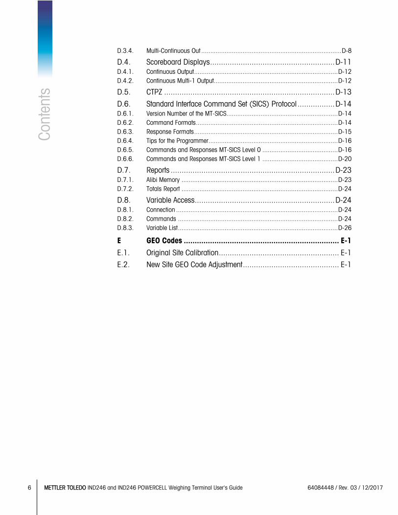
D.3.4. Multi-Continuous Out .............................................................................. D-8
D.4. Scoreboard Displays ......................................................... D-11 D.4.1. Continuous Output ................................................................................ D-12 D.4.2. Continuous Multi-1 Output ..................................................................... D-12
D.5. CTPZ .............................................................................. D-13
D.6. Standard Interface Command Set (SICS) Protocol ................. D-14 D.6.1. Version Number of the MT-SICS.............................................................. D-14 D.6.2. Command Formats ............................................................................... D-14 D.6.3. Response Formats ................................................................................ D-15 D.6.4. Tips for the Programmer ........................................................................ D-16 D.6.5. Commands and Responses MT-SICS Level 0 .......................................... D-16 D.6.6. Commands and Responses MT-SICS Level 1 .......................................... D-20
D.7. Reports ........................................................................... D-23 D.7.1. Alibi Memory ....................................................................................... D-23 D.7.2. Totals Report ....................................................................................... D-24
D.8. Variable Access ................................................................ D-24 D.8.1. Connection .......................................................................................... D-24 D.8.2. Commands ......................................................................................... D-24 D.8.3. Variable List ......................................................................................... D-26
E GEO Codes ....................................................................... E-1
E.1. Original Site Calibration ....................................................... E-1
E.2. New Site GEO Code Adjustment ............................................ E-1
64084448 | 03 | 12/2017 METTLER TOLEDO IND246 and IND246 POWERCELL User's Guide 1-1
This chapter covers
• Overview
• Specifications
• Use in Hazardous Areas
• Safe Disposal Requirement
• Inspection and Contents Checklist
• Model Identification
• Physical Dimensions
• Main PCB
• Scale Bases
• Options
• Display and Keyboard
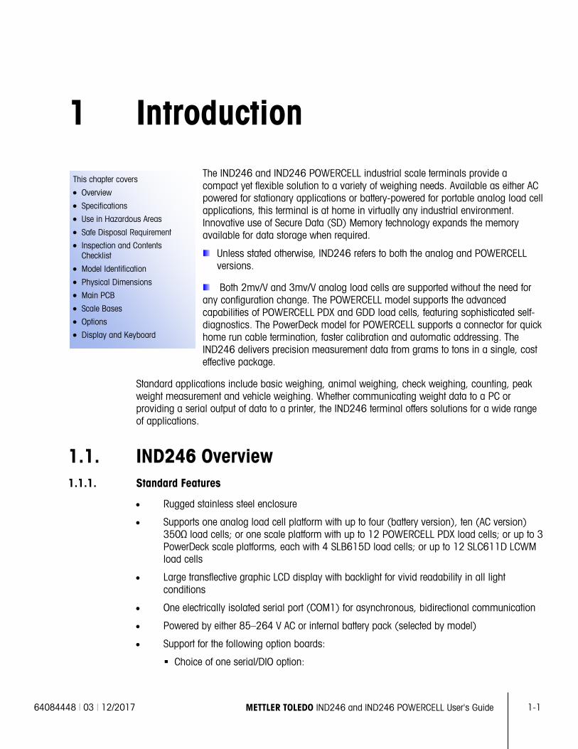
1 Introduction The IND246 and IND246 POWERCELL industrial scale terminals provide a compact yet flexible solution to a variety of weighing needs. Available as either AC powered for stationary applications or battery-powered for portable analog load cell applications, this terminal is at home in virtually any industrial environment. Innovative use of Secure Data (SD) Memory technology expands the memory available for data storage when required.
Unless stated otherwise, IND246 refers to both the analog and POWERCELL versions.
Both 2mv/V and 3mv/V analog load cells are supported without the need for any configuration change. The POWERCELL model supports the advanced capabilities of POWERCELL PDX and GDD load cells, featuring sophisticated self-diagnostics. The PowerDeck model for POWERCELL supports a connector for quick home run cable termination, faster calibration and automatic addressing. The IND246 delivers precision measurement data from grams to tons in a single, cost effective package.
Standard applications include basic weighing, animal weighing, check weighing, counting, peak weight measurement and vehicle weighing. Whether communicating weight data to a PC or providing a serial output of data to a printer, the IND246 terminal offers solutions for a wide range of applications.
1.1. IND246 Overview 1.1.1. Standard Features
• Rugged stainless steel enclosure
• Supports one analog load cell platform with up to four (battery version), ten (AC version) 350Ω load cells; or one scale platform with up to 12 POWERCELL PDX load cells; or up to 3 PowerDeck scale platforms, each with 4 SLB615D load cells; or up to 12 SLC611D LCWM load cells
• Large transflective graphic LCD display with backlight for vivid readability in all light conditions
• One electrically isolated serial port (COM1) for asynchronous, bidirectional communication
• Powered by either 85–264 V AC or internal battery pack (selected by model)
• Support for the following option boards:
Choice of one serial/DIO option:
1-2 METTLER TOLEDO IND246 and IND246 POWERCELL User's Guide 64084448 | 03 | 12/2017
Intro
duct
ion
o COM2 Serial Interface o COM2 and Discrete I/O interface (analog version only) o USB Serial Interface o USB and Discrete I/O interface (analog version only)
Optional network interface: o Ethernet TCP/IP
• Front panel key access to basic weighing functions – zero, tare, clear, unit switching and print
• Alpha numeric keypad for simple, quick entry of tare and identification information
• Selectable primary unit of measure including grams, kilograms, pounds, tons, metric tons
• Selectable second unit of measure including grams, kilograms, pounds, ounces, tons and metric tons
• Backup and restore of configuration and calibration settings, using SD memory device or InSite® SL PC tool (included)
• PC-based File Transfer Tool (included) exchanges application files and tables with the IND246 terminal
• Automatic shutoff and backlight timeout features to help conserve energy on the battery powered version
1.1.2. IND246 Terminal Versions
The terminal is available in the following four versions:
• IND246 Harsh enclosure, AC power
• IND246 Harsh enclosure, Battery power
• IND246 POWERCELL, AC power
• IND246 POWERCELL for SL_61xD, AC power
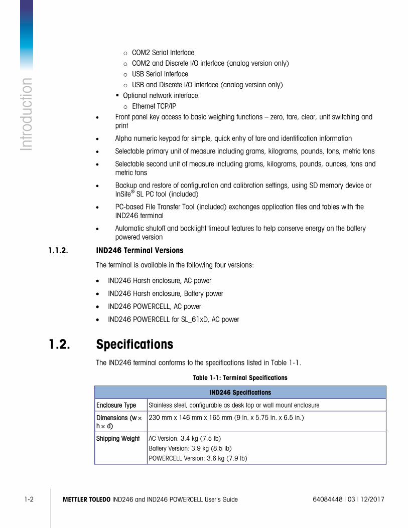
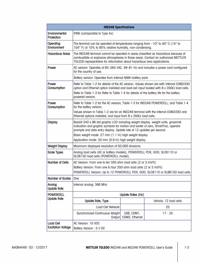
1.2. Specifications The IND246 terminal conforms to the specifications listed in Table 1-1.
Table 1-1: Terminal Specifications
IND246 Specifications
Enclosure Type Stainless steel, configurable as desk top or wall mount enclosure
Dimensions (w × h × d)
230 mm x 146 mm x 165 mm (9 in. x 5.75 in. x 6.5 in.)
Shipping Weight AC Version: 3.4 kg (7.5 lb)
Battery Version: 3.9 kg (8.5 lb)
POWERCELL Version: 3.6 kg (7.9 lb)
64084448 | 03 | 12/2017 METTLER TOLEDO IND246 and IND246 POWERCELL User's Guide 1-3
IND246 Specifications
Environmental Protection
IP66 (comparable to Type 4x)
Operating Environment
The terminal can be operated at temperatures ranging from −10° to 40° C (14° to 104° F) at 10% to 95% relative humidity, non-condensing.
Hazardous Areas The IND246 terminal cannot be operated in areas classified as Hazardous because of combustible or explosive atmospheres in those areas. Contact an authorized METTLER TOLEDO representative for information about hazardous area applications.
Power AC version: Operates at 85–264 VAC, 49–61 Hz and includes a power cord configured for the country of use.
Battery version: Operates from internal NiMH battery pack
Power Consumption
Refer to Table 1-2 for details of the AC version. Values shown are with internal COM2/DIO option and Ethernet option installed and load cell input loaded with 8 x 350Ω load cells.
Refer to Table 1-3 for Refer to Table 1-4 for details of the battery life for the battery powered version.
Power Consumption
Refer to Table 1-2 for the AC version; Table 1-3 for IND246 POWERCELL; and Table 1-4 for the battery version.
Values shown in Table 1-2 are for an IND246 terminal with the internal COM2/DIO and Ethernet options installed, and input from 8 x 350Ω load cells.
Display Backlit 240 x 96 dot graphic LCD including weight display, weight units, gross/net indication and graphic symbols for motion and center of zero, SmartTrac, operator prompts and data entry display. Update rate of 12 updates per second.
Basic weight mode: 27 mm (1.1 in) high weight display
Application mode: 20 mm (0.8 in) high weight display
Weight Display Maximum displayed resolution of 50,000 divisions.
Scale Types Analog load cells (AC or battery models), POWERCELL PDX, GDD, SLC611D or SLD615D load cells (POWERCELL model),
Number of Cells AC Version: From one to ten 350-ohm load cells (2 or 3 mV/V)
Battery Version: From one to four 350-ohm load cells (2 or 3 mV/V)
POWERCELL Version: Up to 12 POWERCELL PDX, GDD, SLC611D or SLB615D load cells
Number of Scales One
Analog Update Rate
Internal analog: 366 MHz
POWERCELL Update Rate
Update Rates (Hz)
Update Rate, Type Vehicle, 12 load cells
Load Cell Network 25
Synchronized Continuous Weight Output
USB, COM1, COM2, Ethernet
17 - 25
Load Cell Excitation Voltage
AC Version: 10 VDC
Battery Version : 5 V DC
1-4 METTLER TOLEDO IND246 and IND246 POWERCELL User's Guide 64084448 | 03 | 12/2017
Intro
duct
ion
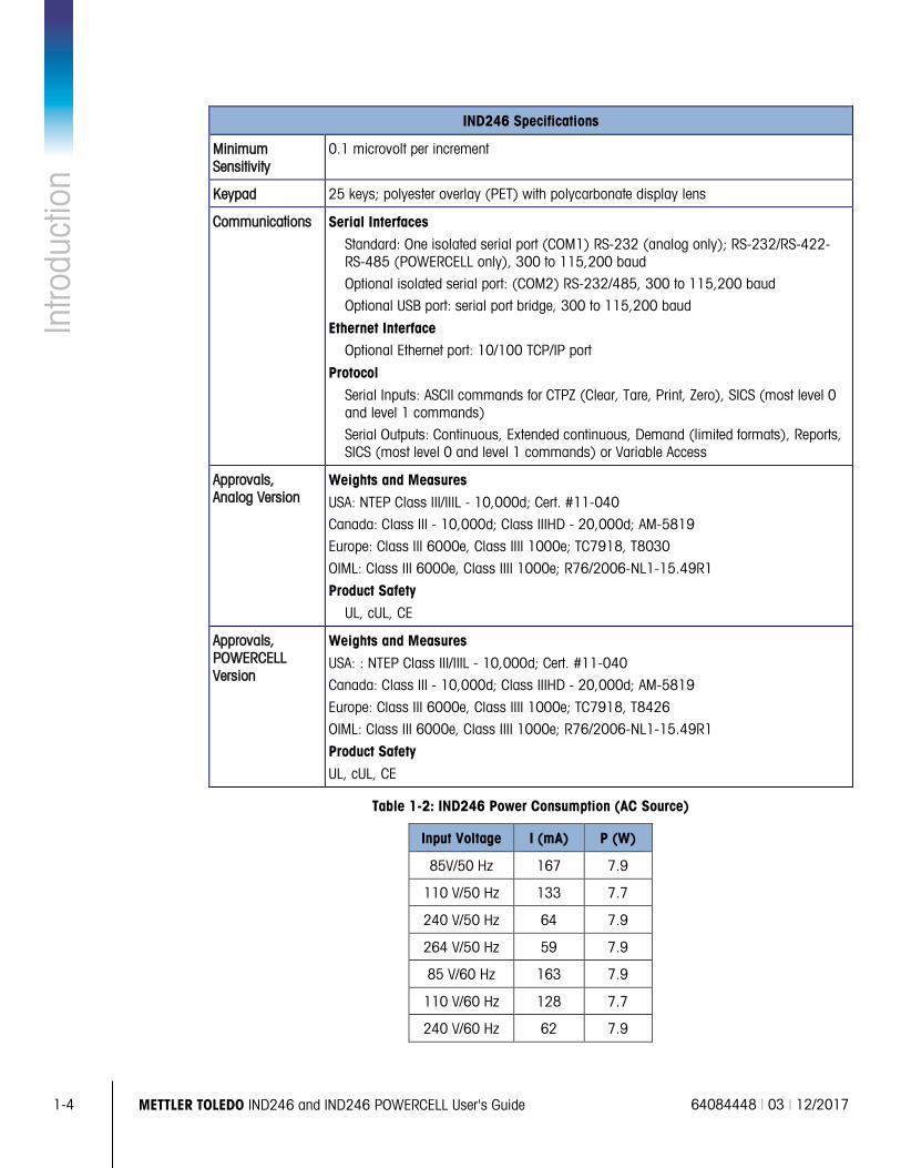
IND246 Specifications
Minimum Sensitivity
0.1 microvolt per increment
Keypad 25 keys; polyester overlay (PET) with polycarbonate display lens
Communications Serial Interfaces
Standard: One isolated serial port (COM1) RS-232 (analog only); RS-232/RS-422-RS-485 (POWERCELL only), 300 to 115,200 baud
Optional isolated serial port: (COM2) RS-232/485, 300 to 115,200 baud
Optional USB port: serial port bridge, 300 to 115,200 baud
Ethernet Interface Optional Ethernet port: 10/100 TCP/IP port
Protocol Serial Inputs: ASCII commands for CTPZ (Clear, Tare, Print, Zero), SICS (most level 0 and level 1 commands)
Serial Outputs: Continuous, Extended continuous, Demand (limited formats), Reports, SICS (most level 0 and level 1 commands) or Variable Access
Approvals, Analog Version
Weights and Measures
USA: NTEP Class III/IIIL - 10,000d; Cert. #11-040
Canada: Class III - 10,000d; Class IIIHD - 20,000d; AM-5819
Europe: Class III 6000e, Class IIII 1000e; TC7918, T8030
OIML: Class III 6000e, Class IIII 1000e; R76/2006-NL1-15.49R1
Product Safety
UL, cUL, CE
Approvals, POWERCELL Version
Weights and Measures
USA: : NTEP Class III/IIIL - 10,000d; Cert. #11-040
Canada: Class III - 10,000d; Class IIIHD - 20,000d; AM-5819
Europe: Class III 6000e, Class IIII 1000e; TC7918, T8426
OIML: Class III 6000e, Class IIII 1000e; R76/2006-NL1-15.49R1
Product Safety
UL, cUL, CE
Table 1-2: IND246 Power Consumption (AC Source)
Input Voltage I (mA) P (W)
85V/50 Hz 167 7.9
110 V/50 Hz 133 7.7
240 V/50 Hz 64 7.9
264 V/50 Hz 59 7.9
85 V/60 Hz 163 7.9
110 V/60 Hz 128 7.7
240 V/60 Hz 62 7.9
64084448 | 03 | 12/2017 METTLER TOLEDO IND246 and IND246 POWERCELL User's Guide 1-5
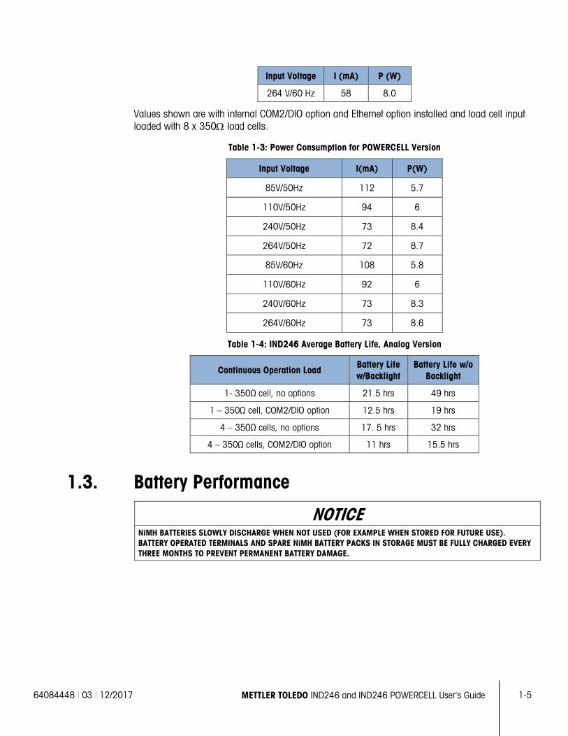
Input Voltage I (mA) P (W)
264 V/60 Hz 58 8.0
Values shown are with internal COM2/DIO option and Ethernet option installed and load cell input loaded with 8 x 350Ω load cells.
Table 1-3: Power Consumption for POWERCELL Version
Input Voltage I(mA) P(W)
85V/50Hz 112 5.7
110V/50Hz 94 6
240V/50Hz 73 8.4
264V/50Hz 72 8.7
85V/60Hz 108 5.8
110V/60Hz 92 6
240V/60Hz 73 8.3
264V/60Hz 73 8.6
Table 1-4: IND246 Average Battery Life, Analog Version
Continuous Operation Load Battery Life w/Backlight
Battery Life w/o Backlight
1- 350Ω cell, no options 21.5 hrs 49 hrs
1 – 350Ω cell, COM2/DIO option 12.5 hrs 19 hrs
4 – 350Ω cells, no options 17. 5 hrs 32 hrs
4 – 350Ω cells, COM2/DIO option 11 hrs 15.5 hrs
1.3. Battery Performance
NOTICE NiMH BATTERIES SLOWLY DISCHARGE WHEN NOT USED (FOR EXAMPLE WHEN STORED FOR FUTURE USE). BATTERY OPERATED TERMINALS AND SPARE NiMH BATTERY PACKS IN STORAGE MUST BE FULLY CHARGED EVERY THREE MONTHS TO PREVENT PERMANENT BATTERY DAMAGE.
1-6 METTLER TOLEDO IND246 and IND246 POWERCELL User's Guide 64084448 | 03 | 12/2017
Intro
duct
ion
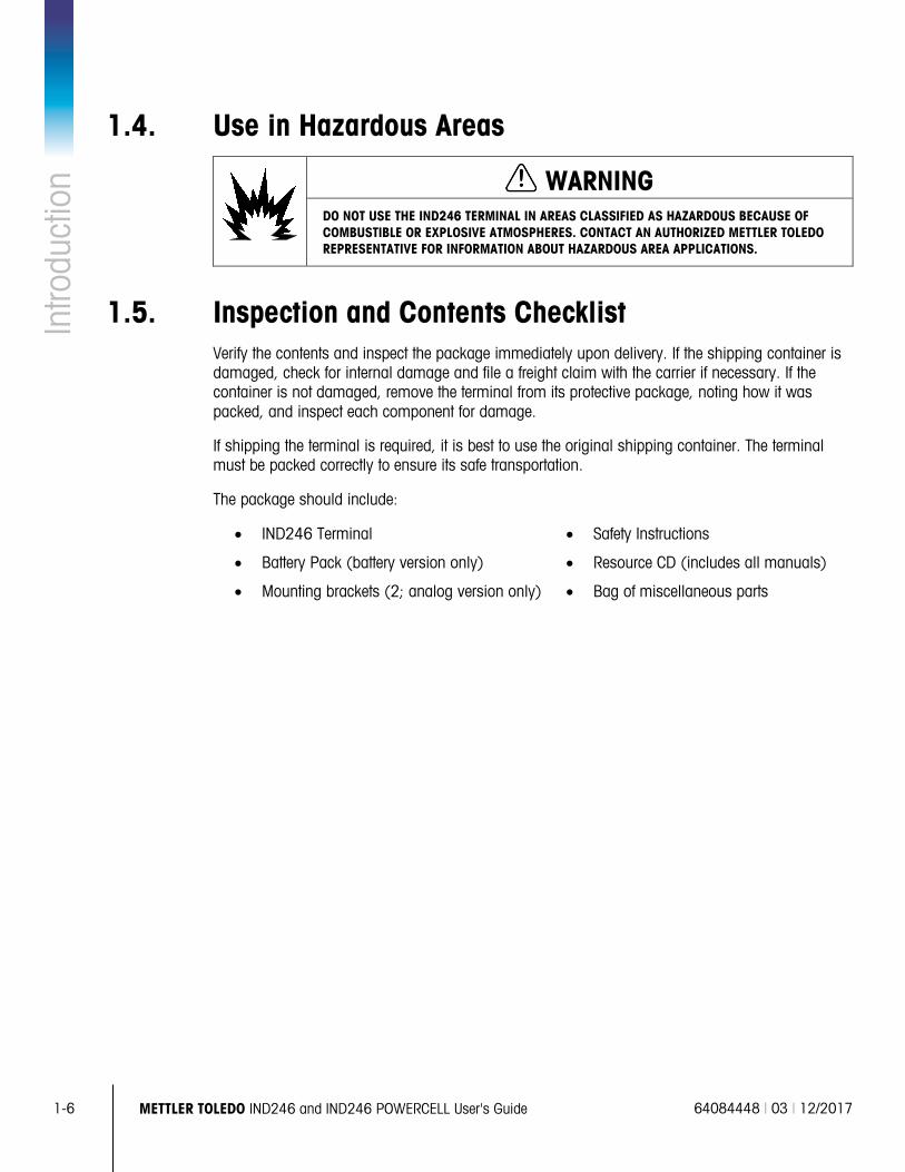
1.4. Use in Hazardous Areas
WARNING DO NOT USE THE IND246 TERMINAL IN AREAS CLASSIFIED AS HAZARDOUS BECAUSE OF COMBUSTIBLE OR EXPLOSIVE ATMOSPHERES. CONTACT AN AUTHORIZED METTLER TOLEDO REPRESENTATIVE FOR INFORMATION ABOUT HAZARDOUS AREA APPLICATIONS.
1.5. Inspection and Contents Checklist Verify the contents and inspect the package immediately upon delivery. If the shipping container is damaged, check for internal damage and file a freight claim with the carrier if necessary. If the container is not damaged, remove the terminal from its protective package, noting how it was packed, and inspect each component for damage.
If shipping the terminal is required, it is best to use the original shipping container. The terminal must be packed correctly to ensure its safe transportation.
The package should include:
• IND246 Terminal
• Battery Pack (battery version only)
• Mounting brackets (2; analog version only)
• Safety Instructions
• Resource CD (includes all manuals)
• Bag of miscellaneous parts
64084448 | 03 | 12/2017 METTLER TOLEDO IND246 and IND246 POWERCELL User's Guide 1-7
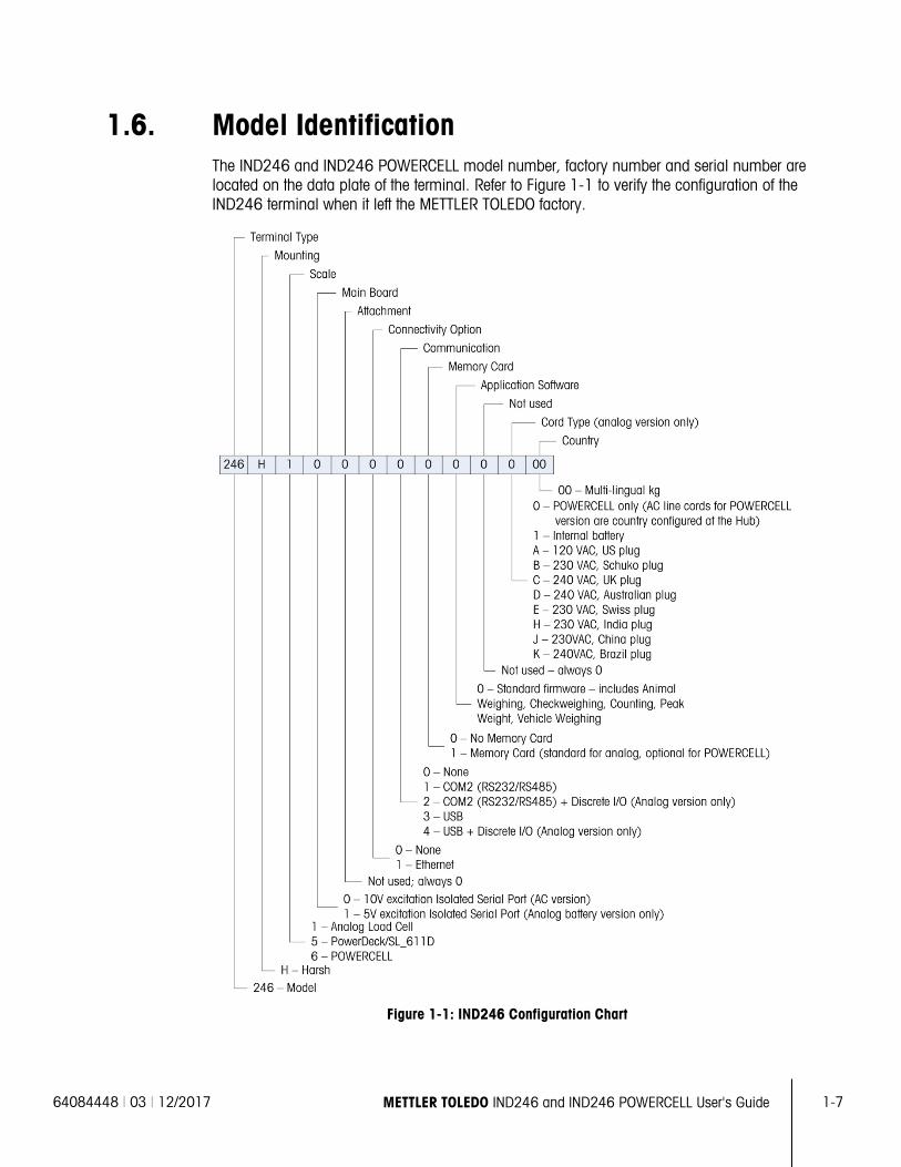
1.6. Model Identification The IND246 and IND246 POWERCELL model number, factory number and serial number are located on the data plate of the terminal. Refer to Figure 1-1 to verify the configuration of the IND246 terminal when it left the METTLER TOLEDO factory.
Figure 1-1: IND246 Configuration Chart
1-8 METTLER TOLEDO IND246 and IND246 POWERCELL User's Guide 64084448 | 03 | 12/2017
Intro
duct
ion
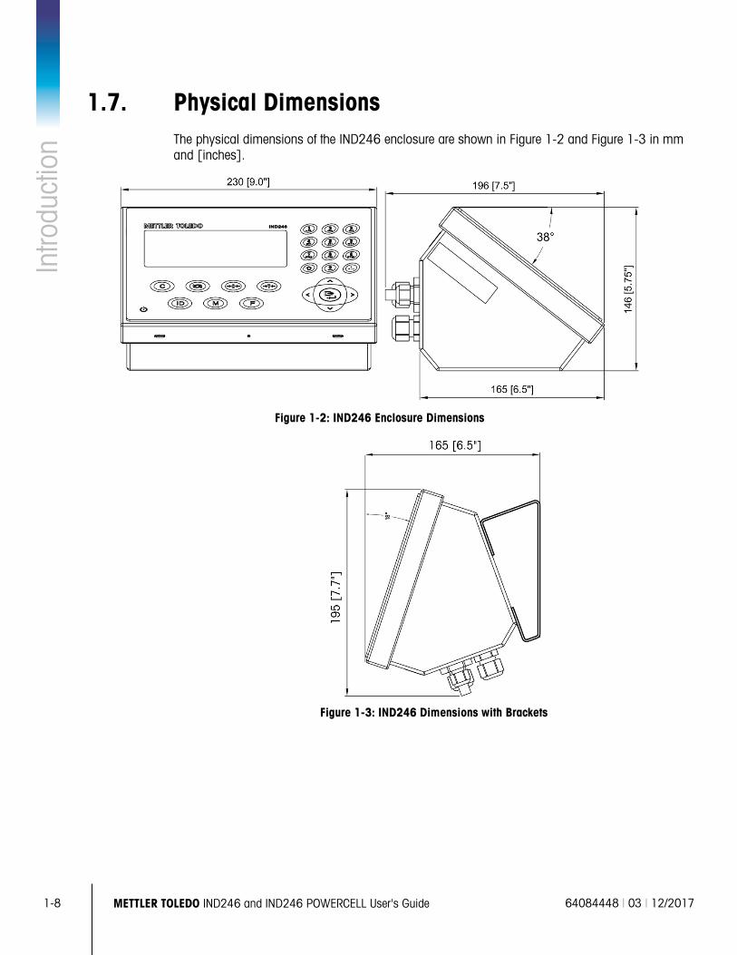
1.7. Physical Dimensions The physical dimensions of the IND246 enclosure are shown in Figure 1-2 and Figure 1-3 in mm and [inches].
Figure 1-2: IND246 Enclosure Dimensions
Figure 1-3: IND246 Dimensions with Brackets
64084448 | 03 | 12/2017 METTLER TOLEDO IND246 and IND246 POWERCELL User's Guide 1-9
1.8. Main PCB The IND246 terminal’s main printed circuit board (PCB) provides the analog load cell scale interface, as well as the COM1 RS-232 serial port. The IND246 POWERCELL main board provides the load cell interface and a standard COM1 RS-232/RS-422/RS-485 isolated serial port.
The main board also contains the power input connection (for either AC supply or battery, depending on the model), display interface, keypad interface and six-position DIP switch.
An SD memory card socket is mounted to the PCB to support the optional SD memory and bus connectors are included for the option boards.
1.8.1. SD Memory
An SD Memory card is included as a standard feature of the analog version of the IND246, and is available as an option for the POWERCELL version. The card provides a medium on which to store files such as Alibi memory, transaction records in the vehicle application, IDs in the counting application and target weights in the checkweighing application.
The SD memory can be used to extract and save the configuration and calibration settings of the terminal. These can then be restored to the terminal or loaded to a different terminal.
1.9. Scale Bases 1.9.1. Analog
The standard IND246 terminal supports analog scale bases and provides either 10 volts (AC version) or 5 volts (battery version) of excitation to drive analog load cells. Up to four (battery version) or ten (AC version) 350Ω load cells can be powered by the terminal.
A six wire load cell connection is provided with sense lines to help maintain accuracy as the load cell cable resistance changes with temperature variations.
1.9.2. POWERCELL
The IND246 POWERCELL terminal supports scale bases that use POWERCELL PDX, GDD, SLC611D or SLB615D load cells. Up to 12 load cells can be configured in a single scale platform. The load cell network provides monitoring and logging of a variety of factors that can affect system integrity, including weighing errors, overloads and network health. The specific characteristics differ by type of load cell.
1-10 METTLER TOLEDO IND246 and IND246 POWERCELL User's Guide 64084448 | 03 | 12/2017
Intro
duct
ion
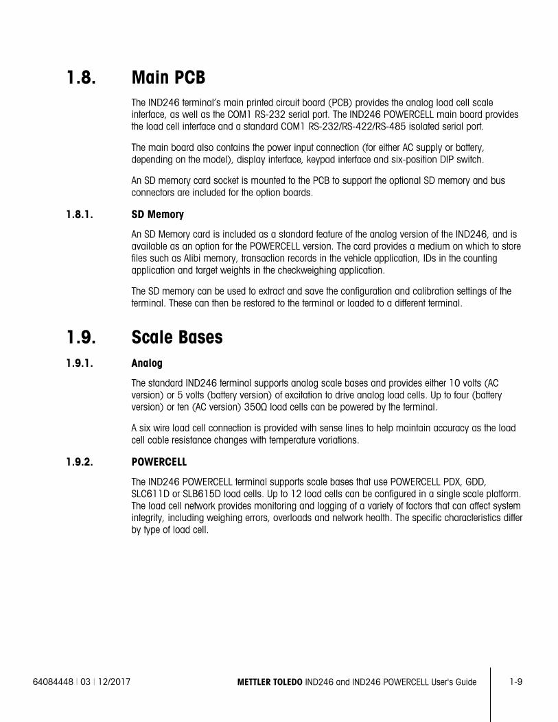
1.9.3. PowerDeck
The IND246 POWERCELL supports PowerDeckTM weighing platforms. These provide calibration without weights for fast installation and visual guidance for leveling the floor platform.
Figure 1-4: IND246 POWERCELL with PowerDeck Platform
1.10. Options The following options are available for all versions of the IND246:
• COM2 Serial Port
One RS-232/485 isolated serial COM port
• COM2 and DIO (relay output)
One RS-232/485 isolated serial COM port
Internal, discrete I/O (2 inputs and 4 outputs; supported in analog version only)
Inputs are optically isolated solid state and switch selectable as either active or passive
Output relays provide one normally open contact per relay
• USB Port
One USB 2.0 compliant port, hardware bridge. Acts as virtual (UCP) COM port
• USB and DIO (relay output)
One USB 2.0 compliant port, hardware bridge. Acts as virtual (UCP) COM port
Internal, discrete I/O (2 inputs and 4 outputs; supported in analog version only)
Inputs are optically isolated solid state and switch selectable as either active or passive
Output relays provide one normally open contact per relay
• Ethernet Port
One 10/100 Ethernet port with automatic link polarity detection and correction. Supports TCP/IP socket connection. Does not support FTP
1.10.1. COM2 Serial Port
This optional port provides RS-232 and RS-485 communication at rates from 300 to 115.2k baud. The port is bidirectional and can be configured for various functions such as demand output, continuous output, extended continuous output, SICS host communications or ASCII command input (C, T, P, Z).
64084448 | 03 | 12/2017 METTLER TOLEDO IND246 and IND246 POWERCELL User's Guide 1-11
The COM2 port is galvanically isolated for both RS-232 and RS-485, to provide surge voltage protection.
The RS-485 connection can be used as an RS-422 transmit only when sending continuous output to a scoreboard or remote display.
1.10.2. Discrete I/O
The Discrete I/O option is supported only in the analog version of the IND246.
The discrete I/O interface option provides dry-contact relay outputs. The relay contacts will switch up to 30 volts DC or 250 volts AC at 1A.
The inputs are switch selectable as either active (for simple pushbutton control) or passive (for connection to devices that supply their own power for the inputs).
1.10.3. USB
The USB port provided is a hardware bridge acting as a virtual COM port, and is used for conversion of serial data. The port is bidirectional and can be configured for various functions such as demand output, continuous output, extended continuous output, SICS host communications or ASCII command input (C, T, P, Z).
1.10.4. Ethernet
The IND246 Ethernet option provides an RJ45 jack for connection to an Ethernet network or host device. A TCP socket connection can be made to port 1701 to transfer files or to exchange data with a PC. This port can also operate as a print client to send data to a network printer.
1-12 METTLER TOLEDO IND246 and IND246 POWERCELL User's Guide 64084448 | 03 | 12/2017
Intro
duct
ion
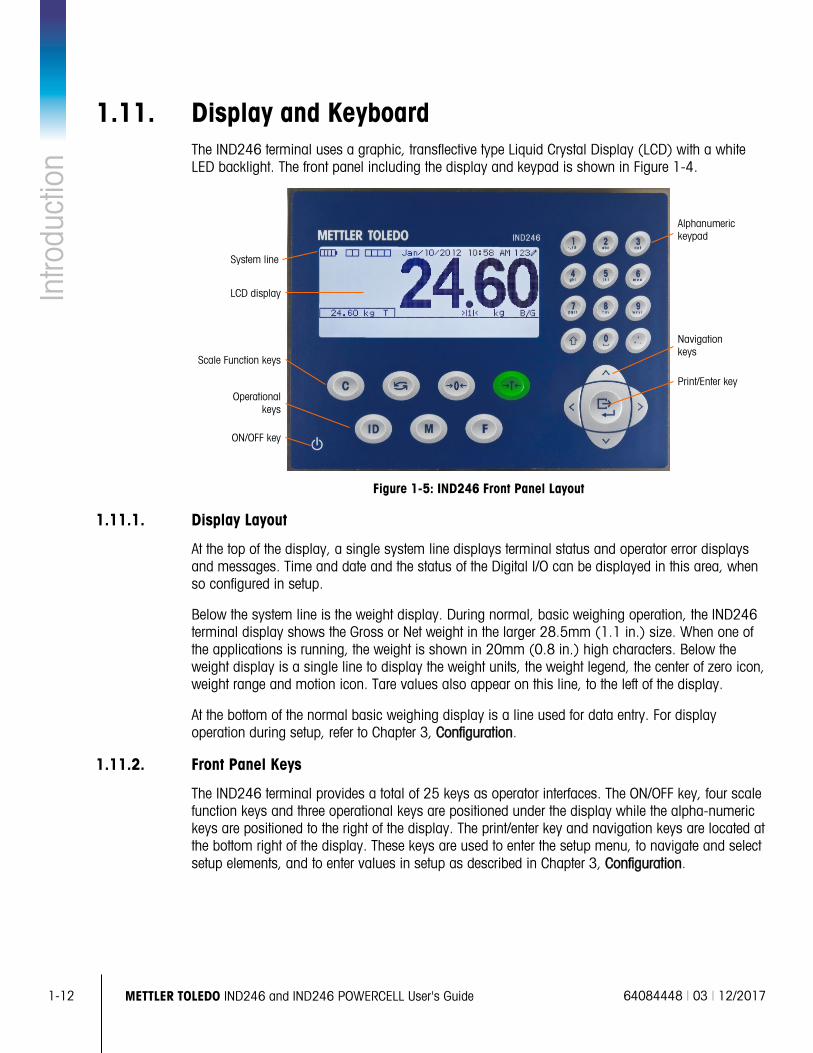
1.11. Display and Keyboard The IND246 terminal uses a graphic, transflective type Liquid Crystal Display (LCD) with a white LED backlight. The front panel including the display and keypad is shown in Figure 1-4.
Figure 1-5: IND246 Front Panel Layout
1.11.1. Display Layout
At the top of the display, a single system line displays terminal status and operator error displays and messages. Time and date and the status of the Digital I/O can be displayed in this area, when so configured in setup.
Below the system line is the weight display. During normal, basic weighing operation, the IND246 terminal display shows the Gross or Net weight in the larger 28.5mm (1.1 in.) size. When one of the applications is running, the weight is shown in 20mm (0.8 in.) high characters. Below the weight display is a single line to display the weight units, the weight legend, the center of zero icon, weight range and motion icon. Tare values also appear on this line, to the left of the display.
At the bottom of the normal basic weighing display is a line used for data entry. For display operation during setup, refer to Chapter 3, Configuration.
1.11.2. Front Panel Keys
The IND246 terminal provides a total of 25 keys as operator interfaces. The ON/OFF key, four scale function keys and three operational keys are positioned under the display while the alpha-numeric keys are positioned to the right of the display. The print/enter key and navigation keys are located at the bottom right of the display. These keys are used to enter the setup menu, to navigate and select setup elements, and to enter values in setup as described in Chapter 3, Configuration.
LCD display
Alphanumeric keypad
Scale Function keys
Print/Enter key
ON/OFF key
Navigation keys
Operational keys
System line
64084448 | 03 | 10/2017 METTLER TOLEDO IND246 and IND246 POWERCELL User's Guide 2-1
This chapter covers
• Overview
• Basic Functionality
• Display Operation
• Keypad Operation
• Operator Menu
• Applications
2 Operation: Terminal
2.1. Overview This chapter provides information about the basic functionality of the IND246 terminal, including display operation, keypad functions and menu navigation.
Operation of the terminal varies depending on which functions are enabled, and on the configuration of parameters in setup. Configuration is described in Chapter 3, Configuration: Terminal.
2.2. Display Elements and Keypad Operation Refer to Figure 1-4 for an over view of the layout of the front panel of the IND246.
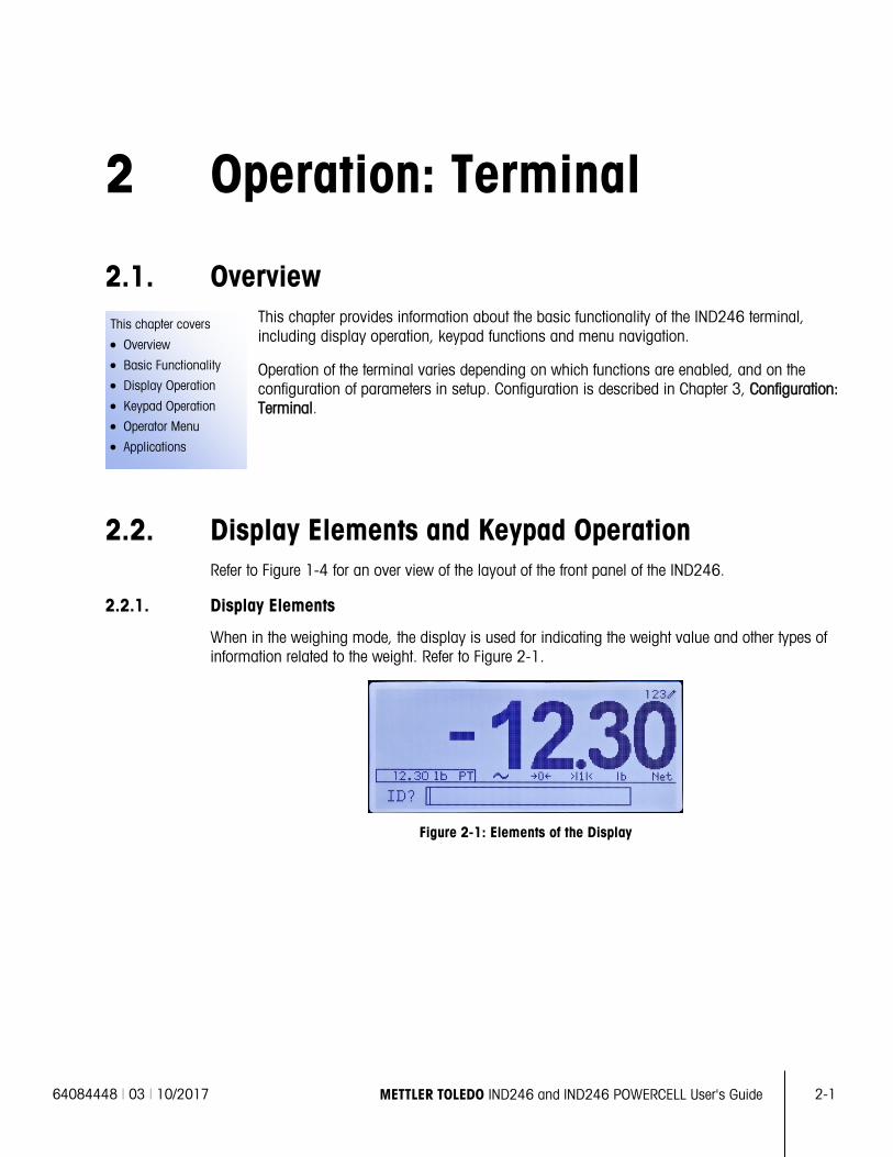
2.2.1. Display Elements
When in the weighing mode, the display is used for indicating the weight value and other types of information related to the weight. Refer to Figure 2-1.
Figure 2-1: Elements of the Display
2-2 METTLER TOLEDO IND246 and IND246 POWERCELL User's Guide 64084448 | 03 | 10/2017
Ope
ratio
n: T
erm
inal
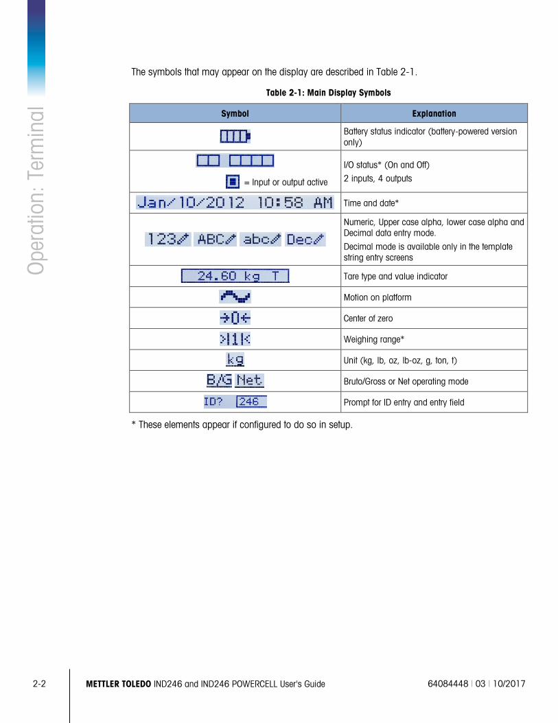
The symbols that may appear on the display are described in Table 2-1.
Table 2-1: Main Display Symbols
Symbol Explanation
Battery status indicator (battery-powered version only)
I/O status* (On and Off)
2 inputs, 4 outputs
= Input or output active
Time and date*
Numeric, Upper case alpha, lower case alpha and Decimal data entry mode.
Decimal mode is available only in the template string entry screens
Tare type and value indicator
Motion on platform
Center of zero
Weighing range*
Unit (kg, lb, oz, lb-oz, g, ton, t)
Bruto/Gross or Net operating mode
Prompt for ID entry and entry field
* These elements appear if configured to do so in setup.
64084448 | 03 | 10/2017 METTLER TOLEDO IND246 and IND246 POWERCELL User's Guide 2-3
2.2.2. Keypad Operation
The front panel keys are used to operate and configure the IND246.
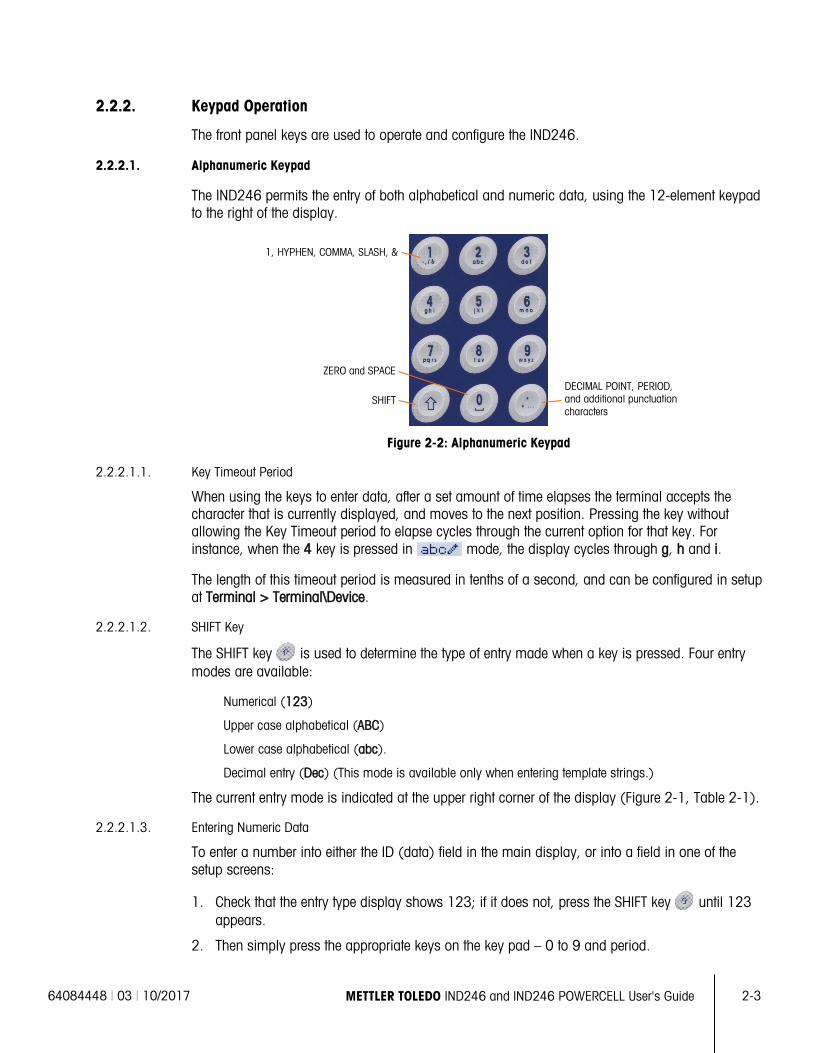
2.2.2.1. Alphanumeric Keypad
The IND246 permits the entry of both alphabetical and numeric data, using the 12-element keypad to the right of the display.
Figure 2-2: Alphanumeric Keypad
2.2.2.1.1. Key Timeout Period
When using the keys to enter data, after a set amount of time elapses the terminal accepts the character that is currently displayed, and moves to the next position. Pressing the key without allowing the Key Timeout period to elapse cycles through the current option for that key. For instance, when the 4 key is pressed in mode, the display cycles through g, h and i.
The length of this timeout period is measured in tenths of a second, and can be configured in setup at Terminal > Terminal\Device.
2.2.2.1.2. SHIFT Key
The SHIFT key is used to determine the type of entry made when a key is pressed. Four entry modes are available:
Numerical (123)
Upper case alphabetical (ABC)
Lower case alphabetical (abc).
Decimal entry (Dec) (This mode is available only when entering template strings.)
The current entry mode is indicated at the upper right corner of the display (Figure 2-1, Table 2-1).
2.2.2.1.3. Entering Numeric Data
To enter a number into either the ID (data) field in the main display, or into a field in one of the setup screens:
1. Check that the entry type display shows 123; if it does not, press the SHIFT key until 123 appears.
2. Then simply press the appropriate keys on the key pad – 0 to 9 and period.
SHIFT
ZERO and SPACE DECIMAL POINT, PERIOD, and additional punctuation characters
1, HYPHEN, COMMA, SLASH, &
2-4 METTLER TOLEDO IND246 and IND246 POWERCELL User's Guide 64084448 | 03 | 10/2017
Ope
ratio
n: T
erm
inal
Pressing a numeric key followed by TARE enters a manual tare value. Pressing the ID key shifts focus to the prompt line at the bottom left of the screen, and allows data entry there.
To delete one or more characters, press the CLEAR key.
2.2.2.1.4. Entering Alphanumeric Data
To enter an alphabetic character:
1. Press the SHIFT key to access the character type (lower or upper case)
2. Press the appropriate key until the correct character displays.
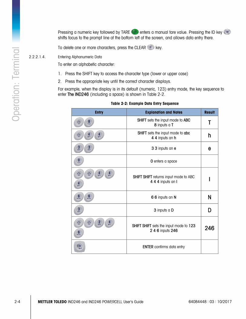
For example, when the display is in its default (numeric, 123) entry mode, the key sequence to enter The IND246 (including a space) is shown in Table 2-2.
Table 2-2: Example Data Entry Sequence
Entry Explanation and Notes Result
SHIFT sets the input mode to ABC 8 inputs a T T
SHIFT sets the input mode to abc 4 4 inputs an h h
3 3 inputs an e e
0 enters a space
SHIFT SHIFT returns input mode to ABC 4 4 4 inputs an I I
6 6 inputs an N N
3 inputs a D D
SHIFT SHIFT sets the input mode to 123 2 4 6 inputs 246 246
ENTER confirms data entry
64084448 | 03 | 10/2017 METTLER TOLEDO IND246 and IND246 POWERCELL User's Guide 2-5
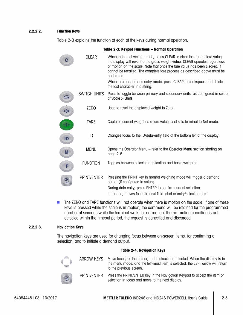
2.2.2.2. Function Keys
Table 2-3 explains the function of each of the keys during normal operation.
Table 2-3: Keypad Functions – Normal Operation
CLEAR When in the net weight mode, press CLEAR to clear the current tare value; the display will revert to the gross weight value. CLEAR operates regardless of motion on the scale. Note that once the tare value has been cleared, it cannot be recalled. The complete tare process as described above must be performed.
When in alphanumeric entry mode, press CLEAR to backspace and delete the last character in a string.
SWITCH UNITS Press to toggle between primary and secondary units, as configured in setup at Scale > Units.
ZERO Used to reset the displayed weight to Zero.
TARE Captures current weight as a tare value, and sets terminal to Net mode.
ID Changes focus to the ID/data-entry field at the bottom left of the display.
MENU Opens the Operator Menu – refer to the Operator Menu section starting on page 2-6.
FUNCTION Toggles between selected application and basic weighing.
PRINT/ENTER Pressing the PRINT key in normal weighing mode will trigger a demand output (if configured in setup)
During data entry, press ENTER to confirm current selection.
In menus, moves focus to next field label or entry/selection box.
The ZERO and TARE functions will not operate when there is motion on the scale. If one of these keys is pressed while the scale is in motion, the command will be retained for the programmed number of seconds while the terminal waits for no-motion. If a no-motion condition is not detected within the timeout period, the request is cancelled and discarded.
2.2.2.3. Navigation Keys
The navigation keys are used for changing focus between on-screen items, for confirming a selection, and to initiate a demand output.
Table 2-4: Navigation Keys
ARROW KEYS Move focus, or the cursor, in the direction indicated. When the display is in the menu mode, and the left-most item is selected, the LEFT arrow will return to the previous screen.
PRINT/ENTER Press the PRINT/ENTER key in the Navigation Keypad to accept the item or selection in focus and move to the next display.
2-6 METTLER TOLEDO IND246 and IND246 POWERCELL User's Guide 64084448 | 03 | 10/2017
Ope
ratio
n: T
erm
inal
2.3. Operator Menu There are a few functions that operators typically perform which are available in a top-level menu system in the IND246 terminal. These include access to Alibi Memory, setting time and date, adjusting contrast, viewing and resetting the transaction counter, viewing and clearing totals, expanding the displayed weight resolution by 10, and recalling information. An explanation of how to access these functions follows.
2.3.1. Language Selection – F Codes
Depending on the terminal’s language setup (at Terminal > Region > Language), parameter labels in the operator menu will appear as words (“Hour”) or as an F-code (“F3.3.2.1”).
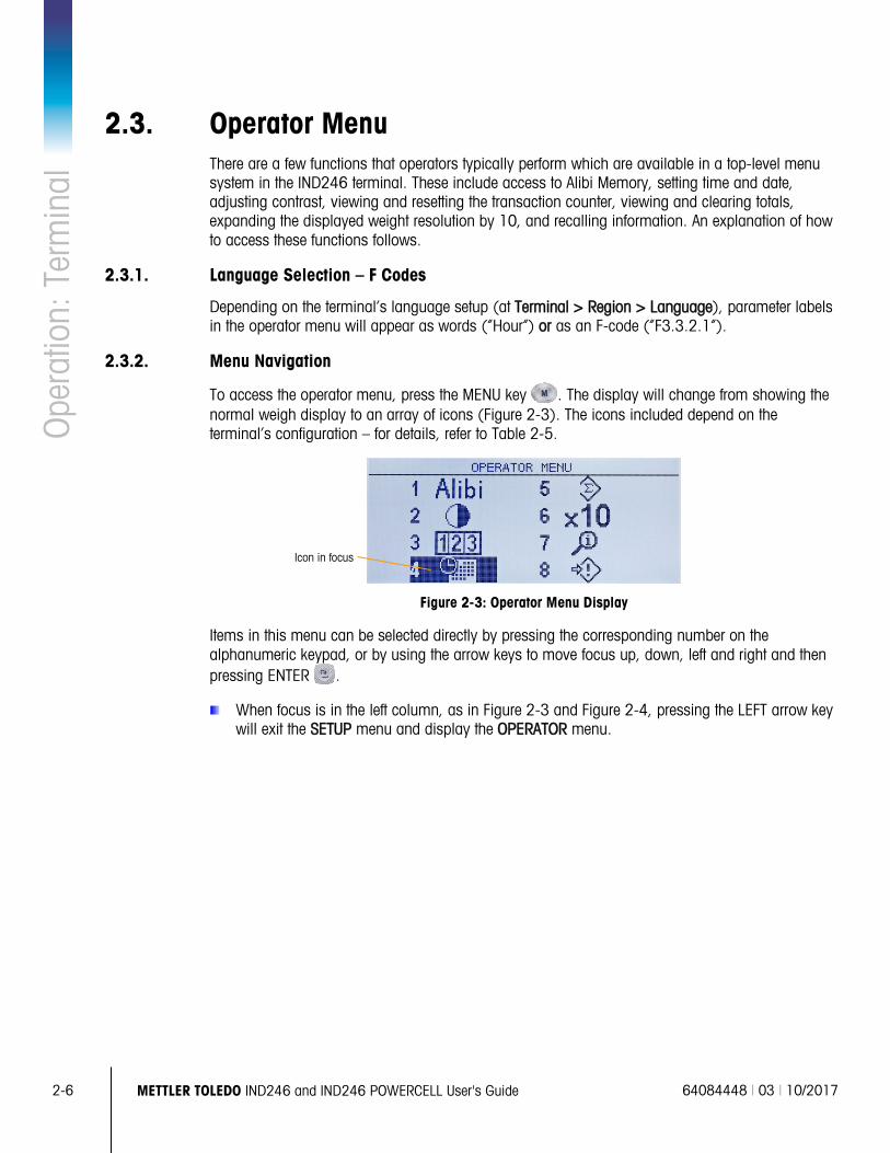
2.3.2. Menu Navigation
To access the operator menu, press the MENU key . The display will change from showing the normal weigh display to an array of icons (Figure 2-3). The icons included depend on the terminal’s configuration – for details, refer to Table 2-5.
Figure 2-3: Operator Menu Display
Items in this menu can be selected directly by pressing the corresponding number on the alphanumeric keypad, or by using the arrow keys to move focus up, down, left and right and then pressing ENTER .
When focus is in the left column, as in Figure 2-3 and Figure 2-4, pressing the LEFT arrow key will exit the SETUP menu and display the OPERATOR menu.
Icon in focus
64084448 | 03 | 10/2017 METTLER TOLEDO IND246 and IND246 POWERCELL User's Guide 2-7
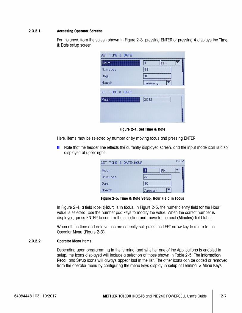
2.3.2.1. Accessing Operator Screens
For instance, from the screen shown in Figure 2-3, pressing ENTER or pressing 4 displays the Time & Date setup screen.
Figure 2-4: Set Time & Date
Here, items may be selected by number or by moving focus and pressing ENTER.
Note that the header line reflects the currently displayed screen, and the input mode icon is also displayed at upper right.
Figure 2-5: Time & Date Setup, Hour Field in Focus
In Figure 2-4, a field label (Hour) is in focus. In Figure 2-5, the numeric entry field for the Hour value is selected. Use the number pad keys to modify the value. When the correct number is displayed, press ENTER to confirm the selection and move to the next (Minutes) field label.
When all the time and date values are correctly set, press the LEFT arrow key to return to the Operator Menu (Figure 2-3).
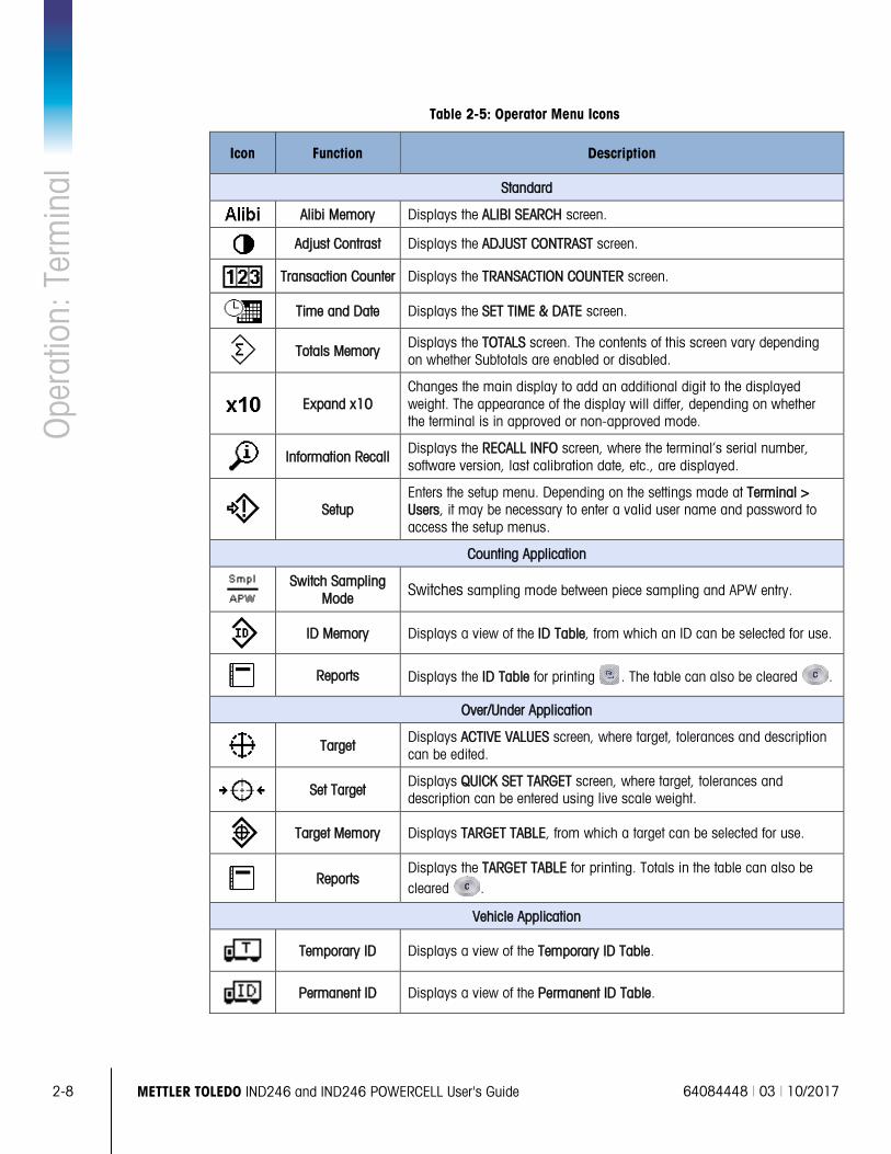
2.3.2.2. Operator Menu Items
Depending upon programming in the terminal and whether one of the Applications is enabled in setup, the icons displayed will include a selection of those shown in Table 2-5. The Information Recall and Setup icons will always appear last in the list. The other icons can be added or removed from the operator menu by configuring the menu keys display in setup at Terminal > Menu Keys.
2-8 METTLER TOLEDO IND246 and IND246 POWERCELL User's Guide 64084448 | 03 | 10/2017
Ope
ratio
n: T
erm
inal
Table 2-5: Operator Menu Icons
Icon Function Description
Standard
Alibi Memory Displays the ALIBI SEARCH screen.
Adjust Contrast Displays the ADJUST CONTRAST screen.
Transaction Counter Displays the TRANSACTION COUNTER screen.
Time and Date Displays the SET TIME & DATE screen.
Totals Memory Displays the TOTALS screen. The contents of this screen vary depending on whether Subtotals are enabled or disabled.
Expand x10 Changes the main display to add an additional digit to the displayed weight. The appearance of the display will differ, depending on whether the terminal is in approved or non-approved mode.
Information Recall Displays the RECALL INFO screen, where the terminal’s serial number, software version, last calibration date, etc., are displayed.
Setup Enters the setup menu. Depending on the settings made at Terminal > Users, it may be necessary to enter a valid user name and password to access the setup menus.
Counting Application
Switch Sampling Mode Switches sampling mode between piece sampling and APW entry.
ID Memory Displays a view of the ID Table, from which an ID can be selected for use.
Reports Displays the ID Table for printing . The table can also be cleared .
Over/Under Application
Target Displays ACTIVE VALUES screen, where target, tolerances and description can be edited.
Set Target Displays QUICK SET TARGET screen, where target, tolerances and description can be entered using live scale weight.
Target Memory Displays TARGET TABLE, from which a target can be selected for use.
Reports Displays the TARGET TABLE for printing. Totals in the table can also be cleared .
Vehicle Application
Temporary ID Displays a view of the Temporary ID Table.
Permanent ID Displays a view of the Permanent ID Table.
64084448 | 03 | 10/2017 METTLER TOLEDO IND246 and IND246 POWERCELL User's Guide 2-9
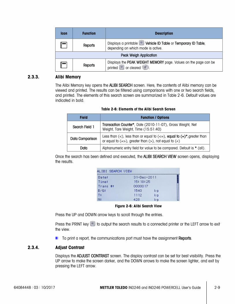
Icon Function Description
Reports Displays a printable Vehicle ID Table or Temporary ID Table, depending on which mode is active.
Peak Weigh Application
Reports Displays the PEAK WEIGHT MEMORY page. Values on the page can be printed or cleared .
2.3.3. Alibi Memory
The Alibi Memory key opens the ALIBI SEARCH screen. Here, the contents of Alibi memory can be viewed and printed. The results can be filtered using comparisons with one or two search fields, and printed. The elements of this search screen are summarized in Table 2-6. Default values are indicated in bold.
Table 2-6: Elements of the Alibi Search Screen
Field Function / Options
Search Field 1 Transaction Counter*, Date (2010-11-07), Gross Weight, Net Weight, Tare Weight, Time (15:51:40)
Data Comparison Less than (<), less than or equal to (<=), equal to (=)*,greater than or equal to (=>), greater than (>), not equal to (≠)
Data Alphanumeric entry field for value to be compared. Default is * (all).
Once the search has been defined and executed, the ALIBI SEARCH VIEW screen opens, displaying the results.
Figure 2-6: Alibi Search View
Press the UP and DOWN arrow keys to scroll through the entries.
Press the PRINT key to output the search results to a connected printer or the LEFT arrow to exit the view.
To print a report, the communications port must have the assignment Reports.
2.3.4. Adjust Contrast
Displays the ADJUST CONTRAST screen. The display contrast can be set for best visibility. Press the UP arrow to make the screen darker, and the DOWN arrows to make the screen lighter, and exit by pressing the LEFT arrow.
2-10 METTLER TOLEDO IND246 and IND246 POWERCELL User's Guide 64084448 | 03 | 10/2017
Ope
ratio
n: T
erm
inal
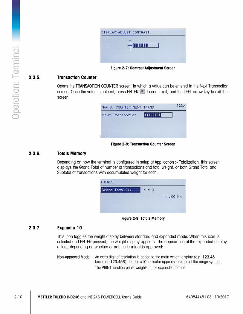
Figure 2-7: Contrast Adjustment Screen
2.3.5. Transaction Counter
Opens the TRANSACTION COUNTER screen, in which a value can be entered in the Next Transaction screen. Once the value is entered, press ENTER to confirm it, and the LEFT arrow key to exit the screen.
I
Figure 2-8: Transaction Counter Screen
2.3.6. Totals Memory
Depending on how the terminal is configured in setup at Application > Totalization, this screen displays the Grand Total of number of transactions and total weight, or both Grand Total and Subtotal of transactions with accumulated weight for each.
Figure 2-9: Totals Memory
2.3.7. Expand x 10
This icon toggles the weight display between standard and expanded mode. When this icon is selected and ENTER pressed, the weight display appears. The appearance of the expanded display differs, depending on whether or not the terminal is approved:
Non-Approved Mode An extra digit of resolution is added to the main weight display (e.g. 123.45 becomes 123.456) and the x10 indicator appears in place of the range symbol.
The PRINT function prints weights in the expanded format.
64084448 | 03 | 10/2017 METTLER TOLEDO IND246 and IND246 POWERCELL User's Guide 2-11
Approved Mode An extra digit of resolution is added to the main weight display, in a smaller size (e.g. 123.45 becomes 123.456). The range symbols operate normally.
The PRINT function is disabled.
2.3.8. Information Recall
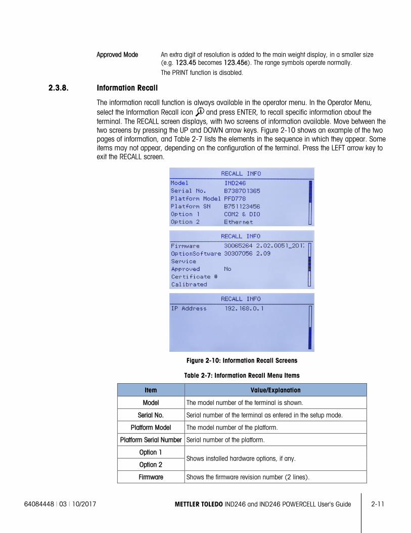
The information recall function is always available in the operator menu. In the Operator Menu, select the Information Recall icon and press ENTER, to recall specific information about the terminal. The RECALL screen displays, with two screens of information available. Move between the two screens by pressing the UP and DOWN arrow keys. Figure 2-10 shows an example of the two pages of information, and Table 2-7 lists the elements in the sequence in which they appear. Some items may not appear, depending on the configuration of the terminal. Press the LEFT arrow key to exit the RECALL screen.
Figure 2-10: Information Recall Screens
Table 2-7: Information Recall Menu Items
Item Value/Explanation
Model The model number of the terminal is shown.
Serial No. Serial number of the terminal as entered in the setup mode.
Platform Model The model number of the platform.
Platform Serial Number Serial number of the platform.
Option 1 Shows installed hardware options, if any.
Option 2
Firmware Shows the firmware revision number (2 lines).
2-12 METTLER TOLEDO IND246 and IND246 POWERCELL User's Guide 64084448 | 03 | 10/2017
Ope
ratio
n: T
erm
inal
Item Value/Explanation
Service A telephone number used to contact METTLER TOLEDO authorized service.
Approved Yes or No
Indicates whether the terminal has been programmed as Approved for use in legal for trade applications.
Certificate # Displays approval certificate number. An approval region must be selected to enable the display of the certificate number.
Calibrated Shows date of most recent calibration.
IP Address IP address assigned to the terminal. Shown only when the Ethernet option is installed.
2.3.9. Setup Access
The last icon displayed in the OPERATOR menu accesses the SETUP menu, from which all the terminal’s programming parameters can be viewed and modified. The settings and options available in setup are described in detail in Chapter 3, Configuration: Terminal.
It is not intended that operators enter the setup mode. After a weighing system is installed and is operational, it should not be necessary for an operator to access setup.
Note that a security password can be enabled in setup. When a password is set, it must be entered in order to access setup. This protects the setup parameters from inadvertent changes.
2.4. Basic Functionality This section provides information about IND246 basic functionality. Functions addressed in this section include:
• Zero • Clearing Tare • Information Recall
• Tare • Print • Target
Refer to Chapter 3, Configuration: Terminal, for further information about programming all the functionality described in this section.
2.4.1. Zero
The Zero function is used to set or reset the initial zero reference point of the terminal. There are three types of zero setting modes:
• Automatic Zero Maintenance
• Power Up Zero
• Pushbutton Zero
When the scale platform or weighbridge is empty, the terminal should indicate zero. The gross zero reference is recorded during calibration. If pushbutton zero is enabled in configuration and the weight is within the zero range pressing ZERO will capture a new gross zero reference point.
64084448 | 03 | 10/2017 METTLER TOLEDO IND246 and IND246 POWERCELL User's Guide 2-13
2.4.1.1. Automatic Zero Maintenance
Automatic Zero Maintenance (AZM) enables the IND246 to compensate for the build up of small amounts of weight and track itself back to the center of zero. Within the AZM operating range (selectable from 0.5, 1, 3 or 10 divisions), when the terminal is in a no motion condition, it makes small adjustments to the current zero reading to drive the weight reading toward the true center-of-zero. When the weight is outside of the programmed AZM range, this feature is not functional.
2.4.1.2. Power Up Zero
Power-Up Zero enables the IND246 terminal to capture a new zero reference point after power is applied. If there is motion during a power-up zero capture function, the terminal will continue to check for a no-motion condition until zero is captured.
Power-up zero can be disabled or enabled, and a range above and below calibrated zero can be configured. The range is programmable from 0% to 100% of capacity and can include a positive range and also a range below calibrated zero.
2.4.1.3. Pushbutton Zero
The pushbutton (semi-automatic) zero function can be accomplished by pressing the ZERO key , by programming a discrete input or by issuing a serial command.
The range for all types of semi-automatic zero is selectable (Disabled, 2% or 20%) plus or minus from the calibrated zero point.
Remote initiation of the semi-automatic Zero command is possible via a discrete input, or an ASCII ‘Z’ command sent serially (CPTZ and SICS interface modes).
2.4.2. Tare
Tare is the weight of an empty container. A tare value subtracts from the gross weight measurement, providing the computation of the net weight (material without the container). The tare function can also be used to track the net amount of material being added to or removed from a vessel or container. In this second case, the weight of the material in the container is included with the tare weight of the container and the display then reflects the net amount being added to or removed from the vessel.
Tare operations in the IND246 include:
• Pushbutton Tare • Net Sign Correction
• Keyboard (Preset) Tare • Automatic Tare
• Tare Clear — Manual Clear — Auto Clear
2.4.2.1. Pushbutton Tare
Pushbutton tare can be configured in setup as enabled or disabled. When disabled, pressing the TARE key has no effect.
2-14 METTLER TOLEDO IND246 and IND246 POWERCELL User's Guide 64084448 | 03 | 10/2017
Ope
ratio
n: T
erm
inal
If pushbutton tare is enabled, pressing the pushbutton TARE key initiates a semi-automatic tare. The IND246 will attempt to perform a tare process. If the process is successful, the display changes to a zero net weight indication and the previous weight on the scale is stored as the tare value. The net mode will be indicated on the display.
Several conditions could inhibit the pushbutton tare function:
Motion – Pushbutton tare cannot be taken when the scale is in motion. If motion is detected when a pushbutton tare command is received, the IND246 will wait for a programmed amount of time (the default value is 3 seconds) for a no-motion condition. If a stable (no motion) weight condition occurs before the timeout expires, the pushbutton tare command is executed.
If there is still motion at the end of the timeout, the command is aborted.
Pushbutton Tare Disabled – If pushbutton tare is configured as disabled, the TARE scale function key will not initiate a semi-automatic tare.
Negative Gross Weight – Any pushbutton tare attempted when the gross weight is at or below zero is ignored. Ensure that the gross weight is above zero.
2.4.2.2. Keyboard Tare
A keyboard (preset) tare is a numeric tare that is entered manually through the numeric keypad or received serially from a peripheral. The preset tare value cannot exceed the capacity of the scale. Data entered is interpreted to have the same units as the current displayed value. Motion does not affect the entry of preset tare values.
Keyboard tare can be configured in setup as enabled or disabled. When disabled, the numeric keypad and the TARE scale function key cannot be used to obtain a tare.
To enter a preset tare value manually, use the numeric keypad to enter the tare value (the data entered will display in the weight legend if keyboard tare is enabled in setup at Scale > Tare > Types) and press the TARE scale function key .
If configured in setup, remote equipment can enter a preset tare value using a serial command
If the preset tare is successful, the display changes to a net weight indication.
Several conditions could inhibit the preset tare function:
• Keyboard Tare Disabled – If keyboard tare is configured in setup as disabled, the numeric keypad and the TARE scale function key cannot be used to obtain a tare.
• Over-Capacity or Under-Zero Conditions – Preset tare is not allowed when the weight display indicates over capacity or under zero conditions. Any preset tare attempted when the scale is over capacity is ignored and a “Tare Failed–Over Cap” error displays. Any preset tare attempted when the weight display indicates an under zero condition is ignored and a “Tare Failed–Too Small” error displays.
A preset tare can be entered in free format. If the entered value does not match the displayed weight decimal point location or display interval, the entered tare value is rounded to the nearest display interval and the decimal point adjusted to match the gross weight. The rounding method is that 0.5
64084448 | 03 | 10/2017 METTLER TOLEDO IND246 and IND246 POWERCELL User's Guide 2-15
or more of a display interval (d) is increased to the next display interval and 0.49 or less of a display interval is decreased to the next lower display interval.
When entering a preset tare value less than 1.0, the operator can enter the data without the leading zero (left of the decimal point), but all subsequent display, storage, or printing of this value will include the leading zero. For example, a preset tare entry of .05 will display as 0.05.
If a preset tare has already been established and another preset tare is entered, the second preset tare replaces the previous value (it does not add to the previous value). The replacement tare can be larger or smaller than the original tare value.
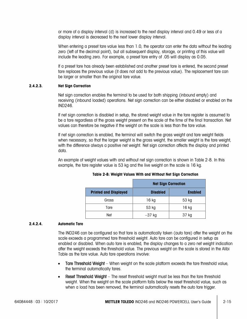
2.4.2.3. Net Sign Correction
Net sign correction enables the terminal to be used for both shipping (inbound empty) and receiving (inbound loaded) operations. Net sign correction can be either disabled or enabled on the IND246.
If net sign correction is disabled in setup, the stored weight value in the tare register is assumed to be a tare regardless of the gross weight present on the scale at the time of the final transaction. Net values can therefore be negative if the weight on the scale is less than the tare value.
If net sign correction is enabled, the terminal will switch the gross weight and tare weight fields when necessary, so that the larger weight is the gross weight, the smaller weight is the tare weight, with the difference always a positive net weight. Net sign correction affects the display and printed data.
An example of weight values with and without net sign correction is shown in Table 2-8. In this example, the tare register value is 53 kg and the live weight on the scale is 16 kg.
Table 2-8: Weight Values With and Without Net Sign Correction
Net Sign Correction
Printed and Displayed Disabled Enabled
Gross 16 kg 53 kg
Tare 53 kg 16 kg
Net −37 kg 37 kg
2.4.2.4. Automatic Tare
The IND246 can be configured so that tare is automatically taken (auto tare) after the weight on the scale exceeds a programmed tare threshold weight. Auto tare can be configured in setup as enabled or disabled. When auto tare is enabled, the display changes to a zero net weight indication after the weight exceeds the threshold value. The previous weight on the scale is stored in the Alibi Table as the tare value. Auto tare operations involve:
• Tare Threshold Weight – When weight on the scale platform exceeds the tare threshold value, the terminal automatically tares.
• Reset Threshold Weight – The reset threshold weight must be less than the tare threshold weight. When the weight on the scale platform falls below the reset threshold value, such as when a load has been removed, the terminal automatically resets the auto tare trigger.
2-16 METTLER TOLEDO IND246 and IND246 POWERCELL User's Guide 64084448 | 03 | 10/2017
Ope
ratio
n: T
erm
inal
• Motion Check – A motion check is provided to control the re-arming of the auto tare function. If
disabled, the auto tare trigger will be reset as soon as the weight falls below the reset value. If enabled, the weight must settle to no-motion below the reset threshold before the next auto tare can be initiated.
Several conditions could inhibit the auto tare function:
• Motion – Auto tare cannot be taken when the scale is in motion. If motion is detected after the weight on the scale exceeds a preset tare threshold weight, the IND246 will wait for a no-motion condition. If a stable (no motion) weight condition occurs within three seconds, the auto tare command is executed.
• Auto Tare Disabled – Auto tare can be configured in setup as enabled or disabled.
2.4.2.5. Clearing Tare
Tare values can be cleared manually or automatically.
2.4.2.5.1. Manual Clear
Manually clear tare values by pressing the CLEAR key on the numeric keypad when the IND246 is in the net mode and has completed the weighing operation. Motion on the scale will not impact a manual clear.
If configured in setup, pressing the ZERO scale function key will first clear the tare, then issue a zero command (see Chapter 3, Configuration: Terminal, the Scale section, Auto Clear).
2.4.2.5.2. Auto Clear
The IND246 can be configured to clear tare automatically when the weight returns to a value below a programmable threshold, or when a print command is issued. Once the tare is cleared, the display returns to the gross weighing mode.
Auto clear is disabled or enabled in setup. If auto clear is enabled the following parameters, configured in setup, affect the auto clear operation:
• Clear Threshold Weight – The clear threshold weight is the gross weight value below which the IND246 will automatically clear a tare after settling to a value above this threshold value.
• Motion Check – A motion check is provided to control the automatic clearing of tare. If the motion check is disabled, the tare value is cleared as soon as the weight drops below the threshold weight (auto clear threshold), regardless of the motion status.
• If the motion check is enabled, after meeting the requirements for weight value above and then below the threshold weight (auto clear threshold), the IND246 waits for a no-motion condition before automatically clearing the tare.
• Clear After Print – If enabled, tare is automatically cleared and the scale returned to the gross mode after data has been transmitted by pressing the ENTER/PRINT key or from a remote source.
Refer to the Scale, Auto Clear section of Chapter 3, Configuration: Terminal, for further information about configuring auto clear.
64084448 | 03 | 10/2017 METTLER TOLEDO IND246 and IND246 POWERCELL User's Guide 2-17
2.4.3. Unit Switching
In order to support locations and applications that utilize multiple measurement units, the IND246 supports unit switching. The SWITCH UNITS key enables switching between primary units (the main unit of measure) and alternate units.
When the SWITCH UNITS key is pressed, the display changes from the primary unit to the second unit. When this softkey is pressed again, the display returns to the primary unit. Each subsequent time the SWITCH UNITS key is pressed the IND246 continues to switch the unit.
When units are switched, the units value changes to the correspondingly selected units, and the conversion of the display value occurs. The display division changes to an equivalent weight value in the switched unit (for example, from 0.02 lb to 0.01 kg) and the decimal location switches to accommodate the conversion.
When switching units, the capacity of the converted units is dictated by the original number of divisions established in the capacity and increments area of setup. In some situations, this may reduce the capacity of the terminal when converting to second unit.
2.4.4. Expand By 10
The Expand by 10 icon appears in the OPERATOR menu (Figure 2-3), if so configured. It used to increase the selected weight display resolution by one additional digit. For example, a weight display of 40.96 could increase by one additional digit to display as 40.958. The Expand By Ten mode is indicated on the display by x10, which displays below the weight display. When Expand by Ten is selected again, the display reverts to the normal display of weight.
If programmed as approved with the metrology switch (SW1-1) ON, the Expand by Ten mode is displayed for five seconds then automatically returns to normal resolution. Printing is disabled when the weight is expanded and the terminal is programmed as approved.
2.4.5. Print
The print function (demand print) can be initiated by pressing the ENTER/PRINT key or by automatic print settings. Demand printing of data may also be initiated as part of a particular sequence of operation or special application software.
2.4.5.1. Print Interlock
Print Interlock is designed to enforce a single print output per transaction. Print Interlock can be disabled or enabled. If enabled, the print command is ignored until the measured gross weight exceeds the print interlock threshold. A print command initiated before the measured gross weight exceeds the print interlock threshold returns a Command failed – scale not ready error in the system line.
After the first print command is executed, subsequent print commands are ignored until the gross weight indication falls below the print interlock reset threshold. If a print command is blocked by print Interlock, a Command failed – scale not ready message appears in the system line.
2-18 METTLER TOLEDO IND246 and IND246 POWERCELL User's Guide 64084448 | 03 | 10/2017
Ope
ratio
n: T
erm
inal
2.4.5.2. Automatic Print
Automatic initiation of a demand print occurs after the gross weight exceeds the minimum threshold and there is no motion on the scale. After initiation, the gross weight must return below the reset threshold before a subsequent automatic print can occur.
Automatic print may be disabled or enabled. Automatic print can be triggered and reset by weight exceeding thresholds or by weight deviation from a previously stable reading.
2.4.6. Information Recall
A limited number of data fields are made available for easy recall on the terminal display. These fields include data such as model, serial number, identification fields, hardware and software configuration, a service contact phone number and whether the terminal has been set up as approved for legal for trade operation.
All this data is accessible under the Information Recall icon in the OPERATOR menu.
2.4.7. ID Entry
The ID function is used for two different purposes, depending on whether the terminal is in basic weighing mode or in one of the application modes.
• In basic weighing mode, a single ID field is available for transaction identification purposes, and the ID value will be shown at the bottom left of the display. The ID may also be included as a print field in any of the print templates.
• When the terminal is running one of the applications, the ID key may access records from an application table.
The basic weighing transactional ID value can be entered using one of two methods, described below.
2.4.7.1. Pressing the ID key first
Press the ID key . An "ID?" prompt will appear at the bottom of the display, with an entry box to its right.
Using the alphanumeric keypad, enter the desired ID value and then press ENTER. The ID value will be shown at the bottom left of the display and will be available for printing.
To clear the ID field, press the ID key and when the previous ID value is displayed in focus in the entry box, press the CLEAR key .
2.4.7.2. Pressing the ID key last
Begin to enter the desired ID value using the alpha-numeric keypad. A “Data:” prompt will appear at the bottom of the display, with an entry box to its right. As keys are pressed, the entered data will be displayed inside the entry box.
When the complete ID has been entered, press the ID key to terminate the entry. The ID value will be shown at the bottom left of the display and will be available for printing.
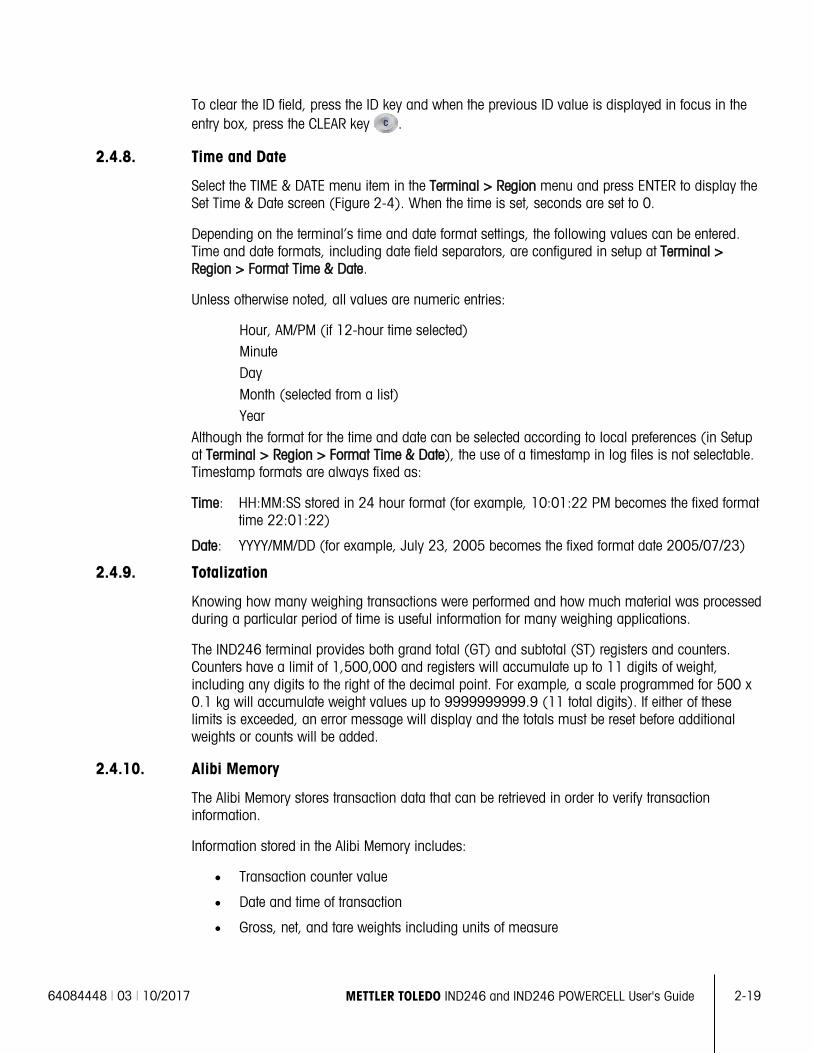
64084448 | 03 | 10/2017 METTLER TOLEDO IND246 and IND246 POWERCELL User's Guide 2-19
To clear the ID field, press the ID key and when the previous ID value is displayed in focus in the entry box, press the CLEAR key .
2.4.8. Time and Date
Select the TIME & DATE menu item in the Terminal > Region menu and press ENTER to display the Set Time & Date screen (Figure 2-4). When the time is set, seconds are set to 0.
Depending on the terminal’s time and date format settings, the following values can be entered. Time and date formats, including date field separators, are configured in setup at Terminal > Region > Format Time & Date.
Unless otherwise noted, all values are numeric entries:
Hour, AM/PM (if 12-hour time selected) Minute Day Month (selected from a list) Year
Although the format for the time and date can be selected according to local preferences (in Setup at Terminal > Region > Format Time & Date), the use of a timestamp in log files is not selectable. Timestamp formats are always fixed as:
Time: HH:MM:SS stored in 24 hour format (for example, 10:01:22 PM becomes the fixed format time 22:01:22)
Date: YYYY/MM/DD (for example, July 23, 2005 becomes the fixed format date 2005/07/23)
2.4.9. Totalization
Knowing how many weighing transactions were performed and how much material was processed during a particular period of time is useful information for many weighing applications.
The IND246 terminal provides both grand total (GT) and subtotal (ST) registers and counters. Counters have a limit of 1,500,000 and registers will accumulate up to 11 digits of weight, including any digits to the right of the decimal point. For example, a scale programmed for 500 x 0.1 kg will accumulate weight values up to 9999999999.9 (11 total digits). If either of these limits is exceeded, an error message will display and the totals must be reset before additional weights or counts will be added.
2.4.10. Alibi Memory
The Alibi Memory stores transaction data that can be retrieved in order to verify transaction information.
Information stored in the Alibi Memory includes:
• Transaction counter value
• Date and time of transaction
• Gross, net, and tare weights including units of measure
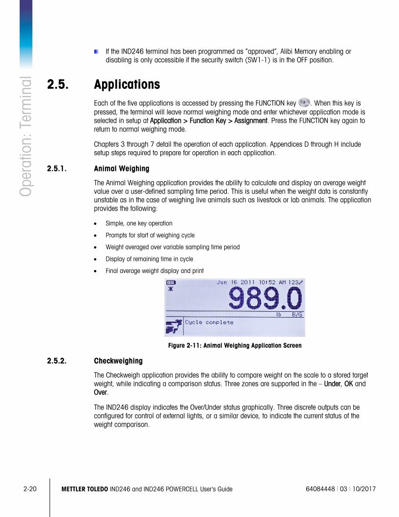
2-20 METTLER TOLEDO IND246 and IND246 POWERCELL User's Guide 64084448 | 03 | 10/2017
Ope
ratio
n: T
erm
inal
If the IND246 terminal has been programmed as “approved”, Alibi Memory enabling or
disabling is only accessible if the security switch (SW1-1) is in the OFF position.
2.5. Applications Each of the five applications is accessed by pressing the FUNCTION key . When this key is pressed, the terminal will leave normal weighing mode and enter whichever application mode is selected in setup at Application > Function Key > Assignment. Press the FUNCTION key again to return to normal weighing mode.
Chapters 3 through 7 detail the operation of each application. Appendices D through H include setup steps required to prepare for operation in each application.
2.5.1. Animal Weighing
The Animal Weighing application provides the ability to calculate and display an average weight value over a user-defined sampling time period. This is useful when the weight data is constantly unstable as in the case of weighing live animals such as livestock or lab animals. The application provides the following:
• Simple, one key operation
• Prompts for start of weighing cycle
• Weight averaged over variable sampling time period
• Display of remaining time in cycle
• Final average weight display and print
Figure 2-11: Animal Weighing Application Screen
2.5.2. Checkweighing
The Checkweigh application provides the ability to compare weight on the scale to a stored target weight, while indicating a comparison status. Three zones are supported in the – Under, OK and Over.
The IND246 display indicates the Over/Under status graphically. Three discrete outputs can be configured for control of external lights, or a similar device, to indicate the current status of the weight comparison.
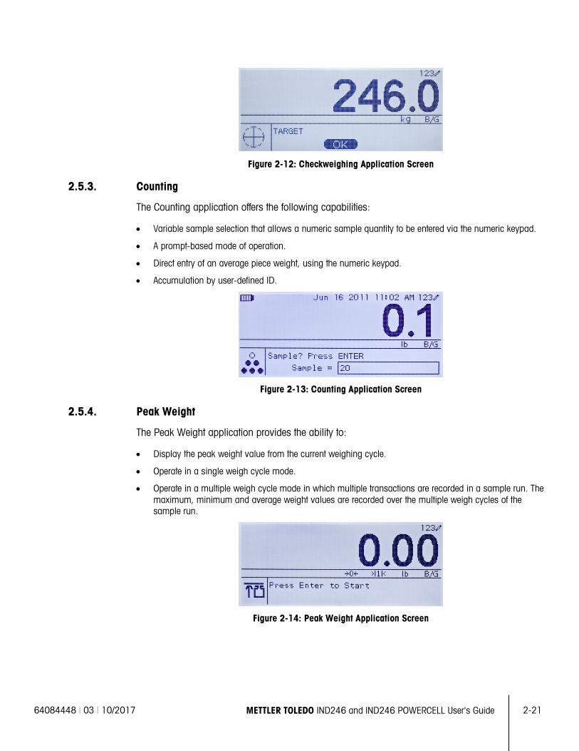
64084448 | 03 | 10/2017 METTLER TOLEDO IND246 and IND246 POWERCELL User's Guide 2-21
Figure 2-12: Checkweighing Application Screen
2.5.3. Counting
The Counting application offers the following capabilities:
• Variable sample selection that allows a numeric sample quantity to be entered via the numeric keypad.
• A prompt-based mode of operation.
• Direct entry of an average piece weight, using the numeric keypad.
• Accumulation by user-defined ID.
Figure 2-13: Counting Application Screen
2.5.4. Peak Weight
The Peak Weight application provides the ability to:
• Display the peak weight value from the current weighing cycle.
• Operate in a single weigh cycle mode.
• Operate in a multiple weigh cycle mode in which multiple transactions are recorded in a sample run. The maximum, minimum and average weight values are recorded over the multiple weigh cycles of the sample run.
Figure 2-14: Peak Weight Application Screen
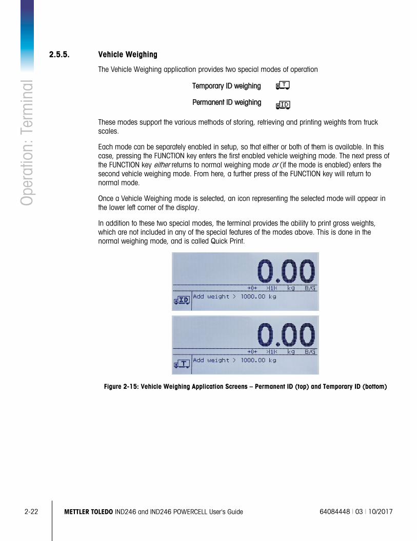
2-22 METTLER TOLEDO IND246 and IND246 POWERCELL User's Guide 64084448 | 03 | 10/2017
Ope
ratio
n: T
erm
inal
2.5.5. Vehicle Weighing
The Vehicle Weighing application provides two special modes of operation
Temporary ID weighing
Permanent ID weighing
These modes support the various methods of storing, retrieving and printing weights from truck scales.
Each mode can be separately enabled in setup, so that either or both of them is available. In this case, pressing the FUNCTION key enters the first enabled vehicle weighing mode. The next press of the FUNCTION key either returns to normal weighing mode or (if the mode is enabled) enters the second vehicle weighing mode. From here, a further press of the FUNCTION key will return to normal mode.
Once a Vehicle Weighing mode is selected, an icon representing the selected mode will appear in the lower left corner of the display.
In addition to these two special modes, the terminal provides the ability to print gross weights, which are not included in any of the special features of the modes above. This is done in the normal weighing mode, and is called Quick Print.
Figure 2-15: Vehicle Weighing Application Screens – Permanent ID (top) and Temporary ID (bottom)
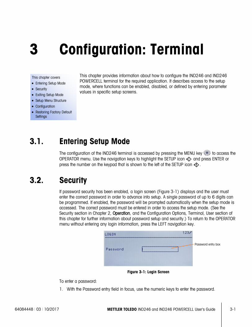
64084448 | 03 | 10/2017 METTLER TOLEDO IND246 and IND246 POWERCELL User's Guide
3-1
This chapter covers
• Entering Setup Mode
• Security
• Exiting Setup Mode
• Setup Menu Structure
• Configuration
• Restoring Factory Default Settings
3 Configuration: Terminal This chapter provides information about how to configure the IND246 and IND246 POWERCELL terminal for the required application. It describes access to the setup mode, where functions can be enabled, disabled, or defined by entering parameter values in specific setup screens.
3.1. Entering Setup Mode The configuration of the IND246 terminal is accessed by pressing the MENU key to access the OPERATOR menu. Use the navigation keys to highlight the SETUP icon and press ENTER or press the number on the keypad that is shown to the left of the SETUP icon .
3.2. Security If password security has been enabled, a login screen (Figure 3-1) displays and the user must enter the correct password in order to advance into setup. A single password of up to 6 digits can be programmed. If enabled, the password will be prompted automatically when the setup mode is accessed. The correct password must be entered in order to access the setup mode. (See the Security section in Chapter 2, Operation, and the Configuration Options, Terminal, User section of this chapter for further information about password setup and security.) To return to the OPERATOR menu without entering any login information, press the LEFT navigation key.
Figure 3-1: Login Screen
To enter a password:
1. With the Password entry field in focus, use the numeric keys to enter the password.
Password entry box
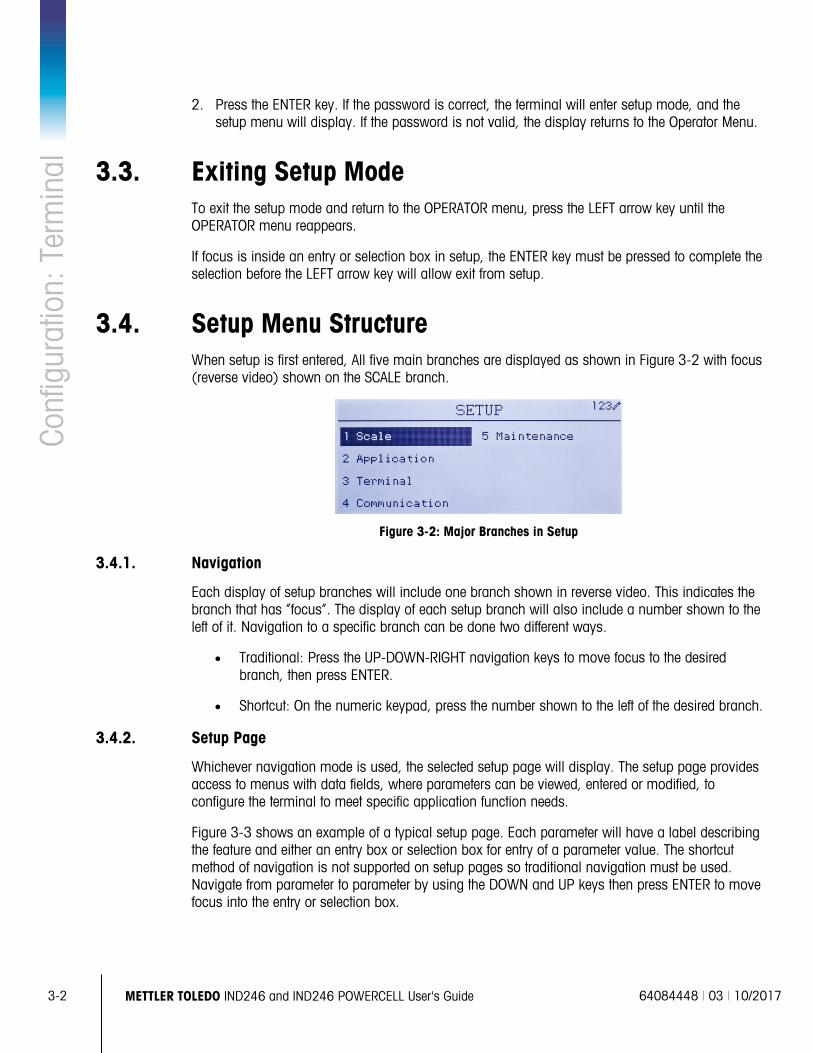
3-2
METTLER TOLEDO IND246 and IND246 POWERCELL User's Guide 64084448 | 03 | 10/2017
Conf
igur
atio
n: T
erm
inal
2. Press the ENTER key. If the password is correct, the terminal will enter setup mode, and the
setup menu will display. If the password is not valid, the display returns to the Operator Menu.
3.3. Exiting Setup Mode To exit the setup mode and return to the OPERATOR menu, press the LEFT arrow key until the OPERATOR menu reappears.
If focus is inside an entry or selection box in setup, the ENTER key must be pressed to complete the selection before the LEFT arrow key will allow exit from setup.
3.4. Setup Menu Structure When setup is first entered, All five main branches are displayed as shown in Figure 3-2 with focus (reverse video) shown on the SCALE branch.
Figure 3-2: Major Branches in Setup
3.4.1. Navigation
Each display of setup branches will include one branch shown in reverse video. This indicates the branch that has “focus”. The display of each setup branch will also include a number shown to the left of it. Navigation to a specific branch can be done two different ways.
• Traditional: Press the UP-DOWN-RIGHT navigation keys to move focus to the desired branch, then press ENTER.
• Shortcut: On the numeric keypad, press the number shown to the left of the desired branch.
3.4.2. Setup Page
Whichever navigation mode is used, the selected setup page will display. The setup page provides access to menus with data fields, where parameters can be viewed, entered or modified, to configure the terminal to meet specific application function needs.
Figure 3-3 shows an example of a typical setup page. Each parameter will have a label describing the feature and either an entry box or selection box for entry of a parameter value. The shortcut method of navigation is not supported on setup pages so traditional navigation must be used. Navigate from parameter to parameter by using the DOWN and UP keys then press ENTER to move focus into the entry or selection box.
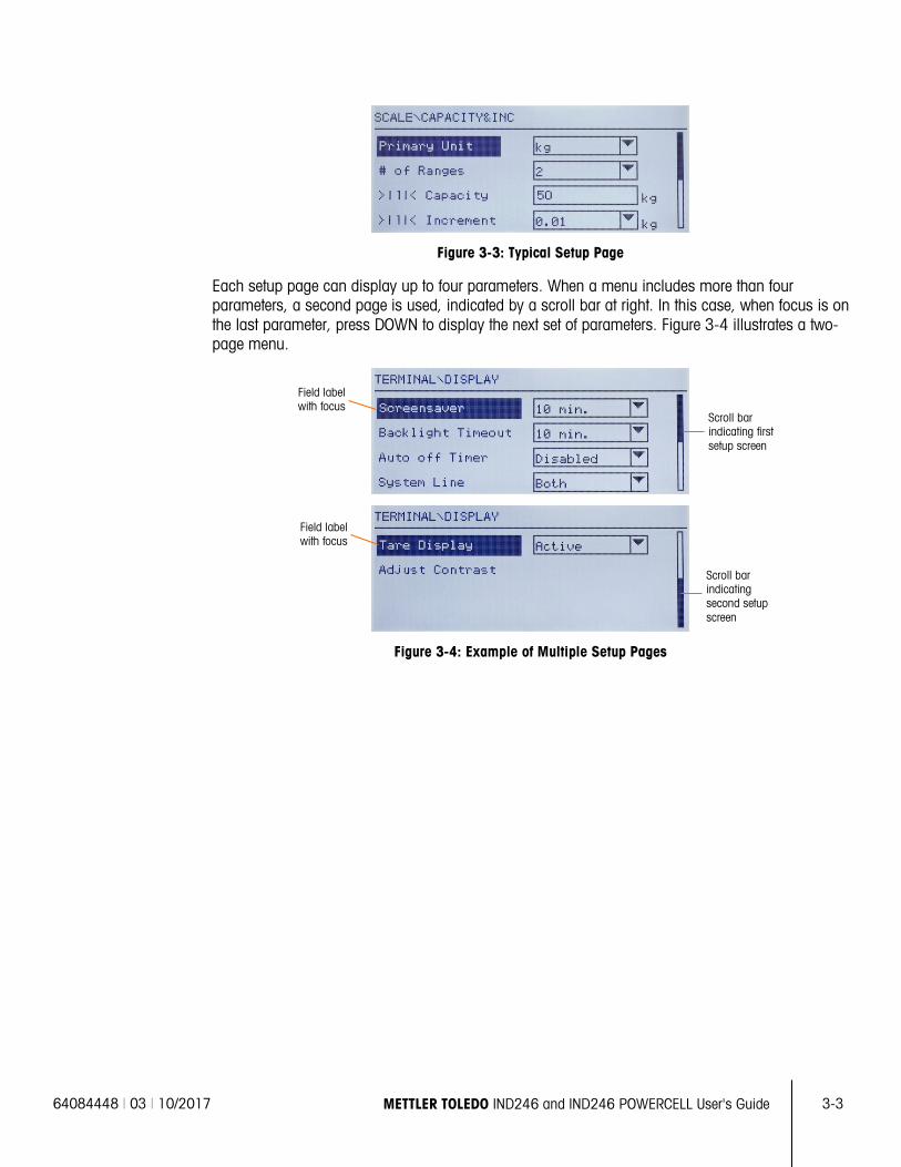
64084448 | 03 | 10/2017 METTLER TOLEDO IND246 and IND246 POWERCELL User's Guide
3-3
Figure 3-3: Typical Setup Page
Each setup page can display up to four parameters. When a menu includes more than four parameters, a second page is used, indicated by a scroll bar at right. In this case, when focus is on the last parameter, press DOWN to display the next set of parameters. Figure 3-4 illustrates a two-page menu.
Figure 3-4: Example of Multiple Setup Pages
Scroll bar indicating second setup screen
Scroll bar indicating first setup screen
Field label with focus
Field label with focus
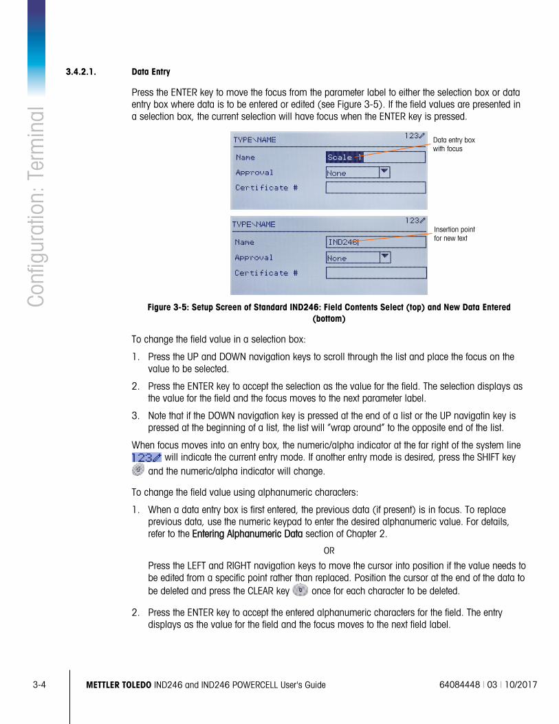
3-4
METTLER TOLEDO IND246 and IND246 POWERCELL User's Guide 64084448 | 03 | 10/2017
Conf
igur
atio
n: T
erm
inal
3.4.2.1. Data Entry
Press the ENTER key to move the focus from the parameter label to either the selection box or data entry box where data is to be entered or edited (see Figure 3-5). If the field values are presented in a selection box, the current selection will have focus when the ENTER key is pressed.
Figure 3-5: Setup Screen of Standard IND246: Field Contents Select (top) and New Data Entered
(bottom)
To change the field value in a selection box:
1. Press the UP and DOWN navigation keys to scroll through the list and place the focus on the value to be selected.
2. Press the ENTER key to accept the selection as the value for the field. The selection displays as the value for the field and the focus moves to the next parameter label.
3. Note that if the DOWN navigation key is pressed at the end of a list or the UP navigatin key is pressed at the beginning of a list, the list will “wrap around” to the opposite end of the list.
When focus moves into an entry box, the numeric/alpha indicator at the far right of the system line will indicate the current entry mode. If another entry mode is desired, press the SHIFT key
and the numeric/alpha indicator will change.
To change the field value using alphanumeric characters:
1. When a data entry box is first entered, the previous data (if present) is in focus. To replace previous data, use the numeric keypad to enter the desired alphanumeric value. For details, refer to the Entering Alphanumeric Data section of Chapter 2.
OR
Press the LEFT and RIGHT navigation keys to move the cursor into position if the value needs to be edited from a specific point rather than replaced. Position the cursor at the end of the data to be deleted and press the CLEAR key once for each character to be deleted.
2. Press the ENTER key to accept the entered alphanumeric characters for the field. The entry displays as the value for the field and the focus moves to the next field label.
Data entry box with focus
Insertion point for new text
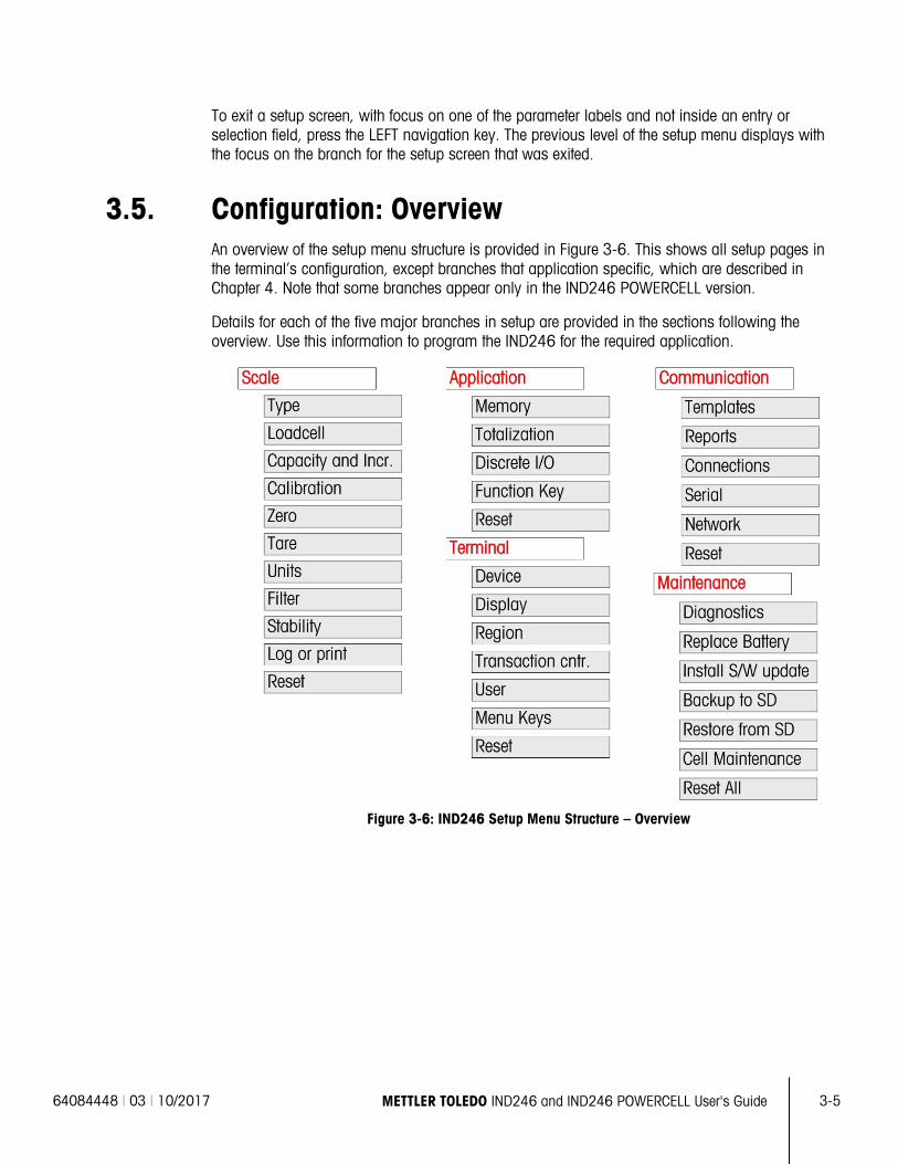
64084448 | 03 | 10/2017 METTLER TOLEDO IND246 and IND246 POWERCELL User's Guide
3-5
To exit a setup screen, with focus on one of the parameter labels and not inside an entry or selection field, press the LEFT navigation key. The previous level of the setup menu displays with the focus on the branch for the setup screen that was exited.
3.5. Configuration: Overview An overview of the setup menu structure is provided in Figure 3-6. This shows all setup pages in the terminal’s configuration, except branches that application specific, which are described in Chapter 4. Note that some branches appear only in the IND246 POWERCELL version.
Details for each of the five major branches in setup are provided in the sections following the overview. Use this information to program the IND246 for the required application.
Figure 3-6: IND246 Setup Menu Structure – Overview
3-6
METTLER TOLEDO IND246 and IND246 POWERCELL User's Guide 64084448 | 03 | 10/2017
Conf
igur
atio
n: T
erm
inal
3.6. Configuration: Scale Note that some branches and parameters are present only in the IND246 POWERCELL version.
If the metrology switch is in the approved position (SW1-1 = ON), access to certain parameters in the Scale branch is restricted. These parameters can be viewed but cannot be changed when the scale is “sealed”.
3.6.1. Type
The Type screens permit the entry of basic information about the attached scale, including:
• Scale name
• Type of scale
• Number of attached load cells
• Approval region
• Weights and Measures approval certificate number
The LEFT navigation key returns the display to the setup menu.
3.6.1.1. Name
The Name field enables entry of the scale identification. Enter the scale name (an alphanumeric string of up to 20 characters) in the Name entry box. This name will then be available as a selectable field in a print template.
3.6.1.2. Scale Type
Select the type of POWERCELL load cells connected to the terminal. The choices are:
• POWERCELL PDX
• POWERCELL GDD
• POWERCELL SLB615D
• POWERCELL SLC611D
3.6.1.3. # of Load Cells
The number of load cells connected to the terminal.
3.6.1.4. Approval
Approval refers to the metrological (weights and measures) approval configuration for the specific scale. The selection list can be set to:
• None – no approval is required
• Argentina
• Australia
64084448 | 03 | 10/2017 METTLER TOLEDO IND246 and IND246 POWERCELL User's Guide
3-7
• Canada
• OIML
• Sri Lanka (POWERCELL ONLY) • USA
If an approval for USA, OIML, Canada or Australia is configured and the metrology security switch, SW1-1, is set to ON, access to metrological parameters in the Scale setup branch will be limited to view only.
If the approval is configured for Argentina, and the metrology security switch SW1-1 is set to ON, access to the entire setup menu is prohibited. If an attempt is made to access the setup menu, a message will display: Access denied. Scale is approved.
When an approval region is selected, the terminal will require that SW1-1 be turned ON before setup can be exited. If an approval is selected and SW1-1 is not ON, an error message of [Err 0001] will appear when trying to exit setup.
3.6.1.5. Certificate #
The Certificate field enables entry of the W&M certificate number for the region. This data is shown on the Information Recall screen along with other approval information. Enter the certificate number (an alphanumeric string of up to 16 characters) in the entry box.
3.6.2. Load Cell
The Load Cell screen provides access to parameters specific to the POWERCELL PDX, GDD and SLC611D load cells.
The parameters are:
• Single Cell Address
• Manual Address
• Shift Adjust
• Shift Adjust Single
The load cell screens are used to address the POWERCELL PDX, GDD or SLC611D load cells and perform a shift adjustment. There are two different methods provided to address the PDX or GDD load cells. Refer to Table 3-1 as a guide as to which one to use.
Table 3-1: Addressing Method
Cell Address Method Description
Single Cell Addressing This procedure would typically be used after the replacement of a cell, off-site testing or pre-installation when there is no cell-to-cell cable available. It typically is used to discover a single connected cell’s serial number and node address. During an actual on-site installation when many load cells are already connected in the network, or when installing a new scale, the Manual Address procedure should be used.
Manual Address Typically, this procedure is used when installing a new scale with load cells that have the factory default node address. The serial number and location of each cell

3-8
METTLER TOLEDO IND246 and IND246 POWERCELL User's Guide 64084448 | 03 | 10/2017
Conf
igur
atio
n: T
erm
inal
Cell Address Method Description
must be known.
3.6.2.1. Single Cell Address, Manual
When auto-addressing a single new SLB615D, refer to section 3.10.2.5.
Use the Single Cell Address step to reassign the node address of a single connected load cell identified by its serial number or to its factory default node address of 125. This procedure would typically be used after the replacement of a cell.
Follow this procedure to perform a single cell address:
1. The initial screen prompts for the connection of the load cell.
2. Make sure the PDX or GDD cell that needs to be addressed is connected and press ENTER to begin the process, or the LEFT arrow to exit. The display indicates that load cell discovery process has begun, and then displays the cell’s address.
3. When this discovery process is completed, the terminal will display the serial number and node address of the first cell it discovers. The node address of the cell can now be reassigned
4. To quit the addressing process or return to the Single Cell Address Start screen, press the LEFT arrow. Otherwise, enter the required address in the Node entry box and press ENTER to start the addressing process.
5. Press the LEFT arrow to return to the setup menu tree.
3.6.2.2. Single Cell Address, Automatic
When installing a single new load cell which has a factory default cell address, the cell can be replaced without manually addressing it to the missing node. After the cell has been replaced, the IND246 displays a prompt indicating that the new cell has been found, and requesting operator confirmation. Once the replacement is confirmed by selecting Yes, the system automatically assigns the missing node address to the new cell. If the user declines the prompt by selecting No, a prompt appears offering the option to assign a different node address.
This method cannot be used if more than one cell is replaced, or if the replaced cell does not have the factory default load cell address.
If the terminal is in Weights and Measures sealed mode, the automatic addressing procedure cannot be used without applications without breaking the seal.
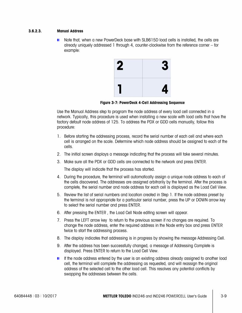
64084448 | 03 | 10/2017 METTLER TOLEDO IND246 and IND246 POWERCELL User's Guide
3-9
3.6.2.3. Manual Address
Note that, when a new PowerDeck base with SLB615D load cells is installed, the cells are already uniquely addressed 1 through 4, counter-clockwise from the reference corner – for example:
Figure 3-7: PowerDeck 4-Cell Addressing Sequence
Use the Manual Address step to program the node address of every load cell connected in a network. Typically, this procedure is used when installing a new scale with load cells that have the factory default node address of 125. To address the PDX or GDD cells manually, follow this procedure:
1. Before starting the addressing process, record the serial number of each cell and where each cell is arranged on the scale. Determine which node address should be assigned to each of the cells.
2. The initial screen displays a message indicating that the process will take several minutes.
3. Make sure all the PDX or GDD cells are connected to the network and press ENTER.
The display will indicate that the process has started.
4. During the procedure, the terminal will automatically assign a unique node address to each of the cells discovered. The addresses are assigned arbitrarily by the terminal. After the process is complete, the serial number and node address for each cell is displayed as the Load Cell View.
5. Review the list of serial numbers and location created in Step 1. If the node address preset by the terminal is not appropriate for a particular serial number, press the UP or DOWN arrow key to select the serial number and press ENTER.
6. After pressing the ENTER , the Load Cell Node editing screen will appear.
7. Press the LEFT arrow key to return to the previous screen if no changes are required. To change the node address, enter the required address in the Node entry box and press ENTER twice to start the addressing process.
8. The display indicates that addressing is in progress by showing the message Addressing Cell.
9. After the address has been successfully changed, a message of Addressing Complete is displayed. Press ENTER to return to the Load Cell View.
If the node address entered by the user is an existing address already assigned to another load cell, the terminal will complete the addressing as requested, and will reassign the original address of the selected cell to the other load cell. This resolves any potential conflicts by swapping the addresses between the cells.
3-10
METTLER TOLEDO IND246 and IND246 POWERCELL User's Guide 64084448 | 03 | 10/2017
Conf
igur
atio
n: T
erm
inal
10. Repeat steps 5 – 9 to address another cell, or press the LEFT to return to the Scale/Load Cell
menu.
3.6.2.4. Shift Adjust
Depending on the location of the test weight on the scale, small mismatches in mechanical and electronic gain of the load sensing paths can cause the same test weight to produce slightly different readings. The IND246 POWERCELL provides two types of adjustment – adjustment by individual cells or adjustment by pairs of cells.
The Shift Adjust by Cell or Pair parameter is preset to Cell and cannot be changed when fewer than four POWERCELL load cells are used.
3.6.2.4.1. Adjust by Cell
Adjustment by Cell adds a factor to each load cell’s output to compensate for the slight differences between them. The scale will then output the same weight value regardless of the physical location of the weight on the scale.
3.6.2.4.2. Adjust by Pair
Adjustment by Pair ensures a constant reading from the scale regardless of where the load is placed on the long axis between pairs of cells – for instance, in vehicle weighing applications. Before beginning the shift adjustment procedure, select whether the adjustment will be done by cell or by pair. The procedure for shift adjusting by pair of cells is listed below. The procedure for shift adjusting by individual cell follows the same sequence, but cells are read and adjusted one at a time.
For either case, enter setup and access Scale > LoadCell > Shift Adjust.
The procedure for shift adjusting by pair of cells is:
1. In the Adjust By selection list, select Pair and press the ENTER key.
2. The display shows the space on the first two lines for the number of counts for each cell. A prompt will appear: Empty scale, press ENTER. Empty the scale then press the ENTER key.
3. The display will indicate that the initial reading is taking place by showing the message Getting Counts.
4. After the initial zero reading is complete, follow the on-screen prompt of Press ENTER after putting a weight on load cell 1&2 (where 1&2 identifies the first cell pair being adjusted). The test load should be centered between the specified cells.
5. An on-screen message will indicate that the terminal is Getting Counts. The Cell Counts lines will change to reflect the new readings from the load cells, and the prompt will show Press ENTER after putting a weight on load cell 3&4" (where 3&4 identifies the next cell pair).
6. Move the test load from the previous pair of cells to the next pair keeping the load centered between the cells. Press ENTER to continue.
7. The display will show Getting Counts.
8. Repeat steps 5 through 7 until all cell pairs have been adjusted. An on-screen message of Adjust OK, press ENTER to return will then be displayed.
9. Press ENTER to return to the Scale/Load cell menu.
64084448 | 03 | 10/2017 METTLER TOLEDO IND246 and IND246 POWERCELL User's Guide
3-11
3.6.2.4.3. Shift Adjust Single
This procedure allows you to quickly adjust the shift values for a single pair or single cell after a cell has been replaced on the scale. A complete shift adjust (previous setup branch) is more accurate and should be used if more than one POWERCELL cell has been replaced on the scale.
The Shift Adjust Cell or Pair branch is accessible based on if Cell or Pair was selected in setup at Scale > Load Cell > Shift Adjust
Based on the selection made in the Shift Adjust > Shift By Cell or Pair parameter (step 1 above), the terminal allows adjustment by either Cell or Pair. The following example describes the procedure when adjusting by cell. The adjustment by pair follows the same procedure except the terminal will prompt for weight to be placed between a pair of cells instead of a single cell.
To do a single cell/pair shift adjust, enter setup and access Scale > Load Cell > Shift Adjust Single.
To adjust a specific cell (in this example, cell 3):
1. Select the cell to adjust, then press ENTER to start. An on-screen prompt will appear: Empty scale, press ENTER.
2. The display will display Getting Counts, to indicate that the initial reading is taking place.
3. After the initial zero reading is complete, follow the on-screen prompt: Press ENTER after putting a weight on load cell # 3 (or the addresse of the current cell being adjusted).
4. An on-screen message will indicate that the terminal is Getting Counts. The cell count lines will change to reflect the new reading from the load cell, and then the prompt will appear: Press ENTER after putting a weight on Load Cell 4.
5. Move the test load from the current cell to the next prompted cell, then press ENTER to continue.
6. The display will indicate that the cell is being read: Getting Counts.
7. When the process is complete, the display will show Adjust OK. Press ENTER to return. Press ENTER to return to the setup menu tree.
3.6.2.4.4. Shift Adjust Values
To view the Shift Adjust values in setup, access Maintenance > Diagnostics > Scale > Shift Adjust.
3.6.3. Capacity and Increment
Use the Capacity and Increment setup screen to select primary units, set the number of weighing ranges, and the scale capacity and increment size.
3.6.3.1. Primary Units
Set the primary units from the selection box choices, which include:
Grams (g) Pounds (lb) Tons (ton)
Kilograms (kg) Tonnes (t)
3-12
METTLER TOLEDO IND246 and IND246 POWERCELL User's Guide 64084448 | 03 | 10/2017
Conf
igur
atio
n: T
erm
inal
3.6.3.2. #Ranges/Increments
The IND246 can be configured to use one or two ranges, or (in the case of IND246 POWERCELL) one or two intervals. Each range or interval can be assigned its own increment. With multiple ranges configured, the increment changes when the weight exceeds the capacity of Range 1, and remains the same until the weight returns to within the zero tolerance. With multiple intervals configured, the increment changes when the weight exceeds the capacity of Interval 1, and returns to the interval 1 increment when the weight falls below the value defined as the start of Interval 2.
Options are:
• 1
• 2 Intervals
• 2 Ranges
3.6.3.2.1. 1 Range
When 1 is selected the terminal functions with a single range, and the additional parameters available are:
• >|1|< Capacity
• >|1|< Increment
3.6.3.2.2. 2 Intervals (POWERCELL only)
In this case, the terminal functions with two ranges, each with its own increment. The increment size will change when the weight reaches the second range. In addition to the Range 1 Capacity and Increment parameters, the following two settings are available:
• >|2|< Capacity
• >|2|< Increment
3.6.3.2.3. 2 Ranges
In addition to the Interval 1 Capacity and Increment parameters, the following two settings are available:
• >|2|< Capacity
• >|2|< Increment
3.6.3.2.4. >|1|< Capacity
Specify the weight capacity for range 1. If only one range is enabled, this will be the scale capacity and the display will show an overcapacity graphic if the weight exceeds this value by more than five increments. If two ranges are enabled, this will be the weight at which the increment size changes from the range 1 increment size to the range 2 increment size.
3.6.3.2.5. >|1|< Increment
Specify the increment size for weighing range 1. If only one range is enabled, this will be the increment size for the entire weighing range of the scale. If two ranges are enabled, this will be the increment used in the lower range.
64084448 | 03 | 10/2017 METTLER TOLEDO IND246 and IND246 POWERCELL User's Guide
3-13
3.6.3.2.6. >|2|< Capacity
Specify the weight capacity for range 2. If only one range is enabled, this parameter will not be shown. If two ranges are selected, this will be the scale capacity and the display will show an overcapacity graphic if the weight exceeds this value by more than five increments.
3.6.3.2.7. >|2|< Increment
Specify the increment size for weighing range 2. If only one range is enabled, this parameter will not be shown. If two ranges are selected, this will be the increment size for the second weighing range of the scale.
To use multiple range mode, the ratio of range 2 increment to range 1 increment must be less than 50.
3.6.4. Calibration
The Calibration screen enables entry of a GEO code adjustment value, linearity adjustment, and provides access to zero and span adjustments.
3.6.4.1. GEO Code
Enter the GEO code for the appropriate adjustment value for the current geographical location. GEO codes are numbered 0–31. (Refer to Appendix D.)
When the load cell type is SLB615D, and a new PowerDeck is connected to the terminal (or after a Master Reset is performed, or the terminal’s main PCB is replaced), and the terminal is not in Weights and Measures sealed mode, the terminal will automatically prompt for the local GEO code. It will then read the calibration data from the load cells, and the system will be ready for use.
3.6.4.2. Linearity Adjustment
Select if a linearity adjustment will be used during calibration. Selections are as follows:
Disabled – Use only zero and one span point
Enabled – Use zero, mid span point, and high span point
3.6.4.3. Set Zero
The Set Zero function in the Calibration setup triggers an independent operation to reset the zero condition of the scale. A status message displays when this function is accessed that directs the user to empty the scale and press the ENTER key. The status of the capture zero operation displays. When the operation is complete, a final status message displays that verifies the completion of the capture zero operation.
If motion is present during the zero capture process, the terminal will average the weight readings then display a message indicating unstable weight values were used. This message must be acknowledged to save the values.
3.6.4.4. Set Span
The Set Span function in the Calibration setup initiates a sequence to capture span that can be performed independently of capturing zero.
3-14
METTLER TOLEDO IND246 and IND246 POWERCELL User's Guide 64084448 | 03 | 10/2017
Conf
igur
atio
n: T
erm
inal
To capture span:
1. With focus on the Set Span label, press ENTER. The Capture Span setup screen displays.
2. Enter the weight for test load 1 (and test load 2 if linearity has been enabled). Press the ENTER key.
3. Place test load weight 1 on the scale.
4. With focus on the Place xxxx, press ENTER text, press the ENTER key. The status of the weight capture operation displays. When the operation is complete, a status message displays that verifies the completion of the weight capture.
Press the LEFT navigation key if the calibration process must be aborted and the display will return to the previous screen.
5. After the first calibration step has completed, the menu will either display a prompt for the next calibration weight to be added (if linearity adjustment parameter is enabled) or will show a successful or failed calibration sequence.
If motion is present during the span capture process, the terminal will average the weight readings then display a message indicating unstable weight values were used. This message must be acknowledged to save the values.
6. Repeat steps 3 and 4 for test load 2 if enabled by linearity adjustment.
7. If the capture span operation was successful, a verification message that reads “Capture Span OK” displays If the capture span operation was not successful, an error message that reads “Calibration Failure” displays. If the calibration fails, repeat the capture span procedures. If the calibration continues to fail, contact a local METTLER TOLEDO representative for assistance.
8. Press the LEFT navigation key to return to the Calibration screen.
3.6.5. Zero
This section provides access to Auto Zero Maintenance (AZM) settings, under zero blanking, power-up zero, and pushbutton zero parameters.
3.6.5.1. Auto Zero
AZM is a means of tracking zero when the scale is empty. AZM compensates for conditions such as terminal or load cell drift or debris on a scale platform.
Use the Auto Zero setup screen to enable auto zero for gross weighing or gross and net weighing, or to turn auto zero off.
3.6.5.2. Auto Zero Range
Set the auto zero range for the number of divisions (d) around the current zero setting in which auto zero will operate. Selections include 0.5, 1, 3 and 10 d.
3.6.5.3. Under Zero Blanking
When Under Zero Blanking is set to Disabled, the terminal displays a negative weight as far below zero as possible when the weight goes under gross zero. Other options are:
64084448 | 03 | 10/2017 METTLER TOLEDO IND246 and IND246 POWERCELL User's Guide
3-15
20d The terminal displays a negative weight until 20 divisions below zero, and then blanks the display.
20d with Zero The terminal displays a negative weight until 20 divisions below zero, and then blanks the display. The display remains blanked until the scale is manually zeroed. This feature is required for approval in Thailand.
3.6.5.4. Power Up Zero
A Power Up setting of Disabled enables the terminal to save and reuse the last zero reference weight after a power cycle so it returns to the same gross or net weight value. If a power up range of +/-2% or +/-10% is selected, the terminal tries to capture zero upon power up.
For example, if the setting for Power Up Zero is set at 2%, Power Up Zero will only occur when the weight reading on the scale is within +/- 2% of the original calibrated zero condition.
If Power Up Zero capture is enabled and the weight on the scale is outside of the zero capture range, the display will indicate [ E E E ] until the weight is removed and zero is captured.
3.6.5.5. Pushbutton Zero
If Pushbutton Zero is Disabled, the front panel ZERO pushbutton will not operate to capture a new zero reference point. If a range of +/-2% or +/- 20% is selected, pushbutton zero will operate within the selected range to rezero the scale.
If Pushbutton Zero is Disabled, execution of a remote Zero is still possible via SICS or CPTZ commands from a PC and a discrete input command.
For example, if the setting for Pushbutton Zero is set at +/-2%, the Pushbutton Zero can only be used when the weight reading on the scale is within +/- 2% of the original calibrated zero condition.
3.6.6. Tare
Tare is used to subtract the weight of an empty container from the gross weight on the scale to determine the net weight of the contents. Tare is inhibited if the scale is in motion.
Three setup screens are available to configure tare:
Tare Types Auto Tare Auto Clear
3.6.6.1. Tare Types
Use the Tare Types setup screen to enable or disable pushbutton tare, keyboard tare, and net sign correction.
3.6.6.1.1. Pushbutton Tare
When pushbutton tare is Enabled, the TARE scale function key can be pressed when an empty container is on the scale to determine tare. The terminal displays a zero weight and net mode. When the container is loaded and placed back on the scale, the terminal displays the net weight of the contents.
If Pushbutton Tare is Disabled, execution of a remote Tare is still possible via SICS or CPTZ commands or from discrete input command.
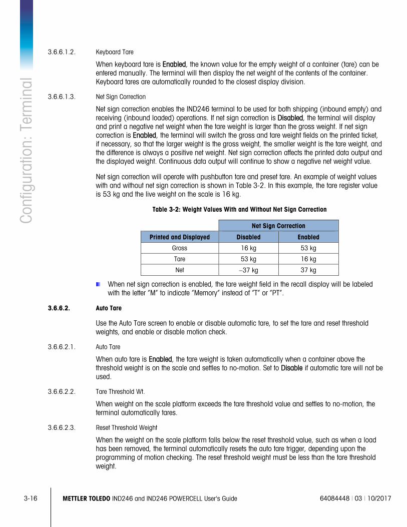
3-16
METTLER TOLEDO IND246 and IND246 POWERCELL User's Guide 64084448 | 03 | 10/2017
Conf
igur
atio
n: T
erm
inal
3.6.6.1.2. Keyboard Tare
When keyboard tare is Enabled, the known value for the empty weight of a container (tare) can be entered manually. The terminal will then display the net weight of the contents of the container. Keyboard tares are automatically rounded to the closest display division.
3.6.6.1.3. Net Sign Correction
Net sign correction enables the IND246 terminal to be used for both shipping (inbound empty) and receiving (inbound loaded) operations. If net sign correction is Disabled, the terminal will display and print a negative net weight when the tare weight is larger than the gross weight. If net sign correction is Enabled, the terminal will switch the gross and tare weight fields on the printed ticket, if necessary, so that the larger weight is the gross weight, the smaller weight is the tare weight, and the difference is always a positive net weight. Net sign correction affects the printed data output and the displayed weight. Continuous data output will continue to show a negative net weight value.
Net sign correction will operate with pushbutton tare and preset tare. An example of weight values with and without net sign correction is shown in Table 3-2. In this example, the tare register value is 53 kg and the live weight on the scale is 16 kg.
Table 3-2: Weight Values With and Without Net Sign Correction
Net Sign Correction
Printed and Displayed Disabled Enabled
Gross 16 kg 53 kg
Tare 53 kg 16 kg
Net −37 kg 37 kg
When net sign correction is enabled, the tare weight field in the recall display will be labeled with the letter “M” to indicate “Memory” instead of “T” or “PT”.
3.6.6.2. Auto Tare
Use the Auto Tare screen to enable or disable automatic tare, to set the tare and reset threshold weights, and enable or disable motion check.
3.6.6.2.1. Auto Tare
When auto tare is Enabled, the tare weight is taken automatically when a container above the threshold weight is on the scale and settles to no-motion. Set to Disable if automatic tare will not be used.
3.6.6.2.2. Tare Threshold Wt.
When weight on the scale platform exceeds the tare threshold value and settles to no-motion, the terminal automatically tares.
3.6.6.2.3. Reset Threshold Weight
When the weight on the scale platform falls below the reset threshold value, such as when a load has been removed, the terminal automatically resets the auto tare trigger, depending upon the programming of motion checking. The reset threshold weight must be less than the tare threshold weight.
64084448 | 03 | 10/2017 METTLER TOLEDO IND246 and IND246 POWERCELL User's Guide
3-17
3.6.6.2.4. Motion Check
Enable the motion check setting to prevent auto tare reset rigger from occurring when the scale is in motion. When enabled, the scale must detect a non-motion condition below the reset value to reset the auto tare trigger.
3.6.6.3. Auto Clear
Use the Auto Clear screen to Enable or Disable auto clear tare, clear after print, to set the clear threshold weight, and enable or disable motion checking for auto clearing of tare.
3.6.6.3.1. Auto Clear Tare
To clear tare automatically when the scale returns to below the threshold weight, enable the auto clear tare setting.
3.6.6.3.2. Clear Threshold Wt.
When the gross scale weight exceeds then falls below the clear threshold weight value, the terminal automatically clears tare and returns to gross mode.
3.6.6.3.3. Motion Check
Enable the motion check setting to prevent auto clear from occurring when the scale is in motion below the threshold weight.
3.6.6.3.4. Clear After Print
The Clear After Print field displays only when Auto Clear Tare is enabled. To clear tare automatically after printing, Enable the clear after print setting. Select Disable to not clear tare after a print.
3.6.7. Units
This setup screen enables the selection of a second unit.
3.6.7.1. Second Unit
Use the Second Unit selection box to select a second weighing unit or to select none. The weight will be converted from primary to the selected secondary unit when the Units Switch key is pressed.
Available weighing units include:
Grams (g) Pounds (lb)
Kilograms (kg) Tonnes (t)
Ounces (oz) Tons (ton)
3.6.8. Filter
The IND246 terminal has a low-pass, multi-pole vibration filter that can be set for several conditions. The heavier the filtering, the slower the display settling time will be.
3-18
METTLER TOLEDO IND246 and IND246 POWERCELL User's Guide 64084448 | 03 | 10/2017
Conf
igur
atio
n: T
erm
inal
3.6.8.1. Low Pass Filter
Low Pass filter selections include Very Light, Light, Medium (default) and Heavy. This parameter sets the amount of filtering that is applied to the weight. The heavier the filter applied, the more stable the weight will be, but the longer the settling time required for the scale.
3.6.8.2. Stability Filter
The stability filter works in conjunction with the standard low pass filter to provide a more stable final weight reading. The stability filter should only be used in transaction weighing applications, since the nonlinear action of the filter switching may cause inaccurate cutoffs in filling applications. The stability filter can be Enabled or Disabled on this setup screen.
3.6.9. Stability
The IND246 terminal includes a stability detector (weight in motion). The Stability setup screen enables setting a motion range, no-motion interval and timeout period.
3.6.9.1. Motion Range
Sets the motion range of the weight value (in divisions) that the weight is permitted to fluctuate and still have a no-motion condition. Select a value from Disabled, 1d or 3d. If the motion range is disabled, motion detection is disabled and the scale will never indicate motion.
3.6.9.2. No-motion Interval
The no motion interval defines the amount of time (seconds) that the scale weight must be within the motion range to have a no-motion condition. Select a value from 0.3, 0.5, 0.7 or 1.0 seconds. A shorter interval means that a no-motion condition is more likely, but may cause the terminal to indicate no-motion while there is still a small amount of motion on the scale.
3.6.9.3. Timeout
Defines the period (in seconds) after which the terminal stops attempting to perform a function that requires a no-motion condition (such as a zero, tare or print command) and aborts the function. This timeout is used regardless of the source of the command such as the keypad, discrete input or SICS. Select a values from Disabled, 3, 10 or 30 seconds, the default value being 3. A smaller value means that less time will be used to check for no-motion before aborting a command. When disabled is selected, the terminal will abort the command if motion is detected.
3.6.10. Log or Print
The Log or Print setup branch is where the thresholds to control how and when data is saved or output to a printer are defined. Normal demand mode printing occurs whenever a print request is made, providing there is no motion on the scale and zero has been captured.
The weight values entered are the gross weight values in primary units. Gross weight in primary units is used regardless of whether the IND246 is in Gross or Net mode and regardless of the units that are displayed.
64084448 | 03 | 10/2017 METTLER TOLEDO IND246 and IND246 POWERCELL User's Guide
3-19
3.6.10.1. Minimum Weight
The minimum weight setting is the threshold below which log or print functions will not initiate. A value of 0 permits printing when any weight value is shown (not blanked over capacity or under zero.
3.6.10.2. Interlock
Interlock prevents repeat logging and printing without a weight change. If Enabled, interlock requires that the weight reading be reset per the “Reset on” parameter setting (see below) and then settle to a weight greater than the minimum print value before responding to the next log or print request. If Disabled, multiple prints of the same weight are possible.
3.6.10.3. Automatic
Enable the automatic setting to automatically log data and print every time the weight on the scale settles to a positive value that is larger than the entered threshold weight value.
If Automatic is set to Disabled, the Threshold Weight field does not appear and a print or log of data must be triggered manually.
3.6.10.4. Reset on
The resetting of auto printing or logging can be based on weight threshold or weight deviation values. Select Return (the weight must return to below this value to reset) or Deviation (the weight must change more than this value to reset) from the selection box and enter the weight value in the “Reset on” field.
If both “Interlock” and “Automatic” settings are disabled, the “Reset on” field does not display.
If “Reset on” is set to Deviation, The “Threshold Weight” and “Motion Check” fields do not display.
3.6.10.5. Threshold Weight
The Threshold Weight is the value above which an Automatic logging or printing of data can/will occur. Threshold Weight does not appear if “Automatic” is set to Disabled or if “Reset on” is set to Deviation.
3.6.10.6. Motion Check
Enable the motion check setting to prevent interlock and automatic log and print functions from resetting when the scale is in motion below the “Reset On” return point. Motion Check does not appear if “Reset on” is set to Deviation.
3.6.11. Scale Reset
To initiate a reset of the Scale branch, press the ENTER key. If the reset was successful, a verification message that reads “Reset Successful” displays If the reset was not successful, an error message that reads “Reset Failure” displays. If the reset fails, try to initiate the reset again. If the reset continues to fail, contact a local METTLER TOLEDO representative for assistance.
Press the LEFT navigation key to exit without resetting.
3-20
METTLER TOLEDO IND246 and IND246 POWERCELL User's Guide 64084448 | 03 | 10/2017
Conf
igur
atio
n: T
erm
inal
Scale reset does NOT include the reset of metrologically significant parameters – scale type,
approval, weight units, capacity, increment, or calibration data. This data is reset only by performing a Master Reset.
3.7. Configuration: Application 3.7.1. Memory
Memory setup screens includes parameters for Alibi memory.
3.7.1.1. Alibi Memory
The Alibi Memory can be Enabled or Disabled in the selection box. Alibi memory is configured as a “ring” buffer that overwrites the oldest record when it reaches its memory limit. Each time a demand print is triggered, specific data fields are stored in Alibi memory. Alibi memory can hold approximately 60,000 transactions before it reaches its limit and begins overwriting old transactions. More detailed information about Alibi memory can be found in Appendix C, Alibi Memory Structure.
The use of Alibi Memory requires installation of an SD memory card. Attempts to generate a print transaction from the front panel without an SD card installed return a pop-up error message SD card is not installed., while a print command issued serially or via an input will result in an SD memory card not installed message in the system line. The transaction counter will not increment.
The Alibi Memory table stores basic transaction information that is not user-definable. This information always includes:
• Date and time stamp
• Transaction counter value
• Gross, tare, and net weights and weight unit If the IND246 terminal has been programmed as “approved”, Alibi Memory enabling or
disabling is only accessible if the security switch (SW1-1) is in the OFF position.
3.7.2. Totalization
Use the Totalization setup screen to select parameters for totalization operations, including which source to use as input for totalization, settings for grand totals and subtotals, and to enable or disable the conversion of second unit weights for totalization. When a demand print occurs, the selected weight field will be added to the totals register.
3.7.2.1. Mode
Select which source to use as input for totalization comparison – either Displayed Weight or Gross Weight. A selection of None disables totalization.
3.7.2.2. Clear GT on Print
The Grand Total can be configured to clear automatically after printing the Totals report. If Clear GT on Print is Enabled, the subtotal also clears automatically after printing the Totals report.
64084448 | 03 | 10/2017 METTLER TOLEDO IND246 and IND246 POWERCELL User's Guide
3-21
3.7.2.3. Subtotal
The Subtotal can be separately disabled while the GT continues to accumulate weights. Choose to either Enable or Disable the subtotal register.
3.7.2.4. Clear ST on Print
Clearing the subtotal on print and not clearing the grand total on print allows the subtotal register to totalize sub-sets of weighments and to be reset while the grand total continues to track the grand total of weight. Choose to Clear ST on Print or not by selecting Enabled or Disabled in the selection box.
3.7.2.5. Convert Weight
The total registers always store weights in primary units. If Convert Weight is Disabled, scale weights other than primary units are not accumulated. If Convert Weight is Enabled, then the weight is converted to primary units, then accumulated.
3.7.3. Discrete I/O
Discrete I/O setup menus allow the configuration of 2 inputs and 4 outputs. The Discrete I/O option must be installed to program this functionality.
3.7.3.1. Inputs
The Discrete Input menus display discrete input polarity and assignments for Input 1 and Input 2. The two Inputs are configured in the same way.
3.7.3.1.1. Polarity
The inputs can be programmed to accept either a + True or – True polarity level as “ON”. The default is + True.
3.7.3.1.2. Assignment
Options for input assignment are:
• None (default) • SICS – S • Tare
• Blank Display • SICS – SI • Unit Switching
• Clear Tare • SICS – SIR • Zero
3.7.3.2. Outputs
For each Discrete Output, menus permit an assignment to be selected from the following options:
• None (default) • Motion • Over Capacity
• Center of Zero • Net • Under Zero
3.7.4. Function Key
The Function Key setup allows selection of the application that will be active when the FUNCTION key is pressed. Only one application can be selected.
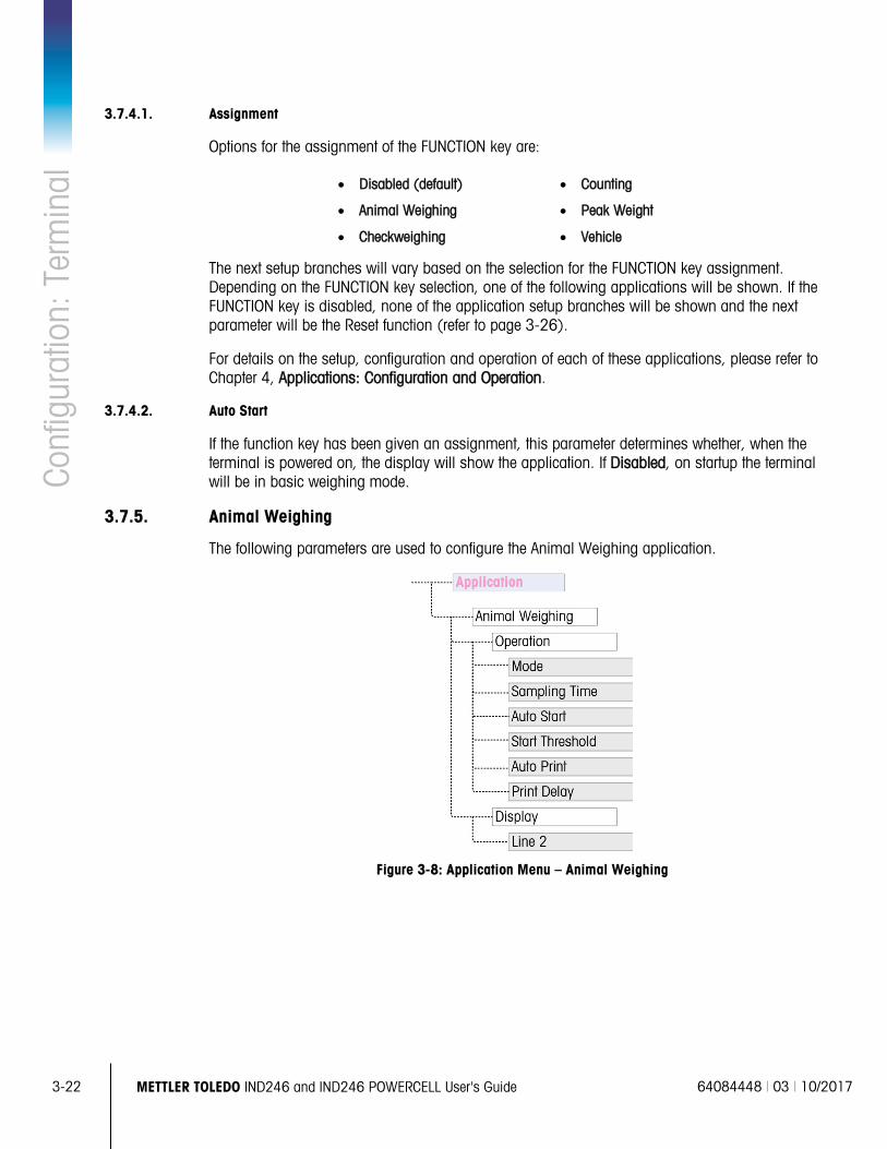
3-22
METTLER TOLEDO IND246 and IND246 POWERCELL User's Guide 64084448 | 03 | 10/2017
Conf
igur
atio
n: T
erm
inal
3.7.4.1. Assignment
Options for the assignment of the FUNCTION key are:
• Disabled (default) • Counting
• Animal Weighing • Peak Weight
• Checkweighing • Vehicle
The next setup branches will vary based on the selection for the FUNCTION key assignment. Depending on the FUNCTION key selection, one of the following applications will be shown. If the FUNCTION key is disabled, none of the application setup branches will be shown and the next parameter will be the Reset function (refer to page 3-26).
For details on the setup, configuration and operation of each of these applications, please refer to Chapter 4, Applications: Configuration and Operation.
3.7.4.2. Auto Start
If the function key has been given an assignment, this parameter determines whether, when the terminal is powered on, the display will show the application. If Disabled, on startup the terminal will be in basic weighing mode.
3.7.5. Animal Weighing
The following parameters are used to configure the Animal Weighing application.
Figure 3-8: Application Menu – Animal Weighing
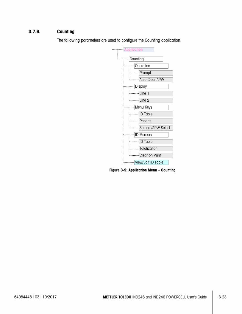
64084448 | 03 | 10/2017 METTLER TOLEDO IND246 and IND246 POWERCELL User's Guide
3-23
3.7.6. Counting
The following parameters are used to configure the Counting application.
Figure 3-9: Application Menu – Counting
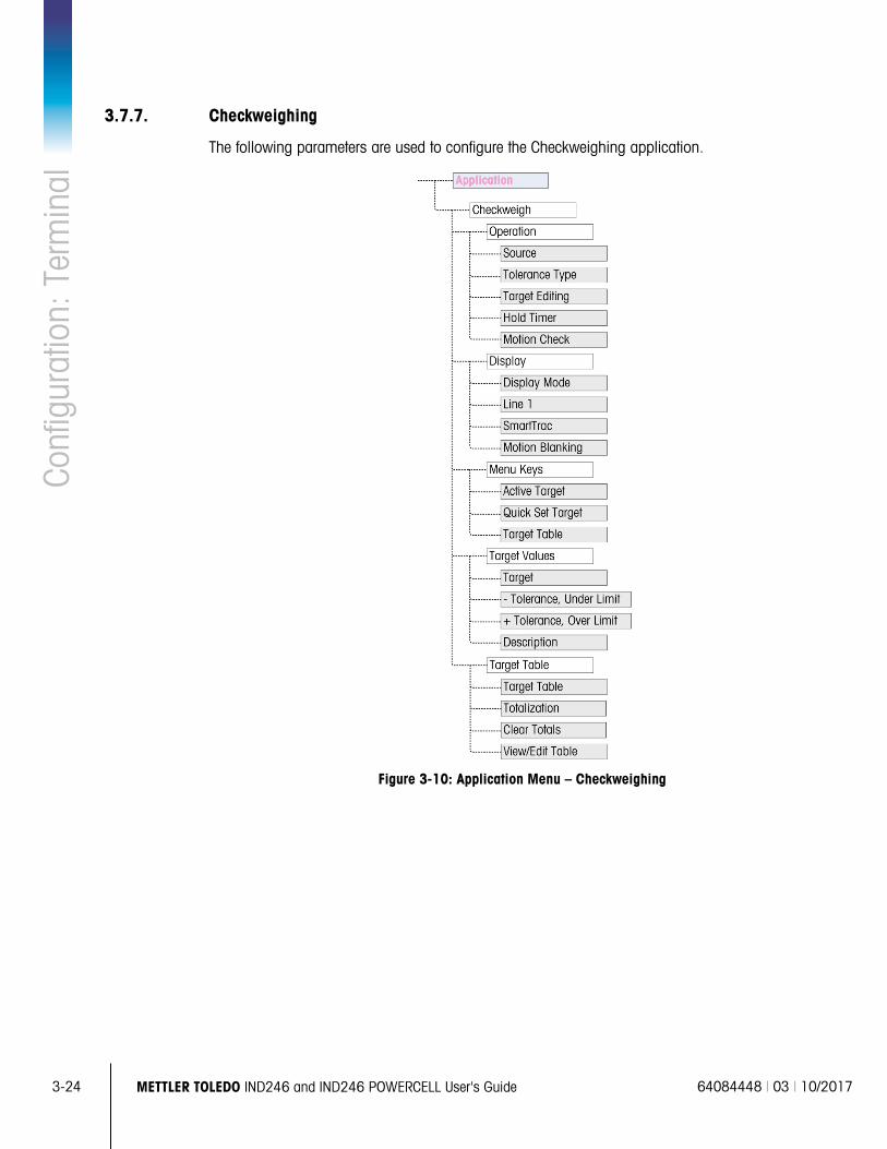
3-24
METTLER TOLEDO IND246 and IND246 POWERCELL User's Guide 64084448 | 03 | 10/2017
Conf
igur
atio
n: T
erm
inal
3.7.7. Checkweighing
The following parameters are used to configure the Checkweighing application.
Figure 3-10: Application Menu – Checkweighing
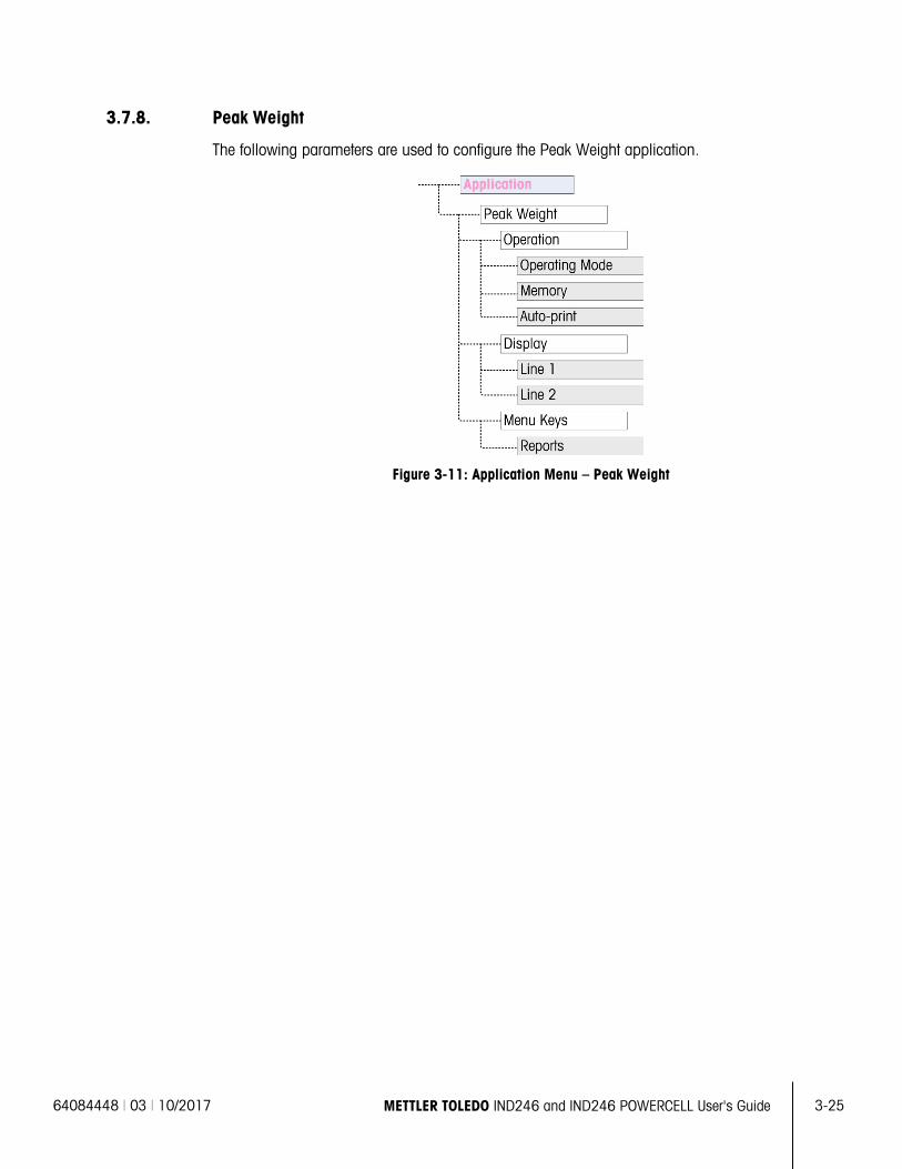
64084448 | 03 | 10/2017 METTLER TOLEDO IND246 and IND246 POWERCELL User's Guide
3-25
3.7.8. Peak Weight
The following parameters are used to configure the Peak Weight application.
Figure 3-11: Application Menu – Peak Weight
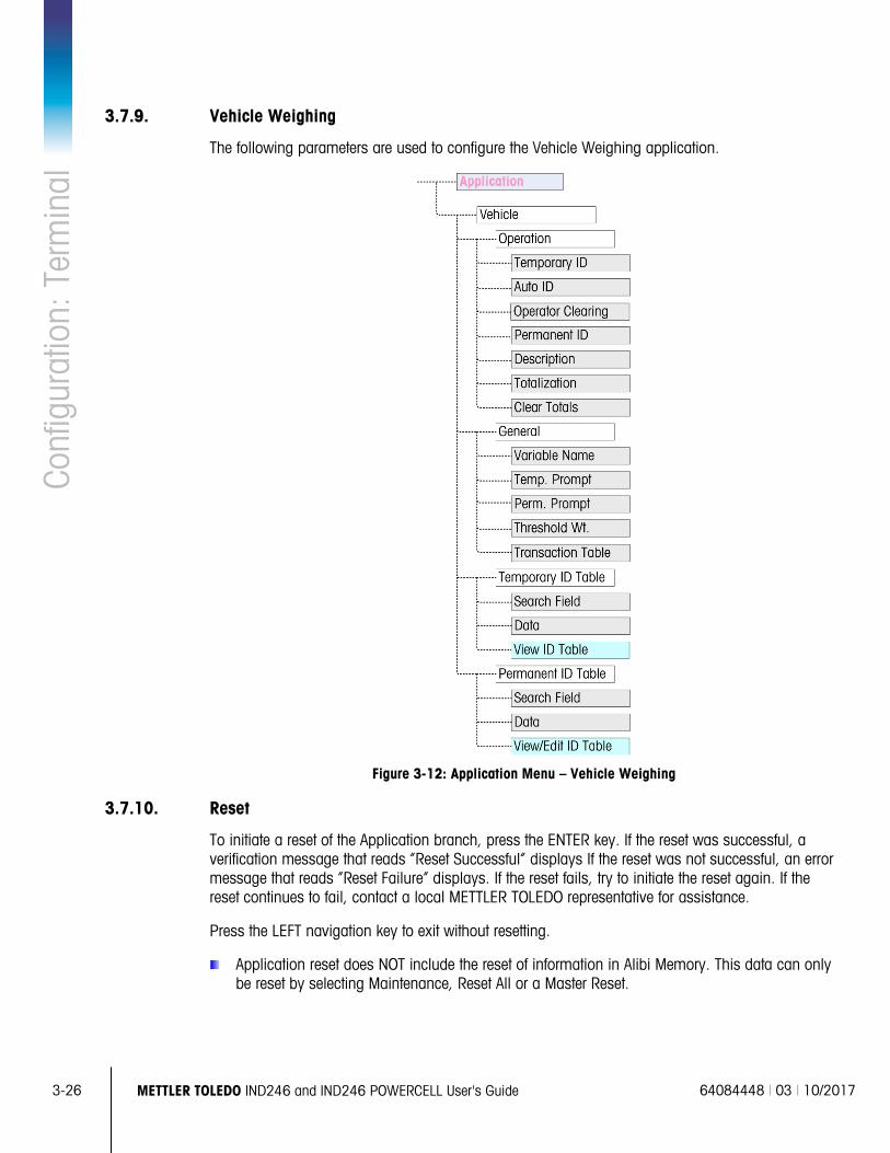
3-26
METTLER TOLEDO IND246 and IND246 POWERCELL User's Guide 64084448 | 03 | 10/2017
Conf
igur
atio
n: T
erm
inal
3.7.9. Vehicle Weighing
The following parameters are used to configure the Vehicle Weighing application.
Figure 3-12: Application Menu – Vehicle Weighing
3.7.10. Reset
To initiate a reset of the Application branch, press the ENTER key. If the reset was successful, a verification message that reads “Reset Successful” displays If the reset was not successful, an error message that reads “Reset Failure” displays. If the reset fails, try to initiate the reset again. If the reset continues to fail, contact a local METTLER TOLEDO representative for assistance.
Press the LEFT navigation key to exit without resetting.
Application reset does NOT include the reset of information in Alibi Memory. This data can only be reset by selecting Maintenance, Reset All or a Master Reset.
64084448 | 03 | 10/2017 METTLER TOLEDO IND246 and IND246 POWERCELL User's Guide
3-27
3.8. Configuration: Terminal 3.8.1. Device
The Device setup screen enables the entry of the terminal’s serial number and the keypad timeout value.
3.8.1.1. Serial Number
Use the alphanumeric keys to enter the terminal’s serial number. The serial number is located on the data label on the back of the terminal. Press the ENTER key to accept the serial number entered.
3.8.1.2. Key Timing
Use the numeric keys to enter the timeout period, in 100 mS increments, for key-presses when making alphanumeric data entry.
The value sets the amount of time that a letter shown on the display can be changed (e.g. from a to b to c) by pressing the key again. Once the Key Timing value has elapsed, the selected letter is set and the next key press will initiate a new character or digit entry.
Values between 3 and 12 are normal. The shorter the time, the faster an entry can occur. The default value is 8.
3.8.2. Display
Use the Display setup screen to set the screensaver and backlight timeouts, the auto off timer, what appears in the system line, select the tare display and adjust contrast of the display.
3.8.2.1. Screensaver
Select the number of minutes (1, 5, 10 or 30) that must elapse with no scale motion and no keypad activity before the screensaver is shown (replaces the view on the display screen). If motion is detected or any key is pressed, the screen saver automatically exits and its time is reset. A keystroke used to exit the screen saver mode is ignored for all other purposes.
A setting of Disabled in the Screensaver field will disable the screensaver.
3.8.2.2. Backlight Timeout
This parameter selects the amount of time that the backlight will stay “On” after no-motion is detected and no keys are pressed. Select between Always On, Disabled (always off), 1 minute, 5 minutes or 10 minutes.
3.8.2.3. Auto Off Timer
This feature helps conserve battery power by putting the terminal into a sleep mode by turning off the display after a certain amount of time has passed with no-motion and no key presses. Selections are Disabled (default), 10 minutes, 30 minutes and 60 minutes. If this field is disabled, the terminal will never turn itself off automatically.
3-28
METTLER TOLEDO IND246 and IND246 POWERCELL User's Guide 64084448 | 03 | 10/2017
Conf
igur
atio
n: T
erm
inal
3.8.2.4. System Line
The system line is the top line of the display above the weight display. This step allows selection of what will be shown in the system line during normal operation. Choose between Blank, Discrete I/O status, Time and Date or Both Discrete I/O and Time and Date.
3.8.2.5. Tare Display
This step selects if the tare value will be shown below and to the left of the normal weight field when in the net mode. The selections are Disabled, When Active and Always. If Active is selected, the tare area on the display will be shown only after a tare has been taken and will be blank when the terminal is in the gross mode. If Always is selected, when no tare is present, the tare display will indicate a 0 tare value in the tare display area.
3.8.2.6. Adjust Contrast
This parameter accesses a screen where the display contrast can be adjusted. Press the UP navigation key to increase the contrast and the DOWN navigation key to decrease the contrast. Press the LEFT navigation key to exit the adjustment.
3.8.3. Region
The region setup screens enable configuration of the time and date forma, the actual time and date values and language selection.
3.8.3.1. Format Time & Date
Selection boxes on this setup screen enable formatting of:
3.8.3.1.1. Time Format
12:MM (12-hour clock with hour and minutes displayed)
12:MM:SS (12-hour clock with hour, minutes, and seconds displayed)
24:MM (24-hour clock with hour and minutes displayed)
24:MM:SS (24-hour clock with hour, minutes, and seconds displayed)
3.8.3.1.2. Date Format
DD MM YY (Two-digit day, month, year)
DD MMM YYYY (Two-digit day, three-character month, four-digit year)
MM DD YY (Two-digit month, day, year)
MMM DD YYYY (Three-character month, two-digit day, four-digit year)
YY MM DD (Two-digit year, month, day)
YYYY MMM DD (Four-digit year, three-character month, two-digit day)
3.8.3.1.3. Date Field Separator
/ (slash)
- (dash)
. (period)
64084448 | 03 | 10/2017 METTLER TOLEDO IND246 and IND246 POWERCELL User's Guide
3-29
(space)
None
3.8.3.2. Set Time & Date
Enter the hour, minutes, day, month, and year on this setup screen’s text fields and selection boxes. The terminal automatically adjusts the date for a leap year, and a battery backup maintains the time and date settings in the event of a power outage.
Manual setting of the time is necessary for daylight savings time adjustments.
3.8.3.2.1. Hour
Use the numeric keypad to enter the hour in the Hour field text box. If a 12 hour format was selected, use the AM/PM selection box to select AM or PM. The AM/PM selection box only displays if the time format is set to 12:MM or 12:MM:SS on the Format Time & Date setup.
3.8.3.2.2. Minutes
Use the numeric keypad to enter the minutes in the Minutes field text box.
3.8.3.2.3. Day
Use the numeric keypad to enter the day in the Day field text box.
3.8.3.2.4. Month
Use the Month selection box to select the month.
3.8.3.2.5. Year
Use the numeric keypad to enter the year in the Year field text box.
3.8.3.3. Language
Use the Language setup screen to specify the language for terminal operations.
3.8.3.3.1. Menu Language
Use the Menu Language selection box to select the language for the operator menu and messages that display on the terminal. Choices are:
• English • German
• “F” Codes • Italian
• French • Spanish
3.8.3.3.2. Setup Language
Use the Setup Language selection box to select the language to be used when the terminal is in the setup mode. If F-codes is selected, each setup parameter label will be replaced with an equivalent numeric code. Refer to Appendix B for a list of the F-code values. Choices are:
• English
• F-codes
3-30
METTLER TOLEDO IND246 and IND246 POWERCELL User's Guide 64084448 | 03 | 10/2017
Conf
igur
atio
n: T
erm
inal
3.8.4. Transaction Counter
The transaction counter is a seven-digit register that tracks the total transactions that are completed on the terminal. When the value reaches 9,999,999, the next transaction causes a roll-over to 0000001. Use the Transaction Counter setup screen to configure transaction counter operations.
3.8.4.1. Transaction Counter
Use the Transaction Counter selection box to Enable or Disable the transaction counter.
3.8.4.2. Edit Counter
Use the Edit Counter selection box to Enable or Disable manual editing of the next transaction counter value.
3.8.4.3. Next Transaction
The value for the counter for the next transaction displays in the Next Transaction field. If Edit Counter is Enabled, the counter can be manually preset to any valid number above 0.
3.8.5. User
The IND246 terminal supports password protection of the setup mode. All setup functions of the terminal will be available to all users via the SETUP icon in the Operator’s menu until password protection is enabled and a password is entered.
3.8.5.1. Password Protection
If Disabled (default), all areas of the terminal (including the setup mode) can be entered normally. If Enabled, a password code must be entered before access is granted to the setup mode.
3.8.5.2. Password
If password protection is enabled in the previous step, this parameter allows entry of the actual password for access. A numeric entry up to six digits in length can be entered.
3.8.5.3. Confirm Password
Confirm the password previously entered. If the password does not agree, it will not be accepted.
3.8.6. Menu Keys
This screen permits the addition or removal of icons from the terminal's operator menu screen. Two icons, INFORMATION RECALL and SETUP , are automatically placed in the menu and cannot be removed.
Access each field on this page to Enable or Disable each of the icons. The list includes:
• Alibi Memory • Time and Date
• Contrast Adjust • Totals Memory
• Transaction Counter • Expand x10
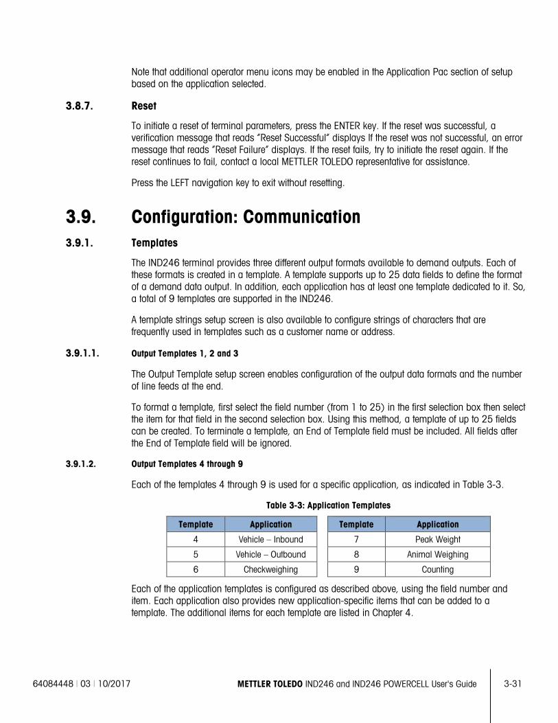
64084448 | 03 | 10/2017 METTLER TOLEDO IND246 and IND246 POWERCELL User's Guide
3-31
Note that additional operator menu icons may be enabled in the Application Pac section of setup based on the application selected.
3.8.7. Reset
To initiate a reset of terminal parameters, press the ENTER key. If the reset was successful, a verification message that reads “Reset Successful” displays If the reset was not successful, an error message that reads “Reset Failure” displays. If the reset fails, try to initiate the reset again. If the reset continues to fail, contact a local METTLER TOLEDO representative for assistance.
Press the LEFT navigation key to exit without resetting.
3.9. Configuration: Communication 3.9.1. Templates
The IND246 terminal provides three different output formats available to demand outputs. Each of these formats is created in a template. A template supports up to 25 data fields to define the format of a demand data output. In addition, each application has at least one template dedicated to it. So, a total of 9 templates are supported in the IND246.
A template strings setup screen is also available to configure strings of characters that are frequently used in templates such as a customer name or address.
3.9.1.1. Output Templates 1, 2 and 3
The Output Template setup screen enables configuration of the output data formats and the number of line feeds at the end.
To format a template, first select the field number (from 1 to 25) in the first selection box then select the item for that field in the second selection box. Using this method, a template of up to 25 fields can be created. To terminate a template, an End of Template field must be included. All fields after the End of Template field will be ignored.
3.9.1.2. Output Templates 4 through 9
Each of the templates 4 through 9 is used for a specific application, as indicated in Table 3-3.
Table 3-3: Application Templates
Template Application Template Application
4 Vehicle – Inbound 7 Peak Weight
5 Vehicle – Outbound 8 Animal Weighing
6 Checkweighing 9 Counting
Each of the application templates is configured as described above, using the field number and item. Each application also provides new application-specific items that can be added to a template. The additional items for each template are listed in Chapter 4.
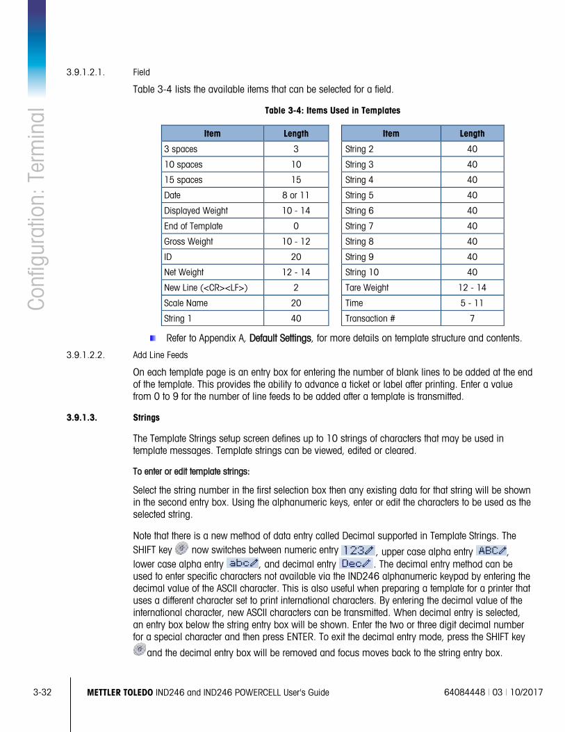
3-32
METTLER TOLEDO IND246 and IND246 POWERCELL User's Guide 64084448 | 03 | 10/2017
Conf
igur
atio
n: T
erm
inal
3.9.1.2.1. Field
Table 3-4 lists the available items that can be selected for a field.
Table 3-4: Items Used in Templates
Item Length Item Length
3 spaces 3 String 2 40
10 spaces 10 String 3 40
15 spaces 15 String 4 40
Date 8 or 11 String 5 40
Displayed Weight 10 - 14 String 6 40
End of Template 0 String 7 40
Gross Weight 10 - 12 String 8 40
ID 20 String 9 40
Net Weight 12 - 14 String 10 40
New Line (<CR><LF>) 2 Tare Weight 12 - 14
Scale Name 20 Time 5 - 11
String 1 40 Transaction # 7
Refer to Appendix A, Default Settings, for more details on template structure and contents.
3.9.1.2.2. Add Line Feeds
On each template page is an entry box for entering the number of blank lines to be added at the end of the template. This provides the ability to advance a ticket or label after printing. Enter a value from 0 to 9 for the number of line feeds to be added after a template is transmitted.
3.9.1.3. Strings
The Template Strings setup screen defines up to 10 strings of characters that may be used in template messages. Template strings can be viewed, edited or cleared.
To enter or edit template strings:
Select the string number in the first selection box then any existing data for that string will be shown in the second entry box. Using the alphanumeric keys, enter or edit the characters to be used as the selected string.
Note that there is a new method of data entry called Decimal supported in Template Strings. The SHIFT key now switches between numeric entry , upper case alpha entry , lower case alpha entry , and decimal entry . The decimal entry method can be used to enter specific characters not available via the IND246 alphanumeric keypad by entering the decimal value of the ASCII character. This is also useful when preparing a template for a printer that uses a different character set to print international characters. By entering the decimal value of the international character, new ASCII characters can be transmitted. When decimal entry is selected, an entry box below the string entry box will be shown. Enter the two or three digit decimal number for a special character and then press ENTER. To exit the decimal entry mode, press the SHIFT key
and the decimal entry box will be removed and focus moves back to the string entry box.
64084448 | 03 | 10/2017 METTLER TOLEDO IND246 and IND246 POWERCELL User's Guide
3-33
Note that decimal values from 32 to 255 can be entered. Control characters in decimal values 0 to 31 cannot be entered using this method. Control characters can be included in a template created using the InSite software. They will be recognized by the IND246 when the template is downloaded, and will be included in the template when it is printed
When entry is complete, press ENTER and focus will move back to String #. It is then possible to select another string to enter or edit.
3.9.2. Reports
The reports setup screen enables configuration of the structure of reports that are generated by the IND246 terminal. The reports setup screens include width, header, record separator and footer selections.
3.9.2.1. Width
Use the selection box for the Width field to select the width of the reports
• Narrow (40) – 40 character-wide reports • Wide (80) – 80 character-wide reports
3.9.2.2. Header
The Header field specifies the number of blank lines (CR/LF) to be placed at the start of each report.
3.9.2.3. Record Separator
A repeated character may be selected as a separator between printed records in the report. This step selects the character to be used. The character choices in the selection box are:
None (no separator between records) = (equal symbols)
* (asterisks) CR/LF (blank line)
- (dashes)
For example, if * (asterisks) is selected, the resulting line separator will appear as follows:
*************************************************************************
3.9.2.4. Footer
The Footer field specifies the number of blank lines (CR/LF) to be placed at the end of each report.
3.9.3. Connections
The connections setup provides a method to assign a function to a physical port in the terminal. The optional ports are only available if the appropriate option board has been installed.
Setup pages are available for the COM1, COM2, USB and Ethernet ports in the IND246 terminal.
These screens define what type of communication will occur over each port. If no connections are programmed, there will not be any data communication on that port. Specific details of the different assignments can be found in Appendix D, Communications.
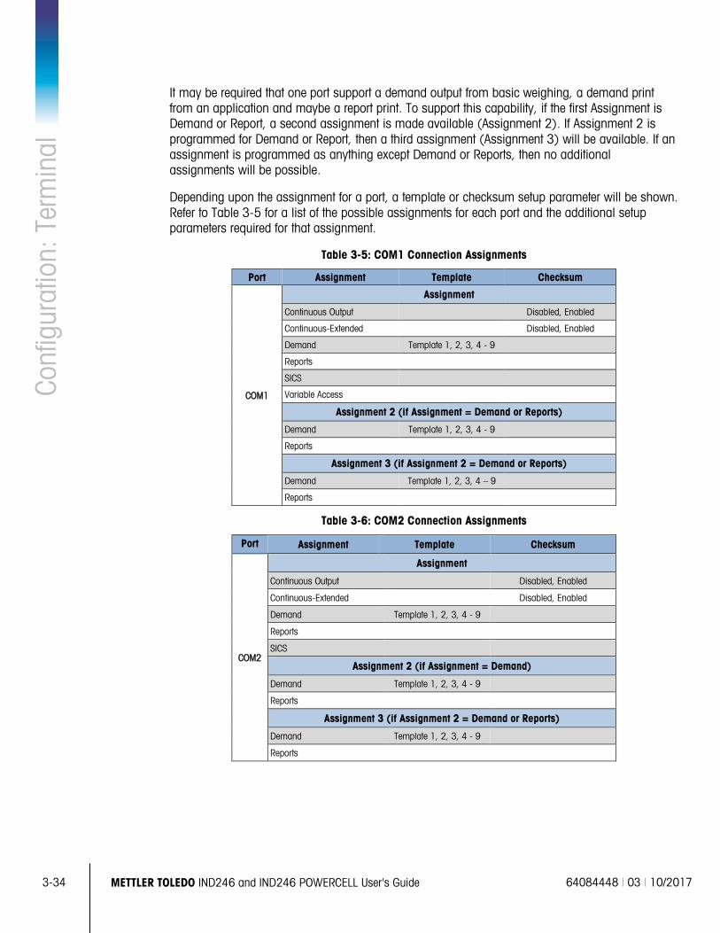
3-34
METTLER TOLEDO IND246 and IND246 POWERCELL User's Guide 64084448 | 03 | 10/2017
Conf
igur
atio
n: T
erm
inal
It may be required that one port support a demand output from basic weighing, a demand print from an application and maybe a report print. To support this capability, if the first Assignment is Demand or Report, a second assignment is made available (Assignment 2). If Assignment 2 is programmed for Demand or Report, then a third assignment (Assignment 3) will be available. If an assignment is programmed as anything except Demand or Reports, then no additional assignments will be possible.
Depending upon the assignment for a port, a template or checksum setup parameter will be shown. Refer to Table 3-5 for a list of the possible assignments for each port and the additional setup parameters required for that assignment.
Table 3-5: COM1 Connection Assignments
Port Assignment Template Checksum
COM1
Assignment
Continuous Output Disabled, Enabled
Continuous-Extended Disabled, Enabled
Demand Template 1, 2, 3, 4 - 9
Reports
SICS
Variable Access
Assignment 2 (if Assignment = Demand or Reports)
Demand Template 1, 2, 3, 4 - 9
Reports
Assignment 3 (if Assignment 2 = Demand or Reports)
Demand Template 1, 2, 3, 4 – 9
Reports
Table 3-6: COM2 Connection Assignments
Port Assignment Template Checksum
COM2
Assignment
Continuous Output Disabled, Enabled
Continuous-Extended Disabled, Enabled
Demand Template 1, 2, 3, 4 - 9
Reports
SICS
Assignment 2 (if Assignment = Demand)
Demand Template 1, 2, 3, 4 - 9
Reports
Assignment 3 (if Assignment 2 = Demand or Reports)
Demand Template 1, 2, 3, 4 - 9
Reports
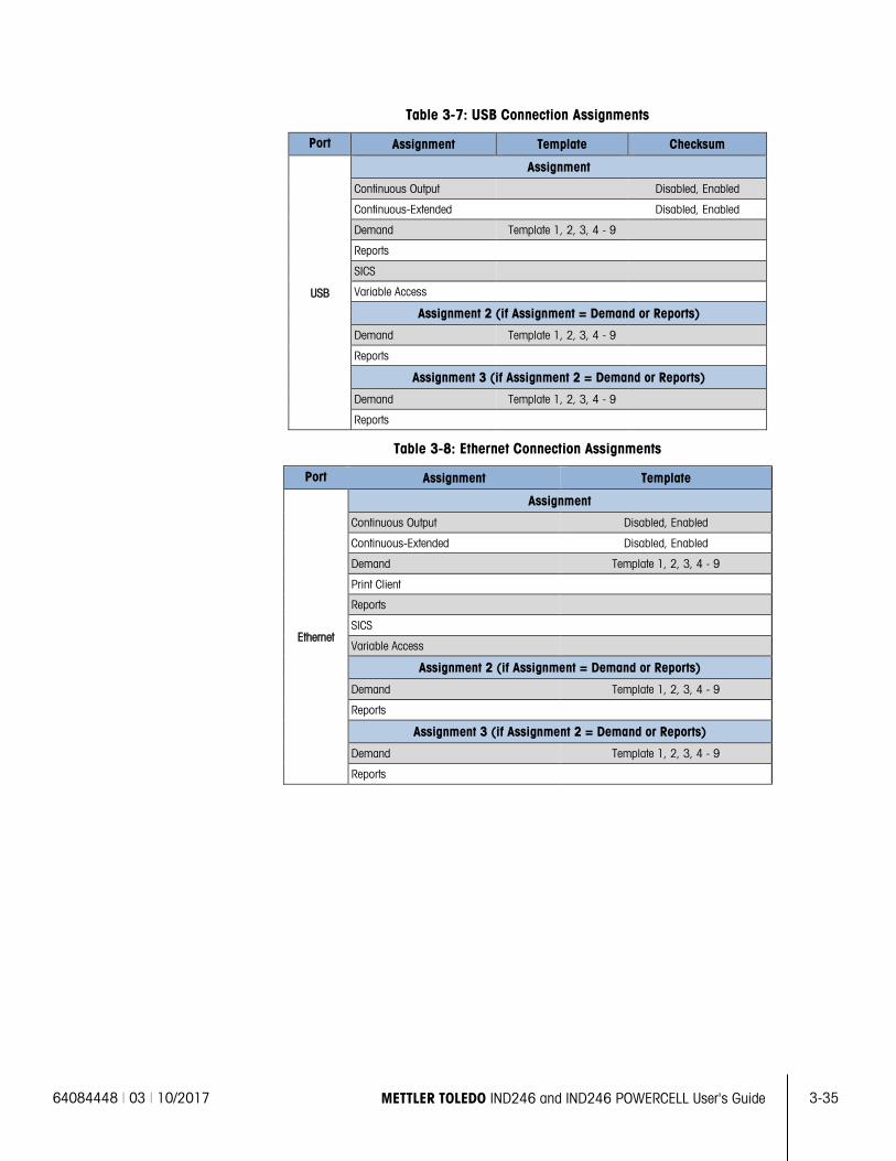
64084448 | 03 | 10/2017 METTLER TOLEDO IND246 and IND246 POWERCELL User's Guide
3-35
Table 3-7: USB Connection Assignments
Port Assignment Template Checksum
USB
Assignment
Continuous Output Disabled, Enabled
Continuous-Extended Disabled, Enabled
Demand Template 1, 2, 3, 4 - 9
Reports
SICS
Variable Access
Assignment 2 (if Assignment = Demand or Reports)
Demand Template 1, 2, 3, 4 - 9
Reports
Assignment 3 (if Assignment 2 = Demand or Reports)
Demand Template 1, 2, 3, 4 - 9
Reports
Table 3-8: Ethernet Connection Assignments
Port Assignment Template
Ethernet
Assignment
Continuous Output Disabled, Enabled
Continuous-Extended Disabled, Enabled
Demand Template 1, 2, 3, 4 - 9
Print Client
Reports
SICS
Variable Access
Assignment 2 (if Assignment = Demand or Reports)
Demand Template 1, 2, 3, 4 - 9
Reports
Assignment 3 (if Assignment 2 = Demand or Reports)
Demand Template 1, 2, 3, 4 - 9
Reports
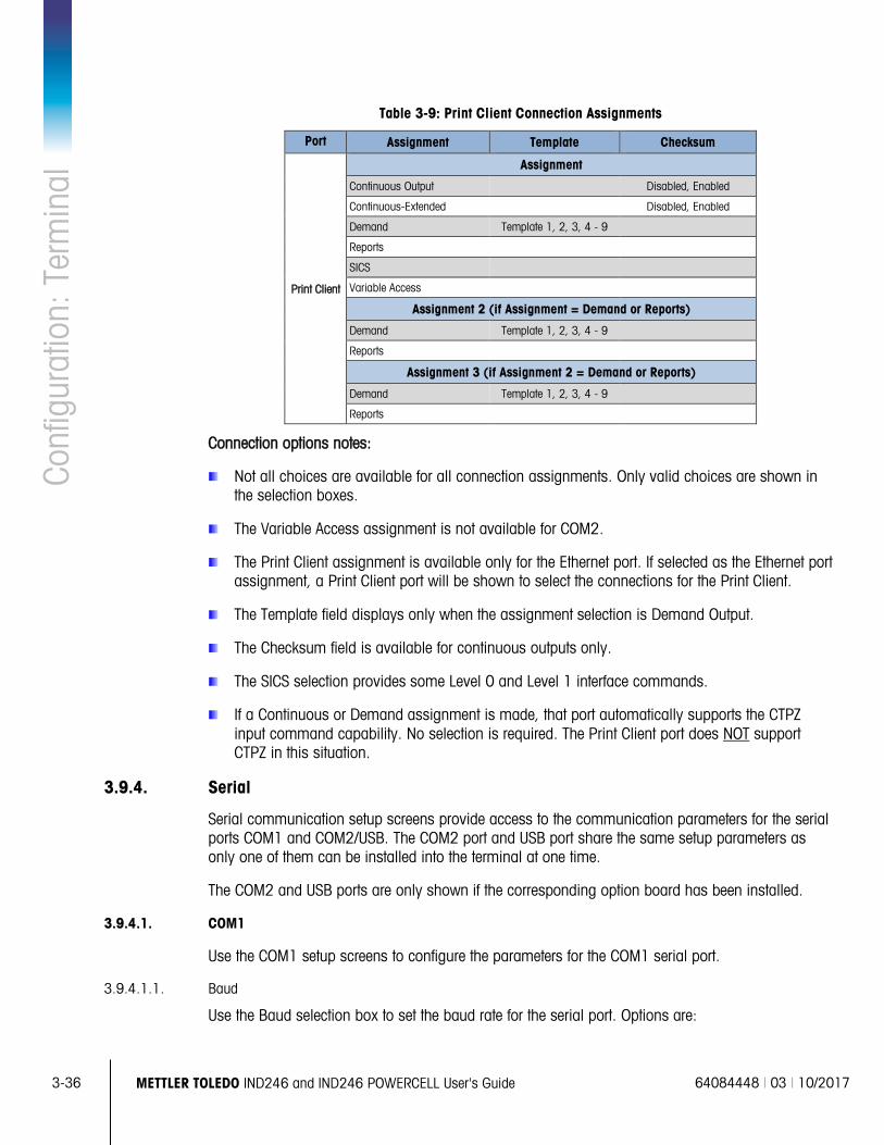
3-36
METTLER TOLEDO IND246 and IND246 POWERCELL User's Guide 64084448 | 03 | 10/2017
Conf
igur
atio
n: T
erm
inal
Table 3-9: Print Client Connection Assignments
Port Assignment Template Checksum
Print Client
Assignment
Continuous Output Disabled, Enabled
Continuous-Extended Disabled, Enabled
Demand Template 1, 2, 3, 4 - 9
Reports
SICS
Variable Access
Assignment 2 (if Assignment = Demand or Reports)
Demand Template 1, 2, 3, 4 - 9
Reports
Assignment 3 (if Assignment 2 = Demand or Reports)
Demand Template 1, 2, 3, 4 - 9
Reports
Connection options notes:
Not all choices are available for all connection assignments. Only valid choices are shown in the selection boxes.
The Variable Access assignment is not available for COM2.
The Print Client assignment is available only for the Ethernet port. If selected as the Ethernet port assignment, a Print Client port will be shown to select the connections for the Print Client.
The Template field displays only when the assignment selection is Demand Output.
The Checksum field is available for continuous outputs only.
The SICS selection provides some Level 0 and Level 1 interface commands.
If a Continuous or Demand assignment is made, that port automatically supports the CTPZ input command capability. No selection is required. The Print Client port does NOT support CTPZ in this situation.
3.9.4. Serial
Serial communication setup screens provide access to the communication parameters for the serial ports COM1 and COM2/USB. The COM2 port and USB port share the same setup parameters as only one of them can be installed into the terminal at one time.
The COM2 and USB ports are only shown if the corresponding option board has been installed.
3.9.4.1. COM1
Use the COM1 setup screens to configure the parameters for the COM1 serial port.
3.9.4.1.1. Baud
Use the Baud selection box to set the baud rate for the serial port. Options are:
64084448 | 03 | 10/2017 METTLER TOLEDO IND246 and IND246 POWERCELL User's Guide
3-37
300 1200 4800 19200 57600
600 2400 9600 38400 115200
3.9.4.1.2. Data Bits
Use the Data Bits selection box to set the data bits to either 7 or 8 for the serial port.
3.9.4.1.3. Parity
Use the Parity selection box to set the parity to None, Odd, or Even for the serial port.
3.9.4.1.4. Flow Control
Use the Flow Control selection box to set the flow control to either None or XON-XOFF (software handshaking).
After an XOFF command is received on COM1 configured for XON/XOFF handshaking, data remaining in the port’s output buffer will still be sent. The COM1 port buffer contains a maximum of 16 bytes of data.
3.9.4.1.5. Interface
Use the Interface selection box to select the serial port interface. For the standard IND246 terminal COM1 provides an RS-232 interface only. For the IND246 POWERCELL terminal there is a choice of a RS-232, RS-422 or RS-485 interface.
3.9.4.2. COM2/USB
Use the COM2/USB setup screens to configure the parameters for the COM2 and USB ports.
3.9.4.2.1. Baud
Use the Baud selection box to set the baud rate for the serial port. Options are:
300 1200 4800 19200 57600
600 2400 9600 38400 115200
3.9.4.2.2. Data Bits
Use the Data Bits selection box to set the data bits to either 7 or 8 for the serial port.
3.9.4.2.3. Parity
Use the Parity selection box to set the parity to None, Odd, or Even for the serial port.
3.9.4.2.4. Flow Control
Use the Flow Control selection box to set the flow control to either None or XON-XOFF (software handshaking).
After an XOFF command is received on COM2 configured for XON/XOFF handshaking, data remaining in the port’s output buffer will still be sent. The COM2 port buffer contains a maximum of 64 bytes of data.
3.9.4.2.5. Interface
Use the Interface selection box to select the serial port interface. Selections for COM2 include either RS-232 or RS-485. This parameter is not shown for the USB option.
3-38
METTLER TOLEDO IND246 and IND246 POWERCELL User's Guide 64084448 | 03 | 10/2017
Conf
igur
atio
n: T
erm
inal
3.9.5. Network
Network setup screens include Ethernet and Print Client.
3.9.5.1. Ethernet
Ethernet is available for transfer of data, connecting to InSite™, variable access and connection to a Print Client. Setup for Ethernet allows static Internet Protocol (IP) addressing only.
The Ethernet branch includes the following fields:
3.9.5.1.1. MAC Address
The Medium Access Control (MAC) Address cannot be edited; it is shown for information only.
3.9.5.1.2. DHCP Client
The DHCP (Dynamic Host Configuration Protocol) client can be Enabled or Disabled. If the DHCP Client setting is enabled, the IP Address, Subnet Mask, and Gateway Address fields are assigned automatically by the network and become read-only in the setup screens. If disabled, the IP address must manually be assigned in the following fields.
3.9.5.1.3. IP Address
Enter the IP address (or view if DHCP Client is enabled) for the IND246 terminal. After each group of digits has been entered, press ENTER to proceed to the next group. The default value for the IP is 192.168.000.001.
3.9.5.1.4. Subnet Mask
Enter the subnet mask (or view if DHCP Client is enabled) for the IND246 terminal. After each group of digits has been entered, press ENTER to proceed to the next group. The default value for the subnet mask is 255.255.255.0.
3.9.5.1.5. Gateway Address
Enter the gateway address (or view if DHCP Client is enabled) for the IND246 terminal. After each group of digits has been entered, press ENTER to proceed to the next group. The default value for the gateway is blank.
After entry is complete, press the LEFT navigation key to return to the setup menu
3.9.5.2. Print Client
The Print Client connection allows the IND246 to send data to a network device such as a printer. The Print Client configuration is only shown if a print client connection was created at Communication > Connections > Ethernet.
3.9.5.2.1. Server IP Address
The Server IP Address is the IP address of the network device (usually a printer) where the terminal will send the print information. Enter the IP address using the numeric keypad.
3.9.5.2.2. Server TCP Port
Enter the Server TCP Port of the device on the network. This is the port on the network device through which communication is established.
64084448 | 03 | 10/2017 METTLER TOLEDO IND246 and IND246 POWERCELL User's Guide
3-39
3.9.6. Reset
To initiate a reset of the Communication block of setup, press the ENTER key. If the reset was successful, a verification message that reads “Reset Successful” displays If the reset was not successful, an error message that reads “Reset Failure” displays. If the reset fails, try to initiate the reset again. If the reset continues to fail, contact a local METTLER TOLEDO representative for assistance.
Press the LEFT navigation key to exit without resetting.
3.10. Configuration: Maintenance 3.10.1. Diagnostics
3.10.1.1. Display Test
The Display Test screen displays all dots “on” when first accessed. After three seconds, all dots turn “off”. This cycle will continue until the LEFT navigation key is pressed to return to the menu.
3.10.1.2. Keyboard Test
The Keyboard Test screen enables testing of the terminal keys, including Scale function keys, Navigation keys and Numeric keys.
Press any key and the screen will display a graphic for that key. When testing is complete, press the LEFT navigation key to return to the menu.
3.10.2. Scale
Scale diagnostics setup screens include Load Cell Output, Calibration Values and Statistics.
3.10.2.1. Load Cell Output
The Load Cell Output screen displays the current number of counts (active value) for the scale. These are raw counts and do not take into consideration the zero or span factors.
Press the LEFT navigation key to return to the menu.
3.10.2.2. Calibration Values
The Calibration Values screen displays the current calibration values for the scale. The number of test loads that display calibration values is determined by the Linearity Adjustment setting configured for the scale (refer to Scale > Calibration).
These calibration values can be recorded and then manually entered into a new replacement board should a failure ever occur, which eliminates having to recalibrate the scale with test weights. While this method is quick, it is not as accurate as placing test weights on the scale.
Use the UP and DOWN navigation keys to select a calibration value to be modified. Use the numeric keypad to enter new values.
Press the LEFT navigation key to return to the menu.
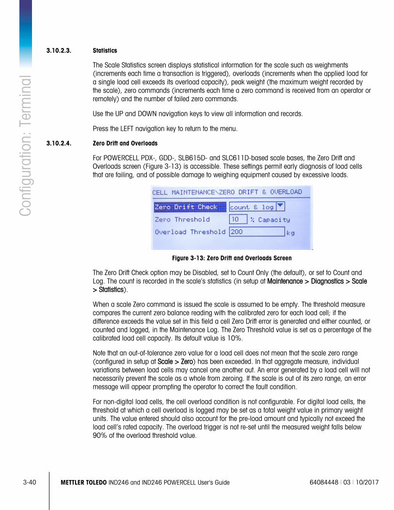
3-40
METTLER TOLEDO IND246 and IND246 POWERCELL User's Guide 64084448 | 03 | 10/2017
Conf
igur
atio
n: T
erm
inal
3.10.2.3. Statistics
The Scale Statistics screen displays statistical information for the scale such as weighments (increments each time a transaction is triggered), overloads (increments when the applied load for a single load cell exceeds its overload capacity), peak weight (the maximum weight recorded by the scale), zero commands (increments each time a zero command is received from an operator or remotely) and the number of failed zero commands.
Use the UP and DOWN navigation keys to view all information and records.
Press the LEFT navigation key to return to the menu.
3.10.2.4. Zero Drift and Overloads
For POWERCELL PDX-, GDD-, SLB615D- and SLC611D-based scale bases, the Zero Drift and Overloads screen (Figure 3-13) is accessible. These settings permit early diagnosis of load cells that are failing, and of possible damage to weighing equipment caused by excessive loads.
Figure 3-13: Zero Drift and Overloads Screen
The Zero Drift Check option may be Disabled, set to Count Only (the default), or set to Count and Log. The count is recorded in the scale’s statistics (in setup at Maintenance > Diagnostics > Scale > Statistics).
When a scale Zero command is issued the scale is assumed to be empty. The threshold measure compares the current zero balance reading with the calibrated zero for each load cell; if the difference exceeds the value set in this field a cell Zero Drift error is generated and either counted, or counted and logged, in the Maintenance Log. The Zero Threshold value is set as a percentage of the calibrated load cell capacity. Its default value is 10%.
Note that an out-of-tolerance zero value for a load cell does not mean that the scale zero range (configured in setup at Scale > Zero) has been exceeded. In that aggregate measure, individual variations between load cells may cancel one another out. An error generated by a load cell will not necessarily prevent the scale as a whole from zeroing. If the scale is out of its zero range, an error message will appear prompting the operator to correct the fault condition.
For non-digital load cells, the cell overload condition is not configurable. For digital load cells, the threshold at which a cell overload is logged may be set as a total weight value in primary weight units. The value entered should also account for the pre-load amount and typically not exceed the load cell’s rated capacity. The overload trigger is not re-set until the measured weight falls below 90% of the overload threshold value.
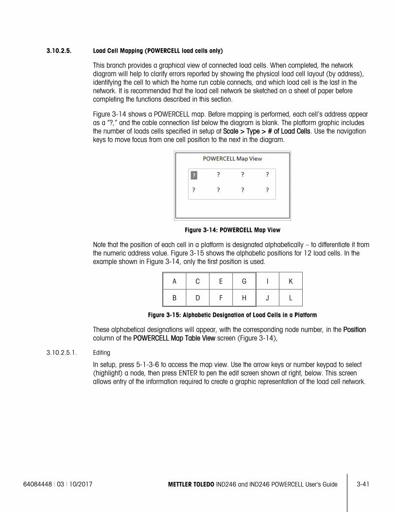
64084448 | 03 | 10/2017 METTLER TOLEDO IND246 and IND246 POWERCELL User's Guide
3-41
3.10.2.5. Load Cell Mapping (POWERCELL load cells only)
This branch provides a graphical view of connected load cells. When completed, the network diagram will help to clarify errors reported by showing the physical load cell layout (by address), identifying the cell to which the home run cable connects, and which load cell is the last in the network. It is recommended that the load cell network be sketched on a sheet of paper before completing the functions described in this section.
Figure 3-14 shows a POWERCELL map. Before mapping is performed, each cell’s address appear as a “?,” and the cable connection list below the diagram is blank. The platform graphic includes the number of loads cells specified in setup at Scale > Type > # of Load Cells. Use the navigation keys to move focus from one cell position to the next in the diagram.
Figure 3-14: POWERCELL Map View
Note that the position of each cell in a platform is designated alphabetically – to differentiate it from the numeric address value. Figure 3-15 shows the alphabetic positions for 12 load cells. In the example shown in Figure 3-14, only the first position is used.
A C E G I K
B D F H J L
Figure 3-15: Alphabetic Designation of Load Cells in a Platform
These alphabetical designations will appear, with the corresponding node number, in the Position column of the POWERCELL Map Table View screen (Figure 3-14),
3.10.2.5.1. Editing
In setup, press 5-1-3-6 to access the map view. Use the arrow keys or number keypad to select (highlight) a node, then press ENTER to pen the edit screen shown at right, below. This screen allows entry of the information required to create a graphic representation of the load cell network.
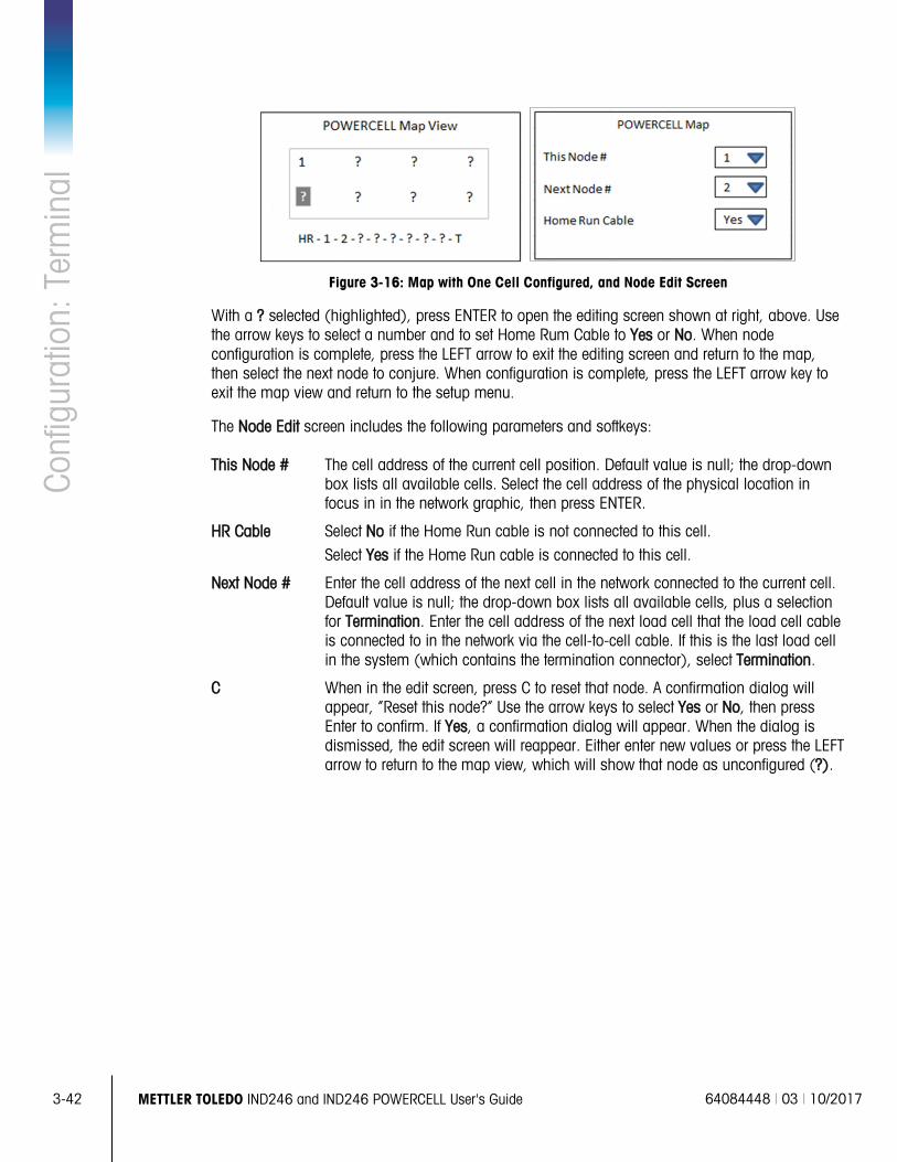
3-42
METTLER TOLEDO IND246 and IND246 POWERCELL User's Guide 64084448 | 03 | 10/2017
Conf
igur
atio
n: T
erm
inal
Figure 3-16: Map with One Cell Configured, and Node Edit Screen
With a ? selected (highlighted), press ENTER to open the editing screen shown at right, above. Use the arrow keys to select a number and to set Home Rum Cable to Yes or No. When node configuration is complete, press the LEFT arrow to exit the editing screen and return to the map, then select the next node to conjure. When configuration is complete, press the LEFT arrow key to exit the map view and return to the setup menu.
The Node Edit screen includes the following parameters and softkeys:
This Node # The cell address of the current cell position. Default value is null; the drop-down box lists all available cells. Select the cell address of the physical location in focus in in the network graphic, then press ENTER.
HR Cable Select No if the Home Run cable is not connected to this cell. Select Yes if the Home Run cable is connected to this cell.
Next Node # Enter the cell address of the next cell in the network connected to the current cell. Default value is null; the drop-down box lists all available cells, plus a selection for Termination. Enter the cell address of the next load cell that the load cell cable is connected to in the network via the cell-to-cell cable. If this is the last load cell in the system (which contains the termination connector), select Termination.
C When in the edit screen, press C to reset that node. A confirmation dialog will appear, “Reset this node?” Use the arrow keys to select Yes or No, then press Enter to confirm. If Yes, a confirmation dialog will appear. When the dialog is dismissed, the edit screen will reappear. Either enter new values or press the LEFT arrow to return to the map view, which will show that node as unconfigured (?).
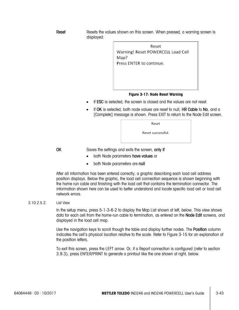
64084448 | 03 | 10/2017 METTLER TOLEDO IND246 and IND246 POWERCELL User's Guide
3-43
Reset Resets the values shown on this screen. When pressed, a warning screen is displayed:
Figure 3-17: Node Reset Warning
• If ESC is selected, the screen is closed and the values are not reset.
• If OK is selected, both node values are reset to null, HR Cable to No, and a [Complete] message is shown. Press EXIT to return to the Node Edit screen.
OK Saves the settings and exits the screen, only if • both Node parameters have values or
• both Node parameters are null
After all information has been entered correctly, a graphic describing each load cell address position displays. Below the graphic, the load cell connection sequence is shown beginning with the home run cable and finishing with the load cell that contains the termination connector. The information shown here can be used to better understand and locate specific load cell or load cell network errors.
3.10.2.5.2. List View
In the setup menu, press 5-1-3-6-2 to display the Map List shown at left, below. This view shows data for each cell from the home-run cable to termination, as entered on the Node Edit screens, and displayed in the load cell map.
Use the navigation keys to scroll though the table and display further nodes. The Position column indicates the cell’s physical location relative to the scale. Refer to Figure 3-15 for an explanation of the position letters.
To exit this screen, press the LEFT arrow. Or, if a Report connection is configured (refer to section 3.9.3), press ENTER/PRINT to generate a printout like the one shown at right, below.
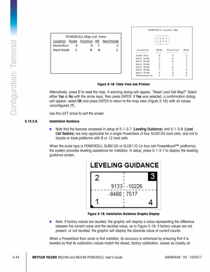
3-44
METTLER TOLEDO IND246 and IND246 POWERCELL User's Guide 64084448 | 03 | 10/2017
Conf
igur
atio
n: T
erm
inal
Figure 3-18: Table View and Printout
Alternatively, press C to reset the map. A warning dialog will appear, “Reset Load Cell Map?” Select either Yes or No with the arrow keys, then press ENTER. If Yes was selected, a confirmation dialog will appear; select OK and press ENTER to return to the map view (Figure 3-16) with all values unconfigured (?).
Use the LEFT arrow to exit the screen.
3.10.2.6. Installation Guidance
Note that the features accessed in setup at 5-1-3-7 (Leveling Guidance) and 5-1-3-8 (Load Cell Restore) are only applicable for a single PowerDeck of four SLC615D load cells, and not to double or triple platforms with 8 or 12 load cells.
When the scale type is POWERCELL SLB615D or SLC611D (in four-cell PowerMount™ platforms), the system provides leveling assistance for installers. In setup, press 5-1-3-7 to display the leveling guidance screen.
Figure 3-19: Installation Guidance Graphic Display
Note: If factory values are recalled, the graphic will display a value representing the difference between the current value and the recalled value, as in Figure 3-19. If factory values are not present, or not recalled, the graphic will display the absolute value of current counts.
When a PowerDeck floor scale is first installed, its accuracy is enhanced by ensuring that it is levelled so that its calibration values match the stored, factory calibration, values as closely as
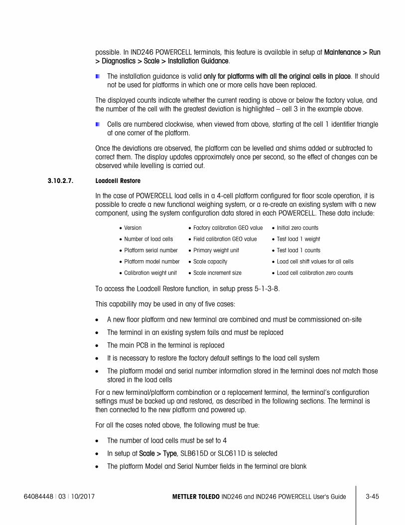
64084448 | 03 | 10/2017 METTLER TOLEDO IND246 and IND246 POWERCELL User's Guide
3-45
possible. In IND246 POWERCELL terminals, this feature is available in setup at Maintenance > Run > Diagnostics > Scale > Installation Guidance.
The installation guidance is valid only for platforms with all the original cells in place. It should not be used for platforms in which one or more cells have been replaced.
The displayed counts indicate whether the current reading is above or below the factory value, and the number of the cell with the greatest deviation is highlighted – cell 3 in the example above.
Cells are numbered clockwise, when viewed from above, starting at the cell 1 identifier triangle at one corner of the platform.
Once the deviations are observed, the platform can be levelled and shims added or subtracted to correct them. The display updates approximately once per second, so the effect of changes can be observed while levelling is carried out.
3.10.2.7. Loadcell Restore
In the case of POWERCELL load cells in a 4-cell platform configured for floor scale operation, it is possible to create a new functional weighing system, or a re-create an existing system with a new component, using the system configuration data stored in each POWERCELL. These data include:
• Version • Factory calibration GEO value • Initial zero counts
• Number of load cells • Field calibration GEO value • Test load 1 weight
• Platform serial number • Primary weight unit • Test load 1 counts
• Platform model number • Scale capacity • Load cell shift values for all cells
• Calibration weight unit • Scale increment size • Load cell calibration zero counts
To access the Loadcell Restore function, in setup press 5-1-3-8.
This capability may be used in any of five cases:
• A new floor platform and new terminal are combined and must be commissioned on-site
• The terminal in an existing system fails and must be replaced
• The main PCB in the terminal is replaced
• It is necessary to restore the factory default settings to the load cell system
• The platform model and serial number information stored in the terminal does not match those stored in the load cells
For a new terminal/platform combination or a replacement terminal, the terminal’s configuration settings must be backed up and restored, as described in the following sections. The terminal is then connected to the new platform and powered up.
For all the cases noted above, the following must be true:
• The number of load cells must be set to 4
• In setup at Scale > Type, SLB615D or SLC611D is selected
• The platform Model and Serial Number fields in the terminal are blank
3-46
METTLER TOLEDO IND246 and IND246 POWERCELL User's Guide 64084448 | 03 | 10/2017
Conf
igur
atio
n: T
erm
inal
• At least two of the four cells have factory configuration data
• The terminal is not metrologically sealed
8. At start-up, the terminal confirms that load cell configuration data is present in each cell and validates the data.
9. The terminal then displays a confirmation dialog Use factory calibration?
10. If the operator selects Yes, the terminal displays a GEO code entry dialog, where the local GEO code is either displayed (if already configured in the terminal) for confirmation, or must be entered and confirmed.
11. Use the arrow keys to highlight START, then press ENTER to continue.
12. Once the GEO entry is confirmed, the terminal completes the configuration process. Selecting No aborts the process and continues the normal start-up sequence.
Once the system is complete, the platform must be levelled using the utility provided in setup at Maintenance > Run > Diagnostics > Scale > Installation Guidance.
3.10.2.8. Serial Test
The Serial Test screen enables testing of the sending and receiving hardware on the serial ports COM1 and COM2.
3.10.2.8.1. Port
Use the Port selection box to select the serial port for testing (1 or 2).
As soon as the port selection is entered, the test begins. To stop the test, change the port selection back to None or press the LEFT navigation key.
In the serial test mode, the terminal will transmit a string “Testing COMX nn” out the selected serial port where the "X" is the selected com port number (1 or 2) and “nn” is a sequential two-digit number (00–99). If a jumper is placed between the transmit and receive terminals on that port, the same data displays in the receiving field.
If another device is connected to the receiving port, any ASCII data received displays in the receiving field.
3.10.2.9. Discrete I/O Test
Discrete I/O Test setup screens include testing for both inputs and outputs.
VERY IMPORTANT!: When any of the Discrete I/O Test screens are first accessed, a warning message displays with instructions to remove output control power before proceeding with the test. The Discrete I/O Test screens enable manual setting of any of the outputs to on or off for testing, so it is necessary to remove output control power before proceeding.
Press the LEFT navigation key to abort and not perform the test.
To continue the test:
1. Press the ENTER key. A real-time display shows the status of each of the inputs and enables each of the outputs to be turned on and off. An input or output that displays is turned off. An input or an output that displays is turned on.
64084448 | 03 | 10/2017 METTLER TOLEDO IND246 and IND246 POWERCELL User's Guide
3-47
2. Use the LEFT and RIGHT navigation keys to select an output to turn on or off.
3. With an output in focus, press the DOWN navigation key to turn the output off, and press the UP navigation key to turn the output on.
4. Press the ENTER key to return to the menu. The outputs return to their previous on/off configuration before the tests were initiated.
3.10.3. Replace Battery
This step provides access to a sequence used to replace the coin cell battery used to back up RAM memory. Details of this procedure are described in the Technical Manual in the Maintenance chapter. It is recommended that an authorized METTLER TOLEDO service representative perform this service.
3.10.4. Install Software Update
This step is used to update the program in flash memory. Details of this procedure are described in the Technical Manual in the Maintenance chapter. It is recommended that an authorized METTLER TOLEDO service representative perform this service.
3.10.5. Backup to SD
The terminal will store all setup parameters and table data to the SD card. In case of a catastrophic failure, the saved file could then be restored to the terminal.
Details of this procedure are described in the Technical Manual in the Maintenance chapter. It is recommended that an authorized METTLER TOLEDO service representative perform this service.
3.10.6. Restore from SD
If a “Backup to SD” process has previously been triggered, this step retrieves the stored data from the SD card and writes the data back into the terminal.
Details of this procedure are described in the Technical Manual in the Maintenance chapter. It is recommended that an authorized METTLER TOLEDO service representative perform this service.
3.10.7. POWERCELL Maintenance
3.10.7.1. Performance Log
The Performance Log provides a summary of the performance and diagnostics data collected on a scale using POWERCELL PDX, GDD, SLB615D and SLC611D load cells. The log will hold approximately 1600 individual records before it begins over-writing the oldest entries. Note that the accumulation of data in the log depends on the number of cells in the system – each cell produces one record at each log interval.
Log Interval
Use the Log Interval entry box to enter a time interval in hours for the terminal to automatically record a set of data in the log. Valid entries are from 0 to 999.9. A value of 0 (default) disables the automatic logging. For day-to-day operation, 24 hours (default) is a typical value. When a scale is being tested, the interval can be reduced to collect data more frequently.
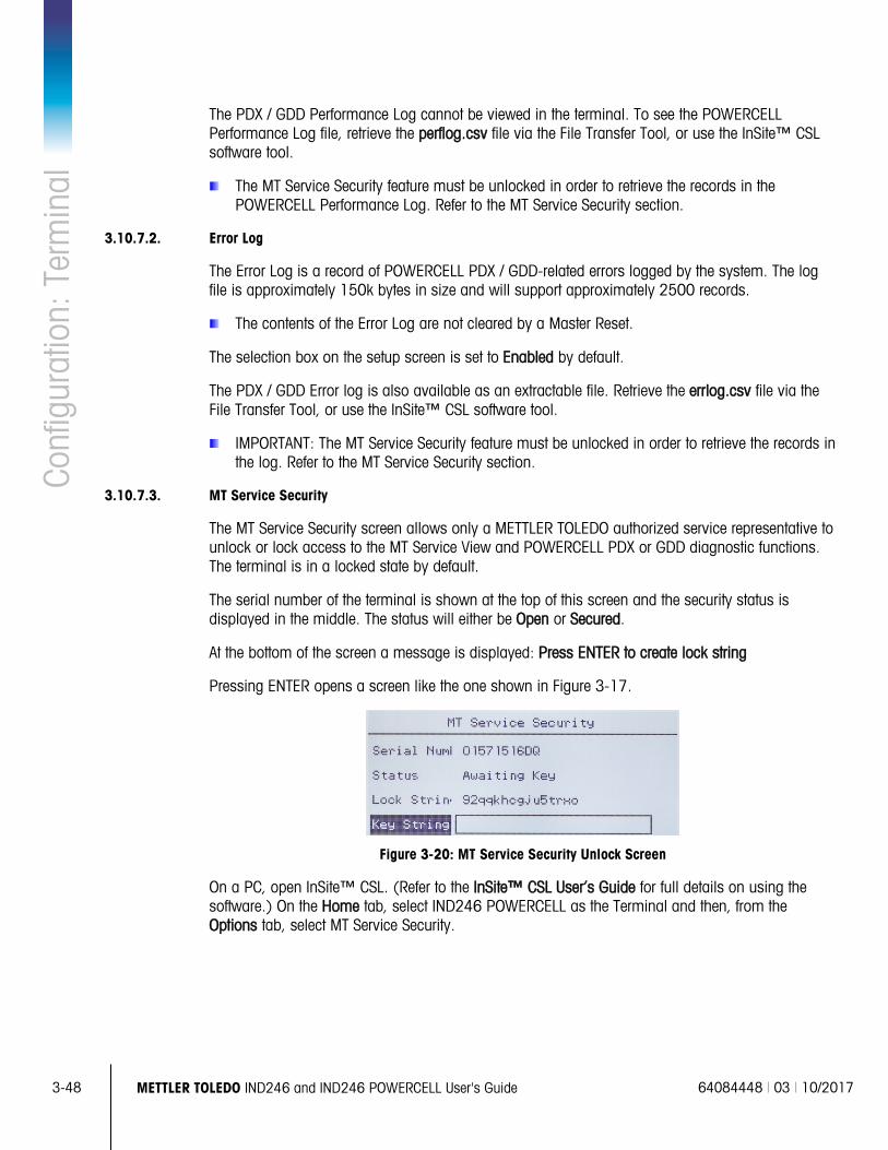
3-48
METTLER TOLEDO IND246 and IND246 POWERCELL User's Guide 64084448 | 03 | 10/2017
Conf
igur
atio
n: T
erm
inal
The PDX / GDD Performance Log cannot be viewed in the terminal. To see the POWERCELL Performance Log file, retrieve the perflog.csv file via the File Transfer Tool, or use the InSite™ CSL software tool.
The MT Service Security feature must be unlocked in order to retrieve the records in the POWERCELL Performance Log. Refer to the MT Service Security section.
3.10.7.2. Error Log
The Error Log is a record of POWERCELL PDX / GDD-related errors logged by the system. The log file is approximately 150k bytes in size and will support approximately 2500 records.
The contents of the Error Log are not cleared by a Master Reset.
The selection box on the setup screen is set to Enabled by default.
The PDX / GDD Error log is also available as an extractable file. Retrieve the errlog.csv file via the File Transfer Tool, or use the InSite™ CSL software tool.
IMPORTANT: The MT Service Security feature must be unlocked in order to retrieve the records in the log. Refer to the MT Service Security section.
3.10.7.3. MT Service Security
The MT Service Security screen allows only a METTLER TOLEDO authorized service representative to unlock or lock access to the MT Service View and POWERCELL PDX or GDD diagnostic functions. The terminal is in a locked state by default.
The serial number of the terminal is shown at the top of this screen and the security status is displayed in the middle. The status will either be Open or Secured.
At the bottom of the screen a message is displayed: Press ENTER to create lock string
Pressing ENTER opens a screen like the one shown in Figure 3-17.
Figure 3-20: MT Service Security Unlock Screen
On a PC, open InSite™ CSL. (Refer to the InSite™ CSL User’s Guide for full details on using the software.) On the Home tab, select IND246 POWERCELL as the Terminal and then, from the Options tab, select MT Service Security.
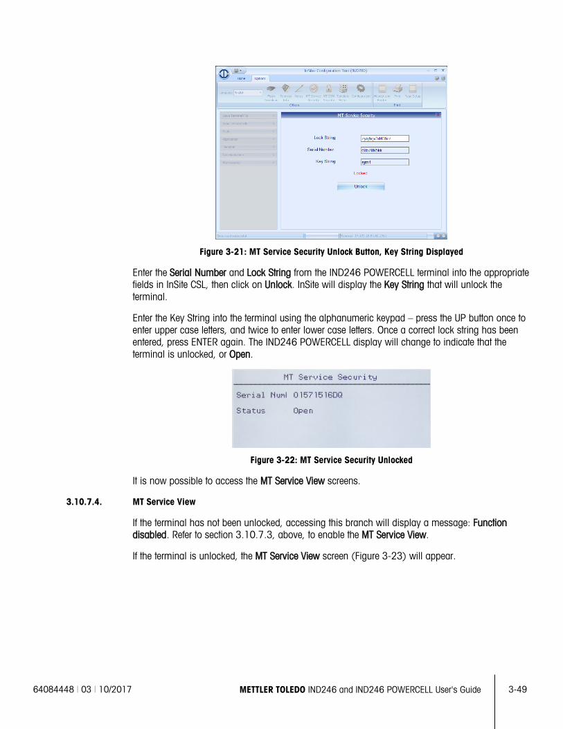
64084448 | 03 | 10/2017 METTLER TOLEDO IND246 and IND246 POWERCELL User's Guide
3-49
Figure 3-21: MT Service Security Unlock Button, Key String Displayed
Enter the Serial Number and Lock String from the IND246 POWERCELL terminal into the appropriate fields in InSite CSL, then click on Unlock. InSite will display the Key String that will unlock the terminal.
Enter the Key String into the terminal using the alphanumeric keypad – press the UP button once to enter upper case letters, and twice to enter lower case letters. Once a correct lock string has been entered, press ENTER again. The IND246 POWERCELL display will change to indicate that the terminal is unlocked, or Open.
Figure 3-22: MT Service Security Unlocked
It is now possible to access the MT Service View screens.
3.10.7.4. MT Service View
If the terminal has not been unlocked, accessing this branch will display a message: Function disabled. Refer to section 3.10.7.3, above, to enable the MT Service View.
If the terminal is unlocked, the MT Service View screen (Figure 3-23) will appear.
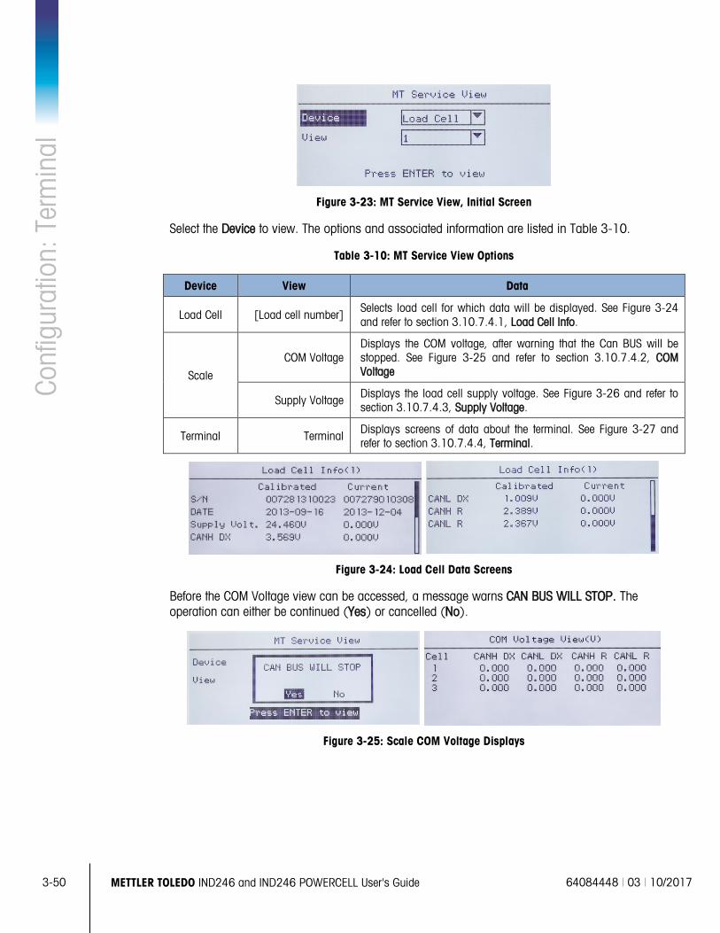
3-50
METTLER TOLEDO IND246 and IND246 POWERCELL User's Guide 64084448 | 03 | 10/2017
Conf
igur
atio
n: T
erm
inal
Figure 3-23: MT Service View, Initial Screen
Select the Device to view. The options and associated information are listed in Table 3-10.
Table 3-10: MT Service View Options
Device View Data
Load Cell [Load cell number] Selects load cell for which data will be displayed. See Figure 3-24 and refer to section 3.10.7.4.1, Load Cell Info.
Scale
COM Voltage Displays the COM voltage, after warning that the Can BUS will be stopped. See Figure 3-25 and refer to section 3.10.7.4.2, COM Voltage
Supply Voltage Displays the load cell supply voltage. See Figure 3-26 and refer to section 3.10.7.4.3, Supply Voltage.
Terminal Terminal Displays screens of data about the terminal. See Figure 3-27 and refer to section 3.10.7.4.4, Terminal.
Figure 3-24: Load Cell Data Screens
Before the COM Voltage view can be accessed, a message warns CAN BUS WILL STOP. The operation can either be continued (Yes) or cancelled (No).
Figure 3-25: Scale COM Voltage Displays
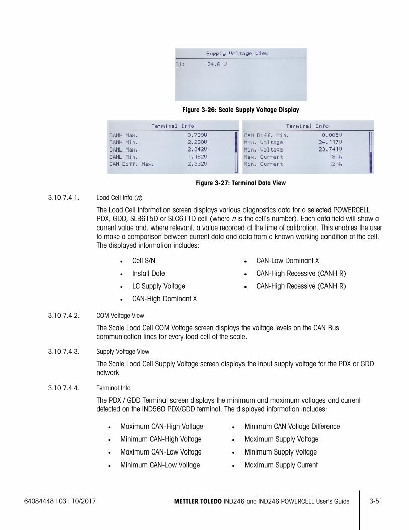
64084448 | 03 | 10/2017 METTLER TOLEDO IND246 and IND246 POWERCELL User's Guide
3-51
Figure 3-26: Scale Supply Voltage Display
Figure 3-27: Terminal Data View
3.10.7.4.1. Load Cell Info (n)
The Load Cell Information screen displays various diagnostics data for a selected POWERCELL PDX, GDD, SLB615D or SLC611D cell (where n is the cell’s number). Each data field will show a current value and, where relevant, a value recorded at the time of calibration. This enables the user to make a comparison between current data and data from a known working condition of the cell. The displayed information includes:
• Cell S/N • CAN-Low Dominant X
• Install Date • CAN-High Recessive (CANH R)
• LC Supply Voltage • CAN-High Recessive (CANH R)
• CAN-High Dominant X
3.10.7.4.2. COM Voltage View
The Scale Load Cell COM Voltage screen displays the voltage levels on the CAN Bus communication lines for every load cell of the scale.
3.10.7.4.3. Supply Voltage View
The Scale Load Cell Supply Voltage screen displays the input supply voltage for the PDX or GDD network.
3.10.7.4.4. Terminal Info
The PDX / GDD Terminal screen displays the minimum and maximum voltages and current detected on the IND560 PDX/GDD terminal. The displayed information includes:
• Maximum CAN-High Voltage • Minimum CAN Voltage Difference
• Minimum CAN-High Voltage • Maximum Supply Voltage
• Maximum CAN-Low Voltage • Minimum Supply Voltage
• Minimum CAN-Low Voltage • Maximum Supply Current
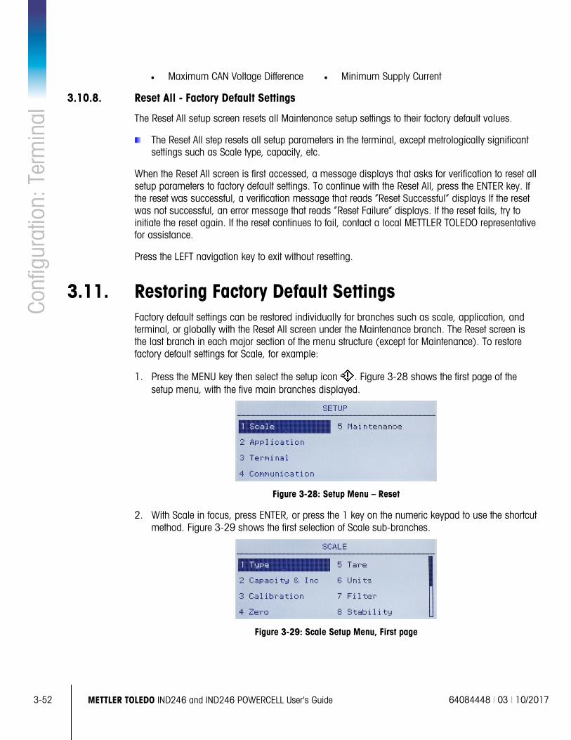
3-52
METTLER TOLEDO IND246 and IND246 POWERCELL User's Guide 64084448 | 03 | 10/2017
Conf
igur
atio
n: T
erm
inal
• Maximum CAN Voltage Difference • Minimum Supply Current
3.10.8. Reset All - Factory Default Settings
The Reset All setup screen resets all Maintenance setup settings to their factory default values.
The Reset All step resets all setup parameters in the terminal, except metrologically significant settings such as Scale type, capacity, etc.
When the Reset All screen is first accessed, a message displays that asks for verification to reset all setup parameters to factory default settings. To continue with the Reset All, press the ENTER key. If the reset was successful, a verification message that reads “Reset Successful” displays If the reset was not successful, an error message that reads “Reset Failure” displays. If the reset fails, try to initiate the reset again. If the reset continues to fail, contact a local METTLER TOLEDO representative for assistance.
Press the LEFT navigation key to exit without resetting.
3.11. Restoring Factory Default Settings Factory default settings can be restored individually for branches such as scale, application, and terminal, or globally with the Reset All screen under the Maintenance branch. The Reset screen is the last branch in each major section of the menu structure (except for Maintenance). To restore factory default settings for Scale, for example:
1. Press the MENU key then select the setup icon . Figure 3-28 shows the first page of the setup menu, with the five main branches displayed.
Figure 3-28: Setup Menu – Reset
2. With Scale in focus, press ENTER, or press the 1 key on the numeric keypad to use the shortcut method. Figure 3-29 shows the first selection of Scale sub-branches.
Figure 3-29: Scale Setup Menu, First page
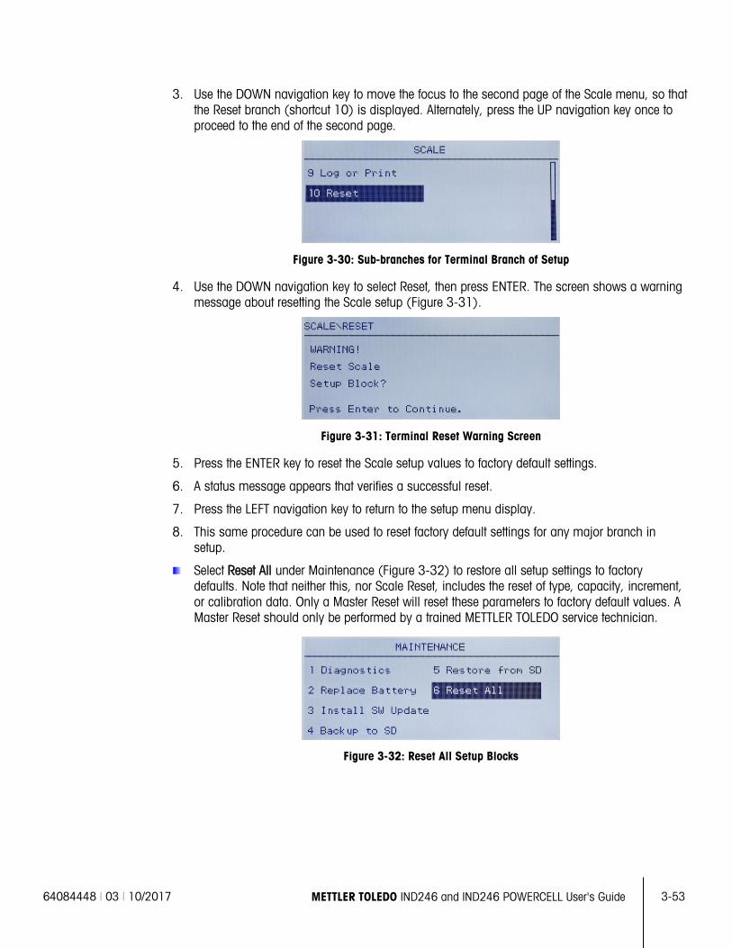
64084448 | 03 | 10/2017 METTLER TOLEDO IND246 and IND246 POWERCELL User's Guide
3-53
3. Use the DOWN navigation key to move the focus to the second page of the Scale menu, so that the Reset branch (shortcut 10) is displayed. Alternately, press the UP navigation key once to proceed to the end of the second page.
Figure 3-30: Sub-branches for Terminal Branch of Setup
4. Use the DOWN navigation key to select Reset, then press ENTER. The screen shows a warning message about resetting the Scale setup (Figure 3-31).
Figure 3-31: Terminal Reset Warning Screen
5. Press the ENTER key to reset the Scale setup values to factory default settings.
6. A status message appears that verifies a successful reset.
7. Press the LEFT navigation key to return to the setup menu display.
8. This same procedure can be used to reset factory default settings for any major branch in setup.
Select Reset All under Maintenance (Figure 3-32) to restore all setup settings to factory defaults. Note that neither this, nor Scale Reset, includes the reset of type, capacity, increment, or calibration data. Only a Master Reset will reset these parameters to factory default values. A Master Reset should only be performed by a trained METTLER TOLEDO service technician.
Figure 3-32: Reset All Setup Blocks
64084448 | 03 | 12/2017 METTLER TOLEDO IND246 and IND246 POWERCELL User's Guide
4-1
This chapter covers
• Animal Weighing
• Checkweighing
• Counting
• Peak Weight Measurement
• Vehicle Weighing
4 Applications: Configuration and Operation
4.1. Introduction Each of the following sections details operating procedures, operational features and function for the five applications included in the IND246 terminal.
For information on general operation of the IND246 terminal, please refer to Chapter 2, Operation: Terminal.
For information on general configuration of the IND246 terminal, please refer to Chapter 3, Configuration: Terminal.
4.2. Animal Weighing 4.2.1. Overview
The Animal Weighing application provides the ability to calculate and display an average weight value determined over a user-defined sampling period. This is useful when the weight is constantly unstable, as in the case of weighing live animals.
Two modes of operation are supported in the animal weighing application. One mode simply determines the average weight on the scale regardless if a single animal or multiple animals are on the scale. The second mode is designed for weighing multiple animals and provides the average weight per animal in addition to the total average weight of all animals. The application provides the following:
• Simple, one key operation
• Prompts for start of weighing cycle
• Weight averaged over variable sampling time period • Display of remaining time in cycle
• Final average weight display and print
When the FUNCTION key is pressed from the basic weigh mode the initial Animal Weighing display screen will be shown. The icon in the lower left corner indicates the Animal Weighing application mode. Pressing the FUNCTION key again will return the terminal to display the basic weighing mode.
4-2
METTLER TOLEDO IND246 and IND246 POWERCELL User's Guide 64084448 | 03 | 12/2017
Appl
icat
ions
4.2.2. Operational Features
In addition to the fundamental weighing functions, the following IND246 terminal basic weighing features can also be used within the Animal Weighing application.
4.2.2.1. ID Entry
An identification field (ID) is available for entry and printing. The ID will be retained until changed or cleared manually. ID entry can be completed in either of two ways – by pressing the ID key , entering data and then confirming the entry, or by entering data and then pressing the ID key .
4.2.2.1.1. ID Key First
Press the ID key at any time before or during a cycle to enter the identification field. An “ID?” prompt and data entry field will appear in the lower part of the display. Use the alphanumeric keypad to enter the ID information, then press ENTER to confirm and return to the operating mode.
4.2.2.1.2. Data First
At any time before or during a cycle, use the alphanumeric keypad to begin entry of the ID. A “Data:” prompt and data entry field will appear in the lower part of the display. Complete the entry then press the ID key to accept the ID and return to the operating mode.
4.2.2.2. Tare
A semi-automatic tare can be taken before the weighing cycle starts. Simply press the TARE key.
A preset tare value can be entered using the numeric keypad. Use the numeric keys to enter the preset tare value. The digits will appear in line 2 of the lower part of the display, below the “Data:” prompt. When tare entry is complete, press TARE to accept the value.
4.2.2.3. Discrete I/O
The animal weighing application supports one new discrete input and two new discrete outputs.
The new input is a command for Start that can be issued when the Press ENTER to Start message is displayed.
The two new outputs are Working and Cycle Complete. The Working output turns ON when the averaging cycle is in process and turns OFF after the average weight has been determined and is displayed. At this point, the Cycle Complete output turns ON. The Cycle Complete output turns OFF when the next averaging cycle is started.
4.2.2.4. Totalization
If Totalization is enabled, the averaged weight from the Animal Weighing application will also be added to the totals when printed.
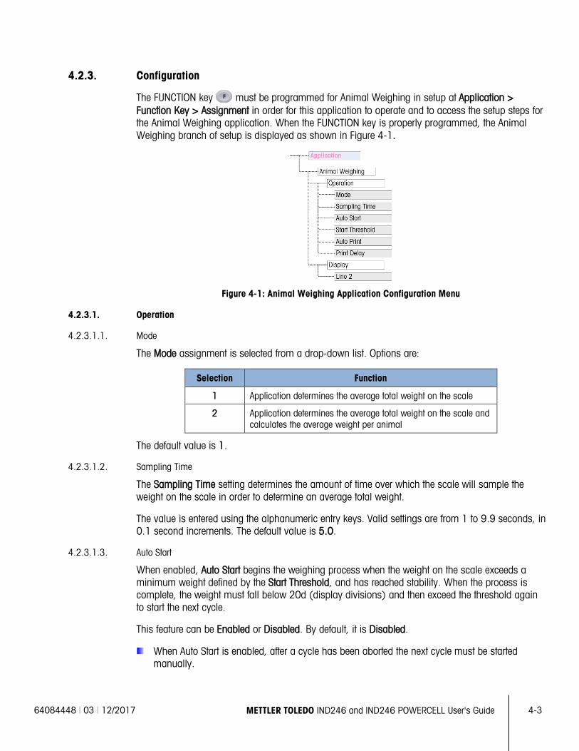
64084448 | 03 | 12/2017 METTLER TOLEDO IND246 and IND246 POWERCELL User's Guide
4-3
4.2.3. Configuration
The FUNCTION key must be programmed for Animal Weighing in setup at Application > Function Key > Assignment in order for this application to operate and to access the setup steps for the Animal Weighing application. When the FUNCTION key is properly programmed, the Animal Weighing branch of setup is displayed as shown in Figure 4-1.
Figure 4-1: Animal Weighing Application Configuration Menu
4.2.3.1. Operation
4.2.3.1.1. Mode
The Mode assignment is selected from a drop-down list. Options are:
Selection Function
1 Application determines the average total weight on the scale
2 Application determines the average total weight on the scale and calculates the average weight per animal
The default value is 1.
4.2.3.1.2. Sampling Time
The Sampling Time setting determines the amount of time over which the scale will sample the weight on the scale in order to determine an average total weight.
The value is entered using the alphanumeric entry keys. Valid settings are from 1 to 9.9 seconds, in 0.1 second increments. The default value is 5.0.
4.2.3.1.3. Auto Start
When enabled, Auto Start begins the weighing process when the weight on the scale exceeds a minimum weight defined by the Start Threshold, and has reached stability. When the process is complete, the weight must fall below 20d (display divisions) and then exceed the threshold again to start the next cycle.
This feature can be Enabled or Disabled. By default, it is Disabled.
When Auto Start is enabled, after a cycle has been aborted the next cycle must be started manually.
4-4
METTLER TOLEDO IND246 and IND246 POWERCELL User's Guide 64084448 | 03 | 12/2017
Appl
icat
ions
4.2.3.1.4. Start Threshold
The Start Threshold appears in the menu tree only when Auto Start is Enabled. It defines the scale weight value above which the averaging process will begin after stability is reached.
Valid settings are from 0 to the full scale capacity. This value should be relatively high – for example, 80% of the estimated weight of all animals on the scale. A very low number may cause the sampling period to start before all the animals are on the scale.
4.2.3.1.5. Auto Print
This Auto Print setting overrides the basic weighing Auto Print function, configured in setup at Scale > Log or Print > Automatic when operating within the application.
When Auto Print is enabled, the processed weight value is displayed for the amount of time defined by the Print Delay setting, and then a transaction print is automatically triggered.
This feature can be Enabled or Disabled. By default, it is Disabled.
4.2.3.1.6. Print Delay
Print Delay is only shown in the menu tree when Auto Print is enabled. It determines the delay between completion of the transaction and triggering the transaction print.
Valid settings are from 0 to 10 seconds in 1 second increments. The default value is 5.
4.2.3.2. Display
4.2.3.2.1. Line 2
The Line 2 assignment determines what data is displayed during and after a transaction. It is selected from a drop-down list. The selection list varies depending on the Mode selected:
Selection
Function
Mode 1 Mode 2
Disabled Line 2 is blank.
Average Not available Line 2 shows Average weight per animal
ID Line 2 shows the transaction ID Line 2 shows the transaction ID
The default value is Disabled.
4.2.4. Operating Sequence
The following sections describe the two modes of operation of the animal weighing application:
Mode 1 Determines the average total weight of a single animal or multiple animals
Mode 2 Determines the average total weight of multiple animals, and calculates the average weight per animal
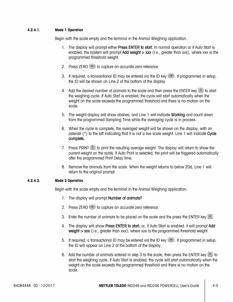
64084448 | 03 | 12/2017 METTLER TOLEDO IND246 and IND246 POWERCELL User's Guide
4-5
4.2.4.1. Mode 1 Operation
Begin with the scale empty and the terminal in the Animal Weighing application.
1. The display will prompt either Press ENTER to start. In normal operation or if Auto Start is enabled, the system will prompt Add weight > xxx (i.e., greater than xxx), where xxx is the programmed threshold weight.
2. Press ZERO to capture an accurate zero reference.
3. If required, a transactional ID may be entered via the ID key . If programmed in setup, the ID will be shown on Line 2 at the bottom of the display.
4. Add the desired number of animals to the scale and then press the ENTER key to start the weighing cycle. If Auto Start is enabled, the cycle will start automatically when the weight on the scale exceeds the programmed threshold and there is no-motion on the scale.
5. The weight display will show dashes, and Line 1 will indicate Working and count down from the programmed Sampling Time while the averaging cycle is in process.
6. When the cycle is complete, the averaged weight will be shown on the display, with an asterisk (*) to the left indicating that it is not a live scale weight. Line 1 will indicate Cycle complete.
7. Press PRINT to print the resulting average weight. The display will return to show the current weight on the scale. If Auto Print is selected, the print will be triggered automatically after the programmed Print Delay time.
8. Remove the animals from the scale. When the weight returns to below 20d, Line 1 will return to the original prompt.
4.2.4.2. Mode 2 Operation
Begin with the scale empty and the terminal in the Animal Weighing application.
1. The display will prompt Number of animals?
2. Press ZERO to capture an accurate zero reference.
3. Enter the number of animals to be placed on the scale and the press the ENTER key .
4. The display will show Press ENTER to start. or, if Auto Start is enabled, it will prompt Add weight > xxx (i.e., greater than xxx), where xxx is the programmed threshold weight.
5. If required, a transactional ID may be entered via the ID key . If programmed in setup, the ID will appear on Line 2 at the bottom of the display.
6. Add the number of animals entered in step 3 to the scale, then press the ENTER key to start the weighing cycle. If Auto Start is enabled, the cycle will start automatically when the weight on the scale exceeds the programmed threshold and there is no motion on the scale.
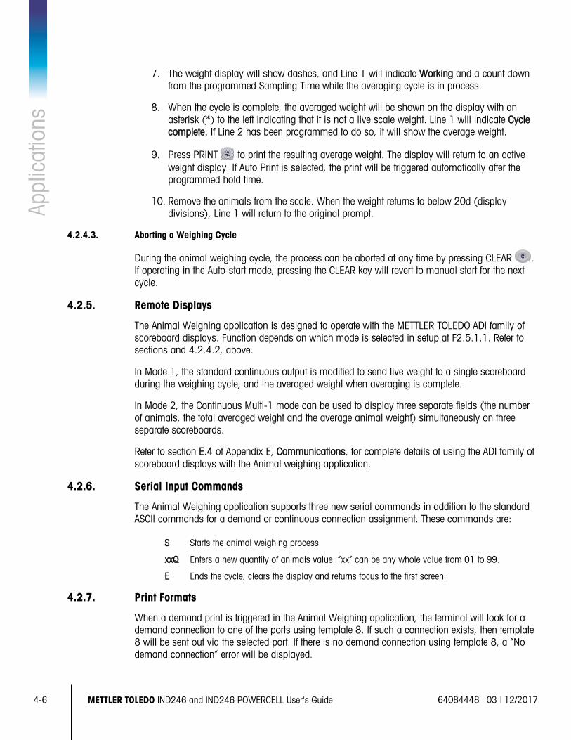
4-6
METTLER TOLEDO IND246 and IND246 POWERCELL User's Guide 64084448 | 03 | 12/2017
Appl
icat
ions
7. The weight display will show dashes, and Line 1 will indicate Working and a count down
from the programmed Sampling Time while the averaging cycle is in process.
8. When the cycle is complete, the averaged weight will be shown on the display with an asterisk (*) to the left indicating that it is not a live scale weight. Line 1 will indicate Cycle complete. If Line 2 has been programmed to do so, it will show the average weight.
9. Press PRINT to print the resulting average weight. The display will return to an active weight display. If Auto Print is selected, the print will be triggered automatically after the programmed hold time.
10. Remove the animals from the scale. When the weight returns to below 20d (display divisions), Line 1 will return to the original prompt.
4.2.4.3. Aborting a Weighing Cycle
During the animal weighing cycle, the process can be aborted at any time by pressing CLEAR . If operating in the Auto-start mode, pressing the CLEAR key will revert to manual start for the next cycle.
4.2.5. Remote Displays
The Animal Weighing application is designed to operate with the METTLER TOLEDO ADI family of scoreboard displays. Function depends on which mode is selected in setup at F2.5.1.1. Refer to sections and 4.2.4.2, above.
In Mode 1, the standard continuous output is modified to send live weight to a single scoreboard during the weighing cycle, and the averaged weight when averaging is complete.
In Mode 2, the Continuous Multi-1 mode can be used to display three separate fields (the number of animals, the total averaged weight and the average animal weight) simultaneously on three separate scoreboards.
Refer to section E.4 of Appendix E, Communications, for complete details of using the ADI family of scoreboard displays with the Animal weighing application.
4.2.6. Serial Input Commands
The Animal Weighing application supports three new serial commands in addition to the standard ASCII commands for a demand or continuous connection assignment. These commands are:
S Starts the animal weighing process.
xxQ Enters a new quantity of animals value. “xx” can be any whole value from 01 to 99.
E Ends the cycle, clears the display and returns focus to the first screen.
4.2.7. Print Formats
When a demand print is triggered in the Animal Weighing application, the terminal will look for a demand connection to one of the ports using template 8. If such a connection exists, then template 8 will be sent out via the selected port. If there is no demand connection using template 8, a “No demand connection” error will be displayed.
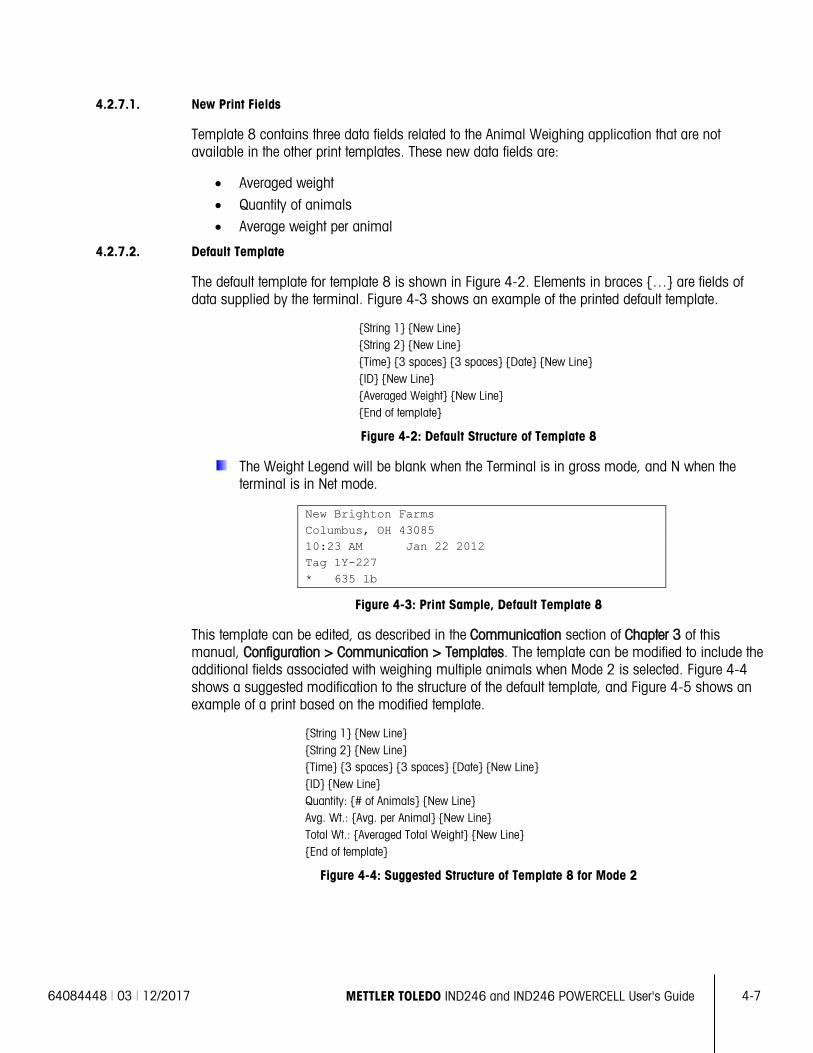
64084448 | 03 | 12/2017 METTLER TOLEDO IND246 and IND246 POWERCELL User's Guide
4-7
4.2.7.1. New Print Fields
Template 8 contains three data fields related to the Animal Weighing application that are not available in the other print templates. These new data fields are:
• Averaged weight
• Quantity of animals • Average weight per animal
4.2.7.2. Default Template
The default template for template 8 is shown in Figure 4-2. Elements in braces … are fields of data supplied by the terminal. Figure 4-3 shows an example of the printed default template.
String 1 New Line String 2 New Line Time 3 spaces 3 spaces Date New Line ID New Line Averaged Weight New Line End of template
Figure 4-2: Default Structure of Template 8
The Weight Legend will be blank when the Terminal is in gross mode, and N when the terminal is in Net mode.
New Brighton Farms Columbus, OH 43085 10:23 AM Jan 22 2012 Tag 1Y-227 * 635 lb
Figure 4-3: Print Sample, Default Template 8
This template can be edited, as described in the Communication section of Chapter 3 of this manual, Configuration > Communication > Templates. The template can be modified to include the additional fields associated with weighing multiple animals when Mode 2 is selected. Figure 4-4 shows a suggested modification to the structure of the default template, and Figure 4-5 shows an example of a print based on the modified template.
String 1 New Line String 2 New Line Time 3 spaces 3 spaces Date New Line ID New Line Quantity: # of Animals New Line Avg. Wt.: Avg. per Animal New Line Total Wt.: Averaged Total Weight New Line End of template
Figure 4-4: Suggested Structure of Template 8 for Mode 2
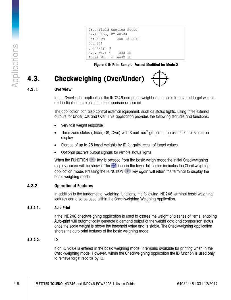
4-8
METTLER TOLEDO IND246 and IND246 POWERCELL User's Guide 64084448 | 03 | 12/2017
Appl
icat
ions
Greenfield Auction House Lexington, KY 40504 05:03 PM Jan 18 2012 Lot #21 Quantity: 8 Avg. Wt.: * 835 lb Total Wt.: * 6682 lb
Figure 4-5: Print Sample, Format Modified for Mode 2
4.3. Checkweighing (Over/Under) 4.3.1. Overview
In the Over/Under application, the IND246 compares weight on the scale to a stored target weight, and indicates the status of the comparison on screen.
The application can also control external equipment, such as status lights, using three external outputs for Under, OK and Over. This application provides the following features and functions:
• Very fast weight response
• Three zone status (Under, OK, Over) with SmartTrac® graphical representation of status on display
• Storage of up to 25 target weights by ID for quick recall of target values
• Optional discrete output signals for remote status lights
When the FUNCTION key is pressed from the basic weigh mode the initial Checkweighing display screen will be shown. The icon in the lower left corner indicates the Checkweighing application mode. Pressing the FUNCTION key again will return the terminal to display the basic weighing mode.
4.3.2. Operational Features
In addition to the fundamental weighing functions, the following IND246 terminal basic weighing features can also be used within the Checkweighing Weighing application.
4.3.2.1. Auto-Print
If the IND246 checkweighing application is used to assess the weight of a series of items, enabling Auto-print will automatically generate a demand output of the weight data and comparison status once the scale weight is above the threshold value and is stable. The Checkweighing application shares the auto print features of the basic weighing mode.
4.3.2.2. ID
If an ID value is entered in the basic weighing mode, it remains available for printing when in the Checkweighing mode. However, within the Checkweighing application the ID function is used only to retrieve target records by ID.
64084448 | 03 | 12/2017 METTLER TOLEDO IND246 and IND246 POWERCELL User's Guide
4-9
4.3.2.3. Tare
A semi-automatic tare can be taken any time during the weighing cycle. Simply press the TARE key.
A preset tare value can be entered using the numeric keypad. Use the numeric keys to enter the preset tare value. The digits will appear in line 2 of the lower part of the display, below the “Data:” prompt. When tare entry is complete, press TARE to accept the value.
4.3.2.4. Discrete I/O
The Checkweighing application supports three new discrete outputs.
The three new outputs are Under Zone, OK Zone and Over Zone:
• The Under Zone output turns ON when the weight on the scale is below the target minus the – tolerance value.
• The OK Zone status turns ON when the weight on the scale is above the target minus the – tolerance value and below the target plus the + tolerance value.
• The Over Zone output turns on when the weight on the scale exceeds the target plus the + tolerance value.
4.3.2.5. Target Table Import and Export
The METTLER TOLEDO IND246 File Transfer Tool (FTT) program, included on the IND246 Resource CD-ROM, runs on a PC to exchange application files and tables with the IND246 terminal. Refer to the User's Guide of the File Transfer Tool for details.
4.3.3. Configuration
The FUNCTION key must be programmed for Checkweighing in setup at Application > Function Key > Assignment in order for this application to operate and to access the setup steps for the Checkweighing application. When the FUNCTION key is properly programmed, the Checkweighing branch of setup is displayed as shown in Figure 4-6.
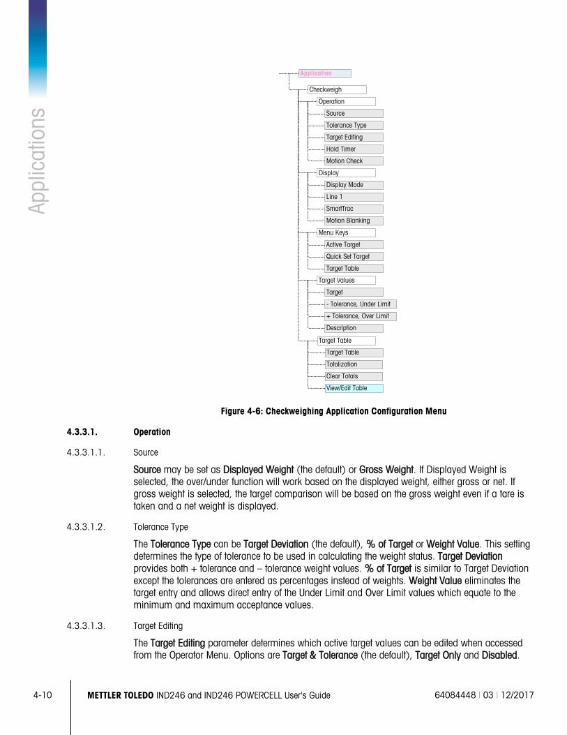
4-10
METTLER TOLEDO IND246 and IND246 POWERCELL User's Guide 64084448 | 03 | 12/2017
Appl
icat
ions
Figure 4-6: Checkweighing Application Configuration Menu
4.3.3.1. Operation
4.3.3.1.1. Source
Source may be set as Displayed Weight (the default) or Gross Weight. If Displayed Weight is selected, the over/under function will work based on the displayed weight, either gross or net. If gross weight is selected, the target comparison will be based on the gross weight even if a tare is taken and a net weight is displayed.
4.3.3.1.2. Tolerance Type
The Tolerance Type can be Target Deviation (the default), % of Target or Weight Value. This setting determines the type of tolerance to be used in calculating the weight status. Target Deviation provides both + tolerance and – tolerance weight values. % of Target is similar to Target Deviation except the tolerances are entered as percentages instead of weights. Weight Value eliminates the target entry and allows direct entry of the Under Limit and Over Limit values which equate to the minimum and maximum acceptance values.
4.3.3.1.3. Target Editing
The Target Editing parameter determines which active target values can be edited when accessed from the Operator Menu. Options are Target & Tolerance (the default), Target Only and Disabled.
Checkweigh
Operation
Source
Tolerance Type
Target Editing
Display Mode
Motion Blanking
Display
Quick Set Target
Menu Keys
Target Values
Active Target
Target Table
- Tolerance, Under Limit
Target
+ Tolerance, Over Limit
Hold Timer
Motion Check
SmartTrac
Line 1
Description
Application
Target Table
Totalization
Target Table
Clear Totals
View/Edit Table
64084448 | 03 | 12/2017 METTLER TOLEDO IND246 and IND246 POWERCELL User's Guide
4-11
Values are always editable from within setup, but only values selected as editable can be modified from the Operator Menu. Values not selected as editable can only be viewed.
The Description field can be edited if either Target Only or Target & Tolerance is selected.
If Target Editing is selected as Disabled, none of the values can be edited in the Operator Menu.
4.3.3.1.4. Hold Timer
The Hold Timer is a value, between 0.0 and 9.9 seconds, that sets the amount of time for which the display will freeze after a print command, before returning to the live display. If a second print command is issued during the set period, it will over-ride the existing count, the new current value will display, and the display will freeze again for the set time.
During the hold time, an asterisk (*) is shown on the display to indicate the weight is not live.
4.3.3.1.5. Motion Check
The Motion Check parameter can be Disabled (the default) or Enabled. When Enabled, the discrete outputs for Under, OK and Over and the zone indication on the display will turn ON only when no motion is detected. When Motion Check is Disabled, the corresponding output and zone indication display will turn on when the zone edge is reached, regardless of motion.
4.3.3.2. Display
4.3.3.2.1. Display Mode
This parameter determines what will be displayed in the main display area – Actual Weight (the default), Target Difference or No Display.
4.3.3.2.2. Line 1
Line 1 can be set to display the target Description (the default), ID, Target and Tolerances, Zone or Disabled (Line 1 blank).
4.3.3.2.3. SmartTrac
The graphic zone display of the results of the target comparison can be Enabled (the default) or Disabled.
If Line 1 is Disabled and SmartTrac is Enabled, the SmartTrac graphic will expand to occupy both lines of the lower display.
4.3.3.2.4. Motion Blanking
If Motion Blanking is Enabled, the numeric weight display will be blanked when the scale is in motion, and will only display a weight value when the scale is stable. Motion Blanking is Disabled by default.
4.3.3.3. Menu Keys
The Menu Keys parameters determine which functions will be accessible from the Operator Menu.
If the feature accessed by the key must be enabled or configured separately, such as the Target Table, enabling its menu key will display the corresponding icon in the Operator Menu, but will not give access to the feature.
4-12
METTLER TOLEDO IND246 and IND246 POWERCELL User's Guide 64084448 | 03 | 12/2017
Appl
icat
ions
4.3.3.3.1. Active Target
By default, the Active Target is Enabled, so that the active target and tolerance values in use can be viewed by the Operator. The Target Editing parameter at Operation > Target Editing determines which of the viewable fields can be edited.
4.3.3.3.2. Quick Set Target
Disabled by default, Quick Set Target can be Enabled to permit the Operator to define a new target by placing actual weights on the scale.
4.3.3.3.3. Target Table
Operator access to the Target Table can be Disabled (the default) or Enabled.
4.3.3.4. Target Values
Selecting Target Values opens a screen that displays the current target information. The appearance of this screen will vary depending on the Tolerance Type selected under Operation:
• If the Tolerance Type is set to Target Deviation or % of Target, the screen will include a target value together with upper and lower tolerances, expressed either as a weight value or a percentage of the target, and the Description field.
• If the Tolerance Type is Weight Value, the Under Limit and Over Limit are displayed, together with the Description field.
Each value is updated when focus leaves the entry box.
Note: Disabling all of the target menu keys will prohibit an operator from viewing or changing the target and tolerance values. These values can still be entered and edited in setup at the Target Values page.
4.3.3.5. Target Table
The Target Table can store up to 25 target IDs, each with its own target and tolerance values together with a description and (if Totalization is enabled) a total register and transaction counter. The target ID can be used for the quick recall of a set of target parameters for Checkweighing.
Note: The first 10 records are stored in memory on the main board and are always available. An SD memory card must be installed to store the remaining 15 records, giving a total of 25.
4.3.3.5.1. Target Table
The Target Table can be Enabled or Disabled (the default). If the table is Enabled, the Totalization and Clear Totals parameters and the View Table option also appear on the screen. If the table is Disabled, the ID field in Checkweighing will refer to the basic weighing ID.
4.3.3.5.2. Totalization
Totalization allows the terminal to track the total weight and number of transactions associated with an ID in the target table.
Totalization can be Enabled or Disabled (the default). If it is Enabled, count and total weight values are accumulated for each ID when a demand output with template 6 is generated.
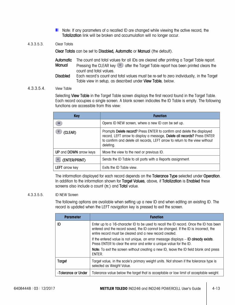
64084448 | 03 | 12/2017 METTLER TOLEDO IND246 and IND246 POWERCELL User's Guide
4-13
Note: If any parameters of a recalled ID are changed while viewing the active record, the Totalization link will be broken and accumulation will no longer occur.
4.3.3.5.3. Clear Totals
Clear Totals can be set to Disabled, Automatic or Manual (the default).
Automatic The count and total values for all IDs are cleared after printing a Target Table report. Manual Pressing the CLEAR key after the Target Table report has been printed clears the
count and total values. Disabled Each record’s count and total values must be re-set to zero individually, in the Target
Table view in setup, as described under View Table, below.
4.3.3.5.4. View Table
Selecting View Table in the Target Table screen displays the first record found in the Target Table. Each record occupies a single screen. A blank screen indicates the ID Table is empty. The following functions are accessible from this view:
Key Function
Opens ID NEW screen, where a new ID can be set up.
(CLEAR) Prompts Delete record? Press ENTER to confirm and delete the displayed record, LEFT arrow to display a message, Delete all records? Press ENTER to confirm and delete all records, LEFT arrow to return to the view without deleting.
UP and DOWN arrow keys Move the view to the next or previous ID.
(ENTER/PRINT) Sends the ID Table to all ports with a Reports assignment.
LEFT arrow key Exits the ID Table view.
The information displayed for each record depends on the Tolerance Type selected under Operation. In addition to the information shown for Target Values, above, if Totalization is Enabled these screens also include a count (n:) and Total value.
4.3.3.5.5. ID NEW Screen
The following options are available when setting up a new ID and when editing an existing ID. The record is updated when the LEFT navigation key is pressed to exit the screen.
Parameter Function
ID Enter up to a 16-character ID to be used to recall the ID record. Once the ID has been entered and the record saved, the ID cannot be changed. If the ID is incorrect, the entire record must be cleared and a new record created.
If the entered value is not unique, an error message displays – ID already exists. Press ENTER to clear the error and enter a unique value for the ID.
Note: To exit the screen without creating a new ID, leave the ID field blank and press ENTER.
Target Target value, in the scale’s primary weight units. Not shown if the tolerance type is selected as Weight Value.
-Tolerance or Under Tolerance value below the target that is acceptable or low limit of acceptable weight.
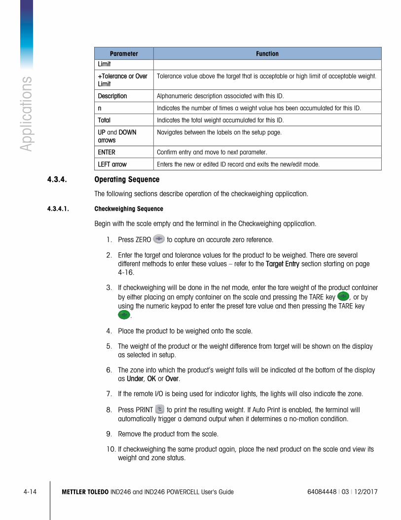
4-14
METTLER TOLEDO IND246 and IND246 POWERCELL User's Guide 64084448 | 03 | 12/2017
Appl
icat
ions
Parameter Function
Limit
+Tolerance or Over Limit
Tolerance value above the target that is acceptable or high limit of acceptable weight.
Description Alphanumeric description associated with this ID.
n Indicates the number of times a weight value has been accumulated for this ID.
Total Indicates the total weight accumulated for this ID.
UP and DOWN arrows
Navigates between the labels on the setup page.
ENTER Confirm entry and move to next parameter.
LEFT arrow Enters the new or edited ID record and exits the new/edit mode.
4.3.4. Operating Sequence
The following sections describe operation of the checkweighing application.
4.3.4.1. Checkweighing Sequence
Begin with the scale empty and the terminal in the Checkweighing application.
1. Press ZERO to capture an accurate zero reference.
2. Enter the target and tolerance values for the product to be weighed. There are several different methods to enter these values – refer to the Target Entry section starting on page 4-16.
3. If checkweighing will be done in the net mode, enter the tare weight of the product container by either placing an empty container on the scale and pressing the TARE key , or by using the numeric keypad to enter the preset tare value and then pressing the TARE key
.
4. Place the product to be weighed onto the scale.
5. The weight of the product or the weight difference from target will be shown on the display as selected in setup.
6. The zone into which the product’s weight falls will be indicated at the bottom of the display as Under, OK or Over.
7. If the remote I/O is being used for indicator lights, the lights will also indicate the zone.
8. Press PRINT to print the resulting weight. If Auto Print is enabled, the terminal will automatically trigger a demand output when it determines a no-motion condition.
9. Remove the product from the scale.
10. If checkweighing the same product again, place the next product on the scale and view its weight and zone status.
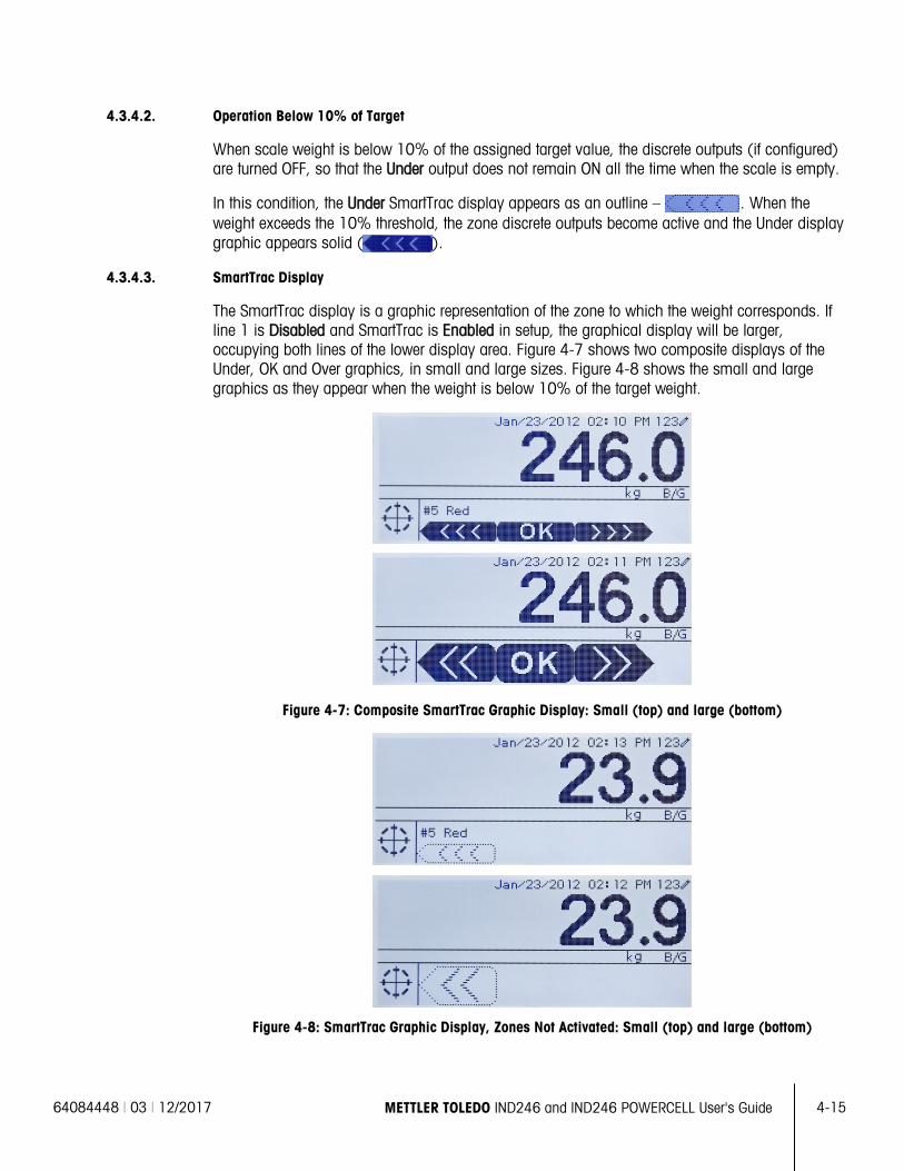
64084448 | 03 | 12/2017 METTLER TOLEDO IND246 and IND246 POWERCELL User's Guide
4-15
4.3.4.2. Operation Below 10% of Target
When scale weight is below 10% of the assigned target value, the discrete outputs (if configured) are turned OFF, so that the Under output does not remain ON all the time when the scale is empty.
In this condition, the Under SmartTrac display appears as an outline – . When the weight exceeds the 10% threshold, the zone discrete outputs become active and the Under display graphic appears solid ( ).
4.3.4.3. SmartTrac Display
The SmartTrac display is a graphic representation of the zone to which the weight corresponds. If line 1 is Disabled and SmartTrac is Enabled in setup, the graphical display will be larger, occupying both lines of the lower display area. Figure 4-7 shows two composite displays of the Under, OK and Over graphics, in small and large sizes. Figure 4-8 shows the small and large graphics as they appear when the weight is below 10% of the target weight.
Figure 4-7: Composite SmartTrac Graphic Display: Small (top) and large (bottom)
Figure 4-8: SmartTrac Graphic Display, Zones Not Activated: Small (top) and large (bottom)
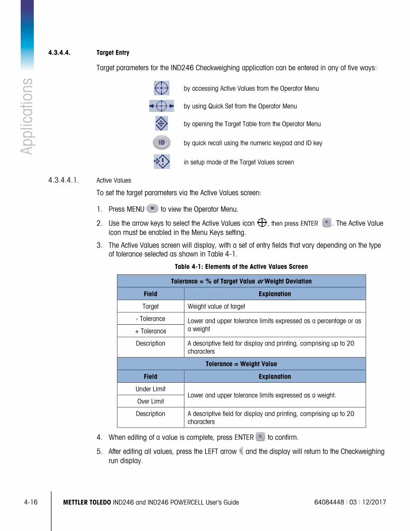
4-16
METTLER TOLEDO IND246 and IND246 POWERCELL User's Guide 64084448 | 03 | 12/2017
Appl
icat
ions
4.3.4.4. Target Entry
Target parameters for the IND246 Checkweighing application can be entered in any of five ways:
by accessing Active Values from the Operator Menu
by using Quick Set from the Operator Menu
by opening the Target Table from the Operator Menu
by quick recall using the numeric keypad and ID key
in setup mode at the Target Values screen
4.3.4.4.1. Active Values
To set the target parameters via the Active Values screen:
1. Press MENU to view the Operator Menu.
2. Use the arrow keys to select the Active Values icon , then press ENTER . The Active Value icon must be enabled in the Menu Keys setting.
3. The Active Values screen will display, with a set of entry fields that vary depending on the type of tolerance selected as shown in Table 4-1.
Table 4-1: Elements of the Active Values Screen
Tolerance = % of Target Value or Weight Deviation
Field Explanation
Target Weight value of target
- Tolerance Lower and upper tolerance limits expressed as a percentage or as a weight + Tolerance
Description A descriptive field for display and printing, comprising up to 20 characters
Tolerance = Weight Value
Field Explanation
Under Limit Lower and upper tolerance limits expressed as a weight.
Over Limit
Description A descriptive field for display and printing, comprising up to 20 characters
4. When editing of a value is complete, press ENTER to confirm.
5. After editing all values, press the LEFT arrow and the display will return to the Checkweighing run display.
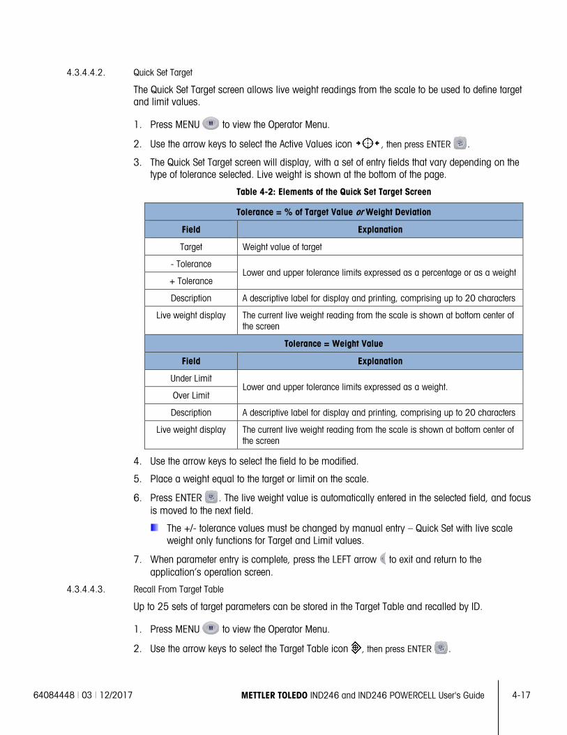
64084448 | 03 | 12/2017 METTLER TOLEDO IND246 and IND246 POWERCELL User's Guide
4-17
4.3.4.4.2. Quick Set Target
The Quick Set Target screen allows live weight readings from the scale to be used to define target and limit values.
1. Press MENU to view the Operator Menu.
2. Use the arrow keys to select the Active Values icon , then press ENTER .
3. The Quick Set Target screen will display, with a set of entry fields that vary depending on the type of tolerance selected. Live weight is shown at the bottom of the page.
Table 4-2: Elements of the Quick Set Target Screen
Tolerance = % of Target Value or Weight Deviation
Field Explanation
Target Weight value of target
- Tolerance Lower and upper tolerance limits expressed as a percentage or as a weight
+ Tolerance
Description A descriptive label for display and printing, comprising up to 20 characters
Live weight display The current live weight reading from the scale is shown at bottom center of the screen
Tolerance = Weight Value
Field Explanation
Under Limit Lower and upper tolerance limits expressed as a weight.
Over Limit
Description A descriptive label for display and printing, comprising up to 20 characters
Live weight display The current live weight reading from the scale is shown at bottom center of the screen
4. Use the arrow keys to select the field to be modified.
5. Place a weight equal to the target or limit on the scale.
6. Press ENTER . The live weight value is automatically entered in the selected field, and focus is moved to the next field.
The +/- tolerance values must be changed by manual entry – Quick Set with live scale weight only functions for Target and Limit values.
7. When parameter entry is complete, press the LEFT arrow to exit and return to the application’s operation screen.
4.3.4.4.3. Recall From Target Table
Up to 25 sets of target parameters can be stored in the Target Table and recalled by ID.
1. Press MENU to view the Operator Menu.
2. Use the arrow keys to select the Target Table icon , then press ENTER .
4-18
METTLER TOLEDO IND246 and IND246 POWERCELL User's Guide 64084448 | 03 | 12/2017
Appl
icat
ions
3. The first record from the Target Table will appear. The data in each record will vary depending
on the selected tolerance mode:
4. If Tolerance = % of Target Value or Weight Deviation, the fields are: ID, Description, Target, Units, -Tol, +Tol
5. If Tolerance = Weight Value, the fields are: ID, Description, Units, Under Limit, Over Limit.
6. Use the UP and DOWN arrows to move focus from one record to the next until the desired record is shown. Press ENTER to select it and return to the Checkweighing run display, or the LEFT arrow to return to the Operator Menu without selecting a new set of target parameters.
4.3.4.4.4. Quick Recall From Target Table
If the ID of the Target Table record is known, the record can be recalled without accessing the Operator Menu:
1. Use the keypad to begin to enter the alphanumeric ID number. The screen will show the Data: label on line 1, and the entered value on line 2 of the display.
2. When the entire ID has been entered, press ID to recall the record.
3. If the ID exists, the application will use the new parameters. If the ID is not found, an error message will appear – ID not found. Clear the message by pressing ENTER . The display will return to the checkweighing application, using the previous target parameters.
4.3.4.4.5. Setup Mode Target Entry
This entry mode is described in the Target Values configuration section, on page 4-12.
4.3.5. Print Formats
When a demand print is triggered in the Checkweighing application, the terminal will look for a demand connection to one of the ports using template 6. If such a connection exists, then template 6 will be sent out the selected port. If there is no demand connection using template 6, a “No demand connection” error will be displayed.
4.3.5.1. New Print Fields
Template 6 contains seven new data fields related to the Checkweighing application that are not available in the other templates. These new print fields are:
• n (count of totalization by ID)
• Target Description
• Target ID (from Target Table)
• Target Weight • Target and Tolerances
• Total (totalized weight by ID)
• Zone (text for the active zone – Under, OK, Over)
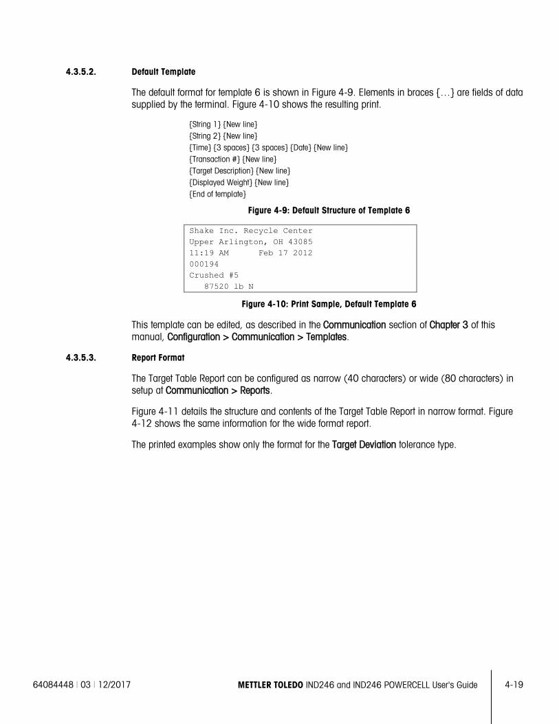
64084448 | 03 | 12/2017 METTLER TOLEDO IND246 and IND246 POWERCELL User's Guide
4-19
4.3.5.2. Default Template
The default format for template 6 is shown in Figure 4-9. Elements in braces … are fields of data supplied by the terminal. Figure 4-10 shows the resulting print.
String 1 New line String 2 New line Time 3 spaces 3 spaces Date New line Transaction # New line Target Description New line Displayed Weight New line End of template
Figure 4-9: Default Structure of Template 6
Shake Inc. Recycle Center Upper Arlington, OH 43085 11:19 AM Feb 17 2012 000194 Crushed #5 87520 lb N
Figure 4-10: Print Sample, Default Template 6
This template can be edited, as described in the Communication section of Chapter 3 of this manual, Configuration > Communication > Templates.
4.3.5.3. Report Format
The Target Table Report can be configured as narrow (40 characters) or wide (80 characters) in setup at Communication > Reports.
Figure 4-11 details the structure and contents of the Target Table Report in narrow format. Figure 4-12 shows the same information for the wide format report.
The printed examples show only the format for the Target Deviation tolerance type.
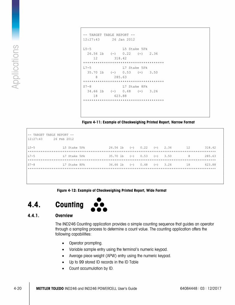
4-20
METTLER TOLEDO IND246 and IND246 POWERCELL User's Guide 64084448 | 03 | 12/2017
Appl
icat
ions
-- TARGET TABLE REPORT -- 12:27:43 26 Jan 2012 L5-5 L5 Stake 5Pk 26.56 lb (-) 0.22 (+) 2.36 12 318.42 *************************************** L7-5 L7 Stake 5Pk 35.70 lb (-) 0.53 (+) 3.50 8 285.63 *************************************** S7-8 L7 Stake 8Pk 34.66 lb (-) 0.48 (+) 3.26 18 623.88 ***************************************
Figure 4-11: Example of Checkweighing Printed Report, Narrow Format
-- TARGET TABLE REPORT -- 12:27:43 26 Feb 2012 L5-5 L5 Stake 5Pk 26.56 lb (-) 0.22 (+) 2.36 12 318.42 ****************************************************************************************************** L7-5 L7 Stake 5Pk 35.70 lb (-) 0.53 (+) 3.50 8 285.63 ****************************************************************************************************** S7-8 L7 Stake 8Pk 34.66 lb (-) 0.48 (+) 3.26 18 623.88 ******************************************************************************************************
Figure 4-12: Example of Checkweighing Printed Report, Wide Format
4.4. Counting 4.4.1. Overview
The IND246 Counting application provides a simple counting sequence that guides an operator through a sampling process to determine a count value. The counting application offers the following capabilities:
• Operator prompting.
• Variable sample entry using the terminal’s numeric keypad.
• Average piece weight (APW) entry using the numeric keypad.
• Up to 99 stored ID records in the ID Table • Count accumulation by ID.
64084448 | 03 | 12/2017 METTLER TOLEDO IND246 and IND246 POWERCELL User's Guide
4-21
When the FUNCTION key is pressed from the basic weigh mode the initial Counting display screen will be shown. The icon in the lower left corner indicates the Counting application mode. Pressing the FUNCTION key again will return the terminal to display the basic weighing mode.
4.4.2. Operational Features
In addition to the fundamental weighing functions, the following IND246 terminal basic weighing features can also be used within the Counting application.
4.4.2.1. Semi-Automatic Tare
When the Tare? prompt is displayed on the terminal, press TARE and the scale will tare to net zero. To take a new pushbutton tare when in counting mode and a number of pieces (PCS) is shown on the display, press the TARE key . The scale will tare to net zero, and the display will show 0 pieces.
4.4.2.2. Preset Tare
In the Sample – Tare sequence, when the Tare? prompt is displayed on the terminal, enter the preset tare value using the numeric keypad then press ENTER . If the terminal is already in counting mode, a preset tare can be entered by using the numeric keypad to enter the tare value, then press TARE .
4.4.2.3. ID
If an ID value is entered in the basic weighing mode, it remainsavailable for printing when in the Counting mode. However, within the Counting application, the ID function is used only to retrieve counting ID records.
4.4.2.4. Auto-Print
The IND246’s auto-printing feature is supported by the counting application. If the feature is enabled, a demand output will be sent automatically to the assigned output port when the weight settles to no-motion above the programmed threshold weight. This is a useful feature when counting the same part in the same weight carton repeatedly. By retaining the tare and APW values, a print can automatically be generated simply by removing the previous carton of parts and placing the next carton on the scale.
4.4.2.5. Target Table Import and Export
The METTLER TOLEDO IND246 File Transfer Tool (FTT) program, included on the IND246 Resource CD-ROM, runs on a PC to exchange application files and tables with the IND246 terminal. Refer to the User's Guide of the File Transfer Tool for details.
4.4.3. Configuration
The FUNCTION key must be programmed for Counting in setup at Application > Function Key > Assignment in order for this application to operate and to access the setup steps for the Counting application. When the FUNCTION key is properly programmed, the Counting branch of setup is displayed as shown in Figure 4-13.
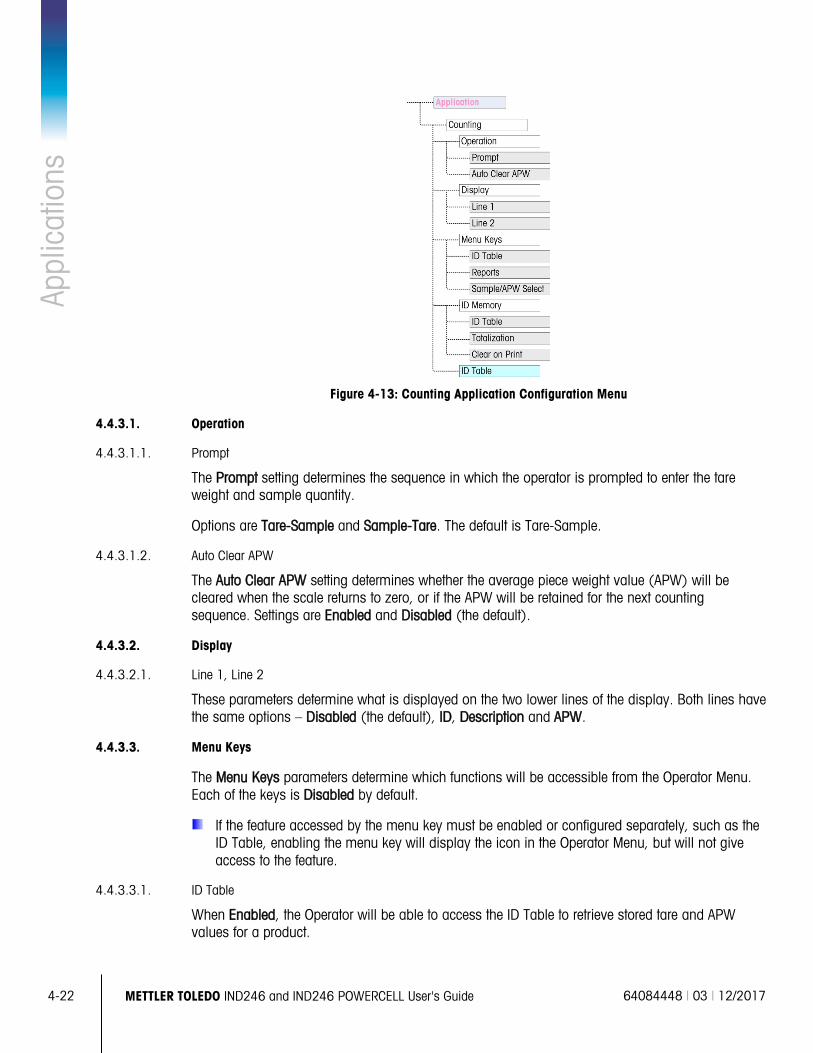
4-22
METTLER TOLEDO IND246 and IND246 POWERCELL User's Guide 64084448 | 03 | 12/2017
Appl
icat
ions
Figure 4-13: Counting Application Configuration Menu
4.4.3.1. Operation
4.4.3.1.1. Prompt
The Prompt setting determines the sequence in which the operator is prompted to enter the tare weight and sample quantity.
Options are Tare-Sample and Sample-Tare. The default is Tare-Sample.
4.4.3.1.2. Auto Clear APW
The Auto Clear APW setting determines whether the average piece weight value (APW) will be cleared when the scale returns to zero, or if the APW will be retained for the next counting sequence. Settings are Enabled and Disabled (the default).
4.4.3.2. Display
4.4.3.2.1. Line 1, Line 2
These parameters determine what is displayed on the two lower lines of the display. Both lines have the same options – Disabled (the default), ID, Description and APW.
4.4.3.3. Menu Keys
The Menu Keys parameters determine which functions will be accessible from the Operator Menu. Each of the keys is Disabled by default.
If the feature accessed by the menu key must be enabled or configured separately, such as the ID Table, enabling the menu key will display the icon in the Operator Menu, but will not give access to the feature.
4.4.3.3.1. ID Table
When Enabled, the Operator will be able to access the ID Table to retrieve stored tare and APW values for a product.
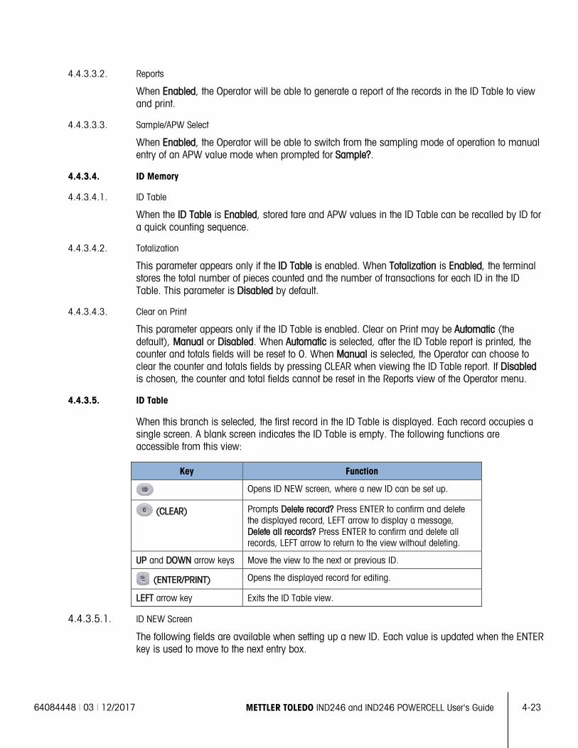
64084448 | 03 | 12/2017 METTLER TOLEDO IND246 and IND246 POWERCELL User's Guide
4-23
4.4.3.3.2. Reports
When Enabled, the Operator will be able to generate a report of the records in the ID Table to view and print.
4.4.3.3.3. Sample/APW Select
When Enabled, the Operator will be able to switch from the sampling mode of operation to manual entry of an APW value mode when prompted for Sample?.
4.4.3.4. ID Memory
4.4.3.4.1. ID Table
When the ID Table is Enabled, stored tare and APW values in the ID Table can be recalled by ID for a quick counting sequence.
4.4.3.4.2. Totalization
This parameter appears only if the ID Table is enabled. When Totalization is Enabled, the terminal stores the total number of pieces counted and the number of transactions for each ID in the ID Table. This parameter is Disabled by default.
4.4.3.4.3. Clear on Print
This parameter appears only if the ID Table is enabled. Clear on Print may be Automatic (the default), Manual or Disabled. When Automatic is selected, after the ID Table report is printed, the counter and totals fields will be reset to 0. When Manual is selected, the Operator can choose to clear the counter and totals fields by pressing CLEAR when viewing the ID Table report. If Disabled is chosen, the counter and total fields cannot be reset in the Reports view of the Operator menu.
4.4.3.5. ID Table
When this branch is selected, the first record in the ID Table is displayed. Each record occupies a single screen. A blank screen indicates the ID Table is empty. The following functions are accessible from this view:
Key Function
Opens ID NEW screen, where a new ID can be set up.
(CLEAR) Prompts Delete record? Press ENTER to confirm and delete the displayed record, LEFT arrow to display a message, Delete all records? Press ENTER to confirm and delete all records, LEFT arrow to return to the view without deleting.
UP and DOWN arrow keys Move the view to the next or previous ID.
(ENTER/PRINT) Opens the displayed record for editing.
LEFT arrow key Exits the ID Table view.
4.4.3.5.1. ID NEW Screen
The following fields are available when setting up a new ID. Each value is updated when the ENTER key is used to move to the next entry box.
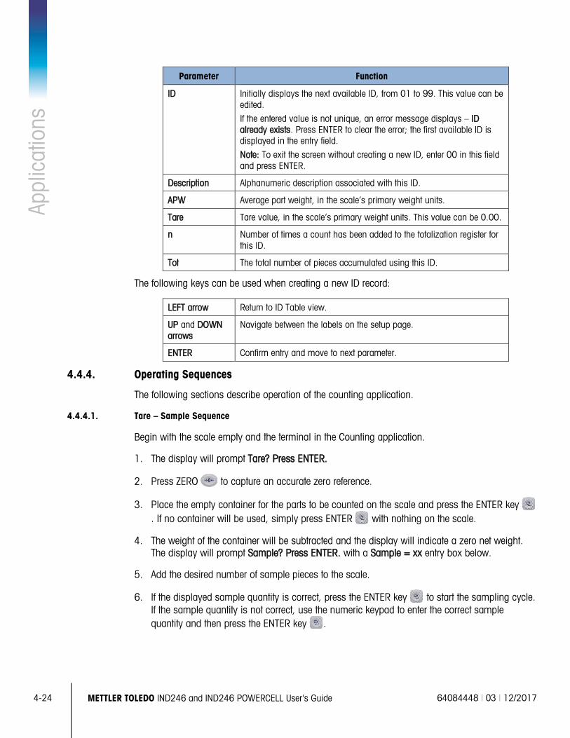
4-24
METTLER TOLEDO IND246 and IND246 POWERCELL User's Guide 64084448 | 03 | 12/2017
Appl
icat
ions
Parameter Function
ID Initially displays the next available ID, from 01 to 99. This value can be edited.
If the entered value is not unique, an error message displays – ID already exists. Press ENTER to clear the error; the first available ID is displayed in the entry field.
Note: To exit the screen without creating a new ID, enter 00 in this field and press ENTER.
Description Alphanumeric description associated with this ID.
APW Average part weight, in the scale’s primary weight units.
Tare Tare value, in the scale’s primary weight units. This value can be 0.00.
n Number of times a count has been added to the totalization register for this ID.
Tot The total number of pieces accumulated using this ID.
The following keys can be used when creating a new ID record:
LEFT arrow Return to ID Table view.
UP and DOWN arrows
Navigate between the labels on the setup page.
ENTER Confirm entry and move to next parameter.
4.4.4. Operating Sequences
The following sections describe operation of the counting application.
4.4.4.1. Tare – Sample Sequence
Begin with the scale empty and the terminal in the Counting application.
1. The display will prompt Tare? Press ENTER.
2. Press ZERO to capture an accurate zero reference.
3. Place the empty container for the parts to be counted on the scale and press the ENTER key . If no container will be used, simply press ENTER with nothing on the scale.
4. The weight of the container will be subtracted and the display will indicate a zero net weight. The display will prompt Sample? Press ENTER. with a Sample = xx entry box below.
5. Add the desired number of sample pieces to the scale.
6. If the displayed sample quantity is correct, press the ENTER key to start the sampling cycle. If the sample quantity is not correct, use the numeric keypad to enter the correct sample quantity and then press the ENTER key .
64084448 | 03 | 12/2017 METTLER TOLEDO IND246 and IND246 POWERCELL User's Guide
4-25
7. The main display will change from showing weight to showing the piece count. As additional pieces are added to the scale, the count will increment. Place all pieces to be counted onto the scale.
8. Press PRINT to print the resulting count. If Auto Print is enabled, the terminal will automatically trigger a demand output when it determines a no-motion condition.
9. Remove the container from the scale and the display will show a piece count equivalent to the tare weight.
10. If counting the same pieces again, place an empty container on the scale and press TARE to tare to net zero. Additional pieces added to the container will be shown.
4.4.4.2. Sample – Tare Sequence
Begin with the scale empty and the terminal in the Counting application.
1. The display will prompt Sample? Press ENTER. with a Sample = xx entry box below.
2. Press ZERO to capture an accurate zero reference.
3. Add the desired number of sample pieces to the scale.
4. If the displayed sample quantity is correct, press the ENTER key . If the sample quantity is not correct, use the numeric keypad to enter the correct sample quantity and then press the ENTER key .
5. The display will prompt Tare? Press ENTER. with an entry box below.
6. Enter the known preset tare value of the container using the numeric keypad and then press the ENTER key . If the tare weight of the container is not known, simply press ENTER and the tare will be entered later in the sequence.
7. The display will now show the piece count.
8. In the case that the container tare value was not know and was not entered as a preset tare in step 6 above, remove any sample pieces from the scale and place the empty container on the scale. Press the TARE key to tare the container. The display will now show zero pieces.
9. As additional pieces are added to the scale, the count will increment. Place all pieces to be counted onto the scale.
10. Press PRINT to print the resulting count. If Auto Print is enabled, the terminal will automatically trigger a demand output when it determines a no-motion condition.
11. Remove the container from the scale and the display will show a piece count equivalent to the tare weight.
12. If counting the same pieces again, place an empty container on the scale and press TARE to tare to net zero. Additional pieces added to the container will be shown.
4-26
METTLER TOLEDO IND246 and IND246 POWERCELL User's Guide 64084448 | 03 | 12/2017
Appl
icat
ions
4.4.4.3. Count Out Sequence
The IND246 Counting application can be used to count out pieces from a container placed on the scale. This function varies depending on the mode in use.
4.4.4.3.1. Tare-Sample
1. At the Tare? prompt, place the entire container on the scale and press ENTER .
2. At the Sample? prompt, remove the sample quantity from the container and press ENTER .
3. The terminal will display a negative count equal to the sample quantity. As additional pieces are removed the count will update in a negative direction.
4.4.4.3.2. APW
If in the Tare-Sample sequence and the display is prompting APW?:
1. Enter the APW of the part and press ENTER .
2. The terminal will display a count of zero pieces.
3. As pieces are removed the count will update in a negative direction.
4.4.4.3.3. Sample-Tare
1. Place the sample pieces on the empty scale and press ENTER .
2. At the Tare? prompt, place the full container on the scale and press ENTER .
3. The terminal will display a count of zero pieces.
4. As pieces are removed from the container, the count will update in a negative direction.
4.4.4.4. Counting a Full Container
Parts in a full container can be counted when the terminal is in Sample-Tare mode.
1. Take the sample as normal.
2. At the Tare? prompt, use the numeric keypad to enter the preset tare value of the container and press ENTER .
3. Place the full container on the scale. The count will update to show the total number of pieces.
4.4.4.5. Switching from Sample to APW Entry Mode
The normal sampling sequence requires taking a sample to determine the APW value for the part. If the APW is already known, it can be entered directly by changing the entry mode from sampling to APW entry.
The mode switching icon ( or ) must be enabled in setup (at Application > Counting > Menu Keys) in order to appear on the Operator Menu.
When the terminal’s display language is set to English, the icon will appear. If any other language is set, will appear.
64084448 | 03 | 12/2017 METTLER TOLEDO IND246 and IND246 POWERCELL User's Guide
4-27
To change the mode from Sampling to APW entry:
1. When the display is prompting Sample?, press the MENU key to access the Operator Menu.
2. Select Sample/APW key or and press ENTER .
3. The prompt will now show APW? and support direct entry of an APW.
To change the mode from APW entry to Sampling:
1. When the display is prompting APW?, press the MENU key to access the Operator Menu.
2. Select the Sample/APW key or and press ENTER .
3. The prompt will now show SAMPLE? and support part sampling to determine an APW.
4.4.4.6. Clearing the Counting Cycle
When the display is showing the number of pieces in a piece count, the display can be cleared back to the prompting sequence by pressing the CLEAR key twice. The first press of the CLEAR key will clear the tare value and the second press will clear the APW value and return the display to either the Tare? Or Sample? prompt, depending on the operating sequence selected.
4.4.4.7. Recall of Stored IDs
An ID Table can be enabled in setup to store up to 99 IDs. This is useful if the APW of the part being counted and the tare weight are consistent. Use of the stored values eliminates the taring and sampling process and shows the piece count immediately.
Each part ID is identified by a one- or two-digit ID number, and includes a description, tare weight, APW and (if so configured in setup) an accumulator and counter.
An ID Table record can be recalled by one of two methods:
• If the ID is not known, the record can be found by viewing the ID Table.
• If the ID is known, it can be entered in a Quick Recall sequence.
4.4.4.7.1. Recall from ID Table
To recall a record from the ID Table:
1. Press the MENU key to access the Operator Menu.
2. Select ID Table and press ENTER .
3. The first ID record will be displayed, with a scroll bar to the right.
4. Use the UP and DOWN navigation keys to move the view until the desired record is displayed:
a. Press ENTER to select the record and return to the counting application
b. Press the LEFT arrow to return to the counting application without selecting a record.
4-28
METTLER TOLEDO IND246 and IND246 POWERCELL User's Guide 64084448 | 03 | 12/2017
Appl
icat
ions
4.4.4.7.2. Quick ID Recall
When the display is in piece-counting mode, a known ID can be recalled directly:
1. Use the numeric keypad to enter the ID. A Data: label will display on line 1 of the display, and the entered number on line 2.
2. Once the ID has been entered, press ID to perform the recall.
3. If the ID is not found in the ID Table, an error message will appear. Clear the message by pressing ENTER . The display will return to the counting mode, using the previous APW value.
4.4.5. Print Formats
When a demand print is triggered in the Counting application, the terminal will look for a demand connection to one of the ports using template 9. If such a connection exists, then template 9 will be sent out via the selected port. If there is no demand connection using template 9, a “No demand connection” error will be displayed.
4.4.5.1. New Print Fields
Template 9 contains four new data fields related to the Counting application that are not available in the other templates. These new print fields are:
• APW • Piece Count
• Record ID (from ID Table)
• Record Description (from ID Table)
4.4.5.2. Default Template
The default structure for template 9 is shown in Figure 4-14. Elements in braces … are fields of data supplied by the terminal. Figure 4-15 shows a printed sample of the default template.
String 1 New line String 2 New line Time 3 spaces 3 spaces Date New line Displayed Weight New line Piece Count New line Record Description New line End of template
Figure 4-14: Default Structure of Template 9
Meyer’s Hardware Zurich, Switzerland 16:12:45 Feb 17 2012 12.20 lb N 450 PCS 4M x 12 Screw
Figure 4-15: Print Sample, Default Template 9
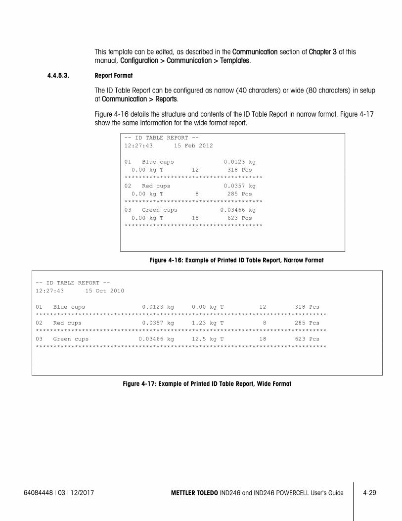
64084448 | 03 | 12/2017 METTLER TOLEDO IND246 and IND246 POWERCELL User's Guide
4-29
This template can be edited, as described in the Communication section of Chapter 3 of this manual, Configuration > Communication > Templates.
4.4.5.3. Report Format
The ID Table Report can be configured as narrow (40 characters) or wide (80 characters) in setup at Communication > Reports.
Figure 4-16 details the structure and contents of the ID Table Report in narrow format. Figure 4-17 show the same information for the wide format report.
-- ID TABLE REPORT -- 12:27:43 15 Feb 2012 01 Blue cups 0.0123 kg 0.00 kg T 12 318 Pcs *************************************** 02 Red cups 0.0357 kg 0.00 kg T 8 285 Pcs *************************************** 03 Green cups 0.03466 kg 0.00 kg T 18 623 Pcs ***************************************
Figure 4-16: Example of Printed ID Table Report, Narrow Format
-- ID TABLE REPORT -- 12:27:43 15 Oct 2010 01 Blue cups 0.0123 kg 0.00 kg T 12 318 Pcs ********************************************************************************** 02 Red cups 0.0357 kg 1.23 kg T 8 285 Pcs ********************************************************************************** 03 Green cups 0.03466 kg 12.5 kg T 18 623 Pcs **********************************************************************************
Figure 4-17: Example of Printed ID Table Report, Wide Format
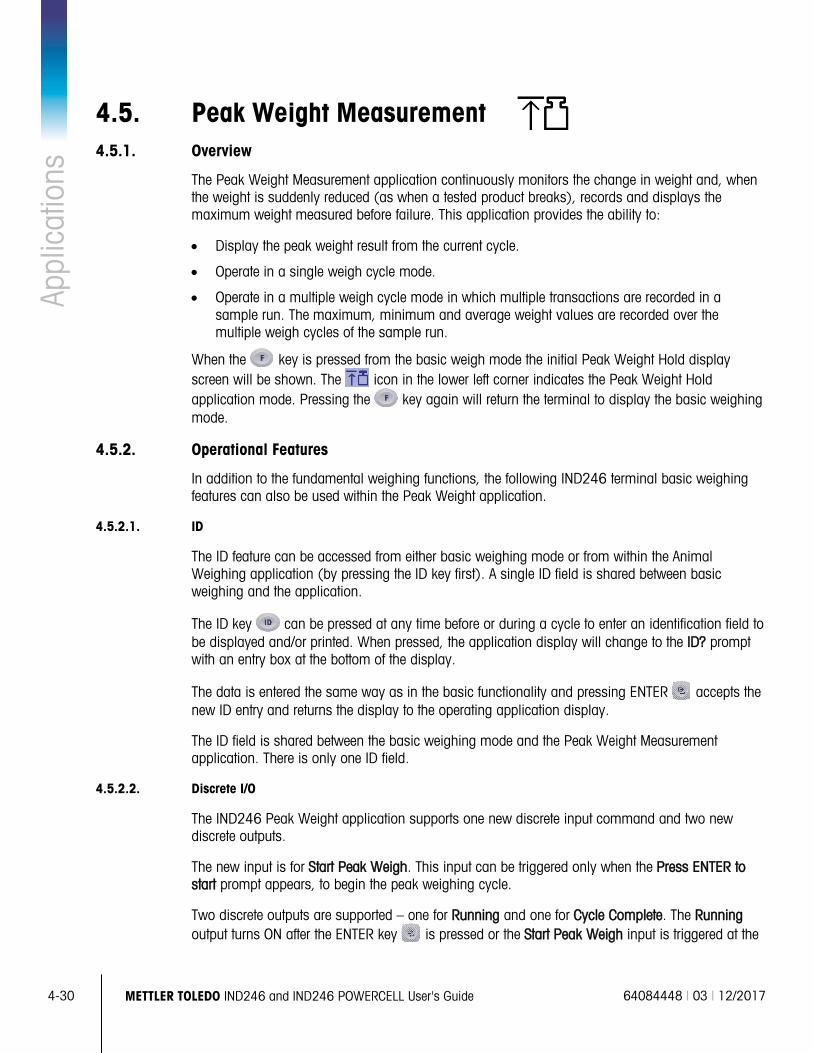
4-30
METTLER TOLEDO IND246 and IND246 POWERCELL User's Guide 64084448 | 03 | 12/2017
Appl
icat
ions
4.5. Peak Weight Measurement 4.5.1. Overview
The Peak Weight Measurement application continuously monitors the change in weight and, when the weight is suddenly reduced (as when a tested product breaks), records and displays the maximum weight measured before failure. This application provides the ability to:
• Display the peak weight result from the current cycle.
• Operate in a single weigh cycle mode.
• Operate in a multiple weigh cycle mode in which multiple transactions are recorded in a sample run. The maximum, minimum and average weight values are recorded over the multiple weigh cycles of the sample run.
When the key is pressed from the basic weigh mode the initial Peak Weight Hold display screen will be shown. The icon in the lower left corner indicates the Peak Weight Hold application mode. Pressing the key again will return the terminal to display the basic weighing mode.
4.5.2. Operational Features
In addition to the fundamental weighing functions, the following IND246 terminal basic weighing features can also be used within the Peak Weight application.
4.5.2.1. ID
The ID feature can be accessed from either basic weighing mode or from within the Animal Weighing application (by pressing the ID key first). A single ID field is shared between basic weighing and the application.
The ID key can be pressed at any time before or during a cycle to enter an identification field to be displayed and/or printed. When pressed, the application display will change to the ID? prompt with an entry box at the bottom of the display.
The data is entered the same way as in the basic functionality and pressing ENTER accepts the new ID entry and returns the display to the operating application display.
The ID field is shared between the basic weighing mode and the Peak Weight Measurement application. There is only one ID field.
4.5.2.2. Discrete I/O
The IND246 Peak Weight application supports one new discrete input command and two new discrete outputs.
The new input is for Start Peak Weigh. This input can be triggered only when the Press ENTER to start prompt appears, to begin the peak weighing cycle.
Two discrete outputs are supported – one for Running and one for Cycle Complete. The Running output turns ON after the ENTER key is pressed or the Start Peak Weigh input is triggered at the
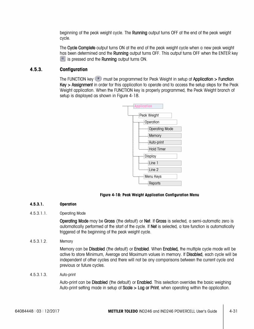
64084448 | 03 | 12/2017 METTLER TOLEDO IND246 and IND246 POWERCELL User's Guide
4-31
beginning of the peak weight cycle. The Running output turns OFF at the end of the peak weight cycle.
The Cycle Complete output turns ON at the end of the peak weight cycle when a new peak weight has been determined and the Running output turns OFF. This output turns OFF when the ENTER key
is pressed and the Running output turns ON.
4.5.3. Configuration
The FUNCTION key must be programmed for Peak Weight in setup at Application > Function Key > Assignment in order for this application to operate and to access the setup steps for the Peak Weight application. When the FUNCTION key is properly programmed, the Peak Weight branch of setup is displayed as shown in Figure 4-18.
Figure 4-18: Peak Weight Application Configuration Menu
4.5.3.1. Operation
4.5.3.1.1. Operating Mode
Operating Mode may be Gross (the default) or Net. If Gross is selected, a semi-automatic zero is automatically performed at the start of the cycle. If Net is selected, a tare function is automatically triggered at the beginning of the peak weight cycle.
4.5.3.1.2. Memory
Memory can be Disabled (the default) or Enabled. When Enabled, the multiple cycle mode will be active to store Minimum, Average and Maximum values in memory. If Disabled, each cycle will be independent of other cycles and there will not be any comparisons between the current cycle and previous or future cycles.
4.5.3.1.3. Auto-print
Auto-print can be Disabled (the default) or Enabled. This selection overrides the basic weighing Auto-print setting made in setup at Scale > Log or Print, when operating within the application.
Peak Weight
Operation
Operating Mode
Memory
Auto-print
Display
Menu Keys
Line 2
Line 1
Reports
Application
Hold Timer
4-32
METTLER TOLEDO IND246 and IND246 POWERCELL User's Guide 64084448 | 03 | 12/2017
Appl
icat
ions
4.5.3.1.4. Hold Timer
If Auto print is enabled, this parameter will be shown. The Hold Timer determines the number of seconds that the display will “freeze” at the end of the peak cycle before the automatic print is triggered. Values from 0.0 (no delay) to 9.9 are possible.
4.5.3.2. Display
4.5.3.2.1. Line 1
Line 1 of the lower display can be set to display Status (the default) or ID, or it can be Disabled.
4.5.3.2.2. Line 2
With memory disabled, Line 2 can be set to display Transaction # (the default), or it can be Disabled. With memory enabled. AVG, MAX or MIN values are added to the choices. If AVG, MAX or MIN is selected, the Cycle # will also display.
4.5.3.3. Menu Keys
The Menu Keys parameter determines whether the Peak Weight Reports icon will be accessible from the Operator Menu. By default, Operator access to Reports is Disabled.
The Reports icon provides access to the stored memory values MIN, AVG and MAX when operating in the memory mode.
4.5.4. Operating Sequences
Based on the desired operation, each peak weighment can be a separate transaction to determine the peak weight value of a sample or the peak values from several weighments can be recorded and the peak values from these transactions compared. The following two sequences are described in this section:
• Single Weigh Cycle (Memory disabled)
• Multiple Weigh Cycles (Memory enabled)
4.5.4.1. Single Weigh Cycle
The Single Weigh Cycle is the application’s simplest mode. In this mode each peak weight cycle is a separate transaction. No calculation is performed for averages or minimum/maximum values and only transactional prints are created – a printed report is not available.
Begin with the scale empty and the terminal in the Peak Weight application.
1. The display will prompt Press ENTER to start.
2. Install the sample to be tested into the test apparatus.
3. If required, a transactional ID may be entered by pressing the ID key then enter the ID data in the entry box below. Press ENTER when complete.
4. Press ENTER or trigger the Start Peak Weigh discrete input to begin the peak weigh cycle. The Cycle Complete discrete output turns OFF.
64084448 | 03 | 12/2017 METTLER TOLEDO IND246 and IND246 POWERCELL User's Guide
4-33
5. If gross mode operation was selected in setup, the terminal will perform a zero function to establish a valid zero reference point. If net mode operation was selected, the terminal will tare any weight on the scale to net zero as a reference point.
6. Line 1 under the weight display will indicate Running and the Running discrete output will turn ON. As pressure is applied to the sample, the terminal will monitor and display the resulting weight value.
7. Eventually, the sample will break due to the pressure and the weight will be reduced dramatically. The terminal will then display the heaviest weight measured before the sample broke. An asterisk (*) in the left of the display indicates the peak weight shown is not a live scale weight.
8. The status on Line 1 will change to Cycle complete. The Running discrete output will turn OFF and the Cycle Complete discrete output will turn ON.
9. Press PRINT to print the resulting weight. If Auto Print is enabled, the terminal will automatically trigger a demand output after the Hold Timer value is exceeded.
4.5.4.2. Multiple Weigh Cycles
Multiple Weigh Cycle mode is active when Memory is enabled in setup. In this mode, simple statistics are kept over several peak weighing cycles. While each peak weight cycle is still a separate transaction, calculations are done for the average peak weight, the minimum peak weight and maximum peak weight values over multiple cycles, and these statistics are kept in memory. When in the Multiple Weigh Cycle mode, the Peak Weigh process is repeated as many times as there are samples.
Refer to the Single Weight Cycle procedure above for step-by-step operation details.
The MAX, MIN or AVG statistic can be selected to appear in line 2 of the display. If enabled, the value from memory will be shown to the right of the cycle number. The statistics values in memory are updated at the end of each cycle, when the status changes to Cycle Complete.
The statistics from the multiple weighing cycles are available for viewing and printing in the Operator Menu (refer to Memory Operation, below).
4.5.4.3. Scale in Motion Error
The zero or tare function at the beginning of the Peak Weigh cycle cannot occur if the scale is not stable. When the Peak Weigh cycle is started, the terminal will wait the programmed amount of time (3, 10 or 30 seconds) for stability. If the scale stabilizes before the end of this timeout, the cycle will continue. If stability is not reached within this time:
• The cycle is aborted.
• A stability error message appears in the system line. • The Cycle Complete output will turn on again.
• The display will return to the Press ENTER to start. prompt, and the cycle must be restarted.
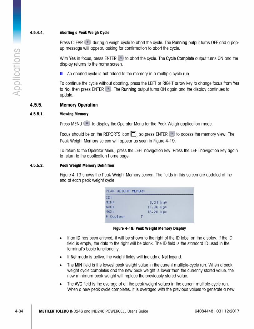
4-34
METTLER TOLEDO IND246 and IND246 POWERCELL User's Guide 64084448 | 03 | 12/2017
Appl
icat
ions
4.5.4.4. Aborting a Peak Weigh Cycle
Press CLEAR during a weigh cycle to abort the cycle. The Running output turns OFF and a pop-up message will appear, asking for confirmation to abort the cycle.
With Yes in focus, press ENTER to abort the cycle. The Cycle Complete output turns ON and the display returns to the home screen.
An aborted cycle is not added to the memory in a multiple cycle run.
To continue the cycle without aborting, press the LEFT or RIGHT arrow key to change focus from Yes to No, then press ENTER . The Running output turns ON again and the display continues to update.
4.5.5. Memory Operation
4.5.5.1. Viewing Memory
Press MENU to display the Operator Menu for the Peak Weigh application mode.
Focus should be on the REPORTS icon , so press ENTER to access the memory view. The Peak Weight Memory screen will appear as seen in Figure 4-19.
To return to the Operator Menu, press the LEFT navigation key. Press the LEFT navigation key again to return to the application home page.
4.5.5.2. Peak Weight Memory Definition
Figure 4-19 shows the Peak Weight Memory screen. The fields in this screen are updated at the end of each peak weight cycle.
Figure 4-19: Peak Weight Memory Display
• If an ID has been entered, it will be shown to the right of the ID label on the display. If the ID field is empty, the data to the right will be blank. The ID field is the standard ID used in the terminal’s basic functionality.
• If Net mode is active, the weight fields will include a Net legend.
• The MIN field is the lowest peak weight value in the current multiple-cycle run. When a peak weight cycle completes and the new peak weight is lower than the currently stored value, the new minimum peak weight will replace the previously stored value.
• The AVG field is the average of all the peak weight values in the current multiple-cycle run. When a new peak cycle completes, it is averaged with the previous values to generate a new
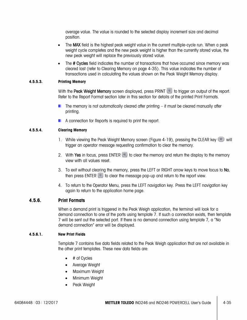
64084448 | 03 | 12/2017 METTLER TOLEDO IND246 and IND246 POWERCELL User's Guide
4-35
average value. The value is rounded to the selected display increment size and decimal position.
• The MAX field is the highest peak weight value in the current multiple-cycle run. When a peak weight cycle completes and the new peak weight is higher than the currently stored value, the new peak weight will replace the previously stored value.
• The # Cycles field indicates the number of transactions that have occurred since memory was cleared last (refer to Clearing Memory on page 4-35). This value indicates the number of transactions used in calculating the values shown on the Peak Weight Memory display.
4.5.5.3. Printing Memory
With the Peak Weight Memory screen displayed, press PRINT to trigger an output of the report. Refer to the Report Format section later in this section for details of the printed Print Formats.
The memory is not automatically cleared after printing – it must be cleared manually after printing.
A connection for Reports is required to print the report.
4.5.5.4. Clearing Memory
1. While viewing the Peak Weight Memory screen (Figure 4-19), pressing the CLEAR key will trigger an operator message requesting confirmation to clear the memory.
2. With Yes in focus, press ENTER to clear the memory and return the display to the memory view with all values reset.
3. To exit without clearing the memory, press the LEFT or RIGHT arrow keys to move focus to No, then press ENTER to clear the message pop-up and return to the report view.
4. To return to the Operator Menu, press the LEFT navigation key. Press the LEFT navigation key again to return to the application home page.
4.5.6. Print Formats
When a demand print is triggered in the Peak Weigh application, the terminal will look for a demand connection to one of the ports using template 7. If such a connection exists, then template 7 will be sent out the selected port. If there is no demand connection using template 7, a “No demand connection” error will be displayed.
4.5.6.1. New Print Fields
Template 7 contains five data fields related to the Peak Weigh application that are not available in the other print templates. These new data fields are:
• # of Cycles
• Average Weight
• Maximum Weight • Minimum Weight
• Peak Weight
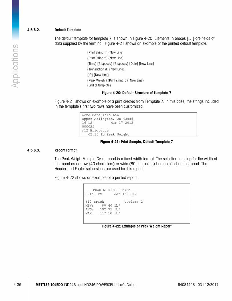
4-36
METTLER TOLEDO IND246 and IND246 POWERCELL User's Guide 64084448 | 03 | 12/2017
Appl
icat
ions
4.5.6.2. Default Template
The default template for template 7 is shown in Figure 4-20. Elements in braces … are fields of data supplied by the terminal. Figure 4-21 shows an example of the printed default template.
Print String 1 New Line
Print String 2 New Line
Time 3 spaces 3 spaces Date New Line
Transaction # New Line
ID New Line
Peak Weight Print string 5 New Line End of template
Figure 4-20: Default Structure of Template 7
Figure 4-21 shows an example of a print created from Template 7. In this case, the strings included in the template’s first two rows have been customized.
Acme Materials Lab Upper Arlington, OH 43085 16:12 Mar 17 2012 000025 #12 Briquette 62.15 lb Peak Weight
Figure 4-21: Print Sample, Default Template 7
4.5.6.3. Report Format
The Peak Weigh Multiple-Cycle report is a fixed-width format. The selection in setup for the width of the report as narrow (40 characters) or wide (80 characters) has no effect on the report. The Header and Footer setup steps are used for this report.
Figure 4-22 shows an example of a printed report.
-- PEAK WEIGHT REPORT -- 02:57 PM Jan 16 2012 #12 Brick Cycles: 2 MIN: 88.40 lb* AVG: 102.75 lb* MAX: 117.10 lb*
Figure 4-22: Example of Peak Weight Report
64084448 | 03 | 12/2017 METTLER TOLEDO IND246 and IND246 POWERCELL User's Guide
4-37
4.6. Vehicle Weighing An SD memory card must be installed in the terminal in order to run the Vehicle Weighing
application.
4.6.1. Overview
The IND246 Vehicle Weighing application provides two modes of operation to support Temporary Tare and Permanent Tare storing, retrieving and printing.
An icon at the lower left corner of the display indicates which of the two modes is active:
Temporary Tare Weighing
Permanent Tare Weighing
Either or both of these modes can be enabled in setup. If both modes are enabled, pressing FUNCTION once puts the terminal in Temporary Tare weighing mode and the temporary tare icon will be shown in the lower left corner of the display. A second press accesses Permanent Tare weighing and the Permanent Tare icon will be shown. After the last enabled mode is displayed, the next press of the FUNCTION key returns the terminal to the basic weighing mode.
The printing of vehicle weights without use of the storage/recall process is supported in the basic weighing mode. This is sometimes called Quick Print or Transient print, which simply prints gross vehicle weights.
4.6.1.1. Temporary Tare Weighing
Temporary Tare functionality is a two-pass mode that uses the Temporary ID table to store the weight from an inbound transaction. If required, the terminal can automatically assign a temporary two-digit ID. Alternatively, the ID can be assigned manually.
When the vehicle returns to the scale for the outbound transaction, the system recalls the previously stored weight associated with the vehicle’s ID, and the vehicle’s net weight calculated. Once the outbound ticket is printed, the Temporary Tare record is cleared from the table.
4.6.1.2. Permanent Tare Weighing
In this mode, the known tare weight for a vehicle is stored in the Permanent ID table, making one-pass weighing possible. When the full vehicle is on the weighing platform, the stored tare weight is recalled from memory by ID and an outbound process triggered.
New Permanent ID records can be created either by direct entry in setup or with an initial stored tare weight of zero. During the first transaction involving this vehicle, it will be weighed twice, once empty and once full, and the actual tare weight determined and updated to the record.
The Permanent ID table can be configured to accumulate total weights for trucks in a fleet of known vehicles.
4-38
METTLER TOLEDO IND246 and IND246 POWERCELL User's Guide 64084448 | 03 | 12/2017
Appl
icat
ions
4.6.2. Operational Features
In addition to the fundamental weighing functions, the following IND246 terminal basic weighing features can also be used within the Vehicle Weighing application.
4.6.2.1. ID Entry
If an ID value is entered in the basic weighing mode, it remains available for printing when in the Vehicle application. However, within the Vehicle application the ID function is used only to retrieve records from the Permanent ID table or the Temporary ID table.
4.6.2.2. Net Sign Correction
When enabled (in setup at Scale > Tare > Types), Net Sign Correction allows the IND246 to be used for both shipping (inbound empty) and receiving (inbound loaded) operations and always display a positive net weight. If net sign correction is disabled in setup, any stored weight value in the tare register is assumed to be a tare regardless of the gross weight present on the scale at the time of the final transaction. In this case, if the stored weight is actually the gross weight, the net value can be negative.
With net sign correction enabled, if the stored weight is larger than the weight on the scale, the terminal will treat the larger weight as the gross weight and the smaller weight as the tare weight, so that the difference will always result in a positive net weight.
4.6.2.3. Target Table Import and Export
The METTLER TOLEDO IND246 File Transfer Tool (FTT) program, included on the IND246 Resource CD-ROM, runs on a PC to exchange application files and tables with the IND246 terminal. Refer to the User's Guide of the File Transfer Tool for details.
4.6.3. Configuration
The FUNCTION key must be programmed for Vehicle Weighing in setup at Application > Function Key > Assignment in order for this application to operate and to access the setup steps for the Vehicle Weighing application. When the FUNCTION key is properly programmed, the Vehicle Weighing branch of setup is displayed as shown in Figure 4-23.
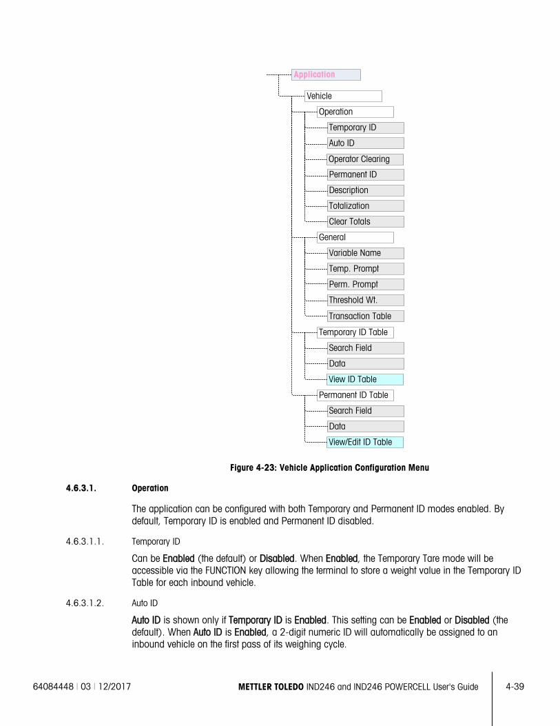
64084448 | 03 | 12/2017 METTLER TOLEDO IND246 and IND246 POWERCELL User's Guide
4-39
Figure 4-23: Vehicle Application Configuration Menu
4.6.3.1. Operation
The application can be configured with both Temporary and Permanent ID modes enabled. By default, Temporary ID is enabled and Permanent ID disabled.
4.6.3.1.1. Temporary ID
Can be Enabled (the default) or Disabled. When Enabled, the Temporary Tare mode will be accessible via the FUNCTION key allowing the terminal to store a weight value in the Temporary ID Table for each inbound vehicle.
4.6.3.1.2. Auto ID
Auto ID is shown only if Temporary ID is Enabled. This setting can be Enabled or Disabled (the default). When Auto ID is Enabled, a 2-digit numeric ID will automatically be assigned to an inbound vehicle on the first pass of its weighing cycle.
View ID Table
Vehicle
Operation
General
Permanent ID Table
Temporary ID
Auto ID
Permanent ID
Description
Totalization
Clear Totals
Variable Name
Temp. Prompt
Perm. Prompt
Threshold Wt.
Transaction Table
Temporary ID Table
Search Field
Data
View/Edit ID Table
Search Field
Data
Application
Operator Clearing
4-40
METTLER TOLEDO IND246 and IND246 POWERCELL User's Guide 64084448 | 03 | 12/2017
Appl
icat
ions
4.6.3.1.3. Operator Clearing
Operator Clearing is shown only if Temporary ID is Enabled. This setting can be Enabled or Disabled (the default). When Operator Clearing is Enabled, Temporary ID records can be cleared when viewed from the Operator Menu. If this step is Disabled, Temporary ID records can only be deleted from within setup.
4.6.3.1.4. Permanent ID
Can be Enabled or Disabled (the default). When Enabled, the Permanent Tare mode will be accessible via the FUNCTION key and the terminal will allow permanent tare values to be entered into the Permanent ID table.
4.6.3.1.5. Description
Description appears only if Permanent ID mode is Enabled, and can be Disabled (the default) or Enabled. When enabled, a Description entry field is available in setup for each Permanent ID record that can be printed in the outbound template.
4.6.3.1.6. Totalization
Totalization appears only if Permanent ID mode is Enabled, and can be Disabled (the default) or Enabled. If enabled, the net weight for each Permanent Tare outbound transaction will be added to the totals value for that Permanent ID.
4.6.3.1.7. Clear Totals
Clear Totals is available in Permanent ID mode only if Totalization is Enabled. It may be set to Automatic (the default), Manual or Disabled.
In Automatic mode, the count and total values are automatically cleared after printing a Permanent ID Table report. If Manual is selected, the CLEAR key can be pressed after printing the report to clear the count and total values. If Disabled is selected, the count and total values of each record have to be individually reset to zeroes while editing the records in the Permanent ID table view inside setup.
4.6.3.2. General
4.6.3.2.1. Variable Name
The Variable Name field allows entry of a 20 character prompt to be used on the display when prompting for entry of the variable data field. The same variable is used for both Temporary Tare and Permanent Tare operating modes. The default value is Var?.
4.6.3.2.2. Temp. Prompt
This step determines when in the Temporary Tare inbound/outbound sequence the variable should be prompted. It can be Disabled (the default), or set to Inbound or Outbound. If it is not Disabled, the Variable Name prompt is displayed either during the Inbound or Outbound pass of a Temporary Tare transaction, and the entered data is available for printing in the resulting ticket.
4.6.3.2.3. Perm. Prompt
This step determines if the variable prompt is shown in a Permanent Tare outbound sequence. It can be Disabled (the default), or set to Outbound. If it is set to Outbound, the Variable Name
64084448 | 03 | 12/2017 METTLER TOLEDO IND246 and IND246 POWERCELL User's Guide
4-41
prompt is displayed during the Permanent Tare transaction, and the entered data is available for printing in the resulting ticket.
4.6.3.2.4. Threshold Wt.
When the weight on the scale exceeds the Threshold Weight, the ID? prompt or Auto ID (if enabled) is automatically triggered. An inbound or outbound weighing process cannot start until the weight exceeds this value.
4.6.3.2.5. Transaction Table
The Transaction Table can be Disabled (the default) or Enabled. If Enabled, this table records information about each transaction up to 10,000 transactions. A pop-up message will warn that the table is nearly full after59,500 transactions have been recorded. At this point, only 500 more transactions can be recorded before a “Transaction table now full” message appears, and the table must be exported and cleared.
4.6.3.3. Temporary ID Table
Selecting the Temporary Tare ID table branch of the menu tree opens a TEMP ID SEARCH screen. Here, search parameters (field and data value) can be entered to narrow a search of the whole table. Once the parameters are set, move focus to Start and press ENTER to carry out the search and display the first Temporary ID record. Records are listed in the order in which the terminal stores them, and each will include ID, Weight, the entered Variable data (if enabled), Time and Date.
The UP and DOWN arrow keys scroll through the records, with one record displayed per screen. Only the CLEAR key functions in this screen.
4.6.3.3.1. Delete Record or All Records
To delete a currently displayed Temporary Tare ID record, press the CLEAR key . A prompt of Delete record? Will be shown with Yes in focus. To delete the record, press ENTER . To keep the record or to prompt for deletion of all records, change focus to No with the LEFT
or RIGHT arrow keys and press the ENTER key .
The display will prompt Delete all records? with a selection of Yes in focus. To delete all records, press ENTER . To keep all records, change the focus to NO with the LEFT or RIGHT arrow keys and press the ENTER key .
4.6.3.4. Permanent ID Table
Selecting the Permanent Tare ID table branch of the menu tree opens a PERM. ID SEARCH screen. Here, search parameters (field and data value) can be entered to narrow a search of the whole table. Once the parameters are set, move focus to Start and press ENTER to carry out the search and display the first Permanent Tare record. Records are shown in the order they were entered and, depending on which features are enabled, each will include ID, Description, Tare weight, the entered Variable data, and values for Count and Total.
The UP and DOWN arrow keys scroll through the records, with one record displayed per screen. The following keys are functional in this screen:
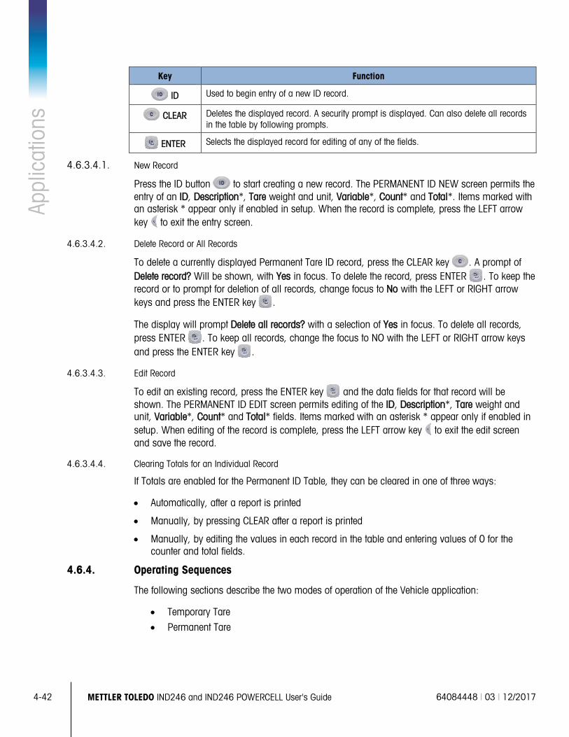
4-42
METTLER TOLEDO IND246 and IND246 POWERCELL User's Guide 64084448 | 03 | 12/2017
Appl
icat
ions
Key Function
ID Used to begin entry of a new ID record.
CLEAR Deletes the displayed record. A security prompt is displayed. Can also delete all records in the table by following prompts.
ENTER Selects the displayed record for editing of any of the fields.
4.6.3.4.1. New Record
Press the ID button to start creating a new record. The PERMANENT ID NEW screen permits the entry of an ID, Description*, Tare weight and unit, Variable*, Count* and Total*. Items marked with an asterisk * appear only if enabled in setup. When the record is complete, press the LEFT arrow key to exit the entry screen.
4.6.3.4.2. Delete Record or All Records
To delete a currently displayed Permanent Tare ID record, press the CLEAR key . A prompt of Delete record? Will be shown, with Yes in focus. To delete the record, press ENTER . To keep the record or to prompt for deletion of all records, change focus to No with the LEFT or RIGHT arrow keys and press the ENTER key .
The display will prompt Delete all records? with a selection of Yes in focus. To delete all records, press ENTER . To keep all records, change the focus to NO with the LEFT or RIGHT arrow keys and press the ENTER key .
4.6.3.4.3. Edit Record
To edit an existing record, press the ENTER key and the data fields for that record will be shown. The PERMANENT ID EDIT screen permits editing of the ID, Description*, Tare weight and unit, Variable*, Count* and Total* fields. Items marked with an asterisk * appear only if enabled in setup. When editing of the record is complete, press the LEFT arrow key to exit the edit screen and save the record.
4.6.3.4.4. Clearing Totals for an Individual Record
If Totals are enabled for the Permanent ID Table, they can be cleared in one of three ways:
• Automatically, after a report is printed
• Manually, by pressing CLEAR after a report is printed
• Manually, by editing the values in each record in the table and entering values of 0 for the counter and total fields.
4.6.4. Operating Sequences
The following sections describe the two modes of operation of the Vehicle application:
• Temporary Tare
• Permanent Tare
64084448 | 03 | 12/2017 METTLER TOLEDO IND246 and IND246 POWERCELL User's Guide
4-43
4.6.4.1. Temporary Tare Operation
Begin with the scale empty and the terminal in the Temporary Tare mode of the Vehicle Weighing application. The Temporary Tare icon will be shown in the lower left corner.
4.6.4.1.1. Inbound Transaction
1. The display will show Add weight > xxxx (i.e,. greater than xxxx) where xxxx is the threshold value entered in setup.
2. A vehicle pulls onto the scale and the weight exceeds the threshold value.
3. When a no-motion condition is detected, the display will change to the ID? prompt.
4. The alphanumeric identification (ID) for this record to be stored is entered in the entry box below the prompt. This ID will be used later to recall the stored weight. If Auto ID was enabled, a 2-digit ID will automatically be assigned by the terminal. This ID can be overwritten if desired. When the ID entry is complete, press the ENTER key .
5. If enabled in setup, the terminal will prompt for the variable entry. If so prompted, enter the variable transaction data using the alphanumeric keys and press ENTER when complete. The variable is a descriptive, printable field which is related to this specific vehicle or vehicle load.
6. The ID, weight and variable information for the inbound transaction is now displayed for confirmation. If the data is correct, press PRINT to generate the inbound transaction. If any of the data is not accurate, press the CLEAR key to clear all data and return to the ID? prompt.
7. The vehicle weight, variable (if entered), time and date are now stored in the Temporary ID Table (by the ID) and an inbound print is triggered. The Inbound transaction stays on screen for a duplicate print, if required.
Duplicate print capability is not available if the live weight on the scale deviates from the printed transaction weight by more than 50 divisions.
8. The display returns to its initial state after the duplicate ticket is printed, or when the weight changes more than 50 display divisions.
4.6.4.1.2. Outbound Transaction
1. The display will show Add weight > xxxx (i.e,. greater than xxxx) where xxxx is the threshold value entered in setup.
2. A vehicle which has already been weighed in an inbound transaction pulls onto the scale and the weight exceeds the threshold value.
3. When a no-motion condition is detected, the display will prompt ID?.
4. Enter the alphanumeric identification (ID) for this vehicle from the inbound transaction. If Auto ID is enabled, a 2-digit ID will automatically be assigned by the terminal. This ID must be overwritten with the ID from the inbound transaction. The ID can also be recalled by viewing the records in the Temporary ID Table and pressing ENTER when the desired record is displayed. When the ID entry is complete, press ENTER .
5. If the variable information was entered previously or if variable data is disabled, skip the next step.
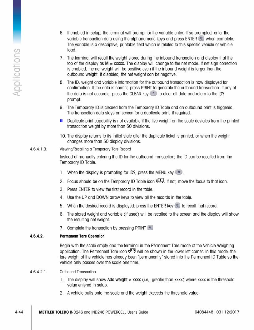
4-44
METTLER TOLEDO IND246 and IND246 POWERCELL User's Guide 64084448 | 03 | 12/2017
Appl
icat
ions
6. If enabled in setup, the terminal will prompt for the variable entry. If so prompted, enter the
variable transaction data using the alphanumeric keys and press ENTER when complete. The variable is a descriptive, printable field which is related to this specific vehicle or vehicle load.
7. The terminal will recall the weight stored during the inbound transaction and display it at the top of the display as M = xxxxx. The display will change to the net mode. If net sign correction is enabled, the net weight will be positive even if the inbound weight is larger than the outbound weight. If disabled, the net weight can be negative.
8. The ID, weight and variable information for the outbound transaction is now displayed for confirmation. If the data is correct, press PRINT to generate the outbound transaction. If any of the data is not accurate, press the CLEAR key to clear all data and return to the ID? prompt.
9. The Temporary ID is cleared from the Temporary ID Table and an outbound print is triggered. The transaction data stays on screen for a duplicate print, if required.
Duplicate print capability is not available if the live weight on the scale deviates from the printed transaction weight by more than 50 divisions.
10. The display returns to its initial state after the duplicate ticket is printed, or when the weight changes more than 50 display divisions.
4.6.4.1.3. Viewing/Recalling a Temporary Tare Record
Instead of manually entering the ID for the outbound transaction, the ID can be recalled from the Temporary ID Table.
1. When the display is prompting for ID?, press the MENU key .
2. Focus should be on the Temporary ID Table icon . If not, move the focus to that icon.
3. Press ENTER to view the first record in the table.
4. Use the UP and DOWN arrow keys to view all the records in the table.
5. When the desired record is displayed, press the ENTER key to recall that record.
6. The stored weight and variable (if used) will be recalled to the screen and the display will show the resulting net weight.
7. Complete the transaction by pressing PRINT .
4.6.4.2. Permanent Tare Operation
Begin with the scale empty and the terminal in the Permanent Tare mode of the Vehicle Weighing application. The Permanent Tare icon will be shown in the lower left corner. In this mode, the tare weight of the vehicle has already been “permanently” stored into the Permanent ID Table so the vehicle only passes over the scale one time.
4.6.4.2.1. Outbound Transaction
1. The display will show Add weight > xxxx (i.e,. greater than xxxx) where xxxx is the threshold value entered in setup.
2. A vehicle pulls onto the scale and the weight exceeds the threshold value.
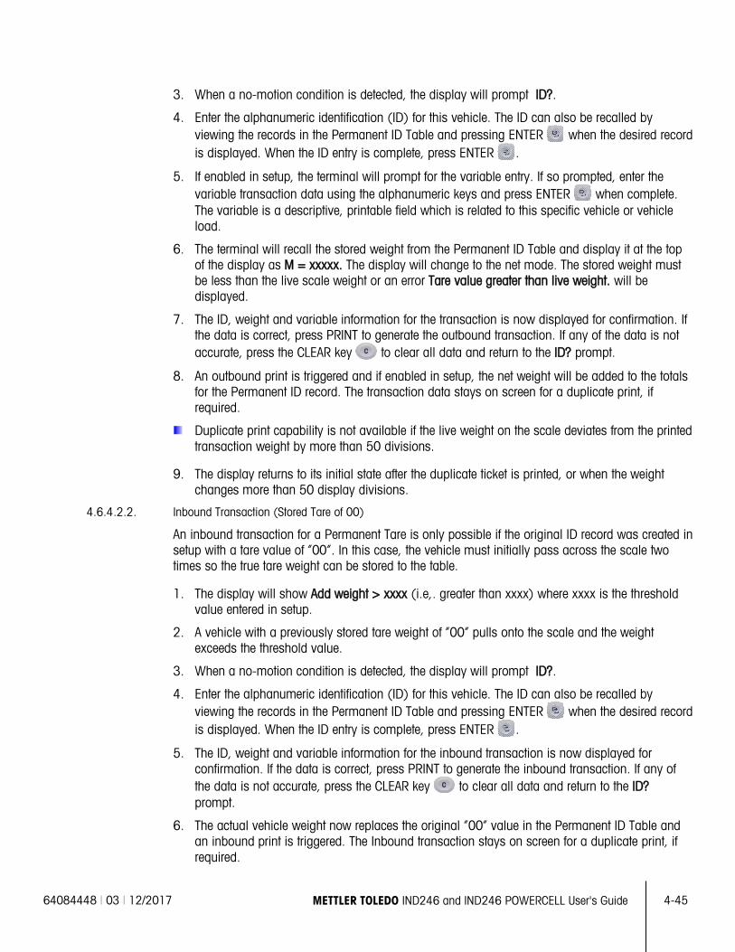
64084448 | 03 | 12/2017 METTLER TOLEDO IND246 and IND246 POWERCELL User's Guide
4-45
3. When a no-motion condition is detected, the display will prompt ID?.
4. Enter the alphanumeric identification (ID) for this vehicle. The ID can also be recalled by viewing the records in the Permanent ID Table and pressing ENTER when the desired record is displayed. When the ID entry is complete, press ENTER .
5. If enabled in setup, the terminal will prompt for the variable entry. If so prompted, enter the variable transaction data using the alphanumeric keys and press ENTER when complete. The variable is a descriptive, printable field which is related to this specific vehicle or vehicle load.
6. The terminal will recall the stored weight from the Permanent ID Table and display it at the top of the display as M = xxxxx. The display will change to the net mode. The stored weight must be less than the live scale weight or an error Tare value greater than live weight. will be displayed.
7. The ID, weight and variable information for the transaction is now displayed for confirmation. If the data is correct, press PRINT to generate the outbound transaction. If any of the data is not accurate, press the CLEAR key to clear all data and return to the ID? prompt.
8. An outbound print is triggered and if enabled in setup, the net weight will be added to the totals for the Permanent ID record. The transaction data stays on screen for a duplicate print, if required.
Duplicate print capability is not available if the live weight on the scale deviates from the printed transaction weight by more than 50 divisions.
9. The display returns to its initial state after the duplicate ticket is printed, or when the weight changes more than 50 display divisions.
4.6.4.2.2. Inbound Transaction (Stored Tare of 00)
An inbound transaction for a Permanent Tare is only possible if the original ID record was created in setup with a tare value of “00”. In this case, the vehicle must initially pass across the scale two times so the true tare weight can be stored to the table.
1. The display will show Add weight > xxxx (i.e,. greater than xxxx) where xxxx is the threshold value entered in setup.
2. A vehicle with a previously stored tare weight of “00” pulls onto the scale and the weight exceeds the threshold value.
3. When a no-motion condition is detected, the display will prompt ID?.
4. Enter the alphanumeric identification (ID) for this vehicle. The ID can also be recalled by viewing the records in the Permanent ID Table and pressing ENTER when the desired record is displayed. When the ID entry is complete, press ENTER .
5. The ID, weight and variable information for the inbound transaction is now displayed for confirmation. If the data is correct, press PRINT to generate the inbound transaction. If any of the data is not accurate, press the CLEAR key to clear all data and return to the ID? prompt.
6. The actual vehicle weight now replaces the original “00” value in the Permanent ID Table and an inbound print is triggered. The Inbound transaction stays on screen for a duplicate print, if required.
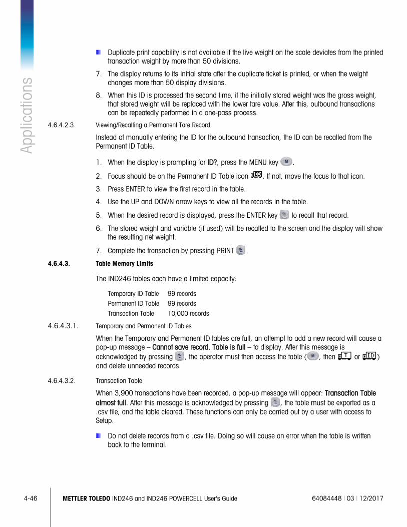
4-46
METTLER TOLEDO IND246 and IND246 POWERCELL User's Guide 64084448 | 03 | 12/2017
Appl
icat
ions
Duplicate print capability is not available if the live weight on the scale deviates from the printed
transaction weight by more than 50 divisions.
7. The display returns to its initial state after the duplicate ticket is printed, or when the weight changes more than 50 display divisions.
8. When this ID is processed the second time, if the initially stored weight was the gross weight, that stored weight will be replaced with the lower tare value. After this, outbound transactions can be repeatedly performed in a one-pass process.
4.6.4.2.3. Viewing/Recalling a Permanent Tare Record
Instead of manually entering the ID for the outbound transaction, the ID can be recalled from the Permanent ID Table.
1. When the display is prompting for ID?, press the MENU key .
2. Focus should be on the Permanent ID Table icon . If not, move the focus to that icon.
3. Press ENTER to view the first record in the table.
4. Use the UP and DOWN arrow keys to view all the records in the table.
5. When the desired record is displayed, press the ENTER key to recall that record.
6. The stored weight and variable (if used) will be recalled to the screen and the display will show the resulting net weight.
7. Complete the transaction by pressing PRINT .
4.6.4.3. Table Memory Limits
The IND246 tables each have a limited capacity:
Temporary ID Table 99 records
Permanent ID Table 99 records
Transaction Table 10,000 records
4.6.4.3.1. Temporary and Permanent ID Tables
When the Temporary and Permanent ID tables are full, an attempt to add a new record will cause a pop-up message – Cannot save record. Table is full – to display. After this message is acknowledged by pressing , the operator must then access the table ( , then or ) and delete unneeded records.
4.6.4.3.2. Transaction Table
When 3,900 transactions have been recorded, a pop-up message will appear: Transaction Table almost full. After this message is acknowledged by pressing , the table must be exported as a .csv file, and the table cleared. These functions can only be carried out by a user with access to Setup.
Do not delete records from a .csv file. Doing so will cause an error when the table is written back to the terminal.
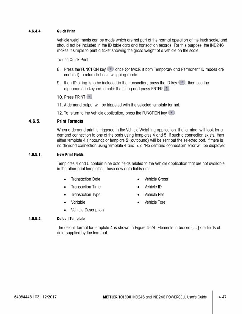
64084448 | 03 | 12/2017 METTLER TOLEDO IND246 and IND246 POWERCELL User's Guide
4-47
4.6.4.4. Quick Print
Vehicle weighments can be made which are not part of the normal operation of the truck scale, and should not be included in the ID table data and transaction records. For this purpose, the IND246 makes it simple to print a ticket showing the gross weight of a vehicle on the scale.
To use Quick Print:
8. Press the FUNCTION key once (or twice, if both Temporary and Permanent ID modes are enabled) to return to basic weighing mode.
9. If an ID string is to be included in the transaction, press the ID key , then use the alphanumeric keypad to enter the string and press ENTER .
10. Press PRINT .
11. A demand output will be triggered with the selected template format.
12. To return to the Vehicle application, press the FUNCTION key .
4.6.5. Print Formats
When a demand print is triggered in the Vehicle Weighing application, the terminal will look for a demand connection to one of the ports using templates 4 and 5. If such a connection exists, then either template 4 (inbound) or template 5 (outbound) will be sent out the selected port. If there is no demand connection using template 4 and 5, a “No demand connection” error will be displayed.
4.6.5.1. New Print Fields
Templates 4 and 5 contain nine data fields related to the Vehicle application that are not available in the other print templates. These new data fields are:
• Transaction Date • Vehicle Gross
• Transaction Time • Vehicle ID
• Transaction Type • Vehicle Net
• Variable • Vehicle Tare
• Vehicle Description
4.6.5.2. Default Template
The default format for template 4 is shown in Figure 4-24. Elements in braces … are fields of data supplied by the terminal.
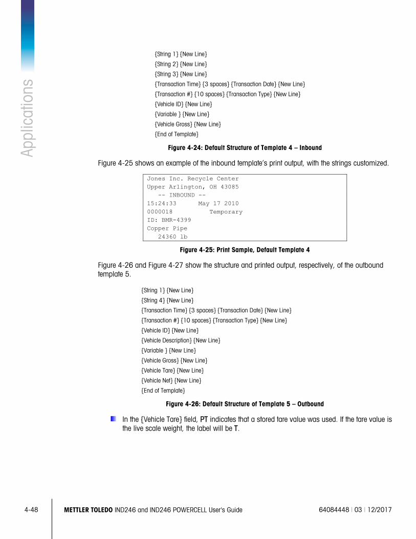
4-48
METTLER TOLEDO IND246 and IND246 POWERCELL User's Guide 64084448 | 03 | 12/2017
Appl
icat
ions
String 1 New Line
String 2 New Line
String 3 New Line
Transaction Time 3 spaces Transaction Date New Line
Transaction # 10 spaces Transaction Type New Line
Vehicle ID New Line
Variable New Line
Vehicle Gross New Line
End of Template
Figure 4-24: Default Structure of Template 4 – Inbound
Figure 4-25 shows an example of the inbound template’s print output, with the strings customized.
Jones Inc. Recycle Center Upper Arlington, OH 43085 -- INBOUND -- 15:24:33 May 17 2010 0000018 Temporary ID: BMR-4399 Copper Pipe 24360 lb
Figure 4-25: Print Sample, Default Template 4
Figure 4-26 and Figure 4-27 show the structure and printed output, respectively, of the outbound template 5.
String 1 New Line
String 4 New Line
Transaction Time 3 spaces Transaction Date New Line
Transaction # 10 spaces Transaction Type New Line
Vehicle ID New Line
Vehicle Description New Line
Variable New Line
Vehicle Gross New Line
Vehicle Tare New Line
Vehicle Net New Line
End of Template
Figure 4-26: Default Structure of Template 5 – Outbound
In the Vehicle Tare field, PT indicates that a stored tare value was used. If the tare value is the live scale weight, the label will be T.
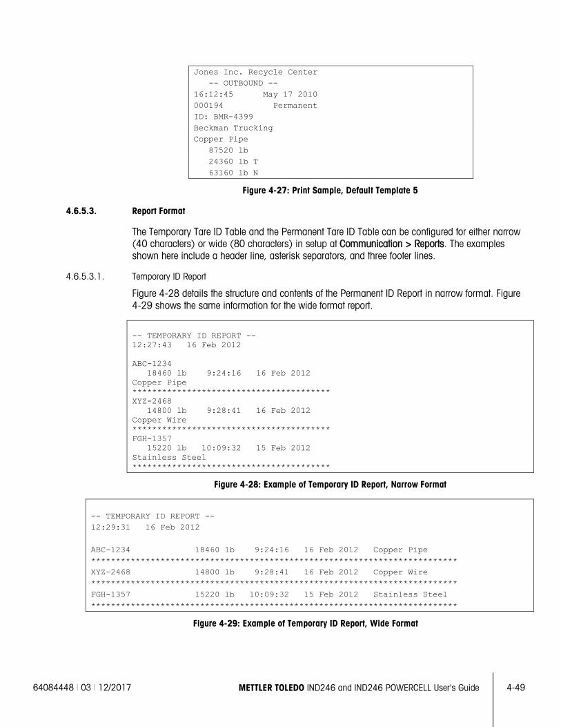
64084448 | 03 | 12/2017 METTLER TOLEDO IND246 and IND246 POWERCELL User's Guide
4-49
Jones Inc. Recycle Center -- OUTBOUND -- 16:12:45 May 17 2010 000194 Permanent ID: BMR-4399 Beckman Trucking Copper Pipe 87520 lb 24360 lb T 63160 lb N
Figure 4-27: Print Sample, Default Template 5
4.6.5.3. Report Format
The Temporary Tare ID Table and the Permanent Tare ID Table can be configured for either narrow (40 characters) or wide (80 characters) in setup at Communication > Reports. The examples shown here include a header line, asterisk separators, and three footer lines.
4.6.5.3.1. Temporary ID Report
Figure 4-28 details the structure and contents of the Permanent ID Report in narrow format. Figure 4-29 shows the same information for the wide format report.
-- TEMPORARY ID REPORT -- 12:27:43 16 Feb 2012 ABC-1234 18460 lb 9:24:16 16 Feb 2012 Copper Pipe **************************************** XYZ-2468 14800 lb 9:28:41 16 Feb 2012 Copper Wire **************************************** FGH-1357 15220 lb 10:09:32 15 Feb 2012 Stainless Steel ****************************************
Figure 4-28: Example of Temporary ID Report, Narrow Format
-- TEMPORARY ID REPORT -- 12:29:31 16 Feb 2012 ABC-1234 18460 lb 9:24:16 16 Feb 2012 Copper Pipe ************************************************************************** XYZ-2468 14800 lb 9:28:41 16 Feb 2012 Copper Wire ************************************************************************** FGH-1357 15220 lb 10:09:32 15 Feb 2012 Stainless Steel **************************************************************************
Figure 4-29: Example of Temporary ID Report, Wide Format
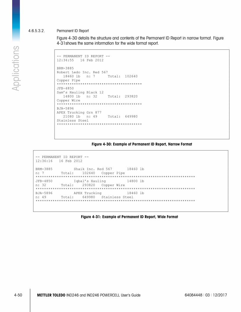
4-50
METTLER TOLEDO IND246 and IND246 POWERCELL User's Guide 64084448 | 03 | 12/2017
Appl
icat
ions
4.6.5.3.2. Permanent ID Report
Figure 4-30 details the structure and contents of the Permanent ID Report in narrow format. Figure 4-31shows the same information for the wide format report.
-- PERMANENT ID REPORT -- 12:34:55 16 Feb 2012 BRM-3885 Robert Ledo Inc. Red 567 18460 lb n: 7 Total: 102640 Copper Pipe **************************************** JFB-4850 Sam’s Hauling Black 12 14800 lb n: 32 Total: 293820 Copper Wire **************************************** BJA-5896 APEX Trucking Grn 877 21080 lb n: 49 Total: 649980 Stainless Steel ****************************************
Figure 4-30: Example of Permanent ID Report, Narrow Format
-- PERMANENT ID REPORT -- 12:36:16 16 Feb 2012 BRM-3885 Shaik Inc. Red 567 18460 lb n: 7 Total: 102640 Copper Pipe *************************************************************************** JFB-4850 Iqbal’s Hauling 14800 lb n: 32 Total: 293820 Copper Wire *************************************************************************** BJA-5896 APEX Trucking 18460 lb n: 49 Total: 649980 Stainless Steel ***************************************************************************
Figure 4-31: Example of Permanent ID Report, Wide Format
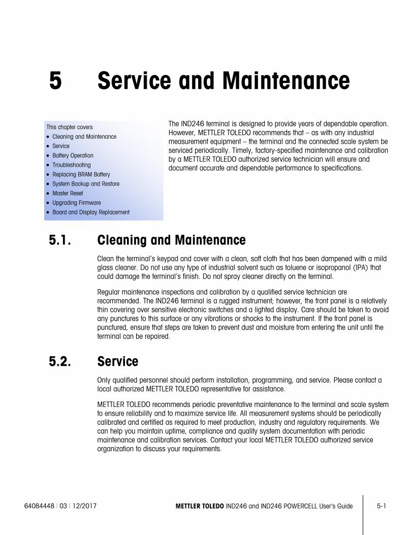
64084448 | 03 | 12/2017 METTLER TOLEDO IND246 and IND246 POWERCELL User's Guide
5-1
This chapter covers
• Cleaning and Maintenance
• Service
• Battery Operation
• Troubleshooting
• Replacing BRAM Battery
• System Backup and Restore
• Master Reset
• Upgrading Firmware
• Board and Display Replacement
5 Service and Maintenance The IND246 terminal is designed to provide years of dependable operation. However, METTLER TOLEDO recommends that – as with any industrial measurement equipment – the terminal and the connected scale system be serviced periodically. Timely, factory-specified maintenance and calibration by a METTLER TOLEDO authorized service technician will ensure and document accurate and dependable performance to specifications.
5.1. Cleaning and Maintenance Clean the terminal’s keypad and cover with a clean, soft cloth that has been dampened with a mild glass cleaner. Do not use any type of industrial solvent such as toluene or isopropanol (IPA) that could damage the terminal’s finish. Do not spray cleaner directly on the terminal.
Regular maintenance inspections and calibration by a qualified service technician are recommended. The IND246 terminal is a rugged instrument; however, the front panel is a relatively thin covering over sensitive electronic switches and a lighted display. Care should be taken to avoid any punctures to this surface or any vibrations or shocks to the instrument. If the front panel is punctured, ensure that steps are taken to prevent dust and moisture from entering the unit until the terminal can be repaired.
5.2. Service Only qualified personnel should perform installation, programming, and service. Please contact a local authorized METTLER TOLEDO representative for assistance.
METTLER TOLEDO recommends periodic preventative maintenance to the terminal and scale system to ensure reliability and to maximize service life. All measurement systems should be periodically calibrated and certified as required to meet production, industry and regulatory requirements. We can help you maintain uptime, compliance and quality system documentation with periodic maintenance and calibration services. Contact your local METTLER TOLEDO authorized service organization to discuss your requirements.
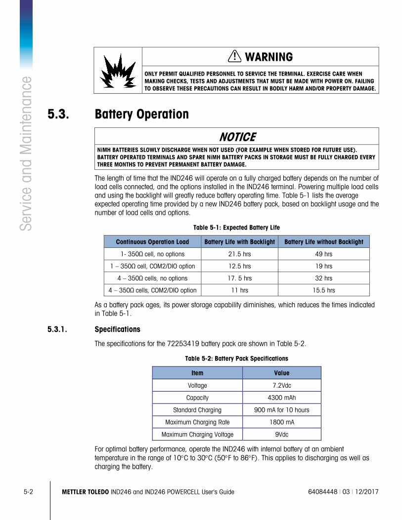
5-2
METTLER TOLEDO IND246 and IND246 POWERCELL User's Guide 64084448 | 03 | 12/2017
Serv
ice
and
Mai
nten
ance
WARNING ONLY PERMIT QUALIFIED PERSONNEL TO SERVICE THE TERMINAL. EXERCISE CARE WHEN MAKING CHECKS, TESTS AND ADJUSTMENTS THAT MUST BE MADE WITH POWER ON. FAILING TO OBSERVE THESE PRECAUTIONS CAN RESULT IN BODILY HARM AND/OR PROPERTY DAMAGE.
5.3. Battery Operation
NOTICE NiMH BATTERIES SLOWLY DISCHARGE WHEN NOT USED (FOR EXAMPLE WHEN STORED FOR FUTURE USE). BATTERY OPERATED TERMINALS AND SPARE NiMH BATTERY PACKS IN STORAGE MUST BE FULLY CHARGED EVERY THREE MONTHS TO PREVENT PERMANENT BATTERY DAMAGE.
The length of time that the IND246 will operate on a fully charged battery depends on the number of load cells connected, and the options installed in the IND246 terminal. Powering multiple load cells and using the backlight will greatly reduce battery operating time. Table 5-1 lists the average expected operating time provided by a new IND246 battery pack, based on backlight usage and the number of load cells and options.
Table 5-1: Expected Battery Life
Continuous Operation Load Battery Life with Backlight Battery Life without Backlight
1- 350Ω cell, no options 21.5 hrs 49 hrs
1 – 350Ω cell, COM2/DIO option 12.5 hrs 19 hrs
4 – 350Ω cells, no options 17. 5 hrs 32 hrs
4 – 350Ω cells, COM2/DIO option 11 hrs 15.5 hrs
As a battery pack ages, its power storage capability diminishes, which reduces the times indicated in Table 5-1.
5.3.1. Specifications
The specifications for the 72253419 battery pack are shown in Table 5-2.
Table 5-2: Battery Pack Specifications
Item Value
Voltage 7.2Vdc
Capacity 4300 mAh
Standard Charging 900 mA for 10 hours
Maximum Charging Rate 1800 mA
Maximum Charging Voltage 9Vdc
For optimal battery performance, operate the IND246 with internal battery at an ambient temperature in the range of 10°C to 30°C (50°F to 86°F). This applies to discharging as well as charging the battery.
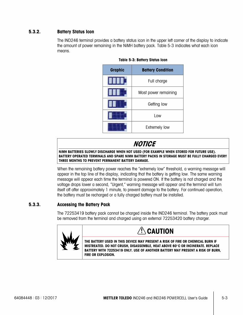
64084448 | 03 | 12/2017 METTLER TOLEDO IND246 and IND246 POWERCELL User's Guide
5-3
5.3.2. Battery Status Icon
The IND246 terminal provides a battery status icon in the upper left corner of the display to indicate the amount of power remaining in the NiMH battery pack. Table 5-3 indicates what each icon means.
Table 5-3: Battery Status Icon
Graphic Battery Condition
Full charge
Most power remaining
Getting low
Low
Extremely low
NOTICE NiMH BATTERIES SLOWLY DISCHARGE WHEN NOT USED (FOR EXAMPLE WHEN STORED FOR FUTURE USE). BATTERY OPERATED TERMINALS AND SPARE NiMH BATTERY PACKS IN STORAGE MUST BE FULLY CHARGED EVERY THREE MONTHS TO PREVENT PERMANENT BATTERY DAMAGE.
When the remaining battery power reaches the “extremely low” threshold, a warning message will appear in the top line of the display, indicating that the battery is getting low. The same warning message will appear each time the terminal is powered ON. If the battery is not charged and the voltage drops lower a second, “Urgent,” warning message will appear and the terminal will turn itself off after approximately 1 minute, to prevent damage to the battery. For continued operation, the battery must be recharged or a fully charged battery must be installed.
5.3.3. Accessing the Battery Pack
The 72253419 battery pack cannot be charged inside the IND246 terminal. The battery pack must be removed from the terminal and charged using an external 72253420 battery charger.
CAUTION THE BATTERY USED IN THIS DEVICE MAY PRESENT A RISK OF FIRE OR CHEMICAL BURN IF MISTREATED. DO NOT CRUSH, DISASSEMBLE, HEAT ABOVE 60°C OR INCINERATE. REPLACE BATTERY WITH 72253419 ONLY. USE OF ANOTHER BATTERY MAY PRESENT A RISK OF BURN, FIRE OR EXPLOSION.
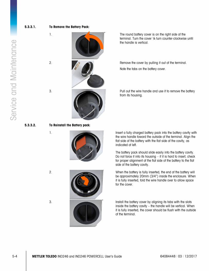
5-4
METTLER TOLEDO IND246 and IND246 POWERCELL User's Guide 64084448 | 03 | 12/2017
Serv
ice
and
Mai
nten
ance
5.3.3.1. To Remove the Battery Pack:
1.
The round battery cover is on the right side of the terminal. Turn the cover ¼ turn counter-clockwise until the handle is vertical.
2.
Remove the cover by pulling it out of the terminal.
Note the tabs on the battery cover.
3.
Pull out the wire handle and use it to remove the battery from its housing.
5.3.3.2. To Reinstall the Battery pack:
1.
Insert a fully charged battery pack into the battery cavity with the wire handle toward the outside of the terminal. Align the flat side of the battery with the flat side of the cavity, as indicated at left.
The battery pack should slide easily into the battery cavity. Do not force it into its housing – if it is hard to insert, check for proper alignment of the flat side of the battery to the flat side of the battery cavity.
2.
When the battery is fully inserted, the end of the battery will be approximately 20mm (3/4”) inside the enclosure. When it is fully inserted, fold the wire handle over to allow space for the cover.
3.
Install the battery cover by aligning its tabs with the slots inside the battery cavity – the handle will be vertical. When it is fully inserted, the cover should be flush with the outside of the terminal.
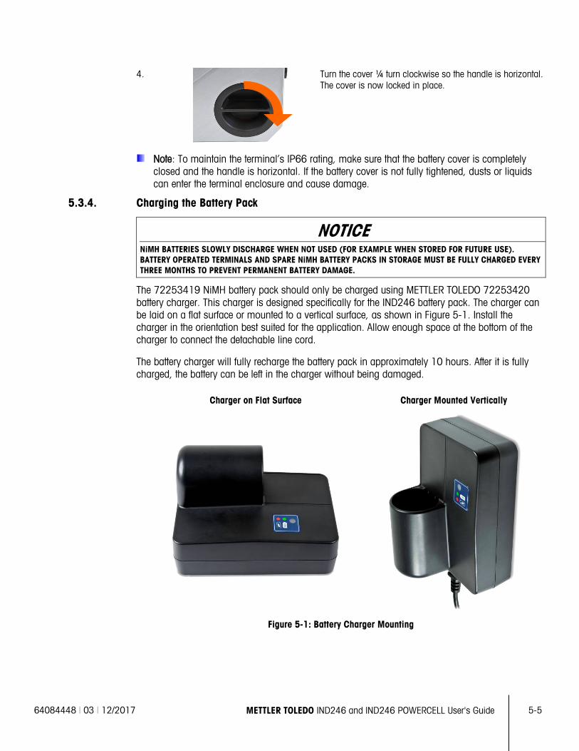
64084448 | 03 | 12/2017 METTLER TOLEDO IND246 and IND246 POWERCELL User's Guide
5-5
4.
Turn the cover ¼ turn clockwise so the handle is horizontal. The cover is now locked in place.
Note: To maintain the terminal’s IP66 rating, make sure that the battery cover is completely closed and the handle is horizontal. If the battery cover is not fully tightened, dusts or liquids can enter the terminal enclosure and cause damage.
5.3.4. Charging the Battery Pack
NOTICE NiMH BATTERIES SLOWLY DISCHARGE WHEN NOT USED (FOR EXAMPLE WHEN STORED FOR FUTURE USE). BATTERY OPERATED TERMINALS AND SPARE NiMH BATTERY PACKS IN STORAGE MUST BE FULLY CHARGED EVERY THREE MONTHS TO PREVENT PERMANENT BATTERY DAMAGE.
The 72253419 NiMH battery pack should only be charged using METTLER TOLEDO 72253420 battery charger. This charger is designed specifically for the IND246 battery pack. The charger can be laid on a flat surface or mounted to a vertical surface, as shown in Figure 5-1. Install the charger in the orientation best suited for the application. Allow enough space at the bottom of the charger to connect the detachable line cord.
The battery charger will fully recharge the battery pack in approximately 10 hours. After it is fully charged, the battery can be left in the charger without being damaged.
Charger on Flat Surface Charger Mounted Vertically
Figure 5-1: Battery Charger Mounting
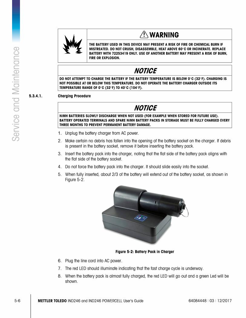
5-6
METTLER TOLEDO IND246 and IND246 POWERCELL User's Guide 64084448 | 03 | 12/2017
Serv
ice
and
Mai
nten
ance
WARNING THE BATTERY USED IN THIS DEVICE MAY PRESENT A RISK OF FIRE OR CHEMICAL BURN IF MISTREATED. DO NOT CRUSH, DISASSEMBLE, HEAT ABOVE 60°C OR INCINERATE. REPLACE BATTERY WITH 72253419 ONLY. USE OF ANOTHER BATTERY MAY PRESENT A RISK OF BURN, FIRE OR EXPLOSION.
NOTICE DO NOT ATTEMPT TO CHARGE THE BATTERY IF THE BATTERY TEMPERATURE IS BELOW 0°C (32°F). CHARGING IS NOT POSSIBLE AT OR BELOW THIS TEMPERATURE. DO NOT OPERATE THE BATTERY CHARGER OUTSIDE ITS TEMPERATURE RANGE OF 0°C (32°F) TO 40°C (104°F).
5.3.4.1. Charging Procedure
NOTICE NiMH BATTERIES SLOWLY DISCHARGE WHEN NOT USED (FOR EXAMPLE WHEN STORED FOR FUTURE USE). BATTERY OPERATED TERMINALS AND SPARE NiMH BATTERY PACKS IN STORAGE MUST BE FULLY CHARGED EVERY THREE MONTHS TO PREVENT PERMANENT BATTERY DAMAGE.
1. Unplug the battery charger from AC power.
2. Make certain no debris has fallen into the opening of the battery socket on the charger. If debris is present in the battery socket, remove it before inserting the battery pack.
3. Insert the battery pack into the charger, noting that the flat side of the battery pack aligns with the flat side of the battery socket.
4. Do not force the battery pack into the charger. It should slide easily into the socket.
5. When fully inserted, about 2/3 of the battery will extend out of the battery socket, as shown in Figure 5-2.
Figure 5-2: Battery Pack in Charger
6. Plug the line cord into AC power.
7. The red LED should illuminate indicating that the fast charge cycle is underway.
8. When the battery pack is almost fully charged, the red LED will go out and a green Led will be shown.
64084448 | 03 | 12/2017 METTLER TOLEDO IND246 and IND246 POWERCELL User's Guide
5-7
9. The charger will continue to provide a small “trickle” charge to the battery until the battery is removed.
10. When charging is complete, remove the battery pack from the charger and reinstall into the IND246 terminal, as described above.
5.3.5. Disposing of a Depleted Battery Pack
As a result of normal use over a period of time, the available power in the 72253419 NiMH battery pack will be reduced and it will lose its ability to power the IND246 terminal for an extended time. When this occurs, the battery pack should be replaced with a new battery pack and the original battery pack must be disposed of.
CAUTION DISPOSE OF USED BATTERY PROMPTLY. KEEP AWAY FROM CHILDREN. DO NOT DISASSEMBLE AND DO NOT DISPOSE OF IN FIRE.
Follow local laws and regulations regarding the disposal of the NiMH battery pack.
5.4. Troubleshooting Troubleshooting activities described here are to assist in identifying whether the problem is in the IND246 terminal or has an external cause.
• Blank Display
• On/Off Key Test
• Power Test
• Coin Cell Battery Test
• Problem Diagnosis
• Error Codes and Error Messages
• Internal Diagnostic Testing
5.4.1. Blank Display
If the display on the IND246 terminal appears to be blank, first confirm if the display is actually blank or if the backlight is simply off or if the contrast adjustment is incorrect. Even with the backlight off or a poor contrast setting, changing weight digits should still be barely visible with a change in weight.
If changing weight digits can still be seen, check the contrast and backlight settings in setup. Moving the terminal to a very bright environment may help to navigate setup easier.
If no changing digits can be seen, proceed to the Power Test.
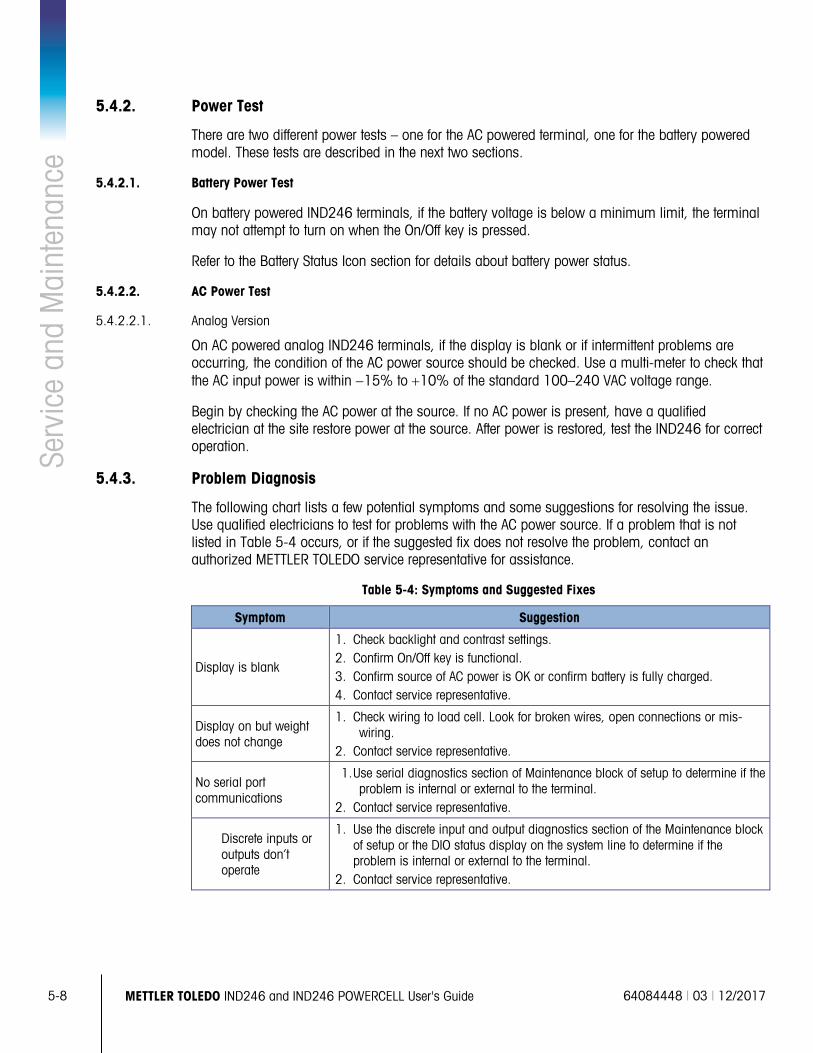
5-8
METTLER TOLEDO IND246 and IND246 POWERCELL User's Guide 64084448 | 03 | 12/2017
Serv
ice
and
Mai
nten
ance
5.4.2. Power Test
There are two different power tests – one for the AC powered terminal, one for the battery powered model. These tests are described in the next two sections.
5.4.2.1. Battery Power Test
On battery powered IND246 terminals, if the battery voltage is below a minimum limit, the terminal may not attempt to turn on when the On/Off key is pressed.
Refer to the Battery Status Icon section for details about battery power status.
5.4.2.2. AC Power Test
5.4.2.2.1. Analog Version
On AC powered analog IND246 terminals, if the display is blank or if intermittent problems are occurring, the condition of the AC power source should be checked. Use a multi-meter to check that the AC input power is within −15% to +10% of the standard 100–240 VAC voltage range.
Begin by checking the AC power at the source. If no AC power is present, have a qualified electrician at the site restore power at the source. After power is restored, test the IND246 for correct operation.
5.4.3. Problem Diagnosis
The following chart lists a few potential symptoms and some suggestions for resolving the issue. Use qualified electricians to test for problems with the AC power source. If a problem that is not listed in Table 5-4 occurs, or if the suggested fix does not resolve the problem, contact an authorized METTLER TOLEDO service representative for assistance.
Table 5-4: Symptoms and Suggested Fixes
Symptom Suggestion
Display is blank
1. Check backlight and contrast settings. 2. Confirm On/Off key is functional. 3. Confirm source of AC power is OK or confirm battery is fully charged. 4. Contact service representative.
Display on but weight does not change
1. Check wiring to load cell. Look for broken wires, open connections or mis-wiring.
2. Contact service representative.
No serial port communications
1. Use serial diagnostics section of Maintenance block of setup to determine if the problem is internal or external to the terminal.
2. Contact service representative.
Discrete inputs or outputs don’t operate
1. Use the discrete input and output diagnostics section of the Maintenance block of setup or the DIO status display on the system line to determine if the problem is internal or external to the terminal.
2. Contact service representative.
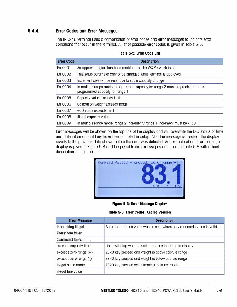
64084448 | 03 | 12/2017 METTLER TOLEDO IND246 and IND246 POWERCELL User's Guide
5-9
5.4.4. Error Codes and Error Messages
The IND246 terminal uses a combination of error codes and error messages to indicate error conditions that occur in the terminal. A list of possible error codes is given in Table 5-5.
Table 5-5: Error Code List
Error Code Description
Err 0001 An approval region has been enabled and the W&M switch is off
Err 0002 This setup parameter cannot be changed while terminal is approved
Err 0003 Increment size will be reset due to scale capacity change
Err 0004 In multiple range mode, programmed capacity for range 2 must be greater than the programmed capacity for range 1
Err 0005 Capacity value exceeds limit
Err 0006 Calibration weight exceeds range
Err 0007 GEO value exceeds limit
Err 0008 Illegal capacity value
Err 0009 In multiple range mode, range 2 increment / range 1 increment must be < 50
Error messages will be shown on the top line of the display and will overwrite the DIO status or time and date information if they have been enabled in setup. After the message is cleared, the display reverts to the previous data shown before the error was detected. An example of an error message display is given in Figure 5-8 and the possible error messages are listed in Table 5-6 with a brief description of the error.
Figure 5-3: Error Message Display
Table 5-6: Error Codes, Analog Version
Error Message Description
Input string illegal An alpha-numeric value was entered where only a numeric value is valid
Preset tare failed
Command failed - . . .
exceeds capacity limit Unit switching would result in a value too large to display
exceeds zero range (+) ZERO key pressed and weight is above capture range
exceeds zero range (-) ZERO key pressed and weight is below capture range
illegal scale mode ZERO key pressed while terminal is in net mode
illegal tare value
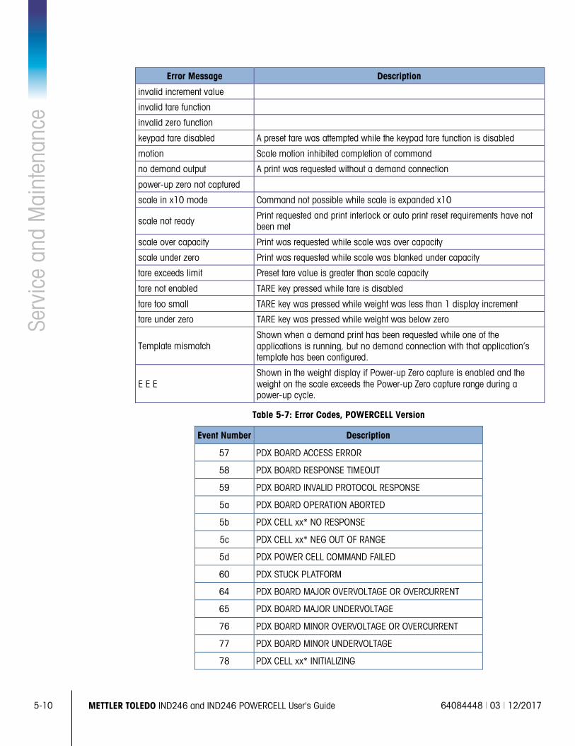
5-10
METTLER TOLEDO IND246 and IND246 POWERCELL User's Guide 64084448 | 03 | 12/2017
Serv
ice
and
Mai
nten
ance
Error Message Description
invalid increment value
invalid tare function
invalid zero function
keypad tare disabled A preset tare was attempted while the keypad tare function is disabled
motion Scale motion inhibited completion of command
no demand output A print was requested without a demand connection
power-up zero not captured
scale in x10 mode Command not possible while scale is expanded x10
scale not ready Print requested and print interlock or auto print reset requirements have not been met
scale over capacity Print was requested while scale was over capacity
scale under zero Print was requested while scale was blanked under capacity
tare exceeds limit Preset tare value is greater than scale capacity
tare not enabled TARE key pressed while tare is disabled
tare too small TARE key was pressed while weight was less than 1 display increment
tare under zero TARE key was pressed while weight was below zero
Template mismatch Shown when a demand print has been requested while one of the applications is running, but no demand connection with that application’s template has been configured.
E E E Shown in the weight display if Power-up Zero capture is enabled and the weight on the scale exceeds the Power-up Zero capture range during a power-up cycle.
Table 5-7: Error Codes, POWERCELL Version
Event Number Description
57 PDX BOARD ACCESS ERROR
58 PDX BOARD RESPONSE TIMEOUT
59 PDX BOARD INVALID PROTOCOL RESPONSE
5a PDX BOARD OPERATION ABORTED
5b PDX CELL xx* NO RESPONSE
5c PDX CELL xx* NEG OUT OF RANGE
5d PDX POWER CELL COMMAND FAILED
60 PDX STUCK PLATFORM
64 PDX BOARD MAJOR OVERVOLTAGE OR OVERCURRENT
65 PDX BOARD MAJOR UNDERVOLTAGE
76 PDX BOARD MINOR OVERVOLTAGE OR OVERCURRENT
77 PDX BOARD MINOR UNDERVOLTAGE
78 PDX CELL xx* INITIALIZING
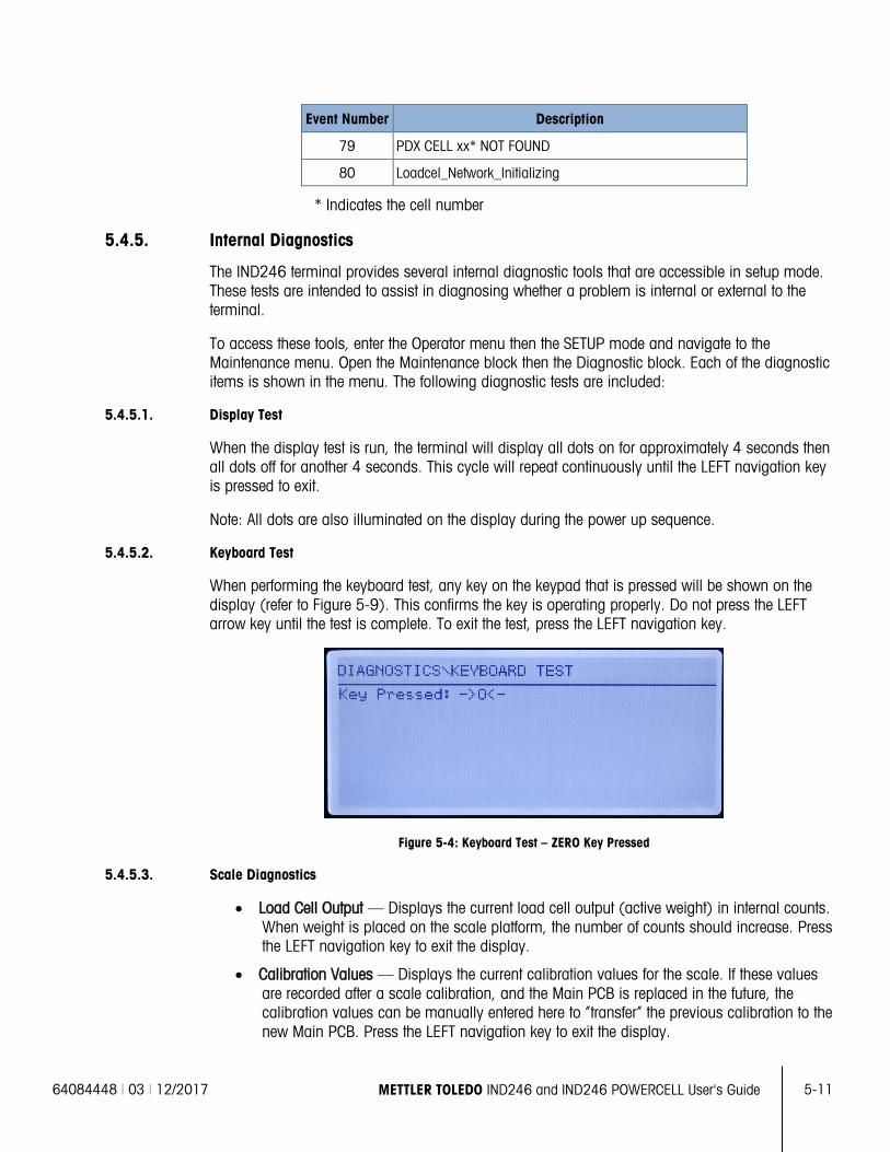
64084448 | 03 | 12/2017 METTLER TOLEDO IND246 and IND246 POWERCELL User's Guide
5-11
Event Number Description
79 PDX CELL xx* NOT FOUND
80 Loadcel_Network_Initializing
* Indicates the cell number
5.4.5. Internal Diagnostics
The IND246 terminal provides several internal diagnostic tools that are accessible in setup mode. These tests are intended to assist in diagnosing whether a problem is internal or external to the terminal.
To access these tools, enter the Operator menu then the SETUP mode and navigate to the Maintenance menu. Open the Maintenance block then the Diagnostic block. Each of the diagnostic items is shown in the menu. The following diagnostic tests are included:
5.4.5.1. Display Test
When the display test is run, the terminal will display all dots on for approximately 4 seconds then all dots off for another 4 seconds. This cycle will repeat continuously until the LEFT navigation key is pressed to exit.
Note: All dots are also illuminated on the display during the power up sequence.
5.4.5.2. Keyboard Test
When performing the keyboard test, any key on the keypad that is pressed will be shown on the display (refer to Figure 5-9). This confirms the key is operating properly. Do not press the LEFT arrow key until the test is complete. To exit the test, press the LEFT navigation key.
Figure 5-4: Keyboard Test – ZERO Key Pressed
5.4.5.3. Scale Diagnostics
• Load Cell Output — Displays the current load cell output (active weight) in internal counts. When weight is placed on the scale platform, the number of counts should increase. Press the LEFT navigation key to exit the display.
• Calibration Values — Displays the current calibration values for the scale. If these values are recorded after a scale calibration, and the Main PCB is replaced in the future, the calibration values can be manually entered here to “transfer” the previous calibration to the new Main PCB. Press the LEFT navigation key to exit the display.
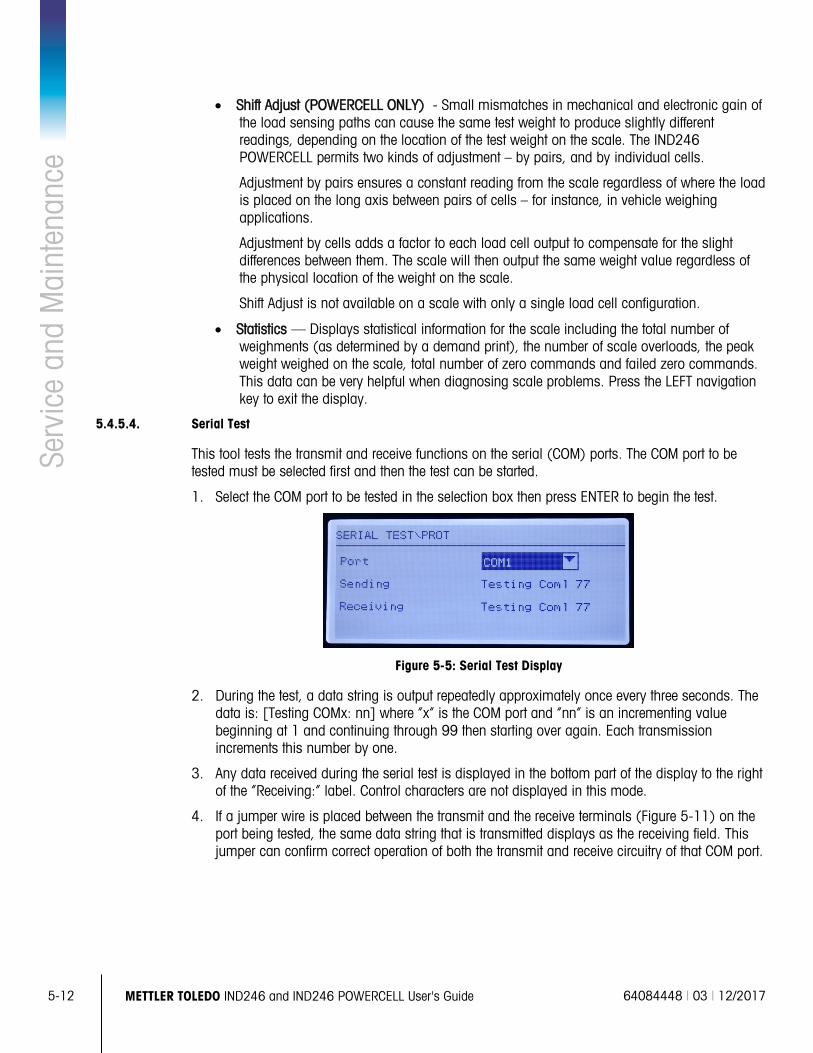
5-12
METTLER TOLEDO IND246 and IND246 POWERCELL User's Guide 64084448 | 03 | 12/2017
Serv
ice
and
Mai
nten
ance
• Shift Adjust (POWERCELL ONLY) - Small mismatches in mechanical and electronic gain of
the load sensing paths can cause the same test weight to produce slightly different readings, depending on the location of the test weight on the scale. The IND246 POWERCELL permits two kinds of adjustment – by pairs, and by individual cells.
Adjustment by pairs ensures a constant reading from the scale regardless of where the load is placed on the long axis between pairs of cells – for instance, in vehicle weighing applications.
Adjustment by cells adds a factor to each load cell output to compensate for the slight differences between them. The scale will then output the same weight value regardless of the physical location of the weight on the scale.
Shift Adjust is not available on a scale with only a single load cell configuration.
• Statistics — Displays statistical information for the scale including the total number of weighments (as determined by a demand print), the number of scale overloads, the peak weight weighed on the scale, total number of zero commands and failed zero commands. This data can be very helpful when diagnosing scale problems. Press the LEFT navigation key to exit the display.
5.4.5.4. Serial Test
This tool tests the transmit and receive functions on the serial (COM) ports. The COM port to be tested must be selected first and then the test can be started.
1. Select the COM port to be tested in the selection box then press ENTER to begin the test.
Figure 5-5: Serial Test Display
2. During the test, a data string is output repeatedly approximately once every three seconds. The data is: [Testing COMx: nn] where “x” is the COM port and “nn” is an incrementing value beginning at 1 and continuing through 99 then starting over again. Each transmission increments this number by one.
3. Any data received during the serial test is displayed in the bottom part of the display to the right of the “Receiving:” label. Control characters are not displayed in this mode.
4. If a jumper wire is placed between the transmit and the receive terminals (Figure 5-11) on the port being tested, the same data string that is transmitted displays as the receiving field. This jumper can confirm correct operation of both the transmit and receive circuitry of that COM port.
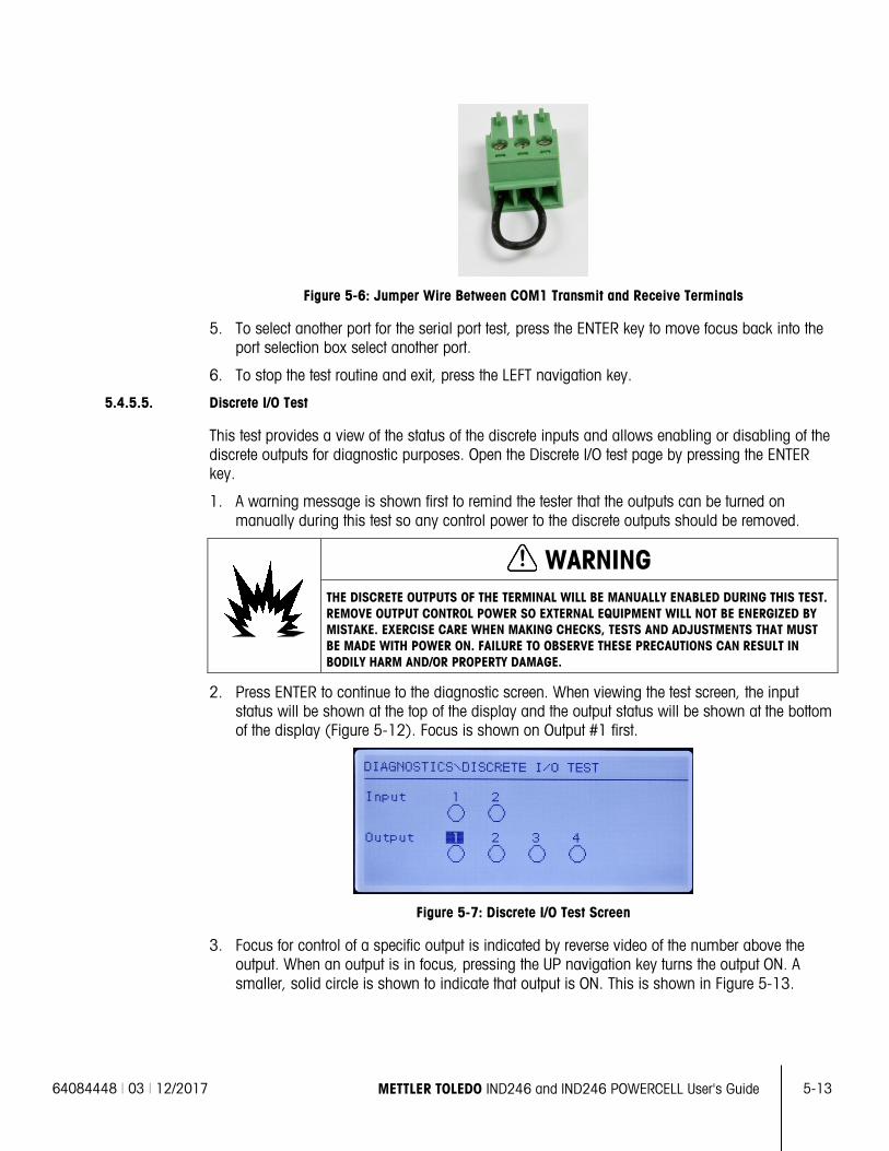
64084448 | 03 | 12/2017 METTLER TOLEDO IND246 and IND246 POWERCELL User's Guide
5-13
Figure 5-6: Jumper Wire Between COM1 Transmit and Receive Terminals
5. To select another port for the serial port test, press the ENTER key to move focus back into the port selection box select another port.
6. To stop the test routine and exit, press the LEFT navigation key.
5.4.5.5. Discrete I/O Test
This test provides a view of the status of the discrete inputs and allows enabling or disabling of the discrete outputs for diagnostic purposes. Open the Discrete I/O test page by pressing the ENTER key.
1. A warning message is shown first to remind the tester that the outputs can be turned on manually during this test so any control power to the discrete outputs should be removed.
WARNING THE DISCRETE OUTPUTS OF THE TERMINAL WILL BE MANUALLY ENABLED DURING THIS TEST. REMOVE OUTPUT CONTROL POWER SO EXTERNAL EQUIPMENT WILL NOT BE ENERGIZED BY MISTAKE. EXERCISE CARE WHEN MAKING CHECKS, TESTS AND ADJUSTMENTS THAT MUST BE MADE WITH POWER ON. FAILURE TO OBSERVE THESE PRECAUTIONS CAN RESULT IN BODILY HARM AND/OR PROPERTY DAMAGE.
2. Press ENTER to continue to the diagnostic screen. When viewing the test screen, the input status will be shown at the top of the display and the output status will be shown at the bottom of the display (Figure 5-12). Focus is shown on Output #1 first.
Figure 5-7: Discrete I/O Test Screen
3. Focus for control of a specific output is indicated by reverse video of the number above the output. When an output is in focus, pressing the UP navigation key turns the output ON. A smaller, solid circle is shown to indicate that output is ON. This is shown in Figure 5-13.
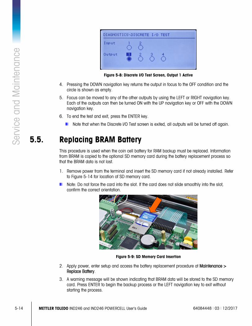
5-14
METTLER TOLEDO IND246 and IND246 POWERCELL User's Guide 64084448 | 03 | 12/2017
Serv
ice
and
Mai
nten
ance
Figure 5-8: Discrete I/O Test Screen, Output 1 Active
4. Pressing the DOWN navigation key returns the output in focus to the OFF condition and the circle is shown as empty.
5. Focus can be moved to any of the other outputs by using the LEFT or RIGHT navigation key. Each of the outputs can then be turned ON with the UP navigation key or OFF with the DOWN navigation key.
6. To end the test and exit, press the ENTER key.
Note that when the Discrete I/O Test screen is exited, all outputs will be turned off again.
5.5. Replacing BRAM Battery This procedure is used when the coin cell battery for RAM backup must be replaced. Information from BRAM is copied to the optional SD memory card during the battery replacement process so that the BRAM data is not lost.
1. Remove power from the terminal and insert the SD memory card if not already installed. Refer to Figure 5-14 for location of SD memory card.
Note: Do not force the card into the slot. If the card does not slide smoothly into the slot, confirm the correct orientation.
Figure 5-9: SD Memory Card Insertion
2. Apply power, enter setup and access the battery replacement procedure at Maintenance > Replace Battery.
3. A warning message will be shown indicating that BRAM data will be stored to the SD memory card. Press ENTER to begin the backup process or the LEFT navigation key to exit without starting the process.
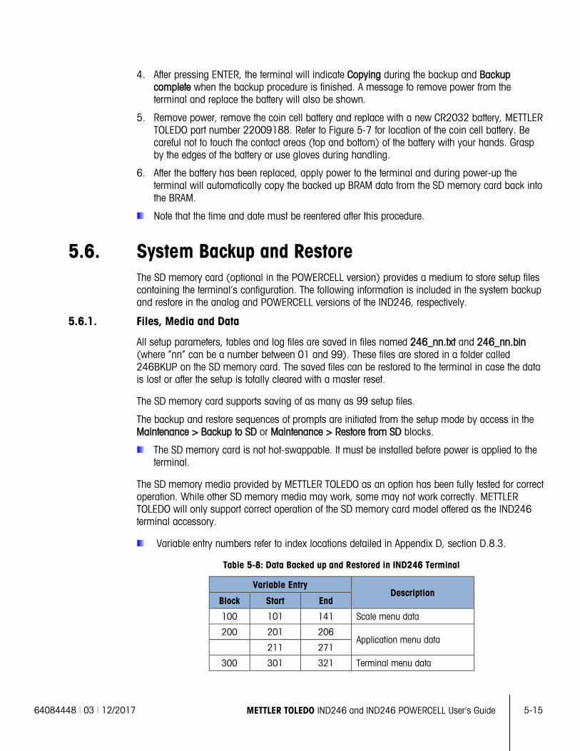
64084448 | 03 | 12/2017 METTLER TOLEDO IND246 and IND246 POWERCELL User's Guide
5-15
4. After pressing ENTER, the terminal will indicate Copying during the backup and Backup complete when the backup procedure is finished. A message to remove power from the terminal and replace the battery will also be shown.
5. Remove power, remove the coin cell battery and replace with a new CR2032 battery, METTLER TOLEDO part number 22009188. Refer to Figure 5-7 for location of the coin cell battery. Be careful not to touch the contact areas (top and bottom) of the battery with your hands. Grasp by the edges of the battery or use gloves during handling.
6. After the battery has been replaced, apply power to the terminal and during power-up the terminal will automatically copy the backed up BRAM data from the SD memory card back into the BRAM.
Note that the time and date must be reentered after this procedure.
5.6. System Backup and Restore The SD memory card (optional in the POWERCELL version) provides a medium to store setup files containing the terminal’s configuration. The following information is included in the system backup and restore in the analog and POWERCELL versions of the IND246, respectively.
5.6.1. Files, Media and Data
All setup parameters, tables and log files are saved in files named 246_nn.txt and 246_nn.bin (where “nn” can be a number between 01 and 99). These files are stored in a folder called 246BKUP on the SD memory card. The saved files can be restored to the terminal in case the data is lost or after the setup is totally cleared with a master reset.
The SD memory card supports saving of as many as 99 setup files.
The backup and restore sequences of prompts are initiated from the setup mode by access in the Maintenance > Backup to SD or Maintenance > Restore from SD blocks.
The SD memory card is not hot-swappable. It must be installed before power is applied to the terminal.
The SD memory media provided by METTLER TOLEDO as an option has been fully tested for correct operation. While other SD memory media may work, some may not work correctly. METTLER TOLEDO will only support correct operation of the SD memory card model offered as the IND246 terminal accessory.
Variable entry numbers refer to index locations detailed in Appendix D, section D.8.3.
Table 5-8: Data Backed up and Restored in IND246 Terminal
Variable Entry Description
Block Start End
100 101 141 Scale menu data
200 201 206 Application menu data
211 271
300 301 321 Terminal menu data
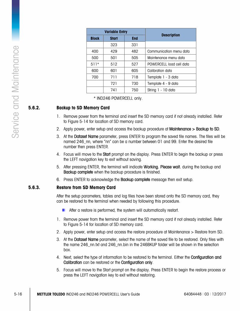
5-16
METTLER TOLEDO IND246 and IND246 POWERCELL User's Guide 64084448 | 03 | 12/2017
Serv
ice
and
Mai
nten
ance
Variable Entry Description
Block Start End
323 331
400 429 482 Communication menu data
500 501 505 Maintenance menu data
511* 512 527 POWERCELL load cell data
600 601 605 Calibration data
700 711 718 Template 1 - 3 data
721 730 Template 4 - 9 data
741 750 String 1 - 10 data
* IND246 POWERCELL only.
5.6.2. Backup to SD Memory Card
1. Remove power from the terminal and insert the SD memory card if not already installed. Refer to Figure 5-14 for location of SD memory card.
2. Apply power, enter setup and access the backup procedure at Maintenance > Backup to SD.
3. At the Dataset Name parameter, press ENTER to program the saved file names. The files will be named 246_nn, where “nn” can be a number between 01 and 99. Enter the desired file number then press ENTER.
4. Focus will move to the Start prompt on the display. Press ENTER to begin the backup or press the LEFT navigation key to exit without saving.
5. After pressing ENTER, the terminal will indicate Working. Please wait. during the backup and Backup complete when the backup procedure is finished.
6. Press ENTER to acknowledge the Backup complete message then exit setup.
5.6.3. Restore from SD Memory Card
After the setup parameters, tables and log files have been stored onto the SD memory card, they can be restored to the terminal when needed by following this procedure.
After a restore is performed, the system will automatically restart.
1. Remove power from the terminal and insert the SD memory card if not already installed. Refer to Figure 5-14 for location of SD memory card.
2. Apply power, enter setup and access the restore procedure at Maintenance > Restore from SD.
3. At the Dataset Name parameter, select the name of the saved file to be restored. Only files with the name 246_nn.txt and 246_nn.bin in the 246BKUP folder will be shown in the selection box.
4. Next, select the type of information to be restored to the terminal. Either the Configuration and Calibration can be restored or the Configuration only.
5. Focus will move to the Start prompt on the display. Press ENTER to begin the restore process or press the LEFT navigation key to exit without restoring.
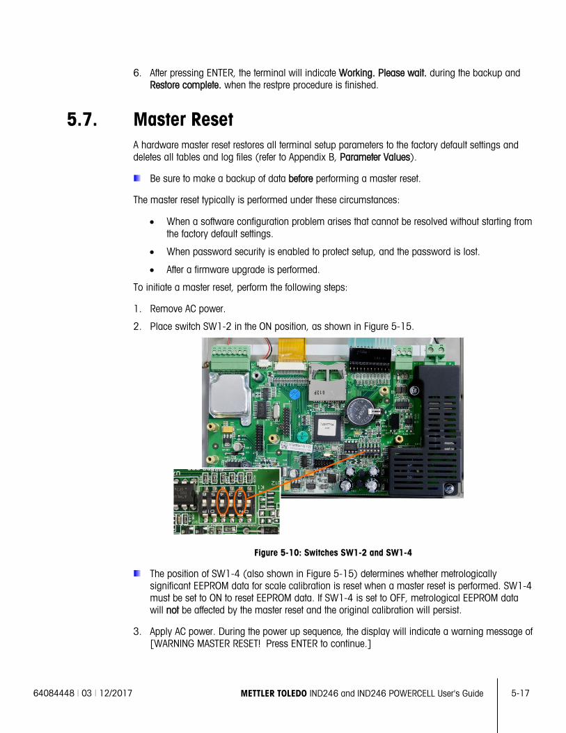
64084448 | 03 | 12/2017 METTLER TOLEDO IND246 and IND246 POWERCELL User's Guide
5-17
6. After pressing ENTER, the terminal will indicate Working. Please wait. during the backup and Restore complete. when the restpre procedure is finished.
5.7. Master Reset A hardware master reset restores all terminal setup parameters to the factory default settings and deletes all tables and log files (refer to Appendix B, Parameter Values).
Be sure to make a backup of data before performing a master reset.
The master reset typically is performed under these circumstances:
• When a software configuration problem arises that cannot be resolved without starting from the factory default settings.
• When password security is enabled to protect setup, and the password is lost.
• After a firmware upgrade is performed.
To initiate a master reset, perform the following steps:
1. Remove AC power.
2. Place switch SW1-2 in the ON position, as shown in Figure 5-15.
Figure 5-10: Switches SW1-2 and SW1-4
The position of SW1-4 (also shown in Figure 5-15) determines whether metrologically significant EEPROM data for scale calibration is reset when a master reset is performed. SW1-4 must be set to ON to reset EEPROM data. If SW1-4 is set to OFF, metrological EEPROM data will not be affected by the master reset and the original calibration will persist.
3. Apply AC power. During the power up sequence, the display will indicate a warning message of [WARNING MASTER RESET! Press ENTER to continue.]
5-18
METTLER TOLEDO IND246 and IND246 POWERCELL User's Guide 64084448 | 03 | 12/2017
Serv
ice
and
Mai
nten
ance
4. Press ENTER to perform a master reset. When the reset is complete, the screen will return to the
normal weight display.
OR
To exit without a master reset, do not press ENTER.
5. Remove AC power.
6. Return SW1-2 (and, if it was changed, SW1-4) to their original OFF positions.
7. Reapply AC power.
5.8. Upgrading Firmware If a new 246A0nn.hex (IND246 analog) or 246P0nn.hex (IND246 POWERCELL) file is copied to the SD Memory card from a PC, the firmware can then be updated by the following procedure.
1. Remove power from the terminal and insert the SD memory card with the “246A0nn.hex” file copied to it into the SD memory card slot on the Main Board. Refer to Figure 5-14 for location of the SD memory slot.
2. Power up the terminal and access Setup > Maintenance > Install SW Update.
3. A message of [WARNING! Install new software from SD memory?] will be shown on the display. To exit without performing the firmware upgrade, press the LEFT navigation key.
4. To perform the upgrade, in the File Name parameter, select the firmware file to be uploaded. Only files with the format 246A0xx.hex on the SD card will be displayed.
5. With the desired file selected, press ENTER.
6. The display will show [Updating] for approximately 30 seconds then a power up cycle will be started.
7. After the power cycle, the upgrade is complete.
To eliminate potential memory errors, it is recommended that a Master Reset be performed after updating the firmware.
5.9. Board and Display Replacement This section describes the recommended procedures for removal and installation of option boards, the main board and the display module. Before beginning any of these procedures:
1. Perform a backup of all setup parameters with InSite SL or InSite CSL program.
2. Remove power from the terminal. Unplug the AC line cord on the AC version and remove the battery pack from the battery version.
3. Open the enclosure to access the internal electronics. Refer to the Installation Manual for details on opening the enclosure.
4. When handling any electronic boards or modules, use a grounding strap to prevent risk of electrostatic discharge damage.
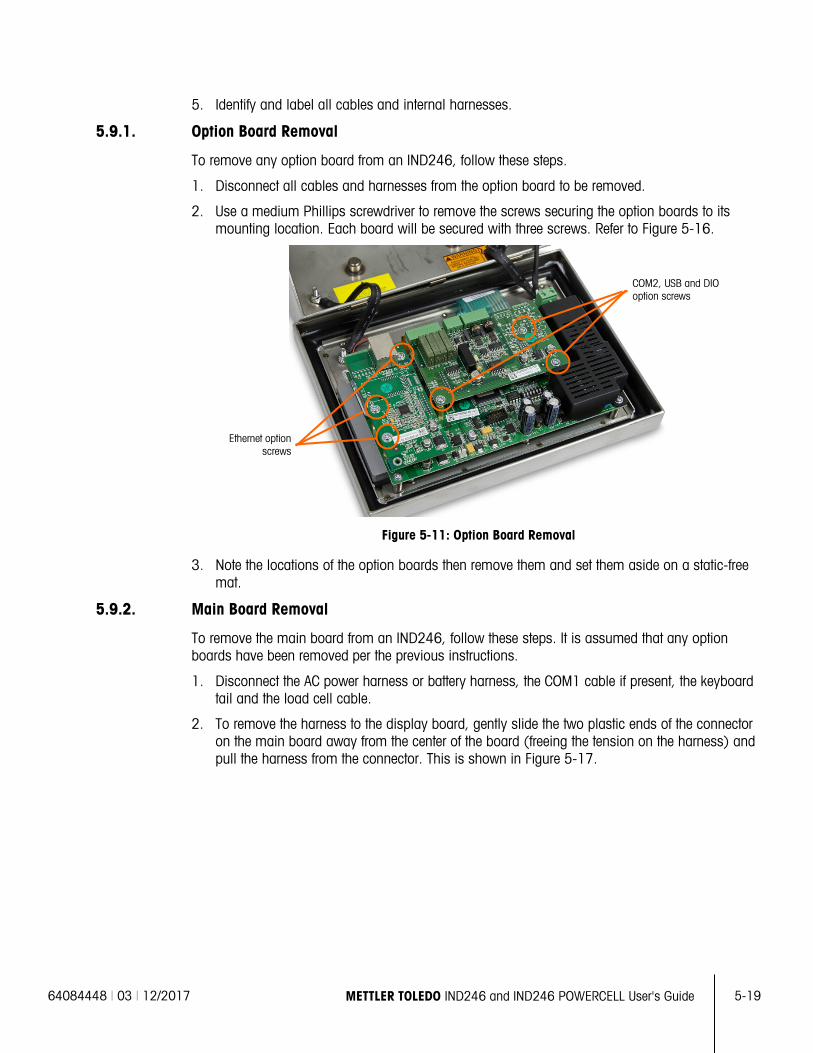
64084448 | 03 | 12/2017 METTLER TOLEDO IND246 and IND246 POWERCELL User's Guide
5-19
5. Identify and label all cables and internal harnesses.
5.9.1. Option Board Removal
To remove any option board from an IND246, follow these steps.
1. Disconnect all cables and harnesses from the option board to be removed.
2. Use a medium Phillips screwdriver to remove the screws securing the option boards to its mounting location. Each board will be secured with three screws. Refer to Figure 5-16.
Figure 5-11: Option Board Removal
3. Note the locations of the option boards then remove them and set them aside on a static-free mat.
5.9.2. Main Board Removal
To remove the main board from an IND246, follow these steps. It is assumed that any option boards have been removed per the previous instructions.
1. Disconnect the AC power harness or battery harness, the COM1 cable if present, the keyboard tail and the load cell cable.
2. To remove the harness to the display board, gently slide the two plastic ends of the connector on the main board away from the center of the board (freeing the tension on the harness) and pull the harness from the connector. This is shown in Figure 5-17.
Ethernet option screws
COM2, USB and DIO option screws
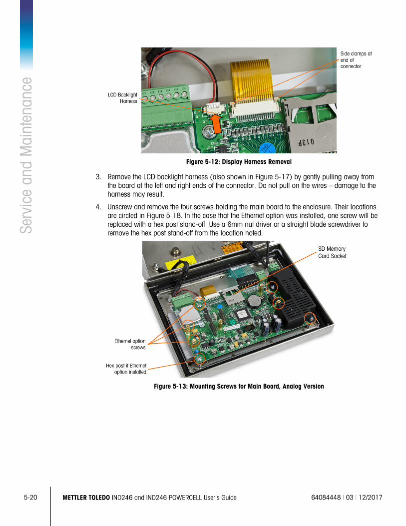
5-20
METTLER TOLEDO IND246 and IND246 POWERCELL User's Guide 64084448 | 03 | 12/2017
Serv
ice
and
Mai
nten
ance
Figure 5-12: Display Harness Removal
3. Remove the LCD backlight harness (also shown in Figure 5-17) by gently pulling away from the board at the left and right ends of the connector. Do not pull on the wires – damage to the harness may result.
4. Unscrew and remove the four screws holding the main board to the enclosure. Their locations are circled in Figure 5-18. In the case that the Ethernet option was installed, one screw will be replaced with a hex post stand-off. Use a 6mm nut driver or a straight blade screwdriver to remove the hex post stand-off from the location noted.
Figure 5-13: Mounting Screws for Main Board, Analog Version
Hex post if Ethernet option installed
SD Memory Card Socket
Ethernet option screws
LCD Backlight Harness
Side clamps at end of connector
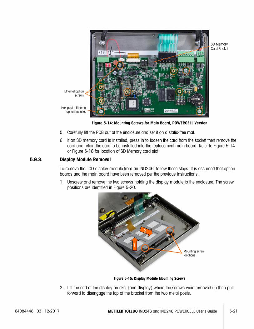
64084448 | 03 | 12/2017 METTLER TOLEDO IND246 and IND246 POWERCELL User's Guide
5-21
Figure 5-14: Mounting Screws for Main Board, POWERCELL Version
5. Carefully lift the PCB out of the enclosure and set it on a static-free mat.
6. If an SD memory card is installed, press in to loosen the card from the socket then remove the card and retain the card to be installed into the replacement main board. Refer to Figure 5-14 or Figure 5-18 for location of SD Memory card slot.
5.9.3. Display Module Removal
To remove the LCD display module from an IND246, follow these steps. It is assumed that option boards and the main board have been removed per the previous instructions.
1. Unscrew and remove the two screws holding the display module to the enclosure. The screw positions are identified in Figure 5-20.
Figure 5-15: Display Module Mounting Screws
2. Lift the end of the display bracket (and display) where the screws were removed up then pull forward to disengage the top of the bracket from the two metal posts.
Mounting screw locations
1
2
Hex post if Ethernet option installed
Ethernet option screws
SD Memory Card Socket
5-22
METTLER TOLEDO IND246 and IND246 POWERCELL User's Guide 64084448 | 03 | 12/2017
Serv
ice
and
Mai
nten
ance
3. Carefully remove the display module and bracket from the enclosure and set on a static-free
mat.
5.9.4. Display Module Installation
To install the LCD display module into an IND246, follow these steps. It is assumed that option boards and the main board have been removed per the previous instructions.
1. Make sure the display gasket on the inside of the front cover is intact. Replace if necessary.
2. Clean the inside of the display window and the front of the display with a mild window cleaner and a soft, lint-free cloth.
3. Place the LCD display module into the display bracket with the display and backlight harnesses oriented as shown in Figure 5-20.
4. While keeping the screw-end of the bracket lifted slightly, press the opposite end of the display bracket onto the two metal posts.
5. Lower the display and bracket into place.
6. Install the two screws holding the display module to the enclosure. The screws are identified in Figure 5-20.
All mounting screws should be installed with 23 inch pounds (2.6 Nm) of torque.
5.9.5. Main PCB Installation
To install the main board into an IND246, follow these steps. It is assumed that option boards have been removed per the previous instructions.
1. Install the SD memory card from the previous main board (if used).
2. Position the main board over the four screw holes in the terminal enclosure identified in Figure 5-18.
3. Install the four screws. Note that if the Ethernet option is to be used, one of the screws is replaced with a hex post stand-off. Refer to Figure 5-18 for the location of the hex post stand-off.
All mounting screws and the hex post stand-off should be installed with 23 inch pounds (2.6 Nm) of torque.
4. Reconnect the load cell cable, backlight harness, display harness, keyboard tail, COM1 cable and the power harness connections.
5.9.6. Option PCB Installation
1. To install any option boards into an IND246, follow these steps.
2. Position the option board over the appropriate connector on the main board and the three mounting holes identified in Figure 5-16.
3. Gently press the option board down so that all the pins on the main board connector slide into the socket on the bottom of the option board. When properly installed, each pin will insert into a corresponding hole in the connector. Refer to Figure 5-21
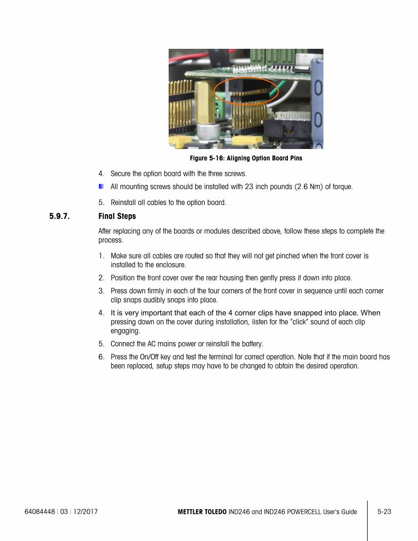
64084448 | 03 | 12/2017 METTLER TOLEDO IND246 and IND246 POWERCELL User's Guide
5-23
Figure 5-16: Aligning Option Board Pins
4. Secure the option board with the three screws.
All mounting screws should be installed with 23 inch pounds (2.6 Nm) of torque.
5. Reinstall all cables to the option board.
5.9.7. Final Steps
After replacing any of the boards or modules described above, follow these steps to complete the process.
1. Make sure all cables are routed so that they will not get pinched when the front cover is installed to the enclosure.
2. Position the front cover over the rear housing then gently press it down into place.
3. Press down firmly in each of the four corners of the front cover in sequence until each corner clip snaps audibly snaps into place.
4. It is very important that each of the 4 corner clips have snapped into place. When pressing down on the cover during installation, listen for the “click” sound of each clip engaging.
5. Connect the AC mains power or reinstall the battery.
6. Press the On/Off key and test the terminal for correct operation. Note that if the main board has been replaced, setup steps may have to be changed to obtain the desired operation.

64084448 | 03 | 12/2017 METTLER TOLEDO IND246 and IND246 POWERCELL User's Guide A-1
A Default Templates
A.1. Basic Functionality Template 1 – Multiple Line G T N
Element Data F-Code
1 Gross Weight 6
2 New Line 9
3 Tare Weight 21
4 New Line 9
5 Net Weight 8
6 New Line 9
7 End of template 5
Template 2 – Multiple Line Scale ID, T & D, G T N
Element Data F-Code
1 Scale Name 10
2 New Line 9
3 Time 22
4 New Line 9
5 Date 3
6 New Line 9
7 Gross Weight 6
8 New Line 9
9 Tare Weight 21
10 New Line 9
11 Net Weight 8
12 New Line 9
13 End of template 5
13.73 kg 2.00 kg PT 11.73 kg N
Scale 1 17:02:23 29/Mar/2012 44.01 kg 13.73 kg T 30.28 kg N
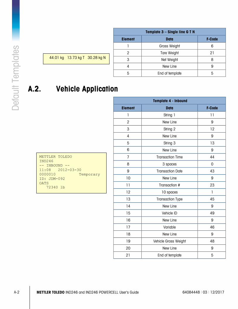
A-2 METTLER TOLEDO IND246 and IND246 POWERCELL User's Guide 64084448 | 03 | 12/2017
Def
ault
Tem
plat
es
Template 3 – Single line G T N
Element Data F-Code
1 Gross Weight 6
2 Tare Weight 21
3 Net Weight 8
4 New Line 9
5 End of template 5
A.2. Vehicle Application Template 4 - Inbound
Element Data F-Code
1 String 1 11
2 New Line 9
3 String 2 12
4 New Line 9
5 String 3 13
6 New Line 9
7 Transaction Time 44
8 3 spaces 0
9 Transaction Date 43
10 New Line 9
11 Transaction # 23
12 10 spaces 1
13 Transaction Type 45
14 New Line 9
15 Vehicle ID 49
16 New Line 9
17 Variable 46
18 New Line 9
19 Vehicle Gross Weight 48
20 New Line 9
21 End of template 5
44.01 kg 13.73 kg T 30.28 kg N
METTLER TOLEDO IND246 -- INBOUND -- 11:08 2012-03-30 0000010 Temporary ID: JDM-092 OATS 72340 lb
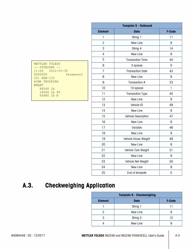
64084448 | 03 | 12/2017 METTLER TOLEDO IND246 and IND246 POWERCELL User's Guide A-3
Template 5 - Outbound
Element Data F-Code
1 String 1 11
2 New Line 9
3 String 4 14
4 New Line 9
5 Transaction Time 44
6 3 spaces 0
7 Transaction Date 43
8 New Line 9
9 Transaction # 23
10 10 spaces 1
11 Transaction Type 45
12 New Line 9
13 Vehicle ID 49
14 New Line 9
15 Vehicle Description 47
16 New Line 9
17 Variable 46
18 New Line 9
19 Vehicle Gross Weight 48
20 New Line 9
21 Vehicle Tare Weight 51
22 New Line 9
23 Vehicle Net Weight 50
24 New Line 9
25 End of template 5
A.3. Checkweighing Application Template 6 - Checkweighing
Element Data F-Code
1 String 1 11
2 New Line 9
3 String 2 12
4 New Line 9
METTLER TOLEDO -- OUTBOUND -- 11:06 2012-03-30 0000009 Permanent ID: ABB-123 ACME TRUCKING WHEAT 84540 lb 18560 lb PT 65980 lb N
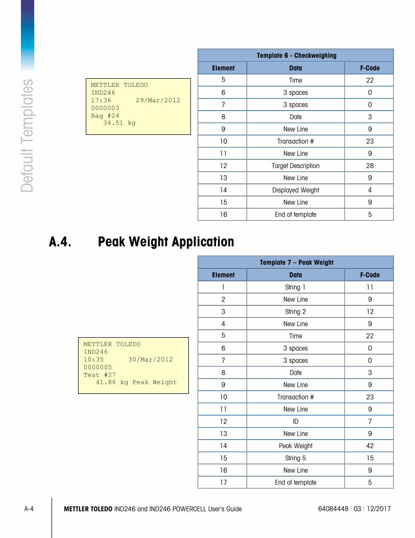
A-4 METTLER TOLEDO IND246 and IND246 POWERCELL User's Guide 64084448 | 03 | 12/2017
Def
ault
Tem
plat
es
Template 6 - Checkweighing
Element Data F-Code
5 Time 22
6 3 spaces 0
7 3 spaces 0
8 Date 3
9 New Line 9
10 Transaction # 23
11 New Line 9
12 Target Description 28
13 New Line 9
14 Displayed Weight 4
15 New Line 9
16 End of template 5
A.4. Peak Weight Application Template 7 – Peak Weight
Element Data F-Code
1 String 1 11
2 New Line 9
3 String 2 12
4 New Line 9
5 Time 22
6 3 spaces 0
7 3 spaces 0
8 Date 3
9 New Line 9
10 Transaction # 23
11 New Line 9
12 ID 7
13 New Line 9
14 Peak Weight 42
15 String 5 15
16 New Line 9
17 End of template 5
METTLER TOLEDO IND246 17:36 29/Mar/2012 0000003 Bag #24 34.51 kg
METTLER TOLEDO IND246 10:35 30/Mar/2012 0000005 Test #27 41.86 kg Peak Weight
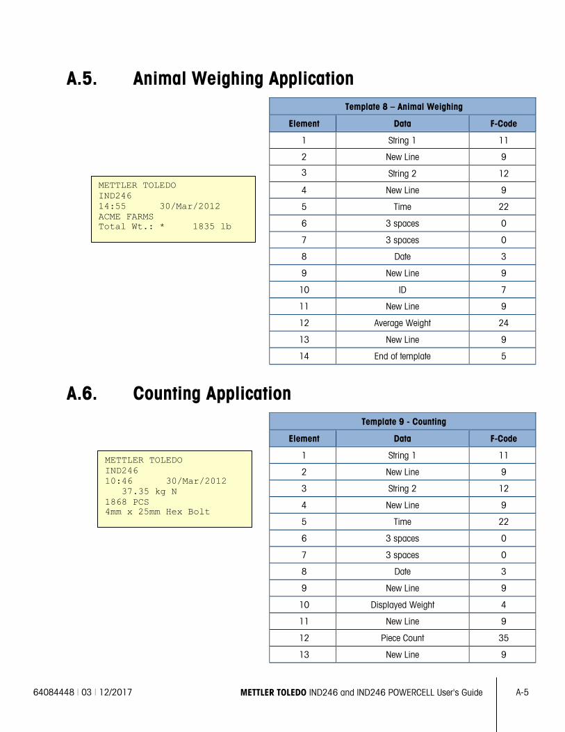
64084448 | 03 | 12/2017 METTLER TOLEDO IND246 and IND246 POWERCELL User's Guide A-5
A.5. Animal Weighing Application Template 8 – Animal Weighing
Element Data F-Code
1 String 1 11
2 New Line 9
3 String 2 12
4 New Line 9
5 Time 22
6 3 spaces 0
7 3 spaces 0
8 Date 3
9 New Line 9
10 ID 7
11 New Line 9
12 Average Weight 24
13 New Line 9
14 End of template 5
A.6. Counting Application Template 9 - Counting
Element Data F-Code
1 String 1 11
2 New Line 9
3 String 2 12
4 New Line 9
5 Time 22
6 3 spaces 0
7 3 spaces 0
8 Date 3
9 New Line 9
10 Displayed Weight 4
11 New Line 9
12 Piece Count 35
13 New Line 9
METTLER TOLEDO IND246 14:55 30/Mar/2012 ACME FARMS Total Wt.: * 1835 lb
METTLER TOLEDO IND246 10:46 30/Mar/2012 37.35 kg N 1868 PCS 4mm x 25mm Hex Bolt
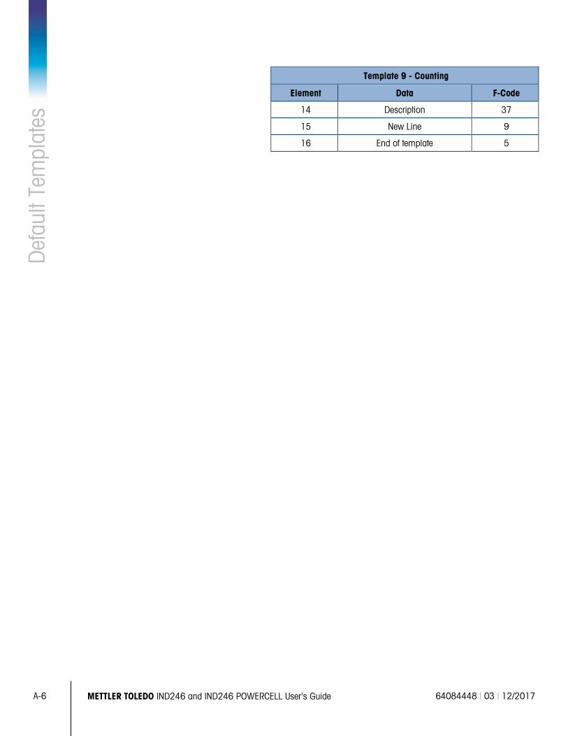
A-6 METTLER TOLEDO IND246 and IND246 POWERCELL User's Guide 64084448 | 03 | 12/2017
Def
ault
Tem
plat
es
Template 9 - Counting
Element Data F-Code
14 Description 37
15 New Line 9
16 End of template 5
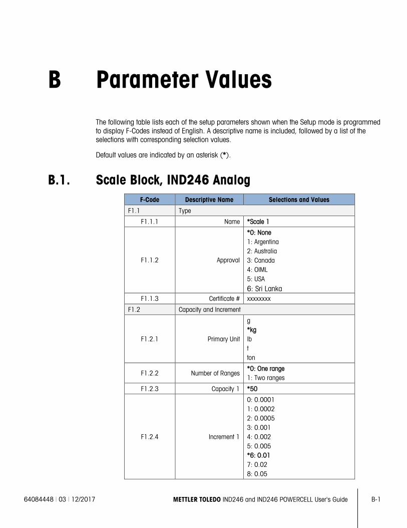
64084448 | 03 | 12/2017 METTLER TOLEDO IND246 and IND246 POWERCELL User's Guide B-1
B Parameter Values The following table lists each of the setup parameters shown when the Setup mode is programmed to display F-Codes instead of English. A descriptive name is included, followed by a list of the selections with corresponding selection values.
Default values are indicated by an asterisk (*).
B.1. Scale Block, IND246 Analog F-Code Descriptive Name Selections and Values
F1.1 Type
F1.1.1 Name *Scale 1
F1.1.2 Approval
*0: None 1: Argentina 2: Australia 3: Canada 4: OIML 5: USA
6: Sri Lanka F1.1.3 Certificate # xxxxxxxx
F1.2 Capacity and Increment
F1.2.1 Primary Unit
g *kg lb t ton
F1.2.2 Number of Ranges *0: One range 1: Two ranges
F1.2.3 Capacity 1 *50
F1.2.4 Increment 1
0: 0.0001 1: 0.0002 2: 0.0005 3: 0.001 4: 0.002 5: 0.005 *6: 0.01 7: 0.02 8: 0.05
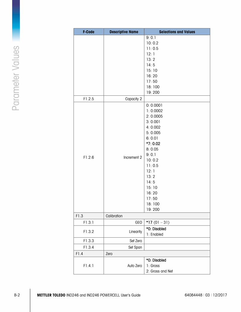
B-2 METTLER TOLEDO IND246 and IND246 POWERCELL User's Guide 64084448 | 03 | 12/2017
Para
met
er V
alue
s
F-Code Descriptive Name Selections and Values 9: 0.1 10: 0.2 11: 0.5 12: 1 13: 2 14: 5 15: 10 16: 20 17: 50 18: 100 19: 200
F1.2.5 Capacity 2
F1.2.6 Increment 2
0: 0.0001 1: 0.0002 2: 0.0005 3: 0.001 4: 0.002 5: 0.005 6: 0.01 *7: 0.02 8: 0.05 9: 0.1 10: 0.2 11: 0.5 12: 1 13: 2 14: 5 15: 10 16: 20 17: 50 18: 100 19: 200
F1.3 Calibration
F1.3.1 GEO *17 (01 – 31)
F1.3.2 Linearity *0: Disabled 1: Enabled
F1.3.3 Set Zero
F1.3.4 Set Span
F1.4 Zero
F1.4.1 Auto Zero *0: Disabled 1: Gross 2: Gross and Net
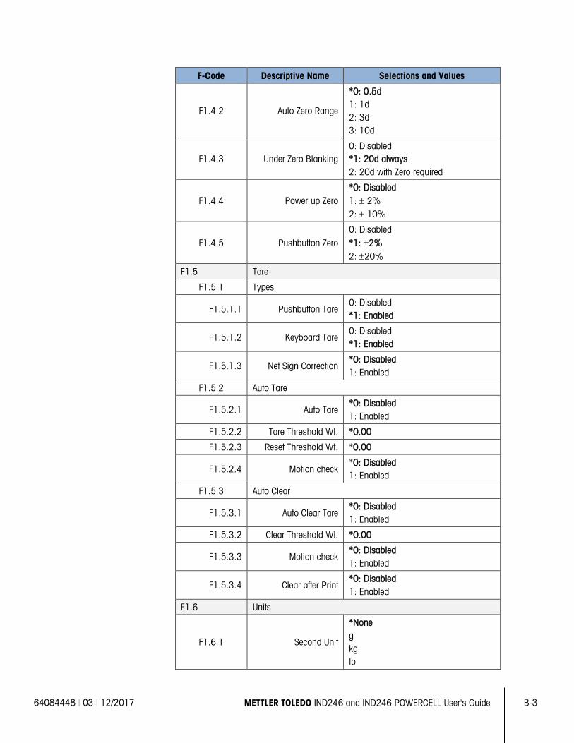
64084448 | 03 | 12/2017 METTLER TOLEDO IND246 and IND246 POWERCELL User's Guide B-3
F-Code Descriptive Name Selections and Values
F1.4.2 Auto Zero Range
*0: 0.5d 1: 1d 2: 3d 3: 10d
F1.4.3 Under Zero Blanking 0: Disabled *1: 20d always 2: 20d with Zero required
F1.4.4 Power up Zero *0: Disabled 1: ± 2% 2: ± 10%
F1.4.5 Pushbutton Zero 0: Disabled *1: ±2% 2: ±20%
F1.5 Tare
F1.5.1 Types
F1.5.1.1 Pushbutton Tare 0: Disabled *1: Enabled
F1.5.1.2 Keyboard Tare 0: Disabled *1: Enabled
F1.5.1.3 Net Sign Correction *0: Disabled 1: Enabled
F1.5.2 Auto Tare
F1.5.2.1 Auto Tare *0: Disabled 1: Enabled
F1.5.2.2 Tare Threshold Wt. *0.00
F1.5.2.3 Reset Threshold Wt. *0.00
F1.5.2.4 Motion check *0: Disabled 1: Enabled
F1.5.3 Auto Clear
F1.5.3.1 Auto Clear Tare *0: Disabled 1: Enabled
F1.5.3.2 Clear Threshold Wt. *0.00
F1.5.3.3 Motion check *0: Disabled 1: Enabled
F1.5.3.4 Clear after Print *0: Disabled 1: Enabled
F1.6 Units
F1.6.1 Second Unit
*None g kg lb
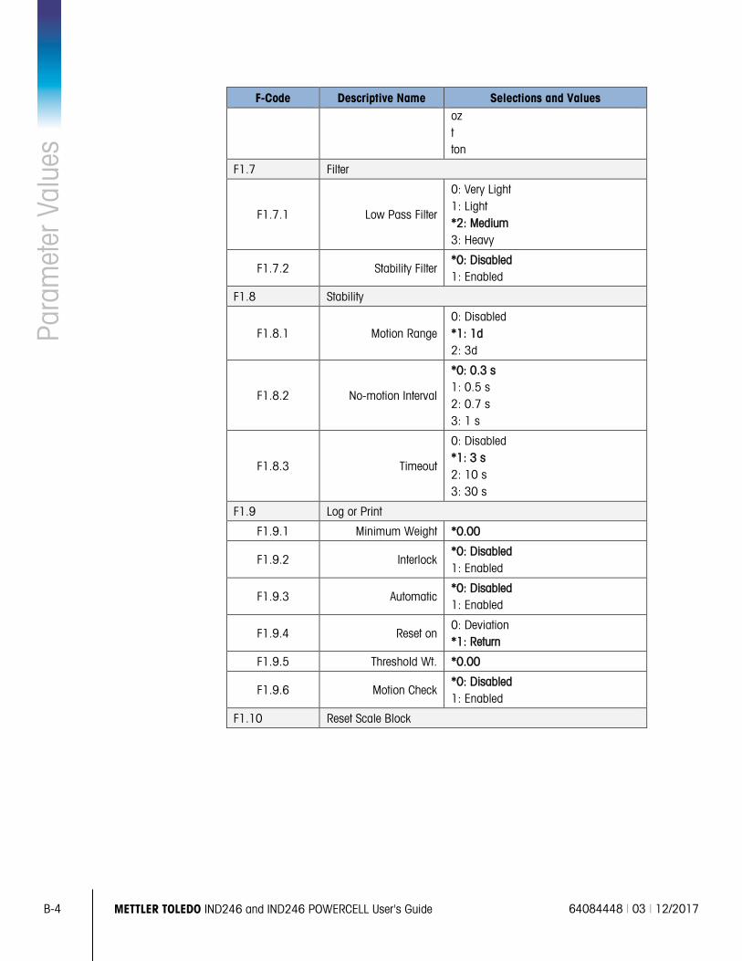
B-4 METTLER TOLEDO IND246 and IND246 POWERCELL User's Guide 64084448 | 03 | 12/2017
Para
met
er V
alue
s
F-Code Descriptive Name Selections and Values oz t ton
F1.7 Filter
F1.7.1 Low Pass Filter
0: Very Light 1: Light *2: Medium 3: Heavy
F1.7.2 Stability Filter *0: Disabled 1: Enabled
F1.8 Stability
F1.8.1 Motion Range 0: Disabled *1: 1d 2: 3d
F1.8.2 No-motion Interval
*0: 0.3 s 1: 0.5 s 2: 0.7 s 3: 1 s
F1.8.3 Timeout
0: Disabled *1: 3 s 2: 10 s 3: 30 s
F1.9 Log or Print
F1.9.1 Minimum Weight *0.00
F1.9.2 Interlock *0: Disabled 1: Enabled
F1.9.3 Automatic *0: Disabled 1: Enabled
F1.9.4 Reset on 0: Deviation *1: Return
F1.9.5 Threshold Wt. *0.00
F1.9.6 Motion Check *0: Disabled 1: Enabled
F1.10 Reset Scale Block
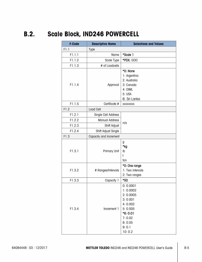
64084448 | 03 | 12/2017 METTLER TOLEDO IND246 and IND246 POWERCELL User's Guide B-5
B.2. Scale Block, IND246 POWERCELL F-Code Descriptive Name Selections and Values
F1.1 Type
F1.1.1 Name *Scale 1
F1.1.2 Scale Type *PDX, GDD
F1.1.3 # of Loadcells
F1.1.4 Approval
*0: None 1: Argentina 2: Australia 3: Canada 4: OIML 5: USA
6. Sri Lanka F1.1.5 Certificate # xxxxxxxx
F1.2 Load Cell
F1.2.1 Single Cell Address
n/a F1.2.2 Manual Address
F1.2.3 Shift Adjust
F1.2.4 Shift Adjust Single
F1.3 Capacity and Increment
F1.3.1 Primary Unit
g *kg lb t ton
F1.3.2 # Ranges/Intervals *0: One range 1: Two intervals 2: Two ranges
F1.3.3 Capacity 1 *50
F1.3.4 Increment 1
0: 0.0001 1: 0.0002 2: 0.0005 3: 0.001 4: 0.002 5: 0.005 *6: 0.01 7: 0.02 8: 0.05 9: 0.1 10: 0.2
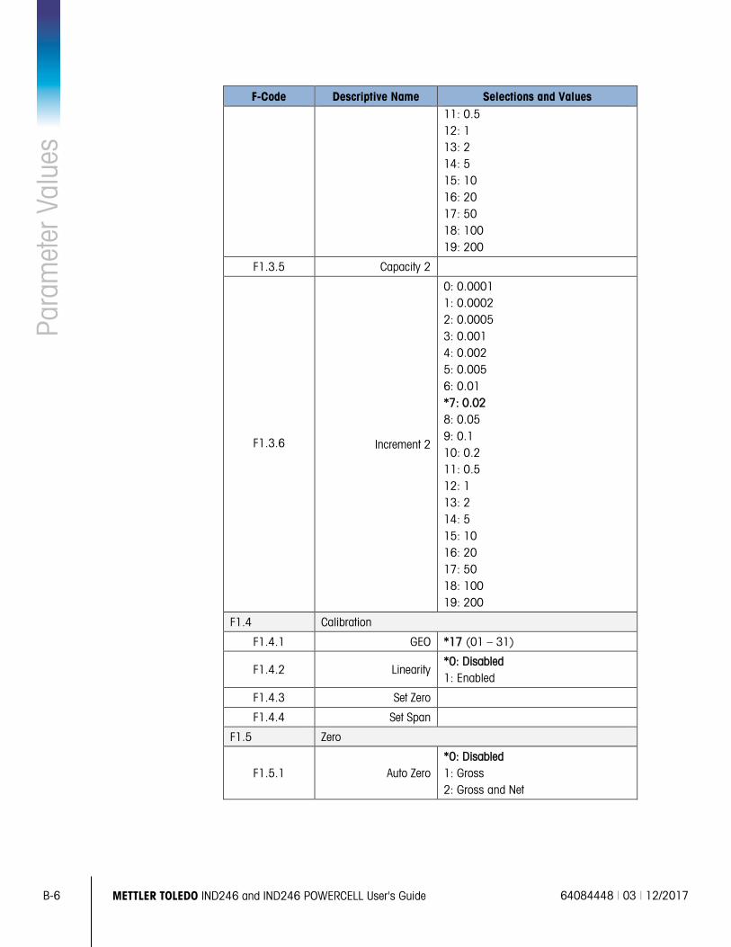
B-6 METTLER TOLEDO IND246 and IND246 POWERCELL User's Guide 64084448 | 03 | 12/2017
Para
met
er V
alue
s
F-Code Descriptive Name Selections and Values 11: 0.5 12: 1 13: 2 14: 5 15: 10 16: 20 17: 50 18: 100 19: 200
F1.3.5 Capacity 2
F1.3.6 Increment 2
0: 0.0001 1: 0.0002 2: 0.0005 3: 0.001 4: 0.002 5: 0.005 6: 0.01 *7: 0.02 8: 0.05 9: 0.1 10: 0.2 11: 0.5 12: 1 13: 2 14: 5 15: 10 16: 20 17: 50 18: 100 19: 200
F1.4 Calibration
F1.4.1 GEO *17 (01 – 31)
F1.4.2 Linearity *0: Disabled 1: Enabled
F1.4.3 Set Zero
F1.4.4 Set Span
F1.5 Zero
F1.5.1 Auto Zero *0: Disabled 1: Gross 2: Gross and Net
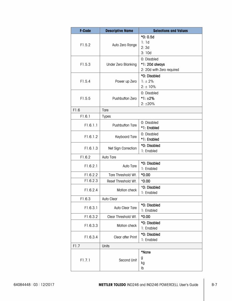
64084448 | 03 | 12/2017 METTLER TOLEDO IND246 and IND246 POWERCELL User's Guide B-7
F-Code Descriptive Name Selections and Values
F1.5.2 Auto Zero Range
*0: 0.5d 1: 1d 2: 3d 3: 10d
F1.5.3 Under Zero Blanking 0: Disabled *1: 20d always 2: 20d with Zero required
F1.5.4 Power up Zero *0: Disabled 1: ± 2% 2: ± 10%
F1.5.5 Pushbutton Zero 0: Disabled *1: ±2% 2: ±20%
F1.6 Tare
F1.6.1 Types
F1.6.1.1 Pushbutton Tare 0: Disabled *1: Enabled
F1.6.1.2 Keyboard Tare 0: Disabled *1: Enabled
F1.6.1.3 Net Sign Correction *0: Disabled 1: Enabled
F1.6.2 Auto Tare
F1.6.2.1 Auto Tare *0: Disabled 1: Enabled
F1.6.2.2 Tare Threshold Wt. *0.00
F1.6.2.3 Reset Threshold Wt. *0.00
F1.6.2.4 Motion check *0: Disabled 1: Enabled
F1.6.3 Auto Clear
F1.6.3.1 Auto Clear Tare *0: Disabled 1: Enabled
F1.6.3.2 Clear Threshold Wt. *0.00
F1.6.3.3 Motion check *0: Disabled 1: Enabled
F1.6.3.4 Clear after Print *0: Disabled 1: Enabled
F1.7 Units
F1.7.1 Second Unit
*None g kg lb
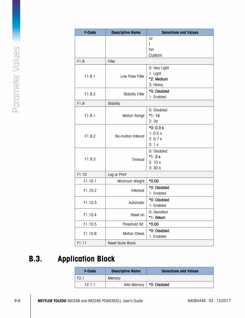
B-8 METTLER TOLEDO IND246 and IND246 POWERCELL User's Guide 64084448 | 03 | 12/2017
Para
met
er V
alue
s
F-Code Descriptive Name Selections and Values oz t ton
Custom F1.8 Filter
F1.8.1 Low Pass Filter
0: Very Light 1: Light *2: Medium 3: Heavy
F1.8.2 Stability Filter *0: Disabled 1: Enabled
F1.9 Stability
F1.9.1 Motion Range 0: Disabled *1: 1d 2: 3d
F1.9.2 No-motion Interval
*0: 0.3 s 1: 0.5 s 2: 0.7 s 3: 1 s
F1.9.3 Timeout
0: Disabled *1: 3 s 2: 10 s 3: 30 s
F1.10 Log or Print
F1.10.1 Minimum Weight *0.00
F1.10.2 Interlock *0: Disabled 1: Enabled
F1.10.3 Automatic *0: Disabled 1: Enabled
F1.10.4 Reset on 0: Deviation *1: Return
F1.10.5 Threshold Wt. *0.00
F1.10.6 Motion Check *0: Disabled 1: Enabled
F1.11 Reset Scale Block
B.3. Application Block F-Code Descriptive Name Selections and Values
F2.1 Memory
F2.1.1 Alibi Memory *0: Disabled
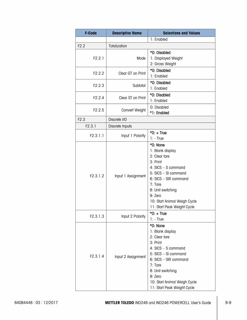
64084448 | 03 | 12/2017 METTLER TOLEDO IND246 and IND246 POWERCELL User's Guide B-9
F-Code Descriptive Name Selections and Values
1: Enabled
F2.2 Totalization
F2.2.1 Mode *0: Disabled 1: Displayed Weight 2: Gross Weight
F2.2.2 Clear GT on Print *0: Disabled 1: Enabled
F2.2.3 Subtotal *0: Disabled 1: Enabled
F2.2.4 Clear ST on Print *0: Disabled 1: Enabled
F2.2.5 Convert Weight 0: Disabled *1: Enabled
F2.3 Discrete I/O
F2.3.1 Discrete Inputs
F2.3.1.1 Input 1 Polarity *0: + True 1: - True
F2.3.1.2 Input 1 Assignment
*0: None 1: Blank display 2: Clear tare 3: Print 4: SICS – S command 5: SICS – SI command 6: SICS – SIR command 7: Tare 8: Unit switching 9: Zero 10: Start Animal Weigh Cycle 11: Start Peak Weight Cycle
F2.3.1.3 Input 2 Polarity *0: + True 1: - True
F2.3.1.4 Input 2 Assignment
*0: None 1: Blank display 2: Clear tare 3: Print 4: SICS – S command 5: SICS – SI command 6: SICS – SIR command 7: Tare 8: Unit switching 9: Zero 10: Start Animal Weigh Cycle 11: Start Peak Weight Cycle
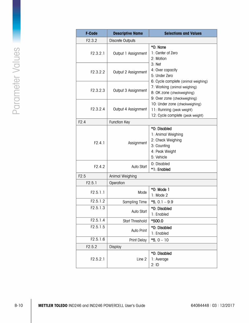
B-10 METTLER TOLEDO IND246 and IND246 POWERCELL User's Guide 64084448 | 03 | 12/2017
Para
met
er V
alue
s
F-Code Descriptive Name Selections and Values
F2.3.2 Discrete Outputs
F2.3.2.1 Output 1 Assignment
*0: None 1: Center of Zero 2: Motion 3: Net 4: Over capacity 5: Under Zero 6: Cycle complete (animal weighing) 7: Working (animal weighing) 8: OK zone (checkweighing) 9: Over zone (checkweighing) 10: Under zone (checkweighing) 11: Running (peak weight) 12: Cycle complete (peak weight)
F2.3.2.2 Output 2 Assignment
F2.3.2.3 Output 3 Assignment
F2.3.2.4 Output 4 Assignment
F2.4 Function Key
F2.4.1 Assignment
*0: Disabled 1: Animal Weighing 2: Check Weighing 3: Counting 4: Peak Weight 5: Vehicle
F2.4.2 Auto Start 0: Disabled *1: Enabled
F2.5 Animal Weighing
F2.5.1 Operation
F2.5.1.1 Mode *0: Mode 1 1: Mode 2
F2.5.1.2 Sampling Time *5, 0.1 – 9.9 F2.5.1.3
Auto Start *0: Disabled 1: Enabled
F2.5.1.4 Start Threshold *500.0 F2.5.1.5
Auto Print *0: Disabled 1: Enabled
F2.5.1.6 Print Delay *5, 0 – 10
F2.5.2 Display
F2.5.2.1 Line 2 *0: Disabled 1: Average 2: ID
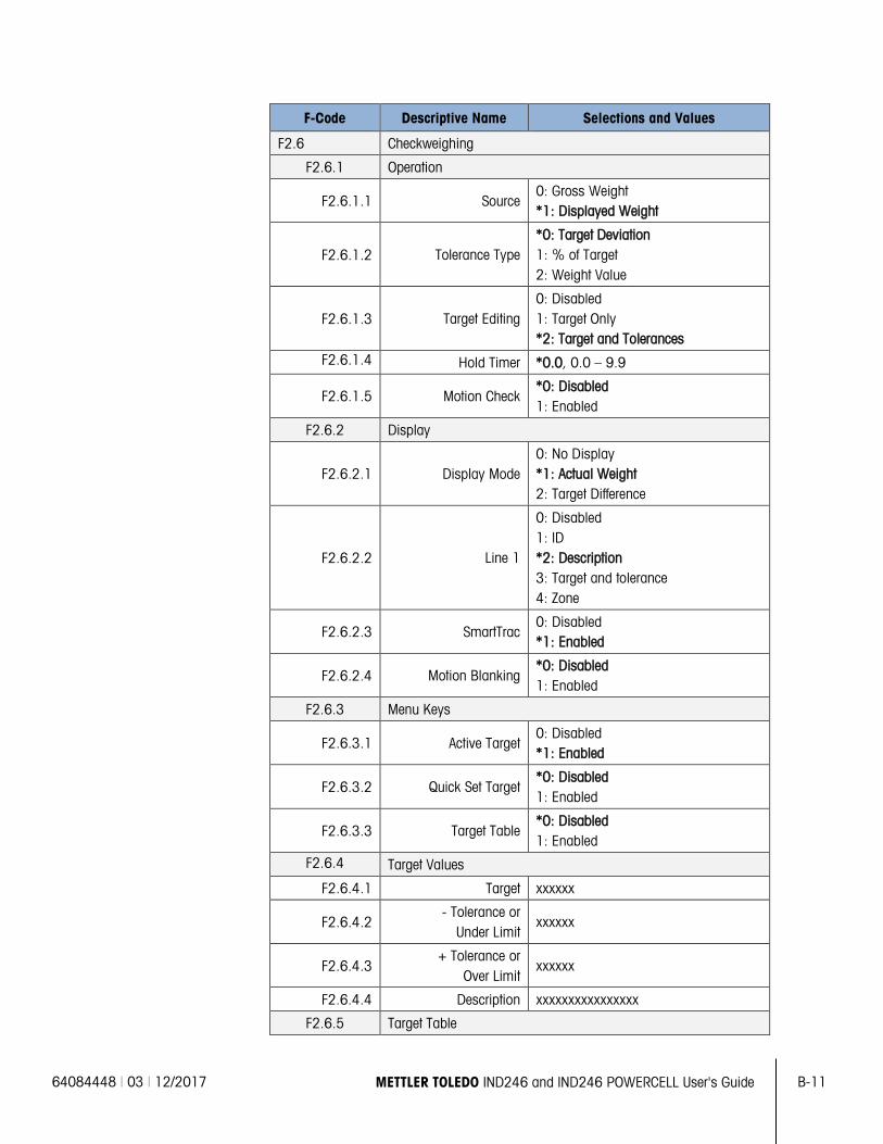
64084448 | 03 | 12/2017 METTLER TOLEDO IND246 and IND246 POWERCELL User's Guide B-11
F-Code Descriptive Name Selections and Values
F2.6 Checkweighing
F2.6.1 Operation
F2.6.1.1 Source 0: Gross Weight *1: Displayed Weight
F2.6.1.2 Tolerance Type *0: Target Deviation 1: % of Target 2: Weight Value
F2.6.1.3 Target Editing 0: Disabled 1: Target Only *2: Target and Tolerances
F2.6.1.4 Hold Timer *0.0, 0.0 – 9.9
F2.6.1.5 Motion Check *0: Disabled 1: Enabled
F2.6.2 Display
F2.6.2.1 Display Mode 0: No Display *1: Actual Weight 2: Target Difference
F2.6.2.2 Line 1
0: Disabled 1: ID *2: Description 3: Target and tolerance 4: Zone
F2.6.2.3 SmartTrac 0: Disabled *1: Enabled
F2.6.2.4 Motion Blanking *0: Disabled 1: Enabled
F2.6.3 Menu Keys
F2.6.3.1 Active Target 0: Disabled *1: Enabled
F2.6.3.2 Quick Set Target *0: Disabled 1: Enabled
F2.6.3.3 Target Table *0: Disabled 1: Enabled
F2.6.4 Target Values
F2.6.4.1 Target xxxxxx
F2.6.4.2 - Tolerance or
Under Limit xxxxxx
F2.6.4.3 + Tolerance or
Over Limit xxxxxx
F2.6.4.4 Description xxxxxxxxxxxxxxxx
F2.6.5 Target Table
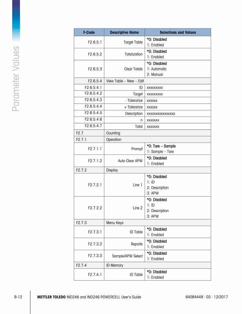
B-12 METTLER TOLEDO IND246 and IND246 POWERCELL User's Guide 64084448 | 03 | 12/2017
Para
met
er V
alue
s
F-Code Descriptive Name Selections and Values
F2.6.5.1 Target Table *0: Disabled 1: Enabled
F2.6.5.2 Totalization *0: Disabled 1: Enabled
F2.6.5.3 Clear Totals *0: Disabled 1: Automatic 2: Manual
F2.6.5.4 View Table – New – Edit
F2.6.5.4.1 ID xxxxxxxxx F2.6.5.4.2 Target xxxxxxxxx F2.6.5.4.3 - Tolerance xxxxxx F2.6.5.4.4 + Tolerance xxxxxx F2.6.5.4.5 Description xxxxxxxxxxxxxxxx F2.6.5.4.6 n xxxxxxx F2.6.5.4.7 Total xxxxxxx
F2.7 Counting
F2.7.1 Operation
F2.7.1.1 Prompt *0: Tare – Sample 1: Sample – Tare
F2.7.1.2 Auto Clear APW *0: Disabled 1: Enabled
F2.7.2 Display
F2.7.2.1 Line 1
*0: Disabled 1: ID 2: Description 3: APW
F2.7.2.2 Line 2
*0: Disabled 1: ID 2: Description 3: APW
F2.7.3 Menu Keys
F2.7.3.1 ID Table *0: Disabled 1: Enabled
F2.7.3.2 Reports *0: Disabled 1: Enabled
F2.7.3.3 Sample/APW Select *0: Disabled 1: Enabled
F2.7.4 ID Memory
F2.7.4.1 ID Table *0: Disabled 1: Enabled
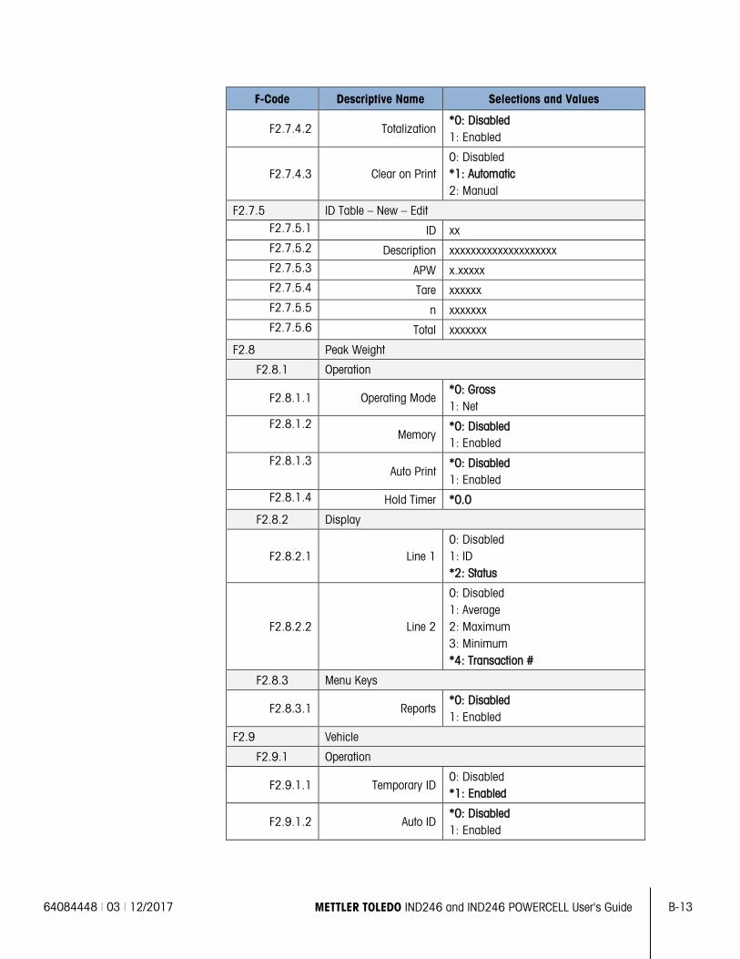
64084448 | 03 | 12/2017 METTLER TOLEDO IND246 and IND246 POWERCELL User's Guide B-13
F-Code Descriptive Name Selections and Values
F2.7.4.2 Totalization *0: Disabled 1: Enabled
F2.7.4.3 Clear on Print 0: Disabled *1: Automatic 2: Manual
F2.7.5 ID Table – New – Edit F2.7.5.1 ID xx F2.7.5.2 Description xxxxxxxxxxxxxxxxxxxx F2.7.5.3 APW x.xxxxx F2.7.5.4 Tare xxxxxx F2.7.5.5 n xxxxxxx F2.7.5.6 Total xxxxxxx
F2.8 Peak Weight
F2.8.1 Operation
F2.8.1.1 Operating Mode *0: Gross 1: Net
F2.8.1.2 Memory
*0: Disabled 1: Enabled
F2.8.1.3 Auto Print
*0: Disabled 1: Enabled
F2.8.1.4 Hold Timer *0.0
F2.8.2 Display
F2.8.2.1 Line 1 0: Disabled 1: ID *2: Status
F2.8.2.2 Line 2
0: Disabled 1: Average 2: Maximum 3: Minimum *4: Transaction #
F2.8.3 Menu Keys
F2.8.3.1 Reports *0: Disabled 1: Enabled
F2.9 Vehicle
F2.9.1 Operation
F2.9.1.1 Temporary ID 0: Disabled *1: Enabled
F2.9.1.2 Auto ID *0: Disabled 1: Enabled
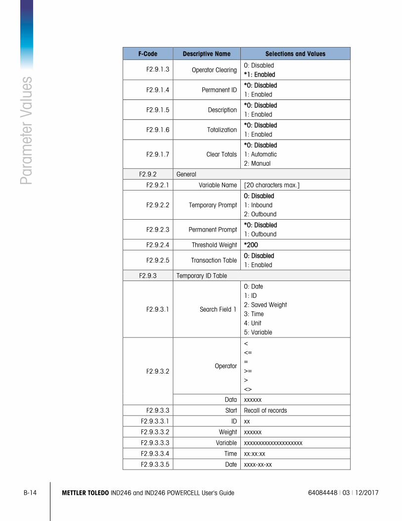
B-14 METTLER TOLEDO IND246 and IND246 POWERCELL User's Guide 64084448 | 03 | 12/2017
Para
met
er V
alue
s
F-Code Descriptive Name Selections and Values
F2.9.1.3 Operator Clearing 0: Disabled *1: Enabled
F2.9.1.4 Permanent ID *0: Disabled 1: Enabled
F2.9.1.5 Description *0: Disabled 1: Enabled
F2.9.1.6 Totalization *0: Disabled 1: Enabled
F2.9.1.7 Clear Totals *0: Disabled 1: Automatic 2: Manual
F2.9.2 General
F2.9.2.1 Variable Name [20 characters max.]
F2.9.2.2 Temporary Prompt 0: Disabled 1: Inbound 2: Outbound
F2.9.2.3 Permanent Prompt *0: Disabled 1: Outbound
F2.9.2.4 Threshold Weight *200
F2.9.2.5 Transaction Table 0: Disabled 1: Enabled
F2.9.3 Temporary ID Table
F2.9.3.1 Search Field 1
0: Date 1: ID 2: Saved Weight 3: Time 4: Unit 5: Variable
F2.9.3.2 Operator
< <= = >= > <>
Data xxxxxx
F2.9.3.3 Start Recall of records
F2.9.3.3.1 ID xx
F2.9.3.3.2 Weight xxxxxx
F2.9.3.3.3 Variable xxxxxxxxxxxxxxxxxxxx
F2.9.3.3.4 Time xx:xx:xx
F2.9.3.3.5 Date xxxx-xx-xx
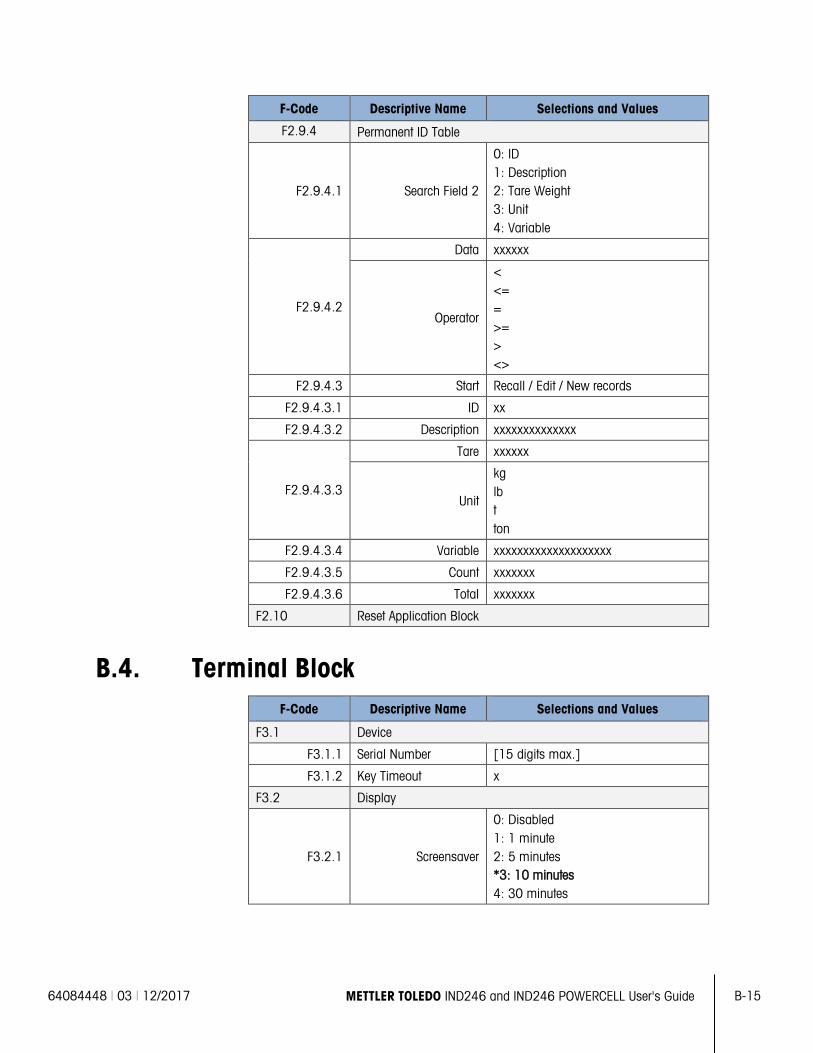
64084448 | 03 | 12/2017 METTLER TOLEDO IND246 and IND246 POWERCELL User's Guide B-15
F-Code Descriptive Name Selections and Values
F2.9.4 Permanent ID Table
F2.9.4.1 Search Field 2
0: ID 1: Description 2: Tare Weight 3: Unit 4: Variable
F2.9.4.2
Data xxxxxx
Operator
< <= = >= > <>
F2.9.4.3 Start Recall / Edit / New records
F2.9.4.3.1 ID xx
F2.9.4.3.2 Description xxxxxxxxxxxxxx
F2.9.4.3.3
Tare xxxxxx
Unit
kg lb t ton
F2.9.4.3.4 Variable xxxxxxxxxxxxxxxxxxxx
F2.9.4.3.5 Count xxxxxxx
F2.9.4.3.6 Total xxxxxxx
F2.10 Reset Application Block
B.4. Terminal Block F-Code Descriptive Name Selections and Values
F3.1 Device
F3.1.1 Serial Number [15 digits max.]
F3.1.2 Key Timeout x
F3.2 Display
F3.2.1 Screensaver
0: Disabled 1: 1 minute 2: 5 minutes *3: 10 minutes 4: 30 minutes
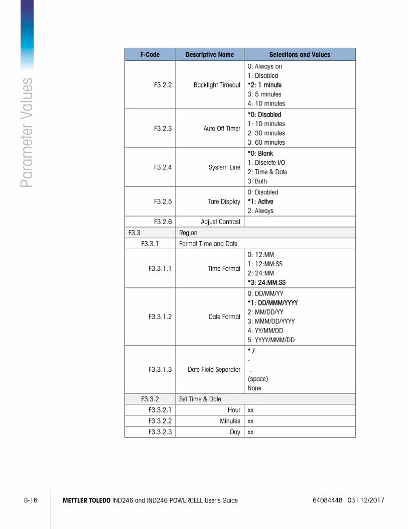
B-16 METTLER TOLEDO IND246 and IND246 POWERCELL User's Guide 64084448 | 03 | 12/2017
Para
met
er V
alue
s
F-Code Descriptive Name Selections and Values
F3.2.2 Backlight Timeout
0: Always on 1: Disabled *2: 1 minute 3: 5 minutes 4: 10 minutes
F3.2.3 Auto Off Timer
*0: Disabled 1: 10 minutes 2: 30 minutes 3: 60 minutes
F3.2.4 System Line
*0: Blank 1: Discrete I/O 2: Time & Date 3: Both
F3.2.5 Tare Display 0: Disabled *1: Active 2: Always
F3.2.6 Adjust Contrast
F3.3 Region
F3.3.1 Format Time and Date
F3.3.1.1 Time Format
0: 12:MM 1: 12:MM:SS 2: 24:MM *3: 24:MM:SS
F3.3.1.2 Date Format
0: DD/MM/YY *1: DD/MMM/YYYY 2: MM/DD/YY 3: MMM/DD/YYYY 4: YY/MM/DD 5: YYYY/MMM/DD
F3.3.1.3 Date Field Separator
* / - . (space) None
F3.3.2 Set Time & Date
F3.3.2.1 Hour xx
F3.3.2.2 Minutes xx
F3.3.2.3 Day xx
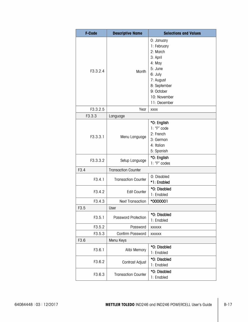
64084448 | 03 | 12/2017 METTLER TOLEDO IND246 and IND246 POWERCELL User's Guide B-17
F-Code Descriptive Name Selections and Values
F3.3.2.4 Month
0: January 1: February 2: March 3: April 4: May 5: June 6: July 7: August 8: September 9: October 10: November 11: December
F3.3.2.5 Year xxxx
F3.3.3 Language
F3.3.3.1 Menu Language
*0: English 1: “F” code 2: French 3: German 4: Italian 5: Spanish
F3.3.3.2 Setup Language *0: English 1: “F” codes
F3.4 Transaction Counter
F3.4.1 Transaction Counter 0: Disabled *1: Enabled
F3.4.2 Edit Counter *0: Disabled 1: Enabled
F3.4.3 Next Transaction *0000001
F3.5 User
F3.5.1 Password Protection *0: Disabled 1: Enabled
F3.5.2 Password xxxxxx
F3.5.3 Confirm Password xxxxxx
F3.6 Menu Keys
F3.6.1 Alibi Memory *0: Disabled 1: Enabled
F3.6.2 Contrast Adjust *0: Disabled 1: Enabled
F3.6.3 Transaction Counter *0: Disabled 1: Enabled
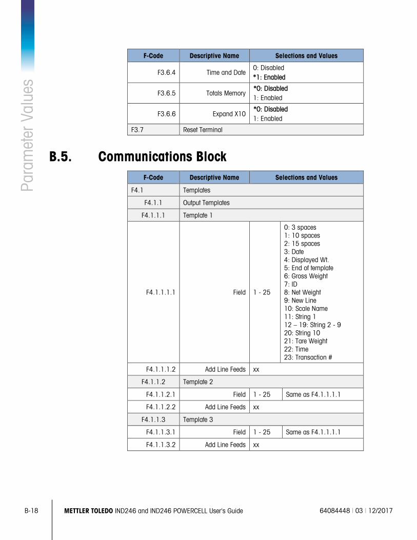
B-18 METTLER TOLEDO IND246 and IND246 POWERCELL User's Guide 64084448 | 03 | 12/2017
Para
met
er V
alue
s
F-Code Descriptive Name Selections and Values
F3.6.4 Time and Date 0: Disabled *1: Enabled
F3.6.5 Totals Memory *0: Disabled 1: Enabled
F3.6.6 Expand X10 *0: Disabled 1: Enabled
F3.7 Reset Terminal
B.5. Communications Block F-Code Descriptive Name Selections and Values
F4.1 Templates
F4.1.1 Output Templates
F4.1.1.1 Template 1
F4.1.1.1.1 Field 1 - 25
0: 3 spaces 1: 10 spaces 2: 15 spaces 3: Date 4: Displayed Wt. 5: End of template 6: Gross Weight 7: ID 8: Net Weight 9: New Line 10: Scale Name 11: String 1 12 – 19: String 2 - 9 20: String 10 21: Tare Weight 22: Time 23: Transaction #
F4.1.1.1.2 Add Line Feeds xx
F4.1.1.2 Template 2
F4.1.1.2.1 Field 1 - 25 Same as F4.1.1.1.1
F4.1.1.2.2 Add Line Feeds xx
F4.1.1.3 Template 3
F4.1.1.3.1 Field 1 - 25 Same as F4.1.1.1.1
F4.1.1.3.2 Add Line Feeds xx

64084448 | 03 | 12/2017 METTLER TOLEDO IND246 and IND246 POWERCELL User's Guide B-19
F-Code Descriptive Name Selections and Values
F4.1.1.4 Template 4 (Vehicle Inbound)
F4.1.1.4.1 Field 1 - 25
All of F4.1.1.1.1, plus 43: Transaction Date 44: Transaction Time 45: Transaction Type 46: Variable 47: Vehicle Description 48: Vehicle Gross Weight 49: Vehicle ID 50: Vehicle Net Weight 51: Vehicle Tare Weight
F4.1.1.4.2 Add Line Feeds xx
F4.1.1.5 Template 5 (Vehicle Outbound)
F4.1.1.5.1 Field 1 - 25
All of F4.1.1.1.1, plus 43: Transaction Date 44: Transaction Time 45: Transaction Type 46: Variable 47: Vehicle Description 48: Vehicle Gross Weight 49: Vehicle ID 50: Vehicle Net Weight 51: Vehicle Tare Weight
F4.1.1.5.2 Add Line Feeds xx
F4.1.1.6 Template 6 (Checkweighing)
F4.1.1.6.1 Field 1 - 25
All of F4.1.1.1.1, plus 27: n 28: Target Description 29: Target ID 30: Target Weight 31: Target & Tolerances 32: Total 33: Zone
F4.1.1.6.2 Add Line Feeds xx
F4.1.1.7 Template 7 (Peak Force Measurement)
F4.1.1.7.1 1 - 25
All of F4.1.1.1.1, plus 38: # of Cycles 39: Average Weight 40: Maximum Weight 41: Minimum Weight 42: Peak Weight
F4.1.1.7.2 Add Line Feeds xx
F4.1.1.8 Template 8 (Animal Weighing)
F4.1.1.8.1 Field 1 - 25
All of F4.1.1.1.1, plus 24: Average Weight 25: # of Animals 26: Average per Animal
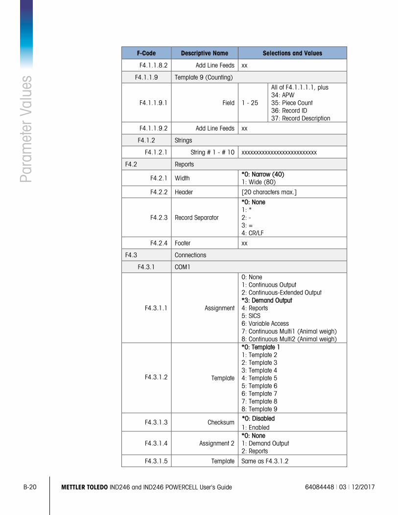
B-20 METTLER TOLEDO IND246 and IND246 POWERCELL User's Guide 64084448 | 03 | 12/2017
Para
met
er V
alue
s
F-Code Descriptive Name Selections and Values
F4.1.1.8.2 Add Line Feeds xx
F4.1.1.9 Template 9 (Counting)
F4.1.1.9.1 Field 1 - 25
All of F4.1.1.1.1, plus 34: APW 35: Piece Count 36: Record ID 37: Record Description
F4.1.1.9.2 Add Line Feeds xx
F4.1.2 Strings
F4.1.2.1 String # 1 - # 10 xxxxxxxxxxxxxxxxxxxxxxxxxx
F4.2 Reports
F4.2.1 Width *0: Narrow (40) 1: Wide (80)
F4.2.2 Header [20 characters max.]
F4.2.3 Record Separator
*0: None 1: * 2: - 3: = 4: CR/LF
F4.2.4 Footer xx
F4.3 Connections
F4.3.1 COM1
F4.3.1.1 Assignment
0: None 1: Continuous Output 2: Continuous-Extended Output *3: Demand Output 4: Reports 5: SICS 6: Variable Access 7: Continuous Multi1 (Animal weigh) 8: Continuous Multi2 (Animal weigh)
F4.3.1.2 Template
*0: Template 1 1: Template 2 2: Template 3 3: Template 4 4: Template 5 5: Template 6 6: Template 7 7: Template 8 8: Template 9
F4.3.1.3 Checksum *0: Disabled 1: Enabled
F4.3.1.4 Assignment 2 *0: None 1: Demand Output 2: Reports
F4.3.1.5 Template Same as F4.3.1.2
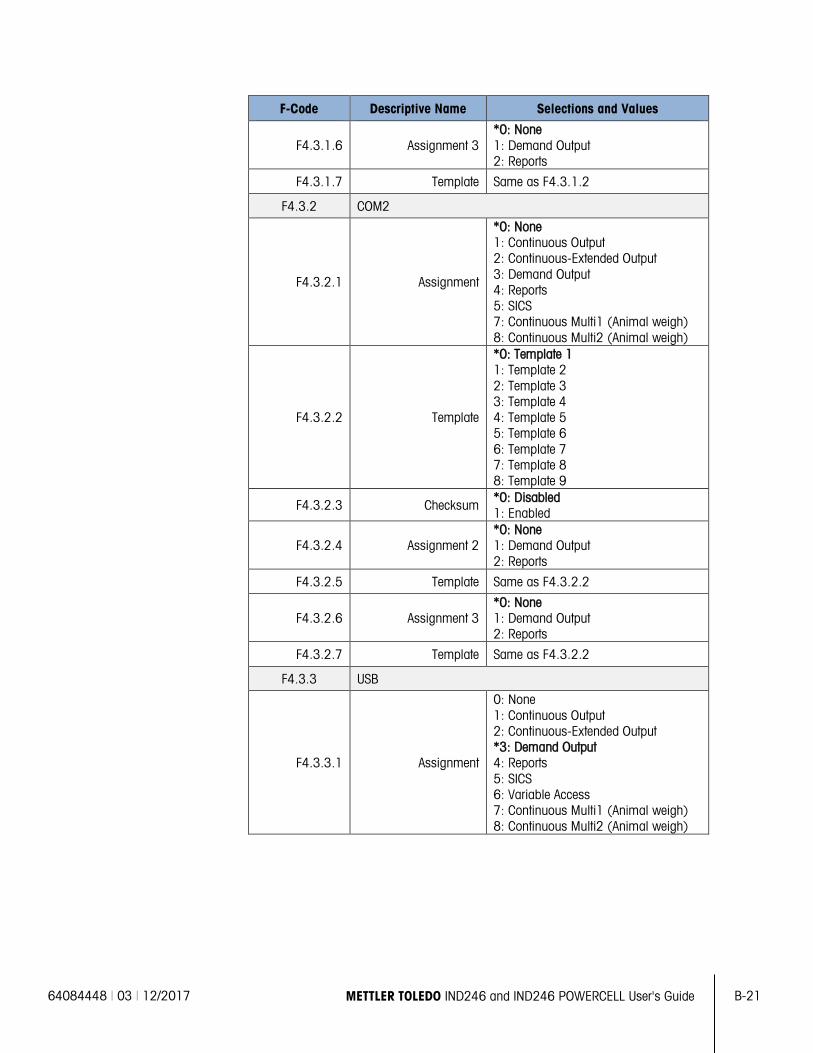
64084448 | 03 | 12/2017 METTLER TOLEDO IND246 and IND246 POWERCELL User's Guide B-21
F-Code Descriptive Name Selections and Values
F4.3.1.6 Assignment 3 *0: None 1: Demand Output 2: Reports
F4.3.1.7 Template Same as F4.3.1.2
F4.3.2 COM2
F4.3.2.1 Assignment
*0: None 1: Continuous Output 2: Continuous-Extended Output 3: Demand Output 4: Reports 5: SICS 7: Continuous Multi1 (Animal weigh) 8: Continuous Multi2 (Animal weigh)
F4.3.2.2 Template
*0: Template 1 1: Template 2 2: Template 3 3: Template 4 4: Template 5 5: Template 6 6: Template 7 7: Template 8 8: Template 9
F4.3.2.3 Checksum *0: Disabled 1: Enabled
F4.3.2.4 Assignment 2 *0: None 1: Demand Output 2: Reports
F4.3.2.5 Template Same as F4.3.2.2
F4.3.2.6 Assignment 3 *0: None 1: Demand Output 2: Reports
F4.3.2.7 Template Same as F4.3.2.2
F4.3.3 USB
F4.3.3.1 Assignment
0: None 1: Continuous Output 2: Continuous-Extended Output *3: Demand Output 4: Reports 5: SICS 6: Variable Access 7: Continuous Multi1 (Animal weigh) 8: Continuous Multi2 (Animal weigh)
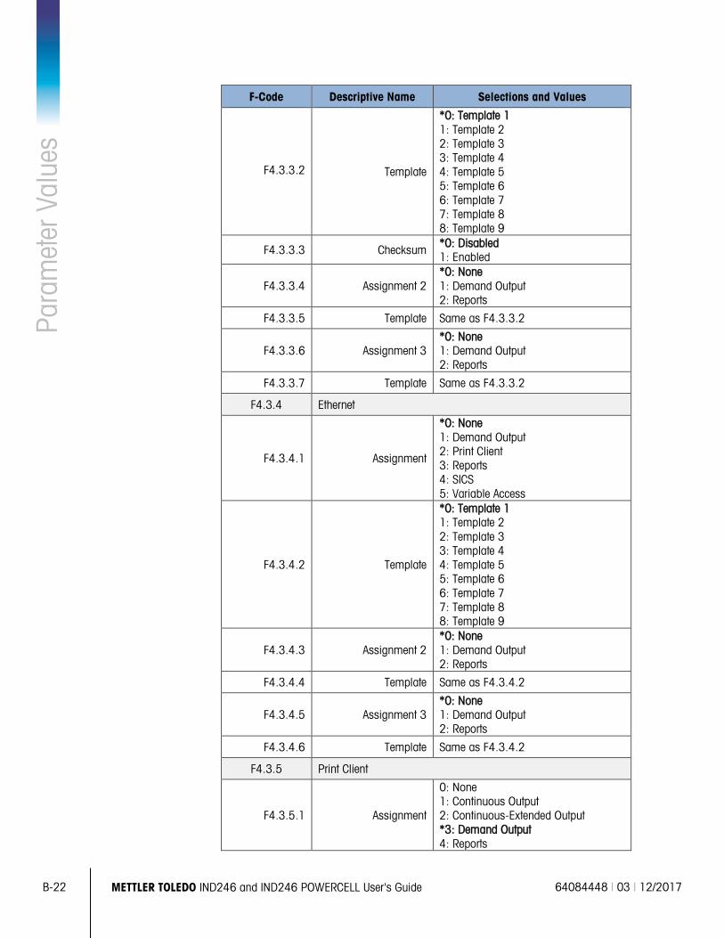
B-22 METTLER TOLEDO IND246 and IND246 POWERCELL User's Guide 64084448 | 03 | 12/2017
Para
met
er V
alue
s
F-Code Descriptive Name Selections and Values
F4.3.3.2 Template
*0: Template 1 1: Template 2 2: Template 3 3: Template 4 4: Template 5 5: Template 6 6: Template 7 7: Template 8 8: Template 9
F4.3.3.3 Checksum *0: Disabled 1: Enabled
F4.3.3.4 Assignment 2 *0: None 1: Demand Output 2: Reports
F4.3.3.5 Template Same as F4.3.3.2
F4.3.3.6 Assignment 3 *0: None 1: Demand Output 2: Reports
F4.3.3.7 Template Same as F4.3.3.2
F4.3.4 Ethernet
F4.3.4.1 Assignment
*0: None 1: Demand Output 2: Print Client 3: Reports 4: SICS 5: Variable Access
F4.3.4.2 Template
*0: Template 1 1: Template 2 2: Template 3 3: Template 4 4: Template 5 5: Template 6 6: Template 7 7: Template 8 8: Template 9
F4.3.4.3 Assignment 2 *0: None 1: Demand Output 2: Reports
F4.3.4.4 Template Same as F4.3.4.2
F4.3.4.5 Assignment 3 *0: None 1: Demand Output 2: Reports
F4.3.4.6 Template Same as F4.3.4.2
F4.3.5 Print Client
F4.3.5.1 Assignment
0: None 1: Continuous Output 2: Continuous-Extended Output *3: Demand Output 4: Reports
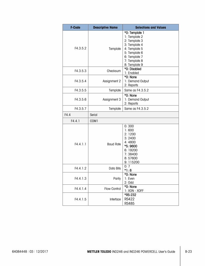
64084448 | 03 | 12/2017 METTLER TOLEDO IND246 and IND246 POWERCELL User's Guide B-23
F-Code Descriptive Name Selections and Values
F4.3.5.2 Template
*0: Template 1 1: Template 2 2: Template 3 3: Template 4 4: Template 5 5: Template 6 6: Template 7 7: Template 8 8: Template 9
F4.3.5.3 Checksum *0: Disabled 1: Enabled
F4.3.5.4 Assignment 2 *0: None 1: Demand Output 2: Reports
F4.3.5.5 Template Same as F4.3.5.2
F4.3.5.6 Assignment 3 *0: None 1: Demand Output 2: Reports
F4.3.5.7 Template Same as F4.3.5.2
F4.4 Serial
F4.4.1 COM1
F4.4.1.1 Baud Rate
0: 300 1: 600 2: 1200 3: 2400 4: 4800 *5: 9600 6: 19200 7: 38400 8: 57600 9: 115200
F4.4.1.2 Data Bits 0: 7 *1: 8
F4.4.1.3 Parity *0: None 1: Even 2: Odd
F4.4.1.4 Flow Control *0: None 1: XON - XOFF
F4.4.1.5 Interface *RS-232 RS422 RS485
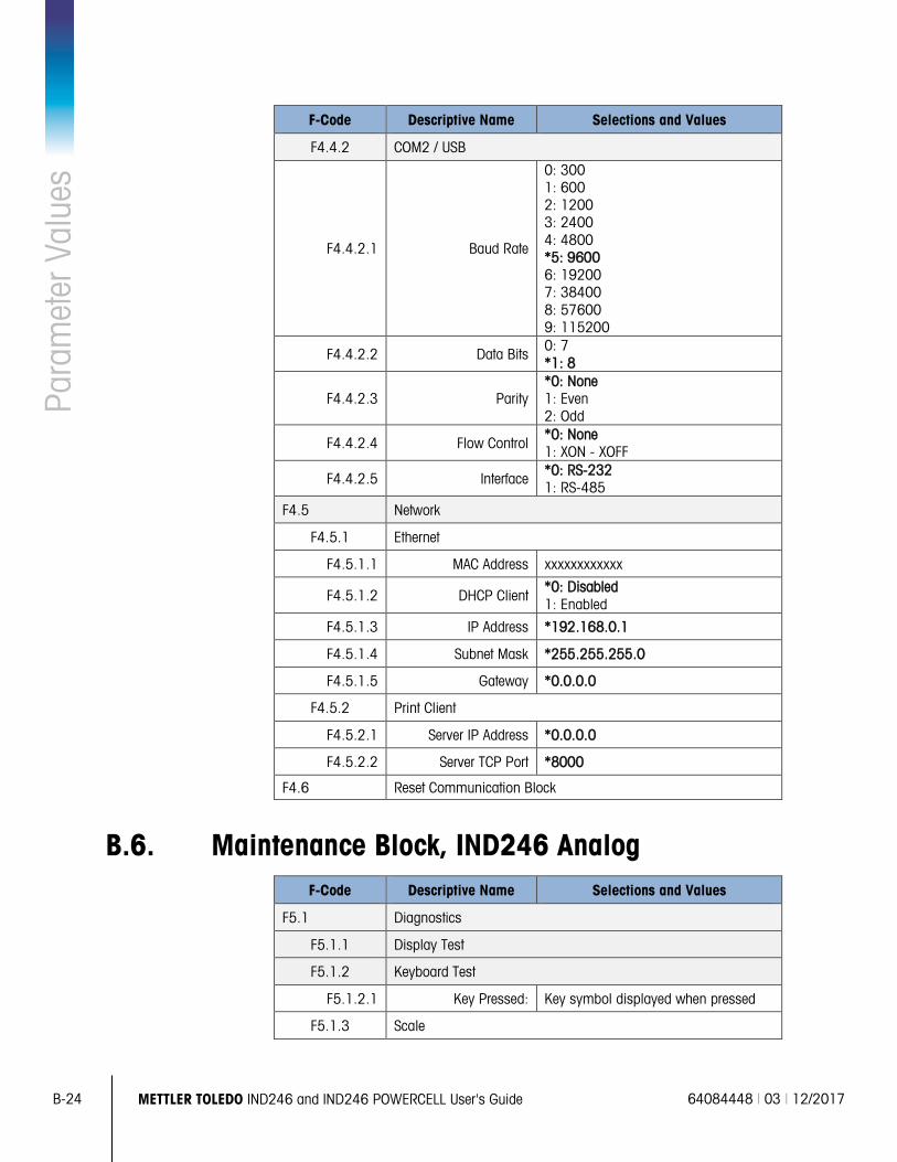
B-24 METTLER TOLEDO IND246 and IND246 POWERCELL User's Guide 64084448 | 03 | 12/2017
Para
met
er V
alue
s
F-Code Descriptive Name Selections and Values
F4.4.2 COM2 / USB
F4.4.2.1 Baud Rate
0: 300 1: 600 2: 1200 3: 2400 4: 4800 *5: 9600 6: 19200 7: 38400 8: 57600 9: 115200
F4.4.2.2 Data Bits 0: 7 *1: 8
F4.4.2.3 Parity *0: None 1: Even 2: Odd
F4.4.2.4 Flow Control *0: None 1: XON - XOFF
F4.4.2.5 Interface *0: RS-232 1: RS-485
F4.5 Network
F4.5.1 Ethernet
F4.5.1.1 MAC Address xxxxxxxxxxxx
F4.5.1.2 DHCP Client *0: Disabled 1: Enabled
F4.5.1.3 IP Address *192.168.0.1
F4.5.1.4 Subnet Mask *255.255.255.0
F4.5.1.5 Gateway *0.0.0.0
F4.5.2 Print Client
F4.5.2.1 Server IP Address *0.0.0.0
F4.5.2.2 Server TCP Port *8000
F4.6 Reset Communication Block
B.6. Maintenance Block, IND246 Analog F-Code Descriptive Name Selections and Values
F5.1 Diagnostics
F5.1.1 Display Test
F5.1.2 Keyboard Test
F5.1.2.1 Key Pressed: Key symbol displayed when pressed
F5.1.3 Scale
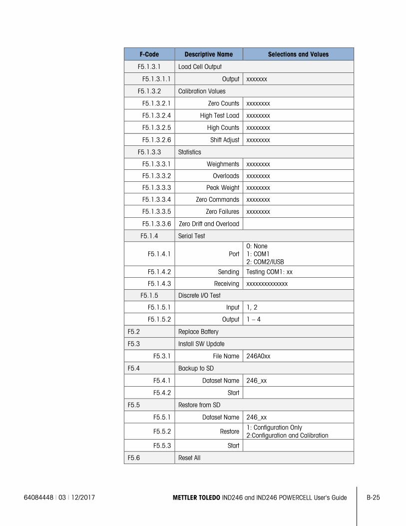
64084448 | 03 | 12/2017 METTLER TOLEDO IND246 and IND246 POWERCELL User's Guide B-25
F-Code Descriptive Name Selections and Values
F5.1.3.1 Load Cell Output
F5.1.3.1.1 Output xxxxxxx
F5.1.3.2 Calibration Values
F5.1.3.2.1 Zero Counts xxxxxxxx
F5.1.3.2.4 High Test Load xxxxxxxx
F5.1.3.2.5 High Counts xxxxxxxx
F5.1.3.2.6 Shift Adjust xxxxxxxx
F5.1.3.3 Statistics
F5.1.3.3.1 Weighments xxxxxxxx
F5.1.3.3.2 Overloads xxxxxxxx
F5.1.3.3.3 Peak Weight xxxxxxxx
F5.1.3.3.4 Zero Commands xxxxxxxx
F5.1.3.3.5 Zero Failures xxxxxxxx
F5.1.3.3.6 Zero Drift and Overload
F5.1.4 Serial Test
F5.1.4.1 Port 0: None 1: COM1 2: COM2/lUSB
F5.1.4.2 Sending Testing COM1: xx
F5.1.4.3 Receiving xxxxxxxxxxxxxx
F5.1.5 Discrete I/O Test
F5.1.5.1 Input 1, 2
F5.1.5.2 Output 1 – 4
F5.2 Replace Battery
F5.3 Install SW Update
F5.3.1 File Name 246A0xx
F5.4 Backup to SD
F5.4.1 Dataset Name 246_xx
F5.4.2 Start
F5.5 Restore from SD
F5.5.1 Dataset Name 246_xx
F5.5.2 Restore 1: Configuration Only 2:Configuration and Calibration
F5.5.3 Start
F5.6 Reset All
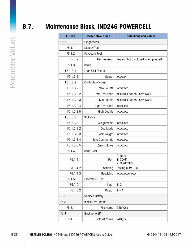
B-26 METTLER TOLEDO IND246 and IND246 POWERCELL User's Guide 64084448 | 03 | 12/2017
Para
met
er V
alue
s
B.7. Maintenance Block, IND246 POWERCELL F-Code Descriptive Name Selections and Values
F5.1 Diagnostics
F5.1.1 Display Test
F5.1.2 Keyboard Test
F5.1.2.1 Key Pressed: Key symbol displayed when pressed
F5.1.3 Scale
F5.1.3.1 Load Cell Output
F5.1.3.1.1 Output xxxxxxx
F5.1.3.2 Calibration Values
F5.1.3.2.1 Zero Counts xxxxxxxx
F5.1.3.2.2 Mid Test Load Xxxxxxxx not on POWERCELL
F5.1.3.2.3 Mid Counts Xxxxxxxx not on POWERCELL
F5.1.3.2.4 High Test Load xxxxxxxx
F5.1.3.2.5 High Counts xxxxxxxx
F5.1.3.3 Statistics
F5.1.3.3.1 Weighments xxxxxxxx
F5.1.3.3.2 Overloads xxxxxxxx
F5.1.3.3.3 Peak Weight xxxxxxxx
F5.1.3.3.4 Zero Commands xxxxxxxx
F5.1.3.3.5 Zero Failures xxxxxxxx
F5.1.4 Serial Test
F5.1.4.1 Port 0: None 1: COM1 2: COM2/lUSB
F5.1.4.2 Sending Testing COM1: xx
F5.1.4.3 Receiving xxxxxxxxxxxxxx
F5.1.5 Discrete I/O Test
F5.1.5.1 Input 1, 2
F5.1.5.2 Output 1 – 4
F5.2 Replace Battery
F5.3 Install SW Update
F5.3.1 File Name 246A0xx
F5.4 Backup to SD
F5.4.1 Dataset Name 246_xx
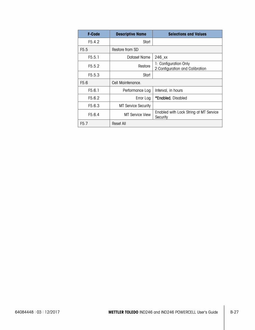
64084448 | 03 | 12/2017 METTLER TOLEDO IND246 and IND246 POWERCELL User's Guide B-27
F-Code Descriptive Name Selections and Values
F5.4.2 Start
F5.5 Restore from SD
F5.5.1 Dataset Name 246_xx
F5.5.2 Restore 1: Configuration Only 2:Configuration and Calibration
F5.5.3 Start
F5.6 Cell Maintenance.
F5.6.1 Performance Log Interval, in hours
F5.6.2 Error Log *Enabled, Disabled
F5.6.3 MT Service Security
F5.6.4 MT Service View Enabled with Lock String at MT Service Security
F5.7 Reset All
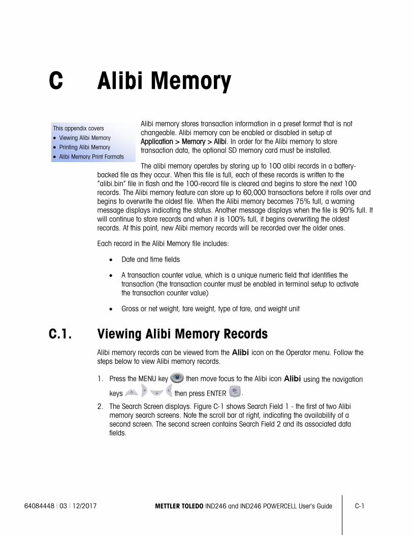
64084448 | 03 | 12/2017 METTLER TOLEDO IND246 and IND246 POWERCELL User's Guide
C-1
This appendix covers
• Viewing Alibi Memory
• Printing Alibi Memory
• Alibi Memory Print Formats
C Alibi Memory Alibi memory stores transaction information in a preset format that is not changeable. Alibi memory can be enabled or disabled in setup at Application > Memory > Alibi. In order for the Alibi memory to store transaction data, the optional SD memory card must be installed.
The alibi memory operates by storing up to 100 alibi records in a battery-backed file as they occur. When this file is full, each of these records is written to the “alibi.bin” file in flash and the 100-record file is cleared and begins to store the next 100 records. The Alibi memory feature can store up to 60,000 transactions before it rolls over and begins to overwrite the oldest file. When the Alibi memory becomes 75% full, a warning message displays indicating the status. Another message displays when the file is 90% full. It will continue to store records and when it is 100% full, it begins overwriting the oldest records. At this point, new Alibi memory records will be recorded over the older ones.
Each record in the Alibi Memory file includes:
• Date and time fields
• A transaction counter value, which is a unique numeric field that identifies the transaction (the transaction counter must be enabled in terminal setup to activate the transaction counter value)
• Gross or net weight, tare weight, type of tare, and weight unit
C.1. Viewing Alibi Memory Records Alibi memory records can be viewed from the icon on the Operator menu. Follow the steps below to view Alibi memory records.
1. Press the MENU key then move focus to the Alibi icon using the navigation
keys then press ENTER .
2. The Search Screen displays. Figure C-1 shows Search Field 1 - the first of two Alibi memory search screens. Note the scroll bar at right, indicating the availability of a second screen. The second screen contains Search Field 2 and its associated data fields.
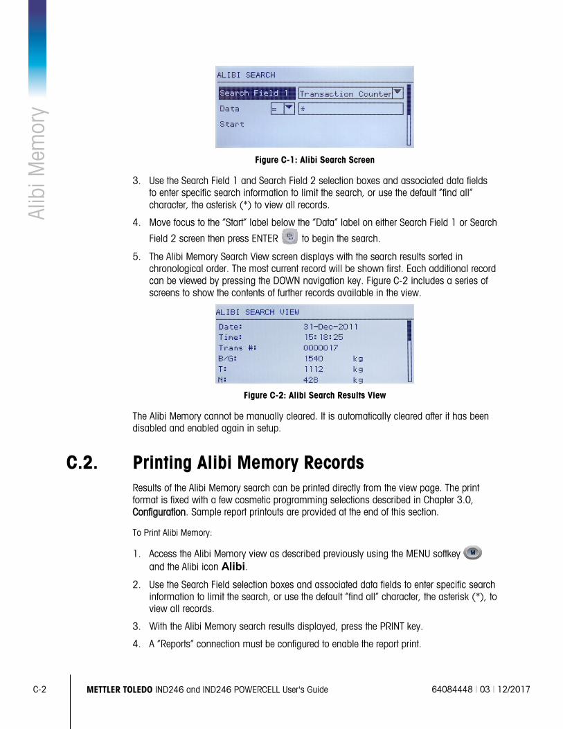
C-2
METTLER TOLEDO IND246 and IND246 POWERCELL User's Guide 64084448 | 03 | 12/2017
Alib
i Mem
ory
Figure C-1: Alibi Search Screen
3. Use the Search Field 1 and Search Field 2 selection boxes and associated data fields to enter specific search information to limit the search, or use the default “find all” character, the asterisk (*) to view all records.
4. Move focus to the “Start” label below the “Data” label on either Search Field 1 or Search
Field 2 screen then press ENTER to begin the search.
5. The Alibi Memory Search View screen displays with the search results sorted in chronological order. The most current record will be shown first. Each additional record can be viewed by pressing the DOWN navigation key. Figure C-2 includes a series of screens to show the contents of further records available in the view.
Figure C-2: Alibi Search Results View
The Alibi Memory cannot be manually cleared. It is automatically cleared after it has been disabled and enabled again in setup.
C.2. Printing Alibi Memory Records Results of the Alibi Memory search can be printed directly from the view page. The print format is fixed with a few cosmetic programming selections described in Chapter 3.0, Configuration. Sample report printouts are provided at the end of this section.
To Print Alibi Memory:
1. Access the Alibi Memory view as described previously using the MENU softkey and the Alibi icon Alibi.
2. Use the Search Field selection boxes and associated data fields to enter specific search information to limit the search, or use the default “find all” character, the asterisk (*), to view all records.
3. With the Alibi Memory search results displayed, press the PRINT key.
4. A “Reports” connection must be configured to enable the report print.
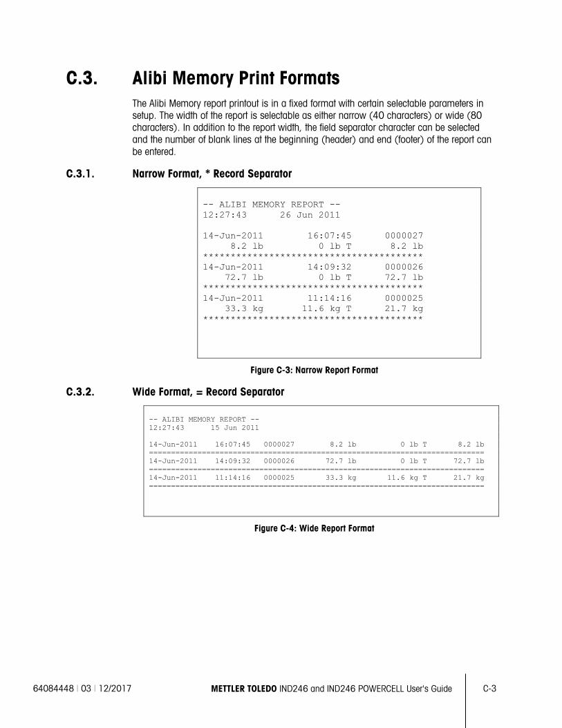
64084448 | 03 | 12/2017 METTLER TOLEDO IND246 and IND246 POWERCELL User's Guide
C-3
C.3. Alibi Memory Print Formats The Alibi Memory report printout is in a fixed format with certain selectable parameters in setup. The width of the report is selectable as either narrow (40 characters) or wide (80 characters). In addition to the report width, the field separator character can be selected and the number of blank lines at the beginning (header) and end (footer) of the report can be entered.
C.3.1. Narrow Format, * Record Separator
-- ALIBI MEMORY REPORT -- 12:27:43 26 Jun 2011 14-Jun-2011 16:07:45 0000027 8.2 lb 0 lb T 8.2 lb **************************************** 14-Jun-2011 14:09:32 0000026 72.7 lb 0 lb T 72.7 lb **************************************** 14-Jun-2011 11:14:16 0000025 33.3 kg 11.6 kg T 21.7 kg ****************************************
Figure C-3: Narrow Report Format
C.3.2. Wide Format, = Record Separator
-- ALIBI MEMORY REPORT -- 12:27:43 15 Jun 2011 14-Jun-2011 16:07:45 0000027 8.2 lb 0 lb T 8.2 lb ============================================================================ 14-Jun-2011 14:09:32 0000026 72.7 lb 0 lb T 72.7 lb ============================================================================ 14-Jun-2011 11:14:16 0000025 33.3 kg 11.6 kg T 21.7 kg ============================================================================
Figure C-4: Wide Report Format
64084448 | 03 | 12/2017 METTLER TOLEDO IND246 and IND246 POWERCELL User's Guide D-1
This appendix covers
• Serial Interface Parameters
• Demand Output Mode
• Continuous Output Modes
• CTPZ
• SICS Protocol
• Reports
• Variable Access
D Communications
D.1. Serial Interface Parameters One standard serial port and one optional serial port are supported with the IND246 terminal. They are designated COM1 (standard port on the Main PCB) and COM2 (optional).
For the standard IND246 terminal COM1 provides an RS-232 interface only. For the IND246 POWERCELL terminal there is a choice of a RS-232, RS-422 or RS-485 interface. The RS-232 interface is a three-wire (TDX, RXD, and GND) with selectable XON-XOFF handshaking.The RS-232 interface is a three-wire (TDX, RXD, and GND) with selectable XON-XOFF handshaking. The RS-485 connection is a two-wire interface but does not support multi-drop communication with addressing. The port must be selected for use as either RS-232 or RS-485 due to the different operating requirements of the
interfaces.
Optional COM2 provides RS-232 and RS-485 interfaces.
Character framing is programmable in the setup mode. Framing can be:
• 1 start bit
• 7 or 8 ASCII data bits (selectable)
• 0 or 1 parity bit (selectable as none, even, or odd)
• 1 stop bit
The baud rate can be configured from 300 to 115.2K baud and a checksum character can also be configured when using one of the continuous output strings.
The IND246 terminal supports the following functions on the serial ports:
• Demand output with CTPZ input
• Continuous output with CTPZ input
• Extended continuous output with CTPZ input
• SICS (level 0 and level 1)
• Reports
• Variable access (COM1 only)
• Continuous – Multi 1 (selectable when animal weighing is active)
• Continuous – Multi 2 (selectable when animal weighing is active)
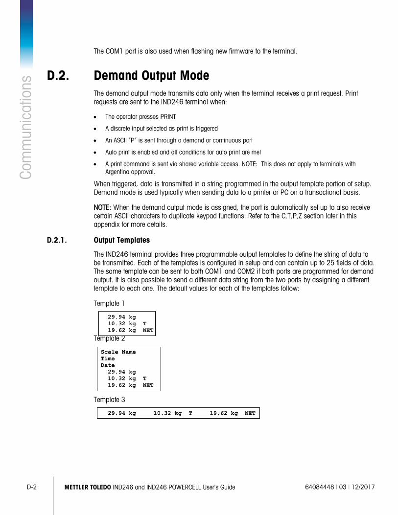
D-2 METTLER TOLEDO IND246 and IND246 POWERCELL User's Guide 64084448 | 03 | 12/2017
Com
mun
icat
ions
The COM1 port is also used when flashing new firmware to the terminal.
D.2. Demand Output Mode The demand output mode transmits data only when the terminal receives a print request. Print requests are sent to the IND246 terminal when:
• The operator presses PRINT
• A discrete input selected as print is triggered
• An ASCII “P” is sent through a demand or continuous port
• Auto print is enabled and all conditions for auto print are met
• A print command is sent via shared variable access. NOTE: This does not apply to terminals with Argentina approval.
When triggered, data is transmitted in a string programmed in the output template portion of setup. Demand mode is used typically when sending data to a printer or PC on a transactional basis.
NOTE: When the demand output mode is assigned, the port is automatically set up to also receive certain ASCII characters to duplicate keypad functions. Refer to the C,T,P,Z section later in this appendix for more details.
D.2.1. Output Templates
The IND246 terminal provides three programmable output templates to define the string of data to be transmitted. Each of the templates is configured in setup and can contain up to 25 fields of data. The same template can be sent to both COM1 and COM2 if both ports are programmed for demand output. It is also possible to send a different data string from the two ports by assigning a different template to each one. The detault values for each of the templates follow:
Template 1
29.94 kg 10.32 kg T 19.62 kg NET
Template 2
Scale Name Time Date 29.94 kg 10.32 kg T 19.62 kg NET
Template 3
29.94 kg 10.32 kg T 19.62 kg NET
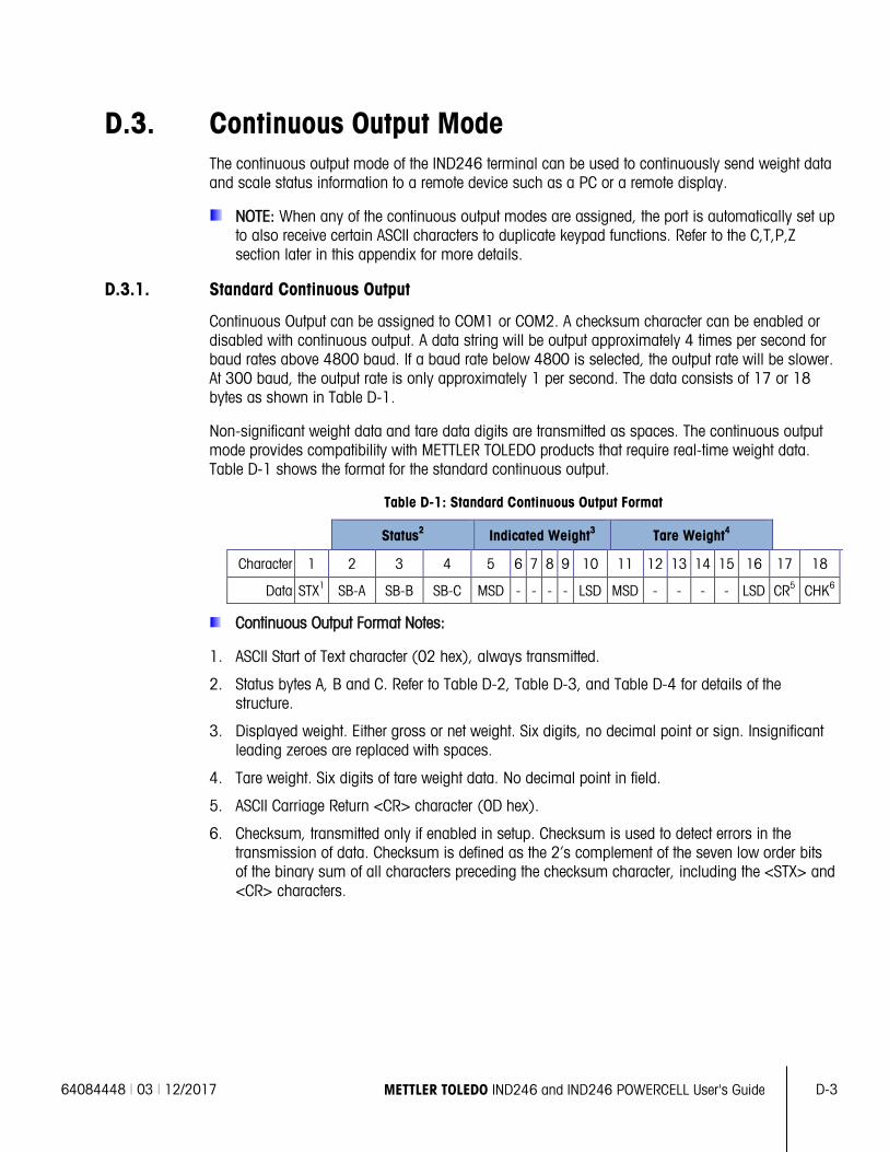
64084448 | 03 | 12/2017 METTLER TOLEDO IND246 and IND246 POWERCELL User's Guide D-3
D.3. Continuous Output Mode The continuous output mode of the IND246 terminal can be used to continuously send weight data and scale status information to a remote device such as a PC or a remote display.
NOTE: When any of the continuous output modes are assigned, the port is automatically set up to also receive certain ASCII characters to duplicate keypad functions. Refer to the C,T,P,Z section later in this appendix for more details.
D.3.1. Standard Continuous Output
Continuous Output can be assigned to COM1 or COM2. A checksum character can be enabled or disabled with continuous output. A data string will be output approximately 4 times per second for baud rates above 4800 baud. If a baud rate below 4800 is selected, the output rate will be slower. At 300 baud, the output rate is only approximately 1 per second. The data consists of 17 or 18 bytes as shown in Table D-1.
Non-significant weight data and tare data digits are transmitted as spaces. The continuous output mode provides compatibility with METTLER TOLEDO products that require real-time weight data. Table D-1 shows the format for the standard continuous output.
Table D-1: Standard Continuous Output Format
Status2 Indicated Weight3 Tare Weight4
Character 1 2 3 4 5 6 7 8 9 10 11 12 13 14 15 16 17 18
Data STX1 SB-A SB-B SB-C MSD - - - - LSD MSD - - - - LSD CR5 CHK6
Continuous Output Format Notes:
1. ASCII Start of Text character (02 hex), always transmitted.
2. Status bytes A, B and C. Refer to Table D-2, Table D-3, and Table D-4 for details of the structure.
3. Displayed weight. Either gross or net weight. Six digits, no decimal point or sign. Insignificant leading zeroes are replaced with spaces.
4. Tare weight. Six digits of tare weight data. No decimal point in field.
5. ASCII Carriage Return <CR> character (0D hex).
6. Checksum, transmitted only if enabled in setup. Checksum is used to detect errors in the transmission of data. Checksum is defined as the 2’s complement of the seven low order bits of the binary sum of all characters preceding the checksum character, including the <STX> and <CR> characters.
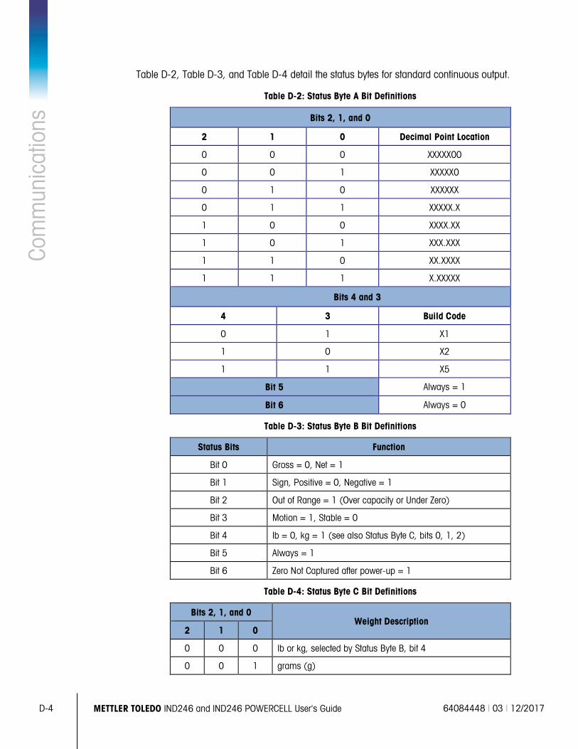
D-4 METTLER TOLEDO IND246 and IND246 POWERCELL User's Guide 64084448 | 03 | 12/2017
Com
mun
icat
ions
Table D-2, Table D-3, and Table D-4 detail the status bytes for standard continuous output.
Table D-2: Status Byte A Bit Definitions
Bits 2, 1, and 0
2 1 0 Decimal Point Location
0 0 0 XXXXX00
0 0 1 XXXXX0
0 1 0 XXXXXX
0 1 1 XXXXX.X
1 0 0 XXXX.XX
1 0 1 XXX.XXX
1 1 0 XX.XXXX
1 1 1 X.XXXXX
Bits 4 and 3
4 3 Build Code
0 1 X1
1 0 X2
1 1 X5
Bit 5 Always = 1
Bit 6 Always = 0
Table D-3: Status Byte B Bit Definitions
Status Bits Function
Bit 0 Gross = 0, Net = 1
Bit 1 Sign, Positive = 0, Negative = 1
Bit 2 Out of Range = 1 (Over capacity or Under Zero)
Bit 3 Motion = 1, Stable = 0
Bit 4 lb = 0, kg = 1 (see also Status Byte C, bits 0, 1, 2)
Bit 5 Always = 1
Bit 6 Zero Not Captured after power-up = 1
Table D-4: Status Byte C Bit Definitions
Bits 2, 1, and 0 Weight Description
2 1 0
0 0 0 lb or kg, selected by Status Byte B, bit 4
0 0 1 grams (g)
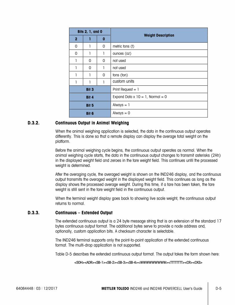
64084448 | 03 | 12/2017 METTLER TOLEDO IND246 and IND246 POWERCELL User's Guide D-5
Bits 2, 1, and 0 Weight Description
2 1 0
0 1 0 metric tons (t)
0 1 1 ounces (oz)
1 0 0 not used
1 0 1 not used
1 1 0 tons (ton)
1 1 1 custom units
Bit 3 Print Request = 1
Bit 4 Expand Data x 10 = 1, Normal = 0
Bit 5 Always = 1
Bit 6 Always = 0
D.3.2. Continuous Output in Animal Weighing
When the animal weighing application is selected, the data in the continuous output operates differently. This is done so that a remote display can display the average total weight on the platform.
Before the animal weighing cycle begins, the continuous output operates as normal. When the animal weighing cycle starts, the data in the continuous output changes to transmit asterisks (2Ah) in the displayed weight field and zeroes in the tare weight field. This continues until the processed weight is determined.
After the averaging cycle, the averaged weight is shown on the IND246 display, and the continuous output transmits the averaged weight in the displayed weight field. This continues as long as the display shows the processed average weight. During this time, if a tare has been taken, the tare weight is still sent in the tare weight field in the continuous output.
When the terminal weight display goes back to showing live scale weight, the continuous output returns to normal.
D.3.3. Continuous – Extended Output
The extended continuous output is a 24 byte message string that is an extension of the standard 17 bytes continuous output format. The additional bytes serve to provide a node address and, optionally, custom application bits. A checksum character is selectable.
The IND246 terminal supports only the point-to-point application of the extended continuous format. The multi-drop application is not supported.
Table D-5 describes the extended continuous output format. The output takes the form shown here:
<SOH><ADR><SB-1><SB-2><SB-3><SB-4><WWWWWWWWW><TTTTTTTT><CR><CKS>
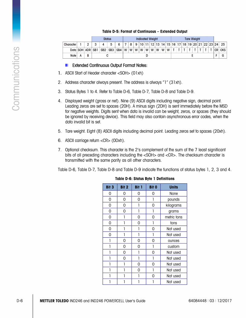
D-6 METTLER TOLEDO IND246 and IND246 POWERCELL User's Guide 64084448 | 03 | 12/2017
Com
mun
icat
ions
Table D-5: Format of Continuous – Extended Output
Extended Continuous Output Format Notes:
1. ASCII Start of Header character <SOH> (01xh)
2. Address character always present. The address is always “1” (31xh).
3. Status Bytes 1 to 4. Refer to Table D-6, Table D-7, Table D-8 and Table D-9.
4. Displayed weight (gross or net). Nine (9) ASCII digits including negative sign, decimal point. Leading zeros are set to spaces (20H). A minus sign (2DH) is sent immediately before the MSD for negative weights. Digits sent when data is invalid can be weight, zeros, or spaces (they should be ignored by receiving device). This field may also contain asynchronous error codes, when the data invalid bit is set.
5. Tare weight. Eight (8) ASCII digits including decimal point. Leading zeros set to spaces (20xh).
6. ASCII carriage return <CR> (0Dxh).
7. Optional checksum. This character is the 2's complement of the sum of the 7 least significant bits of all preceding characters including the <SOH> and <CR>. The checksum character is transmitted with the same parity as all other characters.
Table D-6, Table D-7, Table D-8 and Table D-9 indicate the functions of status bytes 1, 2, 3 and 4.
Table D-6: Status Byte 1 Definitions
Bit 3 Bit 2 Bit 1 Bit 0 Units
0 0 0 0 None 0 0 0 1 pounds 0 0 1 0 kilograms 0 0 1 1 grams 0 1 0 0 metric tons 0 1 0 1 tons 0 1 1 0 Not used 0 1 1 1 Not used 1 0 0 0 ounces 1 0 0 1 custom 1 0 1 0 Not used 1 0 1 1 Not used 1 1 0 0 Not used 1 1 0 1 Not used 1 1 1 0 Not used 1 1 1 1 Not used

64084448 | 03 | 12/2017 METTLER TOLEDO IND246 and IND246 POWERCELL User's Guide D-7
Bit 3 Bit 2 Bit 1 Bit 0 Units
Bit 4 Center of zero = 1
Bit 5 Always = 1
Bit 6 Weight in motion = 1
Table D-7: Status Byte 2 Definitions
Bit Description
Bit 0 Gross or net mode, Net = 1
Bit 2 Bit 1 Tare type
0 0 No tare
0 1 Semi-automatic tare
1 0 Preset tare
1 1 Not used
Bit 3 Always = 0
Bit 4 Always = 0
Bit 5 Always = 1
Bit 6 Expanded by x10 = 1
Table D-8: Status Byte 3 Definitions
Bit Description
0 Data invalid = 1
1 Out of range under zero = 1
2 Out of range over capacity = 1
3 In power up (zero not captured) = 1
4 Print initiated = 1
5 Always = 1
6 Not used
Table D-9: Status Byte 4 Definitions
Bit Description
0 Always = 0
1 Always = 0
2 Always = 0
3 Always = 0
4 Always = 0
5 Always = 1
6 Always = 0
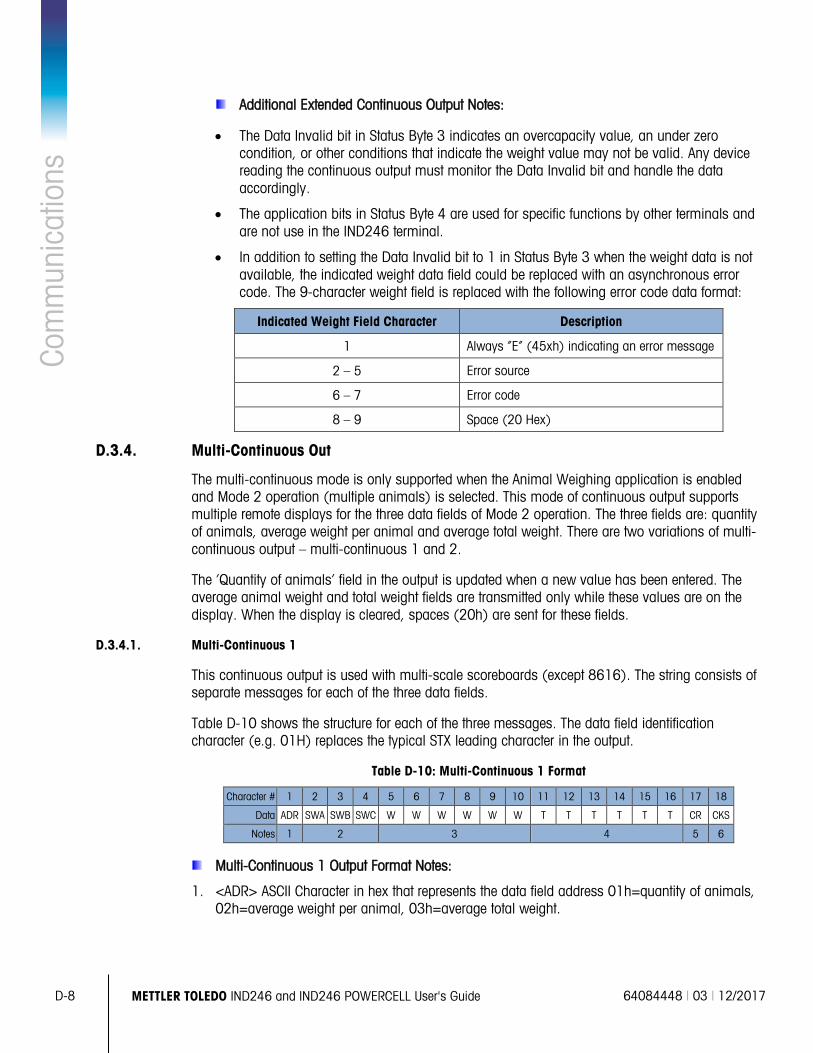
D-8 METTLER TOLEDO IND246 and IND246 POWERCELL User's Guide 64084448 | 03 | 12/2017
Com
mun
icat
ions
Additional Extended Continuous Output Notes:
• The Data Invalid bit in Status Byte 3 indicates an overcapacity value, an under zero condition, or other conditions that indicate the weight value may not be valid. Any device reading the continuous output must monitor the Data Invalid bit and handle the data accordingly.
• The application bits in Status Byte 4 are used for specific functions by other terminals and are not use in the IND246 terminal.
• In addition to setting the Data Invalid bit to 1 in Status Byte 3 when the weight data is not available, the indicated weight data field could be replaced with an asynchronous error code. The 9-character weight field is replaced with the following error code data format:
Indicated Weight Field Character Description
1 Always “E” (45xh) indicating an error message
2 – 5 Error source
6 – 7 Error code
8 – 9 Space (20 Hex)
D.3.4. Multi-Continuous Out
The multi-continuous mode is only supported when the Animal Weighing application is enabled and Mode 2 operation (multiple animals) is selected. This mode of continuous output supports multiple remote displays for the three data fields of Mode 2 operation. The three fields are: quantity of animals, average weight per animal and average total weight. There are two variations of multi-continuous output – multi-continuous 1 and 2.
The ‘Quantity of animals’ field in the output is updated when a new value has been entered. The average animal weight and total weight fields are transmitted only while these values are on the display. When the display is cleared, spaces (20h) are sent for these fields.
D.3.4.1. Multi-Continuous 1
This continuous output is used with multi-scale scoreboards (except 8616). The string consists of separate messages for each of the three data fields.
Table D-10 shows the structure for each of the three messages. The data field identification character (e.g. 01H) replaces the typical STX leading character in the output.
Table D-10: Multi-Continuous 1 Format
Character # 1 2 3 4 5 6 7 8 9 10 11 12 13 14 15 16 17 18
Data ADR SWA SWB SWC W W W W W W T T T T T T CR CKS
Notes 1 2 3 4 5 6
Multi-Continuous 1 Output Format Notes:
1. <ADR> ASCII Character in hex that represents the data field address 01h=quantity of animals, 02h=average weight per animal, 03h=average total weight.
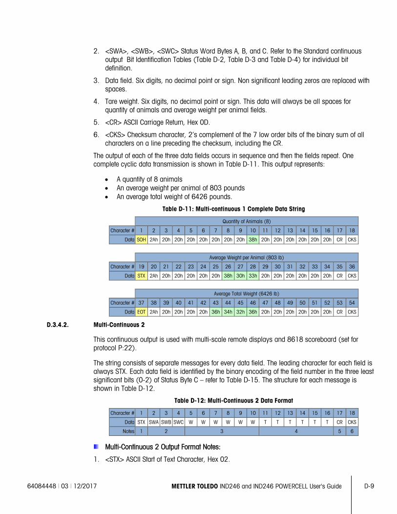
64084448 | 03 | 12/2017 METTLER TOLEDO IND246 and IND246 POWERCELL User's Guide D-9
2. <SWA>, <SWB>, <SWC> Status Word Bytes A, B, and C. Refer to the Standard continuous output Bit Identification Tables (Table D-2, Table D-3 and Table D-4) for individual bit definition.
3. Data field. Six digits, no decimal point or sign. Non significant leading zeros are replaced with spaces.
4. Tare weight. Six digits, no decimal point or sign. This data will always be all spaces for quantity of animals and average weight per animal fields.
5. <CR> ASCII Carriage Return, Hex 0D.
6. <CKS> Checksum character, 2’s complement of the 7 low order bits of the binary sum of all characters on a line preceding the checksum, including the CR.
The output of each of the three data fields occurs in sequence and then the fields repeat. One complete cyclic data transmission is shown in Table D-11. This output represents:
• A quantity of 8 animals • An average weight per animal of 803 pounds • An average total weight of 6426 pounds.
Table D-11: Multi-continuous 1 Complete Data String
Quantity of Animals (8)
Character # 1 2 3 4 5 6 7 8 9 10 11 12 13 14 15 16 17 18
Data SOH 2Ah 20h 20h 20h 20h 20h 20h 20h 38h 20h 20h 20h 20h 20h 20h CR CKS
Average Weight per Animal (803 lb)
Character # 19 20 21 22 23 24 25 26 27 28 29 30 31 32 33 34 35 36
Data STX 2Ah 20h 20h 20h 20h 20h 38h 30h 33h 20h 20h 20h 20h 20h 20h CR CKS
Average Total Weight (6426 lb)
Character # 37 38 39 40 41 42 43 44 45 46 47 48 49 50 51 52 53 54
Data EOT 2Ah 20h 20h 20h 20h 36h 34h 32h 36h 20h 20h 20h 20h 20h 20h CR CKS
D.3.4.2. Multi-Continuous 2
This continuous output is used with multi-scale remote displays and 8618 scoreboard (set for protocol P:22).
The string consists of separate messages for every data field. The leading character for each field is always STX. Each data field is identified by the binary encoding of the field number in the three least significant bits (0-2) of Status Byte C – refer to Table D-15. The structure for each message is shown in Table D-12.
Table D-12: Multi-Continuous 2 Data Format
Character # 1 2 3 4 5 6 7 8 9 10 11 12 13 14 15 16 17 18
Data STX SWA SWB SWC W W W W W W T T T T T T CR CKS
Notes 1 2 3 4 5 6
Multi-Continuous 2 Output Format Notes:
1. <STX> ASCII Start of Text Character, Hex 02.
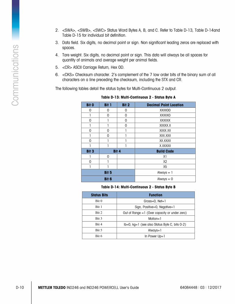
D-10 METTLER TOLEDO IND246 and IND246 POWERCELL User's Guide 64084448 | 03 | 12/2017
Com
mun
icat
ions
2. <SWA>, <SWB>, <SWC> Status Word Bytes A, B, and C. Refer to Table D-13, Table D-14and
Table D-15 for individual bit definition.
3. Data field. Six digits, no decimal point or sign. Non significant leading zeros are replaced with spaces.
4. Tare weight. Six digits, no decimal point or sign. This data will always be all spaces for quantity of animals and average weight per animal fields.
5. <CR> ASCII Carriage Return, Hex 0D.
6. <CKS> Checksum character. 2’s complement of the 7 low order bits of the binary sum of all characters on a line preceding the checksum, including the STX and CR.
The following tables detail the status bytes for Multi-Continuous 2 output.
Table D-13: Multi-Continuous 2 - Status Byte A
Bit 0 Bit 1 Bit 2 Decimal Point Location 0 0 0 XXXX00 1 0 0 XXXXX0 0 1 0 XXXXXX 1 1 0 XXXXX.X 0 0 1 XXXX.XX 1 0 1 XXX.XXX 0 1 1 XX.XXXX 1 1 1 X.XXXXX
Bit 3 Bit 4 Build Code 1 0 X1 0 1 X2 1 1 X5
Bit 5 Always = 1
Bit 6 Always = 0
Table D-14: Multi-Continuous 2 - Status Byte B
Status Bits Function Bit 0 Gross=0, Net=1
Bit 1 Sign, Positive=0, Negative=1
Bit 2 Out of Range =1 (Over capacity or under zero)
Bit 3 Motion=1
Bit 4 lb=0, kg=1 (see also Status Byte C, bits 0-2)
Bit 5 Always=1
Bit 6 In Power Up=1
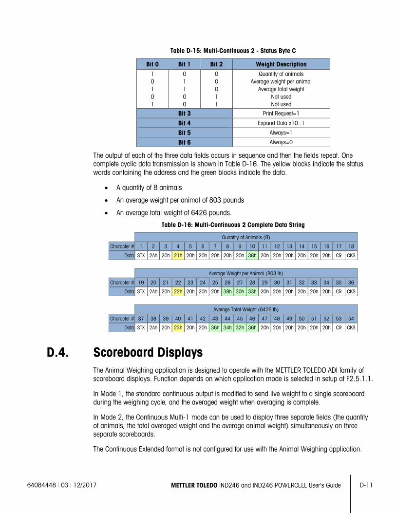
64084448 | 03 | 12/2017 METTLER TOLEDO IND246 and IND246 POWERCELL User's Guide D-11
Table D-15: Multi-Continuous 2 - Status Byte C
Bit 0 Bit 1 Bit 2 Weight Description 1 0 1 0 1
0 1 1 0 0
0 0 0 1 1
Quantity of animals Average weight per animal
Average total weight Not used Not used
Bit 3 Print Request=1
Bit 4 Expand Data x10=1
Bit 5 Always=1
Bit 6 Always=0
The output of each of the three data fields occurs in sequence and then the fields repeat. One complete cyclic data transmission is shown in Table D-16. The yellow blocks indicate the status words containing the address and the green blocks indicate the data.
• A quantity of 8 animals
• An average weight per animal of 803 pounds
• An average total weight of 6426 pounds.
Table D-16: Multi-Continuous 2 Complete Data String
Quantity of Animals (8)
Character # 1 2 3 4 5 6 7 8 9 10 11 12 13 14 15 16 17 18
Data STX 2Ah 20h 21h 20h 20h 20h 20h 20h 38h 20h 20h 20h 20h 20h 20h CR CKS
Average Weight per Animal (803 lb)
Character # 19 20 21 22 23 24 25 26 27 28 29 30 31 32 33 34 35 36
Data STX 2Ah 20h 22h 20h 20h 20h 38h 30h 33h 20h 20h 20h 20h 20h 20h CR CKS
Average Total Weight (6426 lb)
Character # 37 38 39 40 41 42 43 44 45 46 47 48 49 50 51 52 53 54
Data STX 2Ah 20h 23h 20h 20h 36h 34h 32h 36h 20h 20h 20h 20h 20h 20h CR CKS
D.4. Scoreboard Displays The Animal Weighing application is designed to operate with the METTLER TOLEDO ADI family of scoreboard displays. Function depends on which application mode is selected in setup at F2.5.1.1.
In Mode 1, the standard continuous output is modified to send live weight to a single scoreboard during the weighing cycle, and the averaged weight when averaging is complete.
In Mode 2, the Continuous Multi-1 mode can be used to display three separate fields (the quantity of animals, the total averaged weight and the average animal weight) simultaneously on three separate scoreboards.
The Continuous Extended format is not configured for use with the Animal Weighing application.
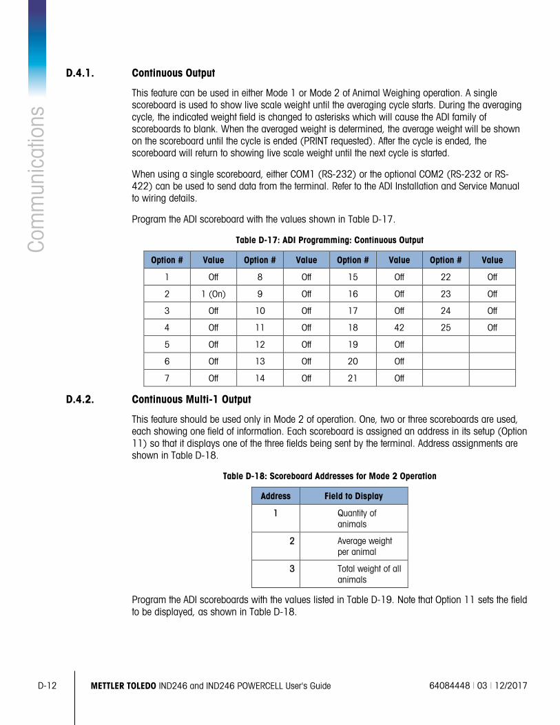
D-12 METTLER TOLEDO IND246 and IND246 POWERCELL User's Guide 64084448 | 03 | 12/2017
Com
mun
icat
ions
D.4.1. Continuous Output
This feature can be used in either Mode 1 or Mode 2 of Animal Weighing operation. A single scoreboard is used to show live scale weight until the averaging cycle starts. During the averaging cycle, the indicated weight field is changed to asterisks which will cause the ADI family of scoreboards to blank. When the averaged weight is determined, the average weight will be shown on the scoreboard until the cycle is ended (PRINT requested). After the cycle is ended, the scoreboard will return to showing live scale weight until the next cycle is started.
When using a single scoreboard, either COM1 (RS-232) or the optional COM2 (RS-232 or RS-422) can be used to send data from the terminal. Refer to the ADI Installation and Service Manual to wiring details.
Program the ADI scoreboard with the values shown in Table D-17.
Table D-17: ADI Programming: Continuous Output
Option # Value Option # Value Option # Value Option # Value
1 Off 8 Off 15 Off 22 Off
2 1 (On) 9 Off 16 Off 23 Off
3 Off 10 Off 17 Off 24 Off
4 Off 11 Off 18 42 25 Off
5 Off 12 Off 19 Off
6 Off 13 Off 20 Off
7 Off 14 Off 21 Off
D.4.2. Continuous Multi-1 Output
This feature should be used only in Mode 2 of operation. One, two or three scoreboards are used, each showing one field of information. Each scoreboard is assigned an address in its setup (Option 11) so that it displays one of the three fields being sent by the terminal. Address assignments are shown in Table D-18.
Table D-18: Scoreboard Addresses for Mode 2 Operation
Address Field to Display
1 Quantity of animals
2 Average weight per animal
3 Total weight of all animals
Program the ADI scoreboards with the values listed in Table D-19. Note that Option 11 sets the field to be displayed, as shown in Table D-18.
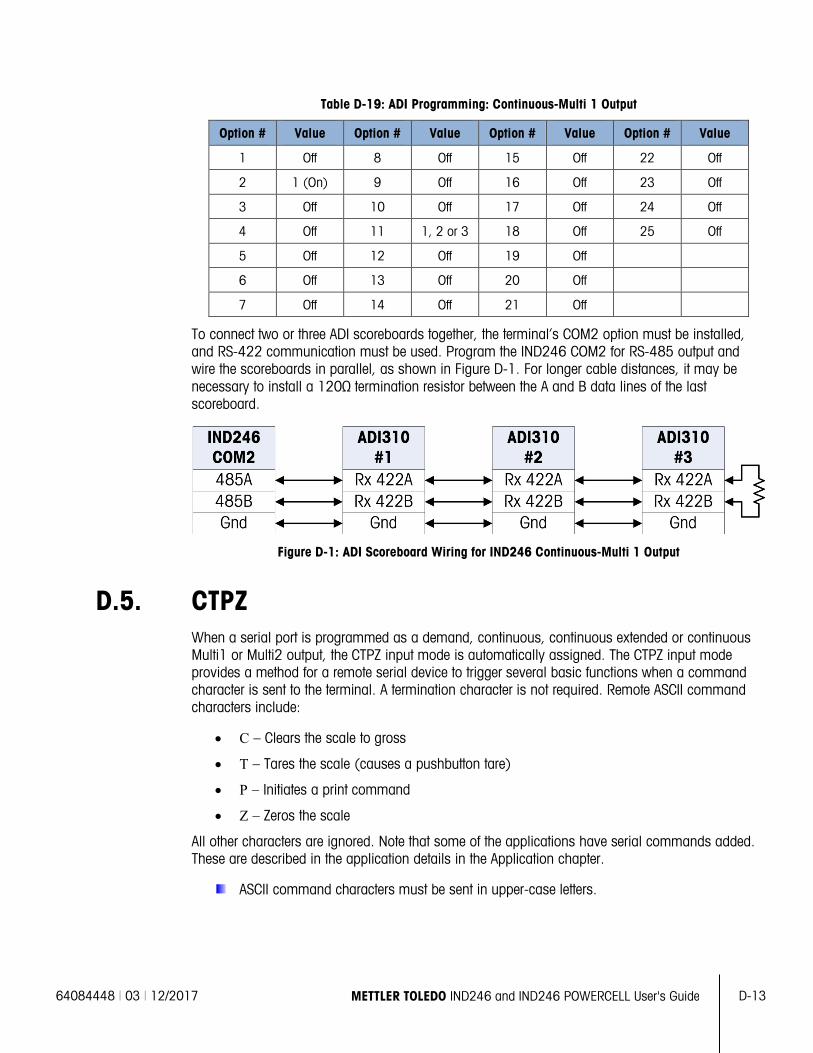
64084448 | 03 | 12/2017 METTLER TOLEDO IND246 and IND246 POWERCELL User's Guide D-13
Table D-19: ADI Programming: Continuous-Multi 1 Output
Option # Value Option # Value Option # Value Option # Value
1 Off 8 Off 15 Off 22 Off
2 1 (On) 9 Off 16 Off 23 Off
3 Off 10 Off 17 Off 24 Off
4 Off 11 1, 2 or 3 18 Off 25 Off
5 Off 12 Off 19 Off
6 Off 13 Off 20 Off
7 Off 14 Off 21 Off
To connect two or three ADI scoreboards together, the terminal’s COM2 option must be installed, and RS-422 communication must be used. Program the IND246 COM2 for RS-485 output and wire the scoreboards in parallel, as shown in Figure D-1. For longer cable distances, it may be necessary to install a 120Ω termination resistor between the A and B data lines of the last scoreboard.
Figure D-1: ADI Scoreboard Wiring for IND246 Continuous-Multi 1 Output
D.5. CTPZ When a serial port is programmed as a demand, continuous, continuous extended or continuous Multi1 or Multi2 output, the CTPZ input mode is automatically assigned. The CTPZ input mode provides a method for a remote serial device to trigger several basic functions when a command character is sent to the terminal. A termination character is not required. Remote ASCII command characters include:
• C – Clears the scale to gross
• T – Tares the scale (causes a pushbutton tare)
• P – Initiates a print command
• Z – Zeros the scale
All other characters are ignored. Note that some of the applications have serial commands added. These are described in the application details in the Application chapter.
ASCII command characters must be sent in upper-case letters.
D-14 METTLER TOLEDO IND246 and IND246 POWERCELL User's Guide 64084448 | 03 | 12/2017
Com
mun
icat
ions
Example
To initiate a pushbutton tare, program the terminal for demand or continuous output for a specific port, program the serial port parameters to match the other device and then send the ASCII character “T”.
D.6. Standard Interface Command Set (SICS) Protocol The IND246 terminal supports the METTLER TOLEDO Standard Interface Command Set (MT-SICS), which is divided into four levels (0, 1, 2, 3), depending on the functionality of the device. This terminal supports parts of levels 0 and 1:
• MT-SICS level 0 – Command set for the simplest device.
• MT-SICS level 1 – Extension of the command set for standard devices.
A feature of this interface is that the commands combined in MT-SICS level 0 and 1 are identical for all devices. Both the simplest weighing device and a fully expanded weighing workstation can recognize the commands of MT-SICS levels 0 and 1.
D.6.1. Version Number of the MT-SICS
Each level of the MT-SICS has its own version number, which can be requested with the command I1 from level 0. This terminal supports:
• MT-SICS level 0, version 2.2x (except the ZI command)
• MT-SICS level 1, version 2.2x (except the D, DW and K commands)
D.6.2. Command Formats
Each command received by the terminal via the SICS interface is acknowledged by a response to the transmitting device. Commands and responses are data strings with a fixed format. Commands sent to the terminal comprise one or more characters of the ASCII character set. Commands must be in upper-case.
The parameters of the command must be separated from one another and from the command name by a space (20xh), in the examples shown in this section, a space is represented as _ ).
Each command must be terminated by <CR>< LF> (0Dxh, 0Axh).
The characters <CR> and <LF>, which can be input using the ENTER or RETURN key of most PC terminal keypads, are not shown in this description; however, it is essential they be included for communication with the terminal.
Example
Command to tare the terminal:
“TA_20.00_lb” (The command terminators <CR>< LF> are not shown.)
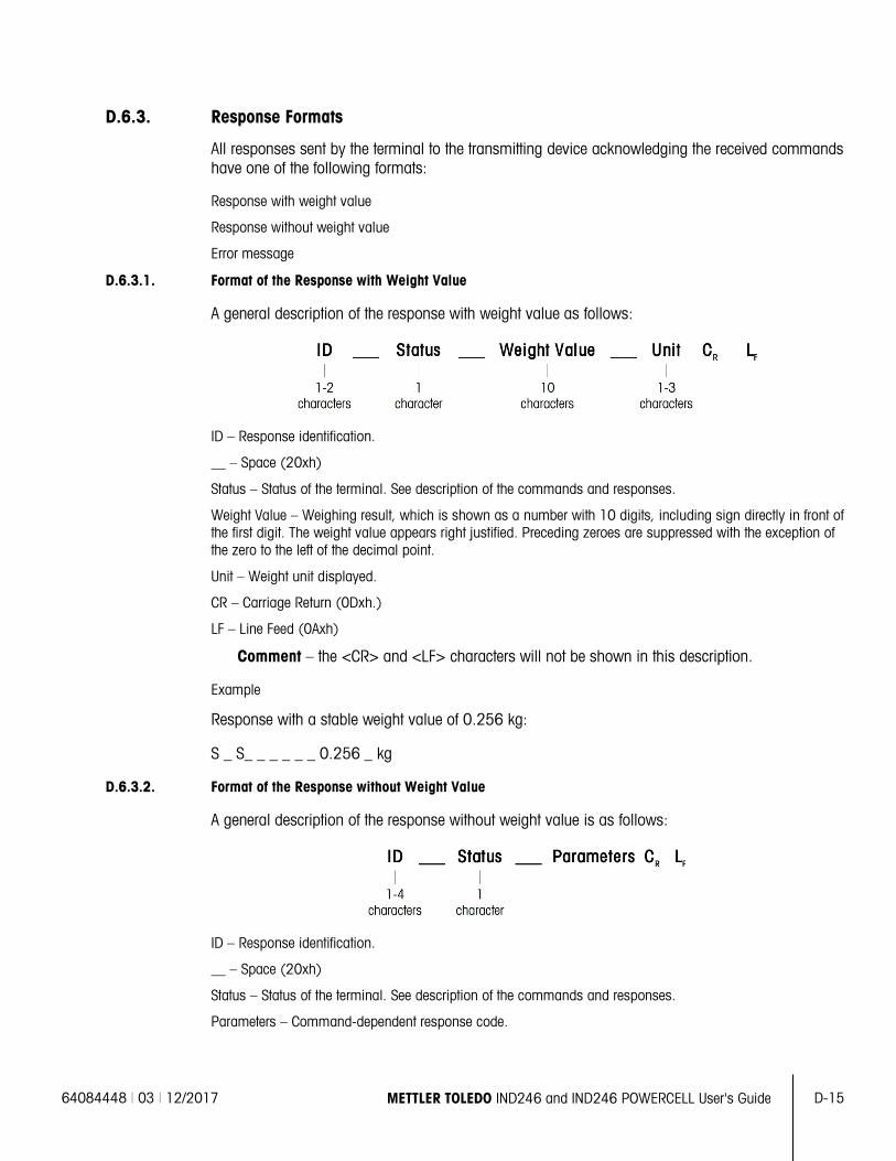
64084448 | 03 | 12/2017 METTLER TOLEDO IND246 and IND246 POWERCELL User's Guide D-15
D.6.3. Response Formats
All responses sent by the terminal to the transmitting device acknowledging the received commands have one of the following formats:
Response with weight value
Response without weight value
Error message
D.6.3.1. Format of the Response with Weight Value
A general description of the response with weight value as follows:
ID – Response identification.
__ – Space (20xh)
Status – Status of the terminal. See description of the commands and responses.
Weight Value – Weighing result, which is shown as a number with 10 digits, including sign directly in front of the first digit. The weight value appears right justified. Preceding zeroes are suppressed with the exception of the zero to the left of the decimal point.
Unit – Weight unit displayed.
CR – Carriage Return (0Dxh.)
LF – Line Feed (0Axh)
Comment – the <CR> and <LF> characters will not be shown in this description.
Example
Response with a stable weight value of 0.256 kg:
S _ S_ _ _ _ _ _ 0.256 _ kg
D.6.3.2. Format of the Response without Weight Value
A general description of the response without weight value is as follows:
ID – Response identification.
__ – Space (20xh)
Status – Status of the terminal. See description of the commands and responses.
Parameters – Command-dependent response code.
D-16 METTLER TOLEDO IND246 and IND246 POWERCELL User's Guide 64084448 | 03 | 12/2017
Com
mun
icat
ions
CR – Carriage Return (0Dxh)
LF – Line Feed (0Axh)
Comment – the <CR> and <LF> characters will not be shown in this description.
ID CR LF
D.6.3.3. Format of Error Message
There are three different error messages. The identification always comprises two characters:
ES – Syntax error The terminal has not recognized the received command.
ET – Transmission error The terminal has received a “faulty” command, such as a parity error.
EL – Logical error The terminal cannot execute the received command.
CR – Carriage return (0Dxh)
LF – Line Feed (0Axh)
Comment – the <CR> and <LF> characters will not be shown in this description.
D.6.4. Tips for the Programmer
Tips for creating a robust communication with the terminal using the SICS protocol include:
D.6.4.1. Command and Response
Improve the dependability of application software by having the program evaluate the response of the terminal to a command. The response is the acknowledgment that the terminal has received the command.
D.6.4.2. Reset
When establishing communication between the terminal and system, send a reset command to the terminal to enable a start from a determined state. When the terminal or system is switched on or off, faulty characters can be received or sent.
D.6.4.3. Quotation Marks (“ ”)
Quotation marks included in the command responses are used to designate fields and will always be sent.
D.6.5. Commands and Responses MT-SICS Level 0
The terminal receives a command from the system computer and acknowledges the command with an appropriate response. The following sections contain a detailed description of the command set in alphabetical order with the associated responses. Commands and responses are terminated with <CR> and <LF>. These termination characters are not shown in the following description, but they must always be entered with commands or sent with responses.
The following commands of MT-SICS level 0 are supported:
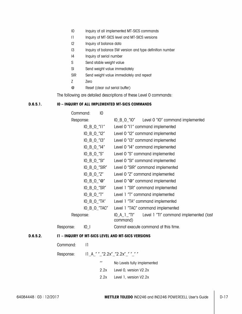
64084448 | 03 | 12/2017 METTLER TOLEDO IND246 and IND246 POWERCELL User's Guide D-17
I0 Inquiry of all implemented MT-SICS commands
I1 Inquiry of MT-SICS level and MT-SICS versions
I2 Inquiry of balance data
I3 Inquiry of balance SW version and type definition number
I4 Inquiry of serial number
S Send stable weight value
SI Send weight value immediately
SIR Send weight value immediately and repeat
Z Zero
@ Reset (clear out serial buffer)
The following are detailed descriptions of these Level 0 commands:
D.6.5.1. I0 – INQUIRY OF ALL IMPLEMENTED MT-SICS COMMANDS
Command: I0
Response: I0_B_0_“I0” Level 0 “IO” command implemented
I0_B_0_“I1” Level 0 “I1” command implemented
I0_B_0_“I2” Level 0 “I2” command implemented
I0_B_0_“I3” Level 0 “I3” command implemented
I0_B_0_“I4” Level 0 “I4” command implemented
I0_B_0_“S” Level 0 “S” command implemented
I0_B_0_“SI” Level 0 “SI” command implemented
I0_B_0_“SIR” Level 0 “SIR” command implemented
I0_B_0_“Z” Level 0 “Z” command implemented
I0_B_0_“@” Level 0 “@” command implemented
I0_B_0_“SR” Level 1 “SR” command implemented
I0_B_0_“T” Level 1 “T” command implemented
I0_B_0_“TA” Level 1 “TA” command implemented
I0_B_0_“TAC” Level 1 “TAC” command implemented
Response: I0_A_1_“TI” Level 1 “TI” command implemented (last command)
Response: I0_I Cannot execute command at this time.
D.6.5.2. I1 – INQUIRY OF MT-SICS LEVEL AND MT-SICS VERSIONS
Command: I1
Response: I1_A_“ ”_“2.2x”_“2.2x”_“ ”_“ ”
“” No Levels fully implemented
2.2x Level 0, version V2.2x
2.2x Level 1, version V2.2x
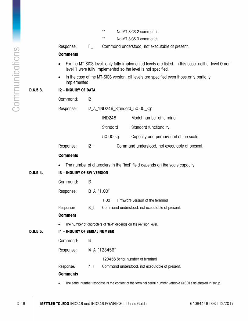
D-18 METTLER TOLEDO IND246 and IND246 POWERCELL User's Guide 64084448 | 03 | 12/2017
Com
mun
icat
ions
“” No MT-SICS 2 commands
“” No MT-SICS 3 commands
Response: I1_I Command understood, not executable at present.
Comments
• For the MT-SICS level, only fully implemented levels are listed. In this case, neither level 0 nor level 1 were fully implemented so the level is not specified.
• In the case of the MT-SICS version, all levels are specified even those only partially implemented.
D.6.5.3. I2 – INQUIRY OF DATA
Command: I2
Response: I2_A_“IND246_Standard_50.00_kg”
IND246 Model number of terminal
Standard Standard functionality
50.00 kg Capacity and primary unit of the scale
Response: I2_I Command understood, not executable at present.
Comments
• The number of characters in the “text” field depends on the scale capacity.
D.6.5.4. I3 – INQUIRY OF SW VERSION
Command: I3
Response: I3_A_“1.00”
1.00 Firmware version of the terminal
Response: I3_I Command understood, not executable at present.
Comment
• The number of characters of “text” depends on the revision level.
D.6.5.5. I4 – INQUIRY OF SERIAL NUMBER
Command: I4
Response: I4_A_“123456”
123456 Serial number of terminal
Response: I4_I Command understood, not executable at present.
Comments
• The serial number response is the content of the terminal serial number variable (#301) as entered in setup.
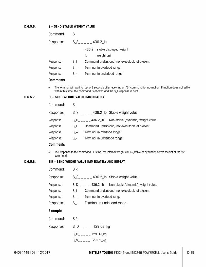
64084448 | 03 | 12/2017 METTLER TOLEDO IND246 and IND246 POWERCELL User's Guide D-19
D.6.5.6. S – SEND STABLE WEIGHT VALUE
Command: S
Response: S_S_ _ _ _ _ 436.2_lb
436.2 stable displayed weight
lb weight unit
Response: S_I Command understood, not executable at present.
Response: S_+ Terminal in overload range.
Response: S_- Terminal in underload range.
Comments
• The terminal will wait for up to 3 seconds after receiving an “S” command for no-motion. If motion does not settle within this time, the command is aborted and the S_I response is sent.
D.6.5.7. SI – SEND WEIGHT VALUE IMMEDIATELY
Command: SI
Response: S_S_ _ _ _ _ 436.2_lb Stable weight value.
Response: S_D_ _ _ _ _ 436.2_lb Non-stable (dynamic) weight value.
Response: S_I Command understood, not executable at present.
Response: S_+ Terminal in overload range.
Response: S_- Terminal in underload range.
Comments
• The response to the command SI is the last internal weight value (stable or dynamic) before receipt of the “SI” command.
D.6.5.8. SIR – SEND WEIGHT VALUE IMMEDIATELY AND REPEAT
Command: SIR
Response: S_S_ _ _ _ _ 436.2_lb Stable weight value.
Response: S_D_ _ _ _ _ 436.2_lb Non-stable (dynamic) weight value.
Response: S_I Command understood, not executable at present.
Response: S_+ Terminal in overload range.
Response: S_- Terminal in underload range
Example
Command: SIR
Response: S_D_ _ _ _ _ 129.07_kg
S_D_ _ _ _ _ 129.09_kg
S_S_ _ _ _ _ 129.09_kg
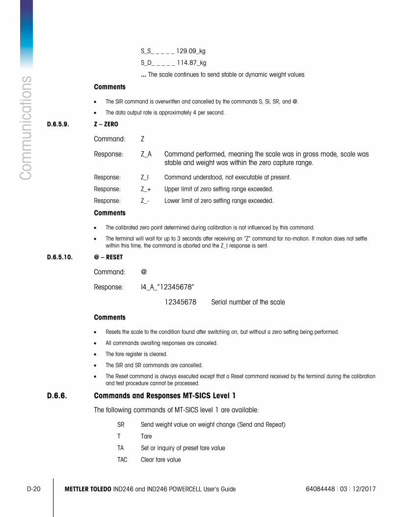
D-20 METTLER TOLEDO IND246 and IND246 POWERCELL User's Guide 64084448 | 03 | 12/2017
Com
mun
icat
ions
S_S_ _ _ _ _ 129.09_kg
S_D_ _ _ _ _ 114.87_kg
... The scale continues to send stable or dynamic weight values
Comments
• The SIR command is overwritten and cancelled by the commands S, SI, SR, and @.
• The data output rate is approximately 4 per second.
D.6.5.9. Z – ZERO
Command: Z
Response: Z_A Command performed, meaning the scale was in gross mode, scale was stable and weight was within the zero capture range.
Response: Z_I Command understood, not executable at present.
Response: Z_+ Upper limit of zero setting range exceeded.
Response: Z_- Lower limit of zero setting range exceeded.
Comments
• The calibrated zero point determined during calibration is not influenced by this command.
• The terminal will wait for up to 3 seconds after receiving an “Z” command for no-motion. If motion does not settle within this time, the command is aborted and the Z_I response is sent.
D.6.5.10. @ – RESET
Command: @
Response: I4_A_“12345678”
12345678 Serial number of the scale
Comments
• Resets the scale to the condition found after switching on, but without a zero setting being performed.
• All commands awaiting responses are canceled.
• The tare register is cleared.
• The SIR and SR commands are cancelled.
• The Reset command is always executed except that a Reset command received by the terminal during the calibration and test procedure cannot be processed.
D.6.6. Commands and Responses MT-SICS Level 1
The following commands of MT-SICS level 1 are available:
SR Send weight value on weight change (Send and Repeat)
T Tare
TA Set or inquiry of preset tare value
TAC Clear tare value
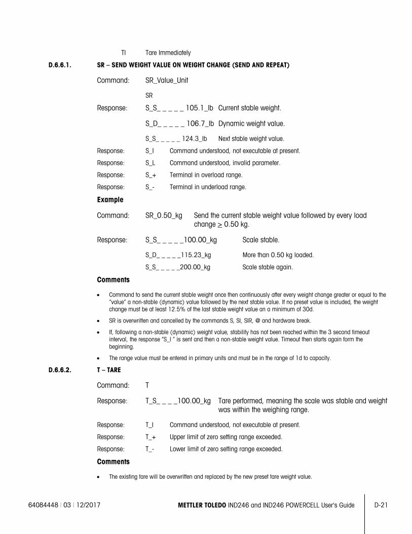
64084448 | 03 | 12/2017 METTLER TOLEDO IND246 and IND246 POWERCELL User's Guide D-21
TI Tare Immediately
D.6.6.1. SR – SEND WEIGHT VALUE ON WEIGHT CHANGE (SEND AND REPEAT)
Command: SR_Value_Unit
SR
Response: S_S_ _ _ _ _ 105.1_lb Current stable weight.
S_D_ _ _ _ _ 106.7_lb Dynamic weight value.
S_S_ _ _ _ _ 124.3_lb Next stable weight value.
Response: S_I Command understood, not executable at present.
Response: S_L Command understood, invalid parameter.
Response: S_+ Terminal in overload range.
Response: S_- Terminal in underload range.
Example
Command: SR_0.50_kg Send the current stable weight value followed by every load change > 0.50 kg.
Response: S_S_ _ _ _ _100.00_kg Scale stable.
S_D_ _ _ _ _115.23_kg More than 0.50 kg loaded.
S_S_ _ _ _ _200.00_kg Scale stable again.
Comments
• Command to send the current stable weight once then continuously after every weight change greater or equal to the “value” a non-stable (dynamic) value followed by the next stable value. If no preset value is included, the weight change must be at least 12.5% of the last stable weight value an a minimum of 30d.
• SR is overwritten and cancelled by the commands S, SI, SIR, @ and hardware break.
• If, following a non-stable (dynamic) weight value, stability has not been reached within the 3 second timeout interval, the response “S_I “ is sent and then a non-stable weight value. Timeout then starts again form the beginning.
• The range value must be entered in primary units and must be in the range of 1d to capacity.
D.6.6.2. T – TARE
Command: T
Response: T_S_ _ _ _100.00_kg Tare performed, meaning the scale was stable and weight was within the weighing range.
Response: T_I Command understood, not executable at present.
Response: T_+ Upper limit of zero setting range exceeded.
Response: T_- Lower limit of zero setting range exceeded.
Comments
• The existing tare will be overwritten and replaced by the new preset tare weight value.
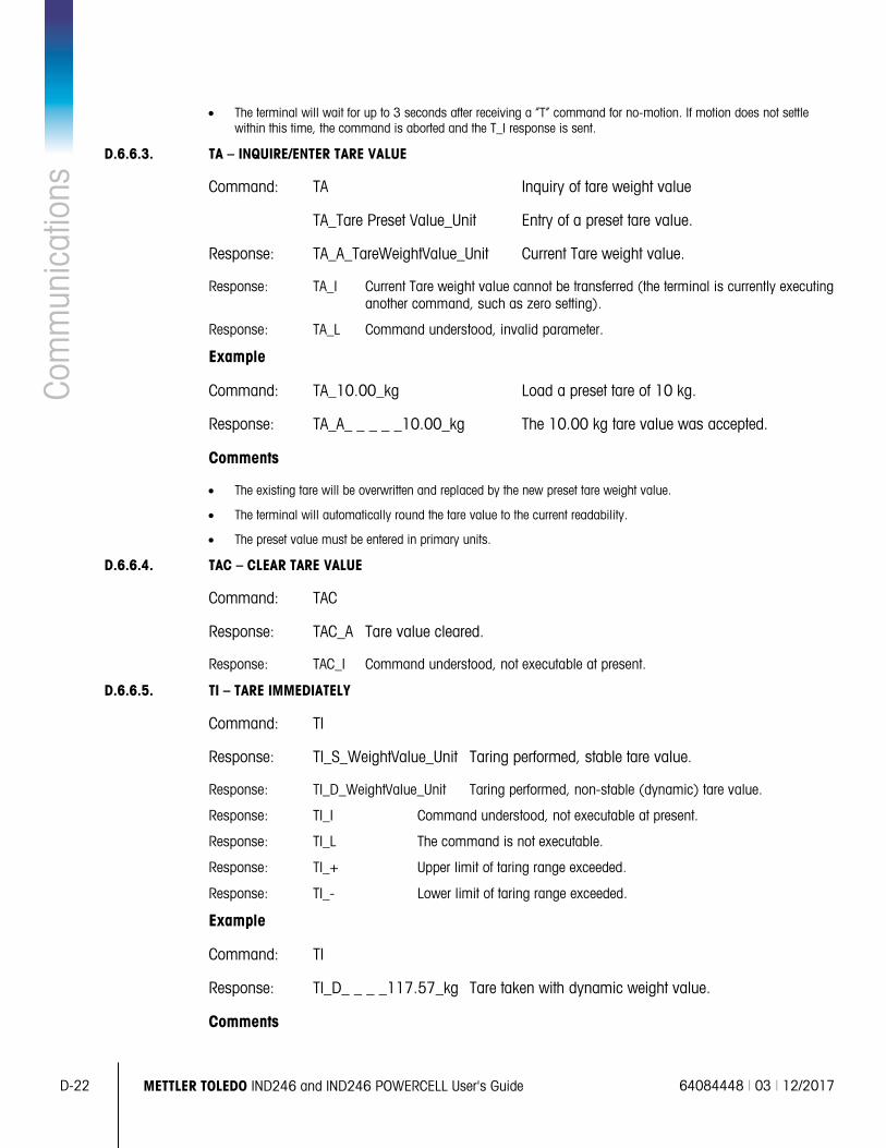
D-22 METTLER TOLEDO IND246 and IND246 POWERCELL User's Guide 64084448 | 03 | 12/2017
Com
mun
icat
ions
• The terminal will wait for up to 3 seconds after receiving a “T” command for no-motion. If motion does not settle
within this time, the command is aborted and the T_I response is sent.
D.6.6.3. TA – INQUIRE/ENTER TARE VALUE
Command: TA Inquiry of tare weight value
TA_Tare Preset Value_Unit Entry of a preset tare value.
Response: TA_A_TareWeightValue_Unit Current Tare weight value.
Response: TA_I Current Tare weight value cannot be transferred (the terminal is currently executing another command, such as zero setting).
Response: TA_L Command understood, invalid parameter.
Example
Command: TA_10.00_kg Load a preset tare of 10 kg.
Response: TA_A_ _ _ _ _10.00_kg The 10.00 kg tare value was accepted.
Comments
• The existing tare will be overwritten and replaced by the new preset tare weight value.
• The terminal will automatically round the tare value to the current readability.
• The preset value must be entered in primary units.
D.6.6.4. TAC – CLEAR TARE VALUE
Command: TAC
Response: TAC_A Tare value cleared.
Response: TAC_I Command understood, not executable at present.
D.6.6.5. TI – TARE IMMEDIATELY
Command: TI
Response: TI_S_WeightValue_Unit Taring performed, stable tare value.
Response: TI_D_WeightValue_Unit Taring performed, non-stable (dynamic) tare value.
Response: TI_I Command understood, not executable at present.
Response: TI_L The command is not executable.
Response: TI_+ Upper limit of taring range exceeded.
Response: TI_- Lower limit of taring range exceeded.
Example
Command: TI
Response: TI_D_ _ _ _117.57_kg Tare taken with dynamic weight value.
Comments
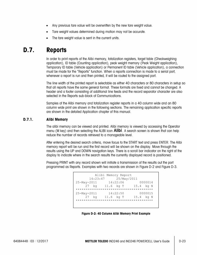
64084448 | 03 | 12/2017 METTLER TOLEDO IND246 and IND246 POWERCELL User's Guide D-23
• Any previous tare value will be overwritten by the new tare weight value.
• Tare weight values determined during motion may not be accurate.
• The tare weight value is sent in the current units.
D.7. Reports In order to print reports of the Alibi memory, totalization registers, target table (Checkweighing application), ID table (Counting application), peak weight memory (Peak Weight application), Temporary ID table (Vehicle application) or Permanent ID table (Vehicle application), a connection must be made for the “Reports” function. When a reports connection is made to a serial port, whenever a report is run and then printed, it will be routed to the assigned port.
The line width of the printed report is selectable as either 40 characters or 80 characters in setup so that all reports have the same general format. These formats are fixed and cannot be changed. A header and a footer consisting of additional line feeds and the record separator character are also selected in the Reports sub-block of Communications.
Samples of the Alibi memory and totalization register reports in a 40 column wide and an 80 column wide print are shown in the following sections. The remaining application specific reports are shown in the detailed Application chapter of this manual.
D.7.1. Alibi Memory
The alibi memory can be viewed and printed. Alibi memory is viewed by accessing the Operator menu (M key) and then selecting the ALIBI icon . A search screen is shown that can help reduce the number of records retrieved to a manageable level.
After entering the desired search criteria, move focus to the START text and press ENTER. The Alibi memory report will be run and the first record will be shown on the display. Move through the results using the UP and DOWN navigation keys. There is a scroll bar indicator on the right of the display to indicate where in the search results the currently displayed record is positioned.
Pressing PRINT with any record shown will initiate a transmission of the results out the port programmed as Reports. Examples with two records are shown in Figure D-2 and Figure D-3.
Figure D-2: 40 Column Alibi Memory Print Example
Alibi Memory Report 14:23:47 25/May/2011 25-May-2011 14:22:06 0000014 27 kg 11.6 kg T 15.4 kg N **************************************** 25-May-2011 14:22:50 0000015 27 kg 11.6 kg T 15.4 kg N ****************************************
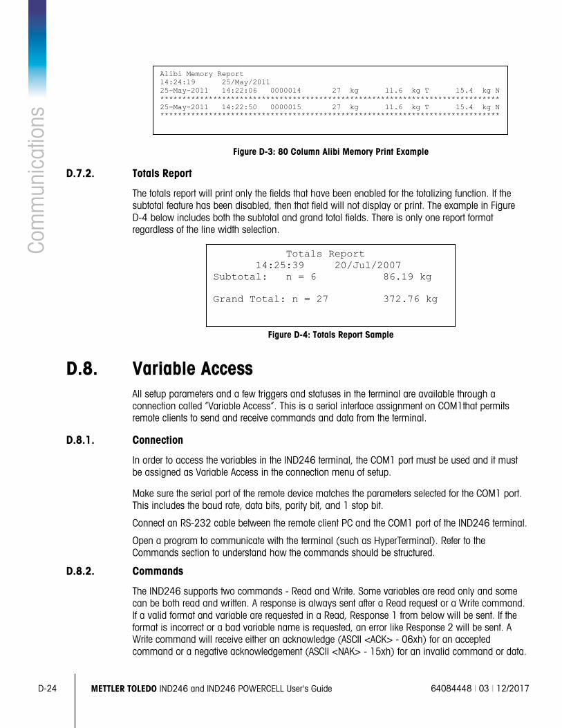
D-24 METTLER TOLEDO IND246 and IND246 POWERCELL User's Guide 64084448 | 03 | 12/2017
Com
mun
icat
ions
Figure D-3: 80 Column Alibi Memory Print Example
D.7.2. Totals Report
The totals report will print only the fields that have been enabled for the totalizing function. If the subtotal feature has been disabled, then that field will not display or print. The example in Figure D-4 below includes both the subtotal and grand total fields. There is only one report format regardless of the line width selection.
Figure D-4: Totals Report Sample
D.8. Variable Access All setup parameters and a few triggers and statuses in the terminal are available through a connection called “Variable Access”. This is a serial interface assignment on COM1that permits remote clients to send and receive commands and data from the terminal.
D.8.1. Connection
In order to access the variables in the IND246 terminal, the COM1 port must be used and it must be assigned as Variable Access in the connection menu of setup.
Make sure the serial port of the remote device matches the parameters selected for the COM1 port. This includes the baud rate, data bits, parity bit, and 1 stop bit.
Connect an RS-232 cable between the remote client PC and the COM1 port of the IND246 terminal.
Open a program to communicate with the terminal (such as HyperTerminal). Refer to the Commands section to understand how the commands should be structured.
D.8.2. Commands
The IND246 supports two commands - Read and Write. Some variables are read only and some can be both read and written. A response is always sent after a Read request or a Write command. If a valid format and variable are requested in a Read, Response 1 from below will be sent. If the format is incorrect or a bad variable name is requested, an error like Response 2 will be sent. A Write command will receive either an acknowledge (ASCII <ACK> - 06xh) for an accepted command or a negative acknowledgement (ASCII <NAK> - 15xh) for an invalid command or data.
Alibi Memory Report 14:24:19 25/May/2011 25-May-2011 14:22:06 0000014 27 kg 11.6 kg T 15.4 kg N ***************************************************************************** 25-May-2011 14:22:50 0000015 27 kg 11.6 kg T 15.4 kg N *****************************************************************************
Totals Report 14:25:39 20/Jul/2007 Subtotal: n = 6 86.19 kg Grand Total: n = 27 372.76 kg
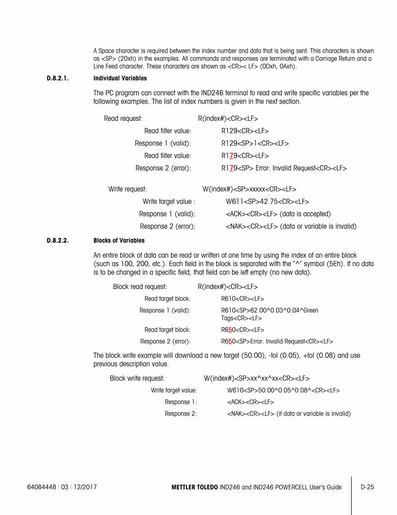
64084448 | 03 | 12/2017 METTLER TOLEDO IND246 and IND246 POWERCELL User's Guide D-25
A Space character is required between the index number and data that is being sent. This characters is shown as <SP> (20xh) in the examples. All commands and responses are terminated with a Carriage Return and a Line Feed character. These characters are shown as <CR>< LF> (0Dxh, 0Axh).
D.8.2.1. Individual Variables
The PC program can connect with the IND246 terminal to read and write specific variables per the following examples. The list of index numbers is given in the next section.
Read request: R(index#)<CR><LF>
Read filter value: R129<CR><LF>
Response 1 (valid): R129<SP>1<CR><LF>
Read filter value: R179<CR><LF>
Response 2 (error): R179<SP> Error: Invalid Request<CR><LF>
Write request: W(index#)<SP>xxxxx<CR><LF>
Write target value : W611<SP>42.75<CR><LF>
Response 1 (valid): <ACK><CR><LF> (data is accepted)
Response 2 (error): <NAK><CR><LF> (data or variable is invalid)
D.8.2.2. Blocks of Variables
An entire block of data can be read or written at one time by using the index of an entire block (such as 100, 200, etc.). Each field in the block is separated with the “^” symbol (5Eh). If no data is to be changed in a specific field, that field can be left empty (no new data).
Block read request: R(index#)<CR><LF>
Read target block: R610<CR><LF>
Response 1 (valid): R610<SP>62.00^0.03^0.04^Green Tags<CR><LF>
Read target block: R650<CR><LF>
Response 2 (error): R650<SP>Error: Invalid Request<CR><LF>
The block write example will download a new target (50.00), -tol (0.05), +tol (0.08) and use previous description value.
Block write request: W(index#)<SP>xx^xx^xx<CR><LF>
Write target value: W610<SP>50.00^0.05^0.08^<CR><LF>
Response 1: <ACK><CR><LF>
Response 2: <NAK><CR><LF> (if data or variable is invalid)
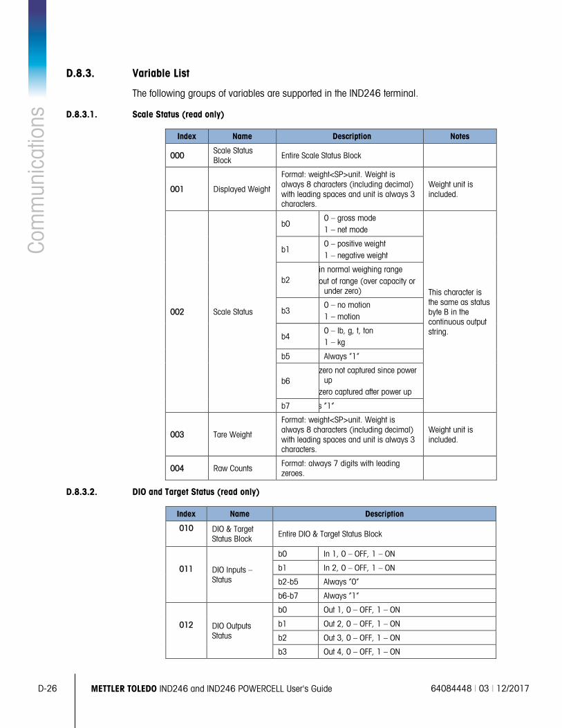
D-26 METTLER TOLEDO IND246 and IND246 POWERCELL User's Guide 64084448 | 03 | 12/2017
Com
mun
icat
ions
D.8.3. Variable List
The following groups of variables are supported in the IND246 terminal.
D.8.3.1. Scale Status (read only)
Index Name Description Notes
000 Scale Status Block Entire Scale Status Block
001 Displayed Weight
Format: weight<SP>unit. Weight is always 8 characters (including decimal) with leading spaces and unit is always 3 characters.
Weight unit is included.
002 Scale Status
b0 0 – gross mode 1 – net mode
This character is the same as status byte B in the continuous output string.
b1 0 – positive weight 1 – negative weight
b2 in normal weighing range out of range (over capacity or
under zero)
b3 0 – no motion 1 – motion
b4 0 – lb, g, t, ton 1 – kg
b5 Always “1”
b6 zero not captured since power
up zero captured after power up
b7 s “1”
003 Tare Weight
Format: weight<SP>unit. Weight is always 8 characters (including decimal) with leading spaces and unit is always 3 characters.
Weight unit is included.
004 Raw Counts Format: always 7 digits with leading zeroes.
D.8.3.2. DIO and Target Status (read only)
Index Name Description
010 DIO & Target Status Block Entire DIO & Target Status Block
011 DIO Inputs – Status
b0 In 1, 0 – OFF, 1 – ON
b1 In 2, 0 – OFF, 1 – ON
b2-b5 Always “0”
b6-b7 Always “1”
012 DIO Outputs Status
b0 Out 1, 0 – OFF, 1 – ON
b1 Out 2, 0 – OFF, 1 – ON
b2 Out 3, 0 – OFF, 1 – ON
b3 Out 4, 0 – OFF, 1 – ON
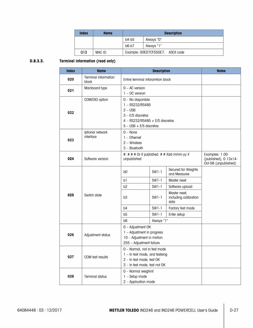
64084448 | 03 | 12/2017 METTLER TOLEDO IND246 and IND246 POWERCELL User's Guide D-27
Index Name Description
b4-b5 Always “0”
b6-b7 Always “1”
013 MAC ID Example: 00E07CF550E7, ASCII code
D.8.3.3. Terminal information (read only)
Index Name Description Notes
020 Terminal information block Entire terminal inforamtion block
021 Mainboard type 0 – AC version
1 – DC version
022
COM/DIO option 0 – No disponible 1 – RS232/RS485 2 – USB 3 – E/S discretas 4 – RS232/RS485 + E/S discretas 5 – USB + E/S discretas
023
Iptional network interface
0 – None 1 – Ethernet 2 – Wireless 3 – Bluetooth
024 Software version #. # # # Or if published. # # Xdd-mmm-yy if unpublished
Examples: 1.00 (published), 0.13x14-Oct-08 (unpublished)
025 Switch state
b0 SW1-1 Secured for Weights and Measures
b1 SW1-1 Master reset b2 SW1-1 Software upload
b3 SW1-1 Master reset, including calibration data
b4 SW1-1 Factory test mode b5 SW1-1 Enter setup b6 Always “1”
026 Adjustment status
0 – Adjustment OK 1 – Adjustment in progress 10 – Adjustment in motion 255 – Adjustment failure
027 COM test results
0 – Normal, not in test mode 1 – In test mode, and testeing 2 – In test mode, test OK 3 – In test mode, test not OK
028 Terminal status 0 – Normal weighint 1 – Setup mode 2 – Application mode
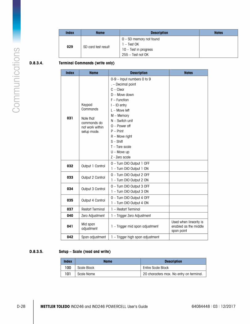
D-28 METTLER TOLEDO IND246 and IND246 POWERCELL User's Guide 64084448 | 03 | 12/2017
Com
mun
icat
ions
Index Name Description Notes
029 SD card test result
0 – SD memory not found 1 – Test OK 10 – Test in progress 255 – Test not OK
D.8.3.4. Terminal Commands (write only)
Index Name Description Notes
031
Keypad Commands
Note that commands do not work within setup mode.
0-9 – Input numbers 0 to 9 . – Decimal point C – Clear D – Move down F – Function I – ID entry L – Move left M – Memory N – Switch unit O – Power off P – Print R – Move right S – Shift T – Tare scale U – Move up Z - Zero scale
032 Output 1 Control 0 – Turn DIO Output 1 OFF 1 – Turn DIO Output 1 ON
033 Output 2 Control 0 – Turn DIO Output 2 OFF 1 – Turn DIO Output 2 ON
034 Output 3 Control 0 – Turn DIO Output 3 OFF 1 – Turn DIO Output 3 ON
035 Output 4 Control 0 – Turn DIO Output 4 OFF 1 – Turn DIO Output 4 ON
037 Restart Terminal 1 – Restart Terminal
040 Zero Adjustment 1 – Trigger Zero Adjustment
041 Mid span adjustment
1 – Trigger mid span adjustment Used when linearity is enabled as the middle span point
042 Span adjustment 1 – Trigger high span adjustment
D.8.3.5. Setup – Scale (read and write)
Index Name Description
100 Scale Block Entire Scale Block
101 Scale Name 20 characters max. No entry on terminal.
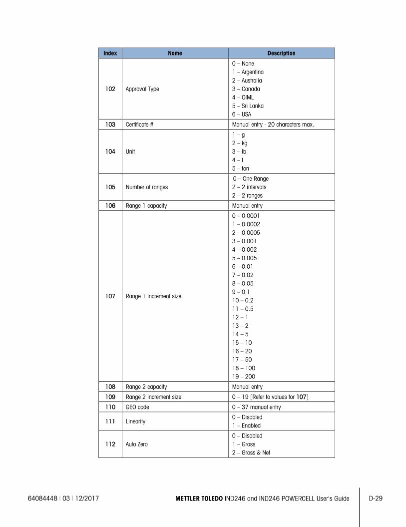
64084448 | 03 | 12/2017 METTLER TOLEDO IND246 and IND246 POWERCELL User's Guide D-29
Index Name Description
102 Approval Type
0 – None 1 – Argentina 2 – Australia 3 – Canada 4 – OIML 5 – Sri Lanka 6 – USA
103 Certificate # Manual entry - 20 characters max.
104 Unit
1 – g 2 – kg 3 – lb 4 – t 5 – ton
105 Number of ranges 0 – One Range 2 – 2 intervals 2 – 2 ranges
106 Range 1 capacity Manual entry
107 Range 1 increment size
0 – 0.0001 1 – 0.0002 2 – 0.0005 3 – 0.001 4 – 0.002 5 – 0.005 6 – 0.01 7 – 0.02 8 – 0.05 9 – 0.1 10 – 0.2 11 – 0.5 12 – 1 13 – 2 14 – 5 15 – 10 16 – 20 17 – 50 18 – 100 19 – 200
108 Range 2 capacity Manual entry
109 Range 2 increment size 0 – 19 [Refer to values for 107]
110 GEO code 0 – 37 manual entry
111 Linearity 0 – Disabled 1 – Enabled
112 Auto Zero 0 – Disabled 1 – Gross 2 – Gross & Net
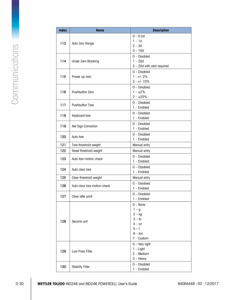
D-30 METTLER TOLEDO IND246 and IND246 POWERCELL User's Guide 64084448 | 03 | 12/2017
Com
mun
icat
ions
Index Name Description
113 Auto Zero Range
0 – 0.5d 1 – 1d 2 – 3d 3 – 10d
114 Under Zero Blanking 0 – Disabled 1 – 20d 2 – 20d with zero required
115 Power up zero 0 – Disabled 1 - +/- 2% 2 - +/- 10%
116 Pushbutton Zero 0 – Disabled 1 – ±2% 2 – ±20%
117 Pushbutton Tare 0 – Disabled 1 – Enabled
118 Keyboard tare 0 – Disabled 1 – Enabled
119 Net Sign Correction 0 – Disabled 1 – Enabled
120 Auto tare 0 – Disabled 1 – Enabled
121 Tare threshold weight Manual entry
122 Reset threshold weight Manual entry
123 Auto tare motion check 0 – Disabled 1 – Enabled
124 Auto clear tare 0 – Disabled 1 – Enabled
125 Clear threshold weight Manual entry
126 Auto clear tare motion check 0 – Disabled 1 – Enabled
127 Clear after print 0 – Disabled 1 – Enabled
128 Second unit
0 – None 1 – g 2 – kg 3 – lb 4 – oz 5 – t 6 – ton 7 – Custom
129 Low Pass Filter
0 – Very light 1 – Light 2 – Medium 3 – Heavy
130 Stability Filter 0 – Disabled 1 – Enabled
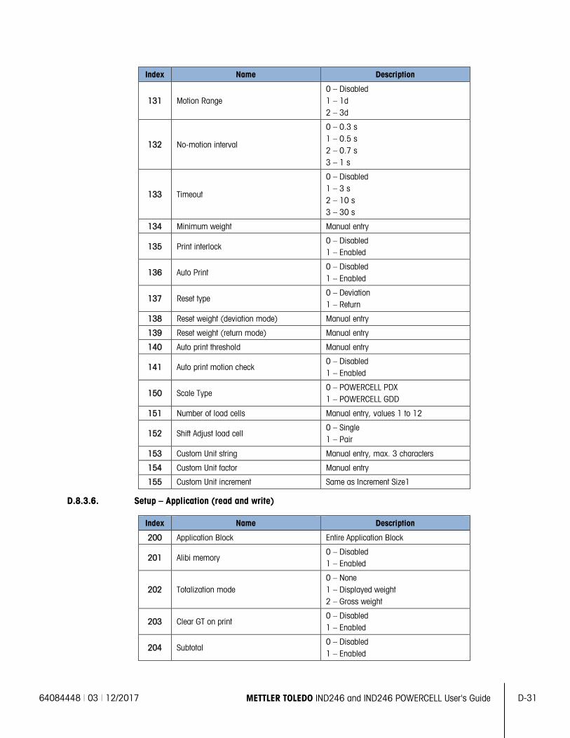
64084448 | 03 | 12/2017 METTLER TOLEDO IND246 and IND246 POWERCELL User's Guide D-31
Index Name Description
131 Motion Range 0 – Disabled 1 – 1d 2 – 3d
132 No-motion interval
0 – 0.3 s 1 – 0.5 s 2 – 0.7 s 3 – 1 s
133 Timeout
0 – Disabled 1 – 3 s 2 – 10 s 3 – 30 s
134 Minimum weight Manual entry
135 Print interlock 0 – Disabled 1 – Enabled
136 Auto Print 0 – Disabled 1 – Enabled
137 Reset type 0 – Deviation 1 – Return
138 Reset weight (deviation mode) Manual entry
139 Reset weight (return mode) Manual entry
140 Auto print threshold Manual entry
141 Auto print motion check 0 – Disabled 1 – Enabled
150 Scale Type 0 – POWERCELL PDX 1 – POWERCELL GDD
151 Number of load cells Manual entry, values 1 to 12
152 Shift Adjust load cell 0 – Single 1 – Pair
153 Custom Unit string Manual entry, max. 3 characters
154 Custom Unit factor Manual entry
155 Custom Unit increment Same as Increment Size1
D.8.3.6. Setup – Application (read and write)
Index Name Description
200 Application Block Entire Application Block
201 Alibi memory 0 – Disabled 1 – Enabled
202 Totalization mode 0 – None 1 – Displayed weight 2 – Gross weight
203 Clear GT on print 0 – Disabled 1 – Enabled
204 Subtotal 0 – Disabled 1 – Enabled
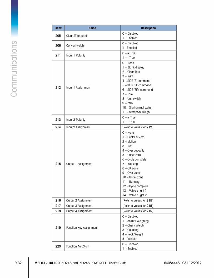
D-32 METTLER TOLEDO IND246 and IND246 POWERCELL User's Guide 64084448 | 03 | 12/2017
Com
mun
icat
ions
Index Name Description
205 Clear ST on print 0 – Disabled 1 – Enabled
206 Convert weight 0 – Disabled 1 - Enabled
211 Input 1 Polarity 0 – + True 1 – - True
212 Input 1 Assignment
0 – None 1 – Blank display 2 – Clear Tare 3 – Print 4 – SICS ‘S’ command 5 – SICS ‘SI’ command 6 – SICS ‘SIR’ command 7 – Tare 8 – Unit switch 9 – Zero 10 – Start animal weigh 11 – Start peak weigh
213 Input 2 Polarity 0 – + True 1 – - True
214 Input 2 Assignment [Refer to values for 212]
215 Output 1 Assignment
0 – None 1 – Center of Zero 2 – Motion 3 – Net 4 – Over capacity 5 – Under Zero 6 – Cycle complete 7 – Working 8 – OK zone 9 – Over zone 10 – Under zone 11 – Running 12 – Cycle complete 13 – Vehicle light 1 14 – Vehicle light 2
216 Output 2 Assignment [Refer to values for 215]
217 Output 3 Assignment [Refer to values for 215]
218 Output 4 Assignment [Refer to values for 215]
219 Function Key Assignment
0 – Disabled 1 – Animal Weighing 2 – Check Weigh 3 – Counting 4 – Peak Weight 5 – Vehicle
220 Function AutoStart 0 – Disabled 1 – Enabled
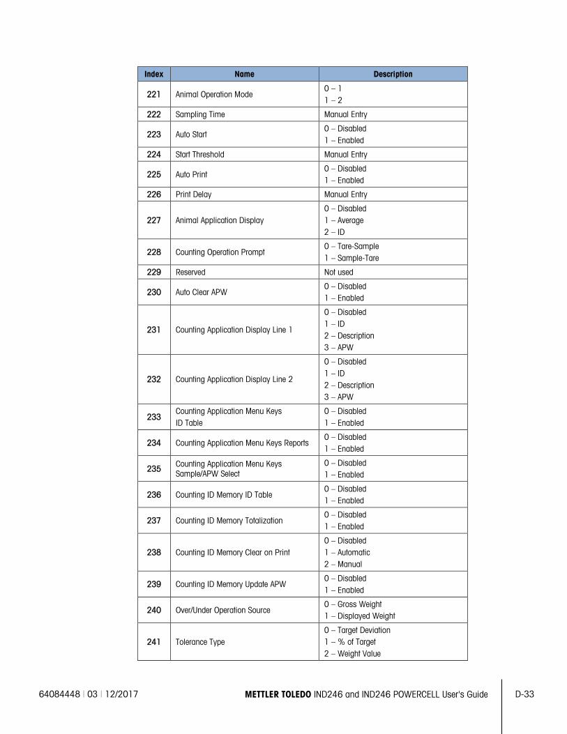
64084448 | 03 | 12/2017 METTLER TOLEDO IND246 and IND246 POWERCELL User's Guide D-33
Index Name Description
221 Animal Operation Mode 0 – 1 1 – 2
222 Sampling Time Manual Entry
223 Auto Start 0 – Disabled 1 – Enabled
224 Start Threshold Manual Entry
225 Auto Print 0 – Disabled 1 – Enabled
226 Print Delay Manual Entry
227 Animal Application Display 0 – Disabled 1 – Average 2 – ID
228 Counting Operation Prompt 0 – Tare-Sample 1 – Sample-Tare
229 Reserved Not used
230 Auto Clear APW 0 – Disabled 1 – Enabled
231 Counting Application Display Line 1
0 – Disabled 1 – ID 2 – Description 3 – APW
232 Counting Application Display Line 2
0 – Disabled 1 – ID 2 – Description 3 – APW
233 Counting Application Menu Keys ID Table
0 – Disabled 1 – Enabled
234 Counting Application Menu Keys Reports 0 – Disabled 1 – Enabled
235 Counting Application Menu Keys Sample/APW Select
0 – Disabled 1 – Enabled
236 Counting ID Memory ID Table 0 – Disabled 1 – Enabled
237 Counting ID Memory Totalization 0 – Disabled 1 – Enabled
238 Counting ID Memory Clear on Print 0 – Disabled 1 – Automatic 2 – Manual
239 Counting ID Memory Update APW 0 – Disabled 1 – Enabled
240 Over/Under Operation Source 0 – Gross Weight 1 – Displayed Weight
241 Tolerance Type 0 – Target Deviation 1 – % of Target 2 – Weight Value
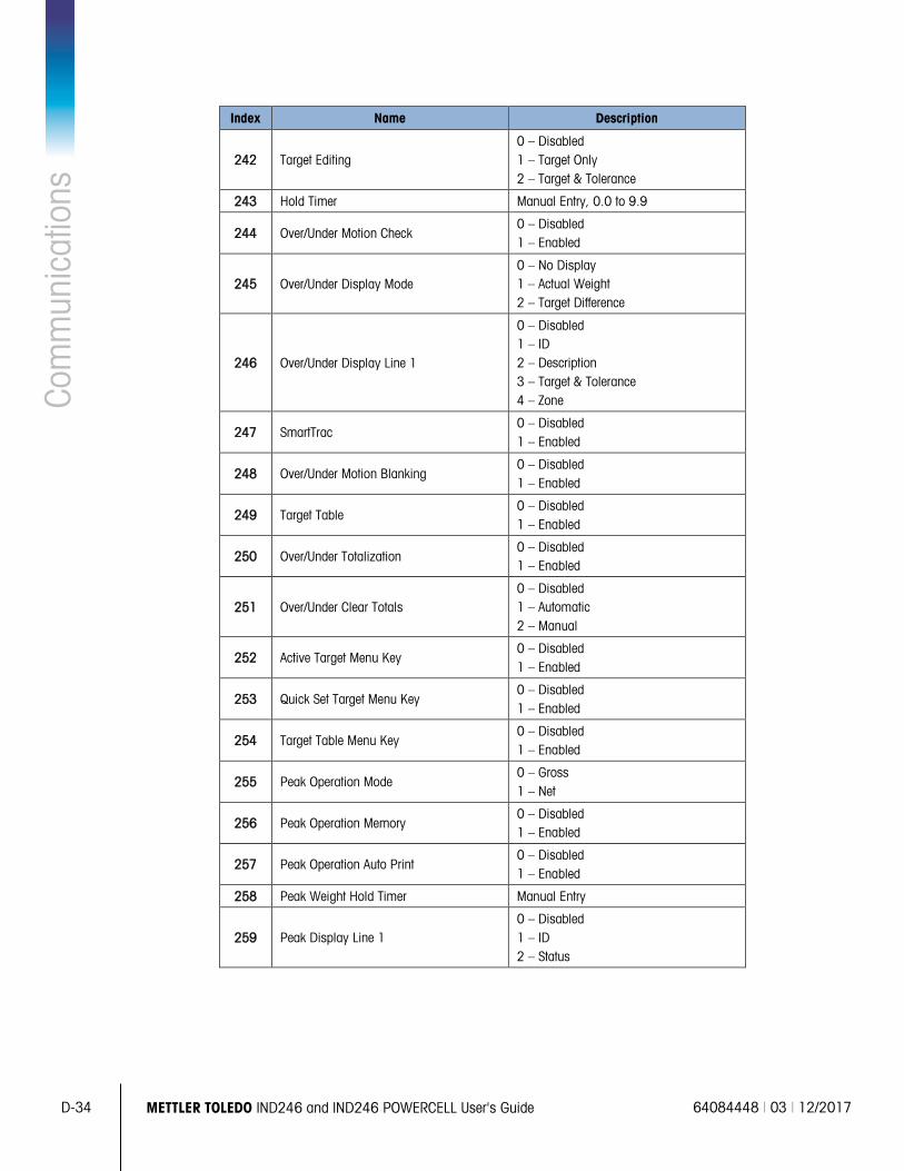
D-34 METTLER TOLEDO IND246 and IND246 POWERCELL User's Guide 64084448 | 03 | 12/2017
Com
mun
icat
ions
Index Name Description
242 Target Editing 0 – Disabled 1 – Target Only 2 – Target & Tolerance
243 Hold Timer Manual Entry, 0.0 to 9.9
244 Over/Under Motion Check 0 – Disabled 1 – Enabled
245 Over/Under Display Mode 0 – No Display 1 – Actual Weight 2 – Target Difference
246 Over/Under Display Line 1
0 – Disabled 1 – ID 2 – Description 3 – Target & Tolerance 4 – Zone
247 SmartTrac 0 – Disabled 1 – Enabled
248 Over/Under Motion Blanking 0 – Disabled 1 – Enabled
249 Target Table 0 – Disabled 1 – Enabled
250 Over/Under Totalization 0 – Disabled 1 – Enabled
251 Over/Under Clear Totals 0 – Disabled 1 – Automatic 2 – Manual
252 Active Target Menu Key 0 – Disabled 1 – Enabled
253 Quick Set Target Menu Key 0 – Disabled 1 – Enabled
254 Target Table Menu Key 0 – Disabled 1 – Enabled
255 Peak Operation Mode 0 – Gross 1 – Net
256 Peak Operation Memory 0 – Disabled 1 – Enabled
257 Peak Operation Auto Print 0 – Disabled 1 – Enabled
258 Peak Weight Hold Timer Manual Entry
259 Peak Display Line 1 0 – Disabled 1 – ID 2 – Status
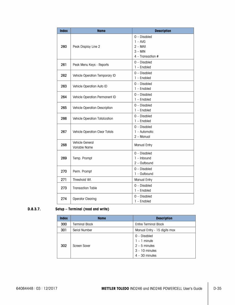
64084448 | 03 | 12/2017 METTLER TOLEDO IND246 and IND246 POWERCELL User's Guide D-35
Index Name Description
260 Peak Display Line 2
0 – Disabled 1 – AVG 2 – MAX 3 – MIN 4 – Transaction #
261 Peak Menu Keys - Reports 0 – Disabled 1 – Enabled
262 Vehicle Operation Temporary ID 0 – Disabled 1 – Enabled
263 Vehicle Operation Auto ID 0 – Disabled 1 – Enabled
264 Vehicle Operation Permanent ID 0 – Disabled 1 – Enabled
265 Vehicle Operation Description 0 – Disabled 1 – Enabled
266 Vehicle Operation Totalization 0 – Disabled 1 – Enabled
267 Vehicle Operation Clear Totals 0 – Disabled 1 – Automatic 2 – Manual
268 Vehicle General Variable Name
Manual Entry
269 Temp. Prompt 0 – Disabled 1 – Inbound 2 – Outbound
270 Perm. Prompt 0 – Disabled 1 – Outbound
271 Threshold Wt. Manual Entry
273 Transaction Table 0 – Disabled 1 – Enabled
274 Operator Clearing 0 – Disabled 1 – Enabled
D.8.3.7. Setup – Terminal (read and write)
Index Name Description
300 Terminal Block Entire Terminal Block
301 Serial Number Manual Entry - 15 digits max
302 Screen Saver
0 – Disabled 1 – 1 minute 2 – 5 minutes 3 – 10 minutes 4 – 30 minutes

D-36 METTLER TOLEDO IND246 and IND246 POWERCELL User's Guide 64084448 | 03 | 12/2017
Com
mun
icat
ions
Index Name Description
303 Backlight timeout
0 – Always on 1 – Disabled 2 – 1 minute 3 – 5 minutes 4 – 10 minutes
304 Auto off timer
0 – Disabled 1 – 10 minutes 2 – 30 minutes 3 – 60 minutes
305 System line
0 – Blank 1 – Discrete I/O 2 – Time & Date 3 – DIO and Time & Date
306 Tare display 0 – Disabled 1 – Always 2 – When active
307 Time Format
0 – 12:MM 1 – 12:MM:SS 2 – 24:MM 3 – 24:MM:SS
308 Date format
0 – DD/MM/YY 1 – DD/MMM/YYYY 2 – MM/DD/YY 3 – MMM/DD/YYYY 4 – YY/MM/DD 5 –YYYY/MMM/DD
309 Date field separator
0 - / 1 - - 2 -. 3 – (space) 4 – None
310 Set hour Manual entry
311 Select AM/PM 0 – AM 1 – PM
312 Set minutes Manual entry
313 Set day Manual Entry
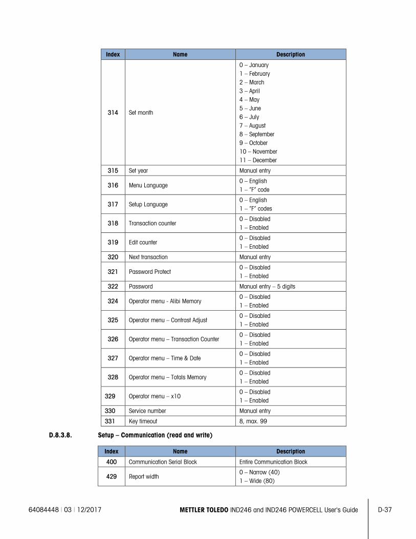
64084448 | 03 | 12/2017 METTLER TOLEDO IND246 and IND246 POWERCELL User's Guide D-37
Index Name Description
314 Set month
0 – January 1 – February 2 – March 3 – April 4 – May 5 – June 6 – July 7 – August 8 – September 9 – October 10 – November 11 – December
315 Set year Manual entry
316 Menu Language 0 – English 1 – “F” code
317 Setup Language 0 – English 1 – “F” codes
318 Transaction counter 0 – Disabled 1 – Enabled
319 Edit counter 0 – Disabled 1 – Enabled
320 Next transaction Manual entry
321 Password Protect 0 – Disabled 1 – Enabled
322 Password Manual entry – 5 digits
324 Operator menu - Alibi Memory 0 – Disabled 1 – Enabled
325 Operator menu – Contrast Adjust 0 – Disabled 1 – Enabled
326 Operator menu – Transaction Counter 0 – Disabled 1 – Enabled
327 Operator menu – Time & Date 0 – Disabled 1 – Enabled
328 Operator menu – Totals Memory 0 – Disabled 1 – Enabled
329 Operator menu – x10 0 – Disabled 1 – Enabled
330 Service number Manual entry
331 Key timeout 8, max. 99
D.8.3.8. Setup – Communication (read and write)
Index Name Description
400 Communication Serial Block Entire Communication Block
429 Report width 0 – Narrow (40) 1 – Wide (80)
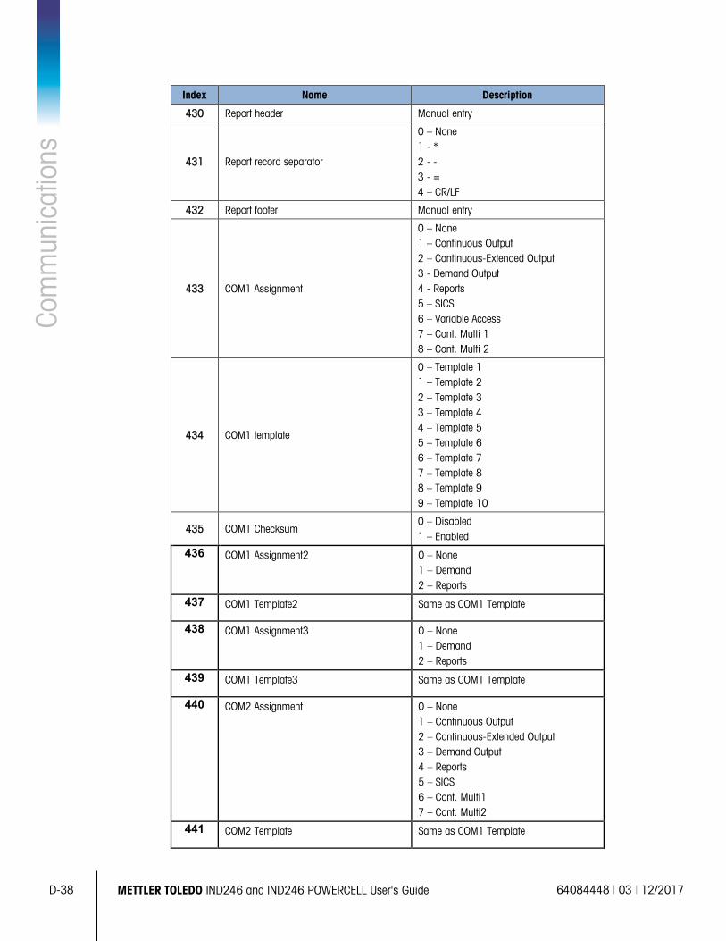
D-38 METTLER TOLEDO IND246 and IND246 POWERCELL User's Guide 64084448 | 03 | 12/2017
Com
mun
icat
ions
Index Name Description
430 Report header Manual entry
431 Report record separator
0 – None 1 - * 2 - - 3 - = 4 – CR/LF
432 Report footer Manual entry
433 COM1 Assignment
0 – None 1 – Continuous Output 2 – Continuous-Extended Output 3 - Demand Output 4 - Reports 5 – SICS 6 – Variable Access 7 – Cont. Multi 1 8 – Cont. Multi 2
434 COM1 template
0 – Template 1 1 – Template 2 2 – Template 3 3 – Template 4 4 – Template 5 5 – Template 6 6 – Template 7 7 – Template 8 8 – Template 9 9 – Template 10
435 COM1 Checksum 0 – Disabled 1 – Enabled
436 COM1 Assignment2 0 – None 1 – Demand 2 – Reports
437 COM1 Template2 Same as COM1 Template
438 COM1 Assignment3 0 – None 1 – Demand 2 – Reports
439 COM1 Template3 Same as COM1 Template
440 COM2 Assignment 0 – None 1 – Continuous Output 2 – Continuous-Extended Output 3 – Demand Output 4 – Reports 5 – SICS 6 – Cont. Multi1 7 – Cont. Multi2
441 COM2 Template Same as COM1 Template
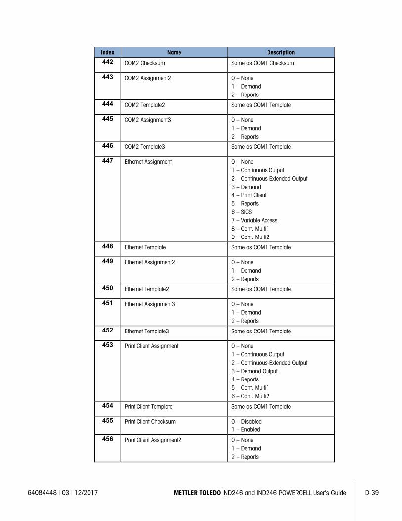
64084448 | 03 | 12/2017 METTLER TOLEDO IND246 and IND246 POWERCELL User's Guide D-39
Index Name Description
442 COM2 Checksum Same as COM1 Checksum
443 COM2 Assignment2 0 – None 1 – Demand 2 – Reports
444 COM2 Template2 Same as COM1 Template
445 COM2 Assignment3 0 – None 1 – Demand 2 – Reports
446 COM2 Template3 Same as COM1 Template
447 Ethernet Assignment 0 – None 1 – Continuous Output 2 – Continuous-Extended Output 3 – Demand 4 – Print Client 5 – Reports 6 – SICS 7 – Variable Access 8 – Cont. Multi1 9 – Cont. Multi2
448 Ethernet Template Same as COM1 Template
449 Ethernet Assignment2 0 – None 1 – Demand 2 – Reports
450 Ethernet Template2 Same as COM1 Template
451 Ethernet Assignment3 0 – None 1 – Demand 2 – Reports
452 Ethernet Template3 Same as COM1 Template
453 Print Client Assignment 0 – None 1 – Continuous Output 2 – Continuous-Extended Output 3 – Demand Output 4 – Reports 5 – Cont. Multi1 6 – Cont. Multi2
454 Print Client Template Same as COM1 Template
455 Print Client Checksum 0 – Disabled 1 – Enabled
456 Print Client Assignment2 0 – None 1 – Demand 2 – Reports
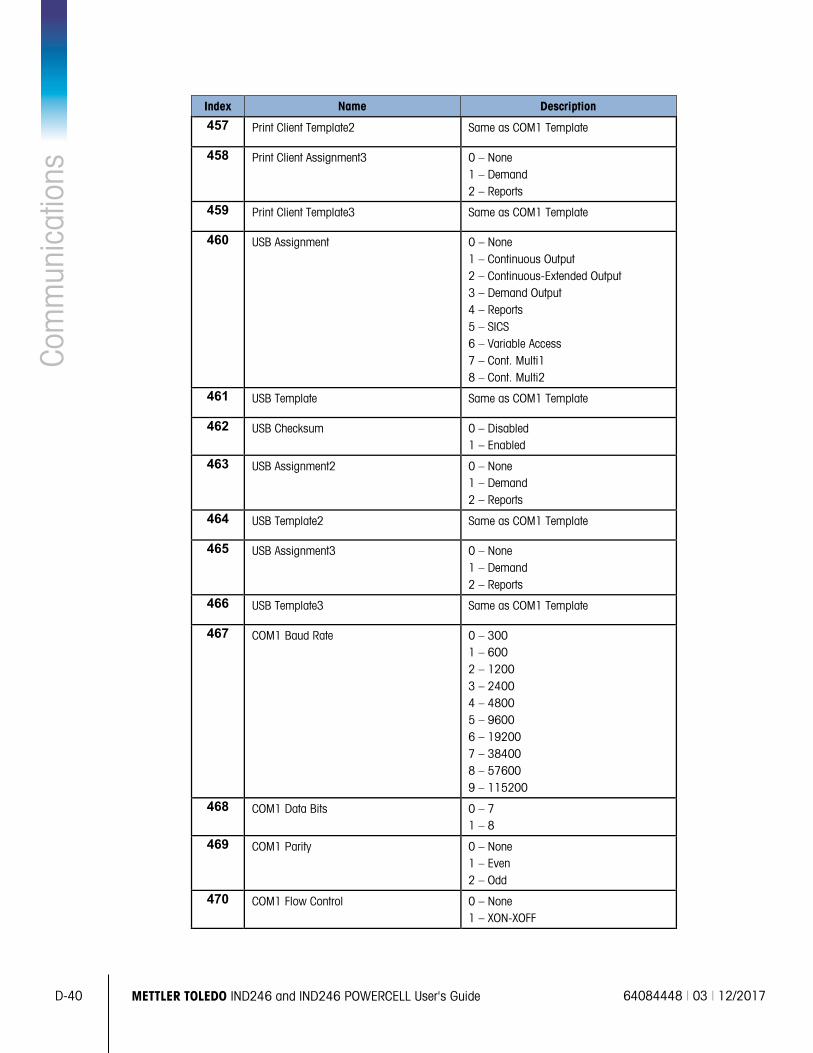
D-40 METTLER TOLEDO IND246 and IND246 POWERCELL User's Guide 64084448 | 03 | 12/2017
Com
mun
icat
ions
Index Name Description
457 Print Client Template2 Same as COM1 Template
458 Print Client Assignment3 0 – None 1 – Demand 2 – Reports
459 Print Client Template3 Same as COM1 Template
460 USB Assignment 0 – None 1 – Continuous Output 2 – Continuous-Extended Output 3 – Demand Output 4 – Reports 5 – SICS 6 – Variable Access 7 – Cont. Multi1 8 – Cont. Multi2
461 USB Template Same as COM1 Template
462 USB Checksum 0 – Disabled 1 – Enabled
463 USB Assignment2 0 – None 1 – Demand 2 – Reports
464 USB Template2 Same as COM1 Template
465 USB Assignment3 0 – None 1 – Demand 2 – Reports
466 USB Template3 Same as COM1 Template
467 COM1 Baud Rate 0 – 300 1 – 600 2 – 1200 3 – 2400 4 – 4800 5 – 9600 6 – 19200 7 – 38400 8 – 57600 9 – 115200
468 COM1 Data Bits 0 – 7 1 – 8
469 COM1 Parity 0 – None 1 – Even 2 – Odd
470 COM1 Flow Control 0 – None 1 – XON-XOFF
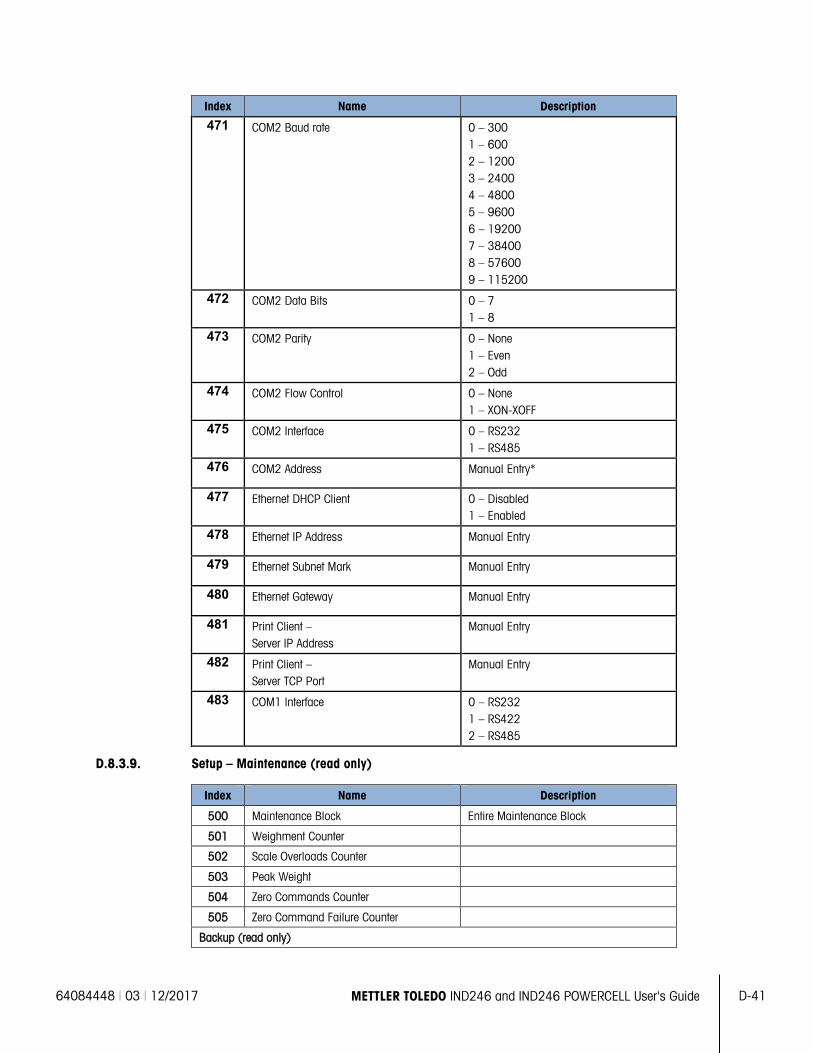
64084448 | 03 | 12/2017 METTLER TOLEDO IND246 and IND246 POWERCELL User's Guide D-41
Index Name Description
471 COM2 Baud rate 0 – 300 1 – 600 2 – 1200 3 – 2400 4 – 4800 5 – 9600 6 – 19200 7 – 38400 8 – 57600 9 – 115200
472 COM2 Data Bits 0 – 7 1 – 8
473 COM2 Parity 0 – None 1 – Even 2 – Odd
474 COM2 Flow Control 0 – None 1 – XON-XOFF
475 COM2 Interface 0 – RS232 1 – RS485
476 COM2 Address Manual Entry*
477 Ethernet DHCP Client 0 – Disabled 1 – Enabled
478 Ethernet IP Address Manual Entry
479 Ethernet Subnet Mark Manual Entry
480 Ethernet Gateway Manual Entry
481 Print Client – Server IP Address
Manual Entry
482 Print Client – Server TCP Port
Manual Entry
483 COM1 Interface 0 – RS232 1 – RS422 2 – RS485
D.8.3.9. Setup – Maintenance (read only)
Index Name Description
500 Maintenance Block Entire Maintenance Block
501 Weighment Counter
502 Scale Overloads Counter
503 Peak Weight
504 Zero Commands Counter
505 Zero Command Failure Counter
Backup (read only)
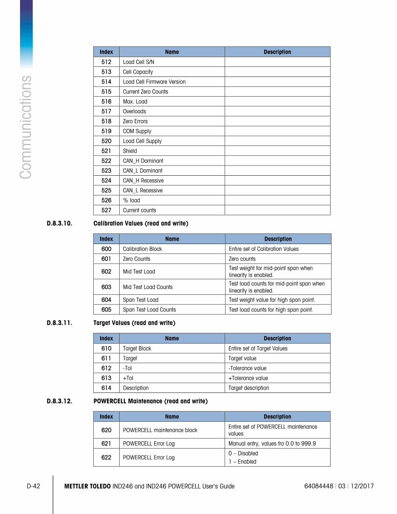
D-42 METTLER TOLEDO IND246 and IND246 POWERCELL User's Guide 64084448 | 03 | 12/2017
Com
mun
icat
ions
Index Name Description
512 Load Cell S/N
513 Cell Capacity
514 Load Cell Firmware Version
515 Current Zero Counts
516 Max. Load
517 Overloads
518 Zero Errors
519 COM Supply
520 Load Cell Supply
521 Shield
522 CAN_H Dominant
523 CAN_L Dominant
524 CAN_H Recessive
525 CAN_L Recessive
526 % load
527 Current counts
D.8.3.10. Calibration Values (read and write)
Index Name Description
600 Calibration Block Entire set of Calibration Values
601 Zero Counts Zero counts
602 Mid Test Load Test weight for mid-point span when linearity is enabled.
603 Mid Test Load Counts Test load counts for mid-point span when linearity is enabled.
604 Span Test Load Test weight value for high span point.
605 Span Test Load Counts Test load counts for high span point.
D.8.3.11. Target Values (read and write)
Index Name Description
610 Target Block Entire set of Target Values
611 Target Target value
612 -Tol -Tolerance value
613 +Tol +Tolerance value
614 Description Target description
D.8.3.12. POWERCELL Maintenance (read and write)
Index Name Description
620 POWERCELL maintenance block Entire set of POWERCELL maintenance values
621 POWERCELL Error Log Manual entry, values fro 0.0 to 999.9
622 POWERCELL Error Log 0 – Disabled 1 – Enabled
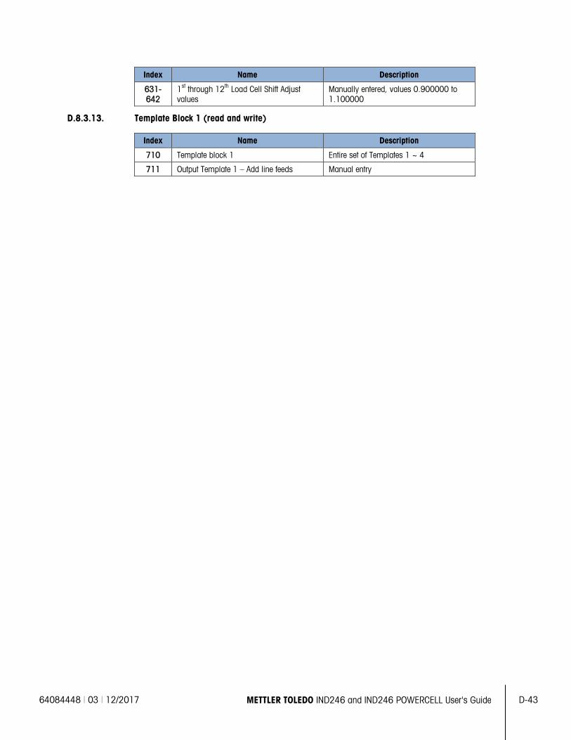
64084448 | 03 | 12/2017 METTLER TOLEDO IND246 and IND246 POWERCELL User's Guide D-43
Index Name Description
631-642
1st through 12th Load Cell Shift Adjust values
Manually entered, values 0.900000 to 1.100000
D.8.3.13. Template Block 1 (read and write)
Index Name Description
710 Template block 1 Entire set of Templates 1 ~ 4
711 Output Template 1 – Add line feeds Manual entry
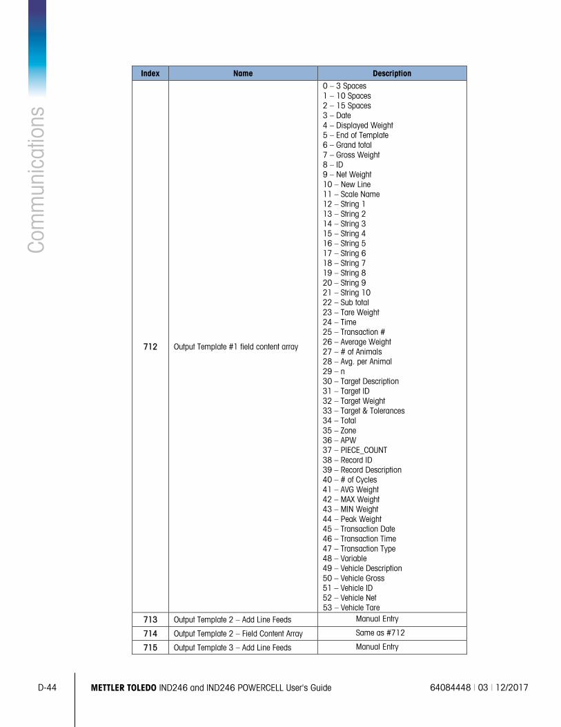
D-44 METTLER TOLEDO IND246 and IND246 POWERCELL User's Guide 64084448 | 03 | 12/2017
Com
mun
icat
ions
Index Name Description
712 Output Template #1 field content array
0 – 3 Spaces 1 – 10 Spaces 2 – 15 Spaces 3 – Date 4 – Displayed Weight 5 – End of Template 6 – Grand total 7 – Gross Weight 8 – ID 9 – Net Weight 10 – New Line 11 – Scale Name 12 – String 1 13 – String 2 14 – String 3 15 – String 4 16 – String 5 17 – String 6 18 – String 7 19 – String 8 20 – String 9 21 – String 10 22 – Sub total 23 – Tare Weight 24 – Time 25 – Transaction # 26 – Average Weight 27 – # of Animals 28 – Avg. per Animal 29 – n 30 – Target Description 31 – Target ID 32 – Target Weight 33 – Target & Tolerances 34 – Total 35 – Zone 36 – APW 37 – PIECE_COUNT 38 – Record ID 39 – Record Description 40 – # of Cycles 41 – AVG Weight 42 – MAX Weight 43 – MIN Weight 44 – Peak Weight 45 – Transaction Date 46 – Transaction Time 47 – Transaction Type 48 – Variable 49 – Vehicle Description 50 – Vehicle Gross 51 – Vehicle ID 52 – Vehicle Net 53 – Vehicle Tare
713 Output Template 2 – Add Line Feeds Manual Entry
714 Output Template 2 – Field Content Array Same as #712
715 Output Template 3 – Add Line Feeds Manual Entry
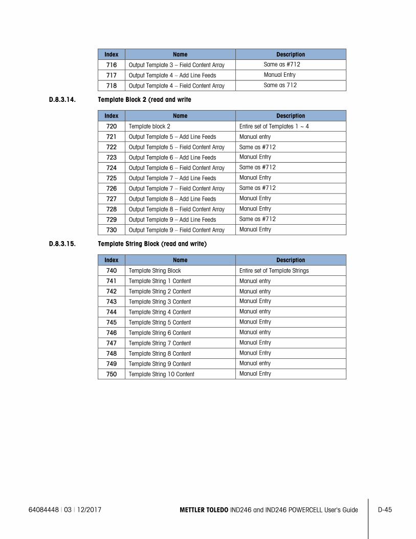
64084448 | 03 | 12/2017 METTLER TOLEDO IND246 and IND246 POWERCELL User's Guide D-45
Index Name Description
716 Output Template 3 – Field Content Array Same as #712
717 Output Template 4 – Add Line Feeds Manual Entry
718 Output Template 4 – Field Content Array Same as 712
D.8.3.14. Template Block 2 (read and write
Index Name Description
720 Template block 2 Entire set of Templates 1 ~ 4
721 Output Template 5 – Add Line Feeds Manual entry
722 Output Template 5 – Field Content Array Same as #712
723 Output Template 6 – Add Line Feeds Manual Entry
724 Output Template 6 – Field Content Array Same as #712
725 Output Template 7 – Add Line Feeds Manual Entry
726 Output Template 7 – Field Content Array Same as #712
727 Output Template 8 – Add Line Feeds Manual Entry
728 Output Template 8 – Field Content Array Manual Entry
729 Output Template 9 – Add Line Feeds Same as #712
730 Output Template 9 – Field Content Array Manual Entry
D.8.3.15. Template String Block (read and write)
Index Name Description
740 Template String Block Entire set of Template Strings
741 Template String 1 Content Manual entry
742 Template String 2 Content Manual entry
743 Template String 3 Content Manual Entry
744 Template String 4 Content Manual entry
745 Template String 5 Content Manual Entry
746 Template String 6 Content Manual entry
747 Template String 7 Content Manual Entry
748 Template String 8 Content Manual Entry
749 Template String 9 Content Manual entry
750 Template String 10 Content Manual Entry
64084448 | 03 | 12/2017 METTLER TOLEDO IND246 and IND246 POWERCELL User's Guide
E-1
E GEO Codes The GEO code feature provided in the IND246 terminal permits calibration readjustment due to changes in elevation or latitude without reapplying test weights. This adjustment assumes a previously accurate calibration was done with the GEO code set properly for that original location and that the GEO code for the new location can be accurately determined. The procedure for using this feature is as follows.
E.1. Original Site Calibration 1. Use the GEO code chart (Table E-1) on the following pages to determine the GEO code for the
current altitude and location at which the scale will be calibrated.
2. Enter that GEO value into the GEO code parameter in setup at Scale > Calibration.
3. Immediately after entering the GEO code, perform a zero and span adjustment using accurate test weights.
4. Exit the setup menu tree.
5. The scale can now be used in its new location.
E.2. New Site GEO Code Adjustment When a terminal is to be reinstalled at a different geographic location, gravitational and altitude changes can be accounted for by following these steps. Note that this procedure is not necessary if an on-site recalibration is performed.
1. Use the GEO code chart (Table E-1) on the following pages to determine the GEO code for the new altitude and location at which the scale will be used.
2. Enter that GEO value into the GEO code parameter in Setup at Scale > Calibration.
3. Immediately after entering the GEO code, exit the setup menu tree. DO NOT perform a normal calibration.
The calibration has now been adjusted for the differences in gravity from the original site of calibration to the new site of use.
Using the GEO code value for calibration adjustment is not as accurate as re-applying certified test weights and re-calibrating the scale in a new location.
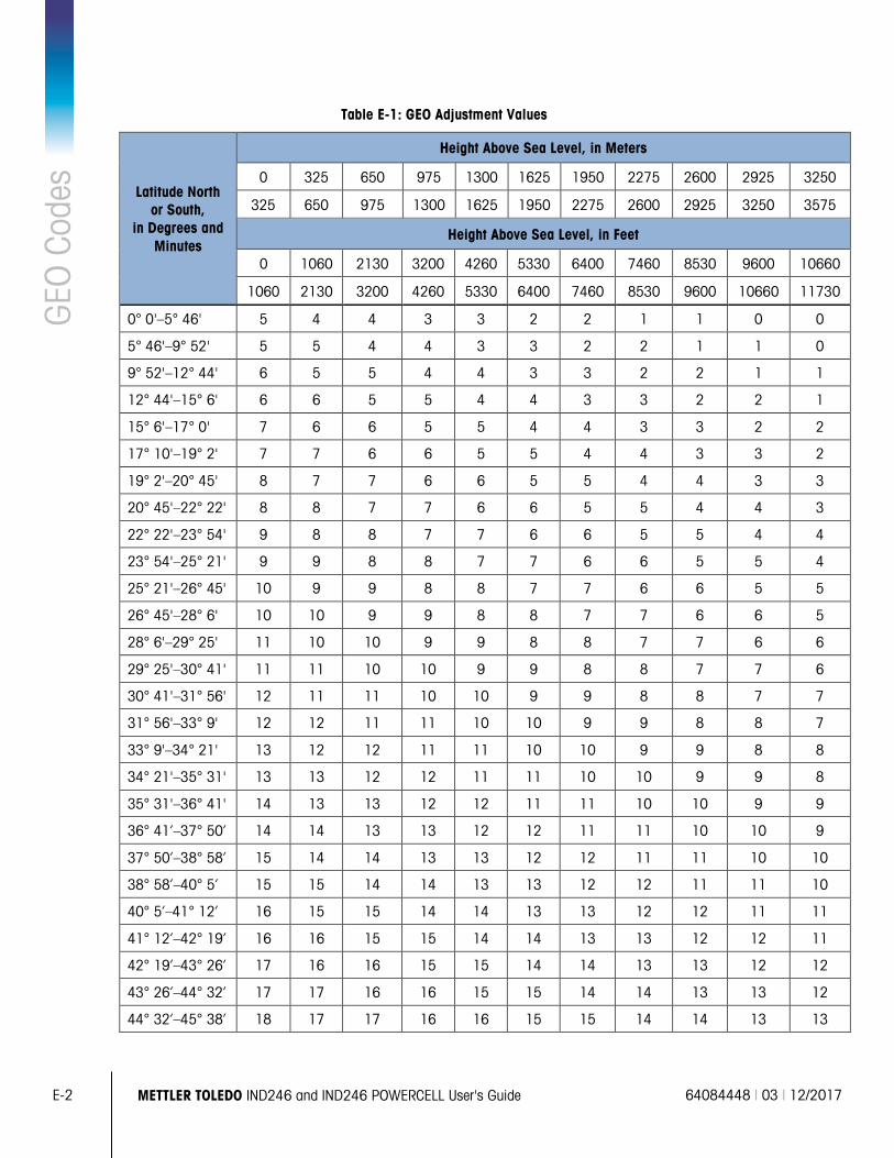
E-2
METTLER TOLEDO IND246 and IND246 POWERCELL User's Guide 64084448 | 03 | 12/2017
GEO
Cod
es
Table E-1: GEO Adjustment Values
Latitude North or South,
in Degrees and Minutes
Height Above Sea Level, in Meters
0 325 650 975 1300 1625 1950 2275 2600 2925 3250
325 650 975 1300 1625 1950 2275 2600 2925 3250 3575
Height Above Sea Level, in Feet
0 1060 2130 3200 4260 5330 6400 7460 8530 9600 10660
1060 2130 3200 4260 5330 6400 7460 8530 9600 10660 11730
0° 0'–5° 46' 5 4 4 3 3 2 2 1 1 0 0
5° 46'–9° 52' 5 5 4 4 3 3 2 2 1 1 0
9° 52'–12° 44' 6 5 5 4 4 3 3 2 2 1 1
12° 44'–15° 6' 6 6 5 5 4 4 3 3 2 2 1
15° 6'–17° 0' 7 6 6 5 5 4 4 3 3 2 2
17° 10'–19° 2' 7 7 6 6 5 5 4 4 3 3 2
19° 2'–20° 45' 8 7 7 6 6 5 5 4 4 3 3
20° 45'–22° 22' 8 8 7 7 6 6 5 5 4 4 3
22° 22'–23° 54' 9 8 8 7 7 6 6 5 5 4 4
23° 54'–25° 21' 9 9 8 8 7 7 6 6 5 5 4
25° 21'–26° 45' 10 9 9 8 8 7 7 6 6 5 5
26° 45'–28° 6' 10 10 9 9 8 8 7 7 6 6 5
28° 6'–29° 25' 11 10 10 9 9 8 8 7 7 6 6
29° 25'–30° 41' 11 11 10 10 9 9 8 8 7 7 6
30° 41'–31° 56' 12 11 11 10 10 9 9 8 8 7 7
31° 56'–33° 9' 12 12 11 11 10 10 9 9 8 8 7
33° 9'–34° 21' 13 12 12 11 11 10 10 9 9 8 8
34° 21'–35° 31' 13 13 12 12 11 11 10 10 9 9 8
35° 31'–36° 41' 14 13 13 12 12 11 11 10 10 9 9
36° 41’–37° 50’ 14 14 13 13 12 12 11 11 10 10 9
37° 50’–38° 58’ 15 14 14 13 13 12 12 11 11 10 10
38° 58’–40° 5’ 15 15 14 14 13 13 12 12 11 11 10
40° 5’–41° 12’ 16 15 15 14 14 13 13 12 12 11 11
41° 12’–42° 19’ 16 16 15 15 14 14 13 13 12 12 11
42° 19’–43° 26’ 17 16 16 15 15 14 14 13 13 12 12
43° 26’–44° 32’ 17 17 16 16 15 15 14 14 13 13 12
44° 32’–45° 38’ 18 17 17 16 16 15 15 14 14 13 13
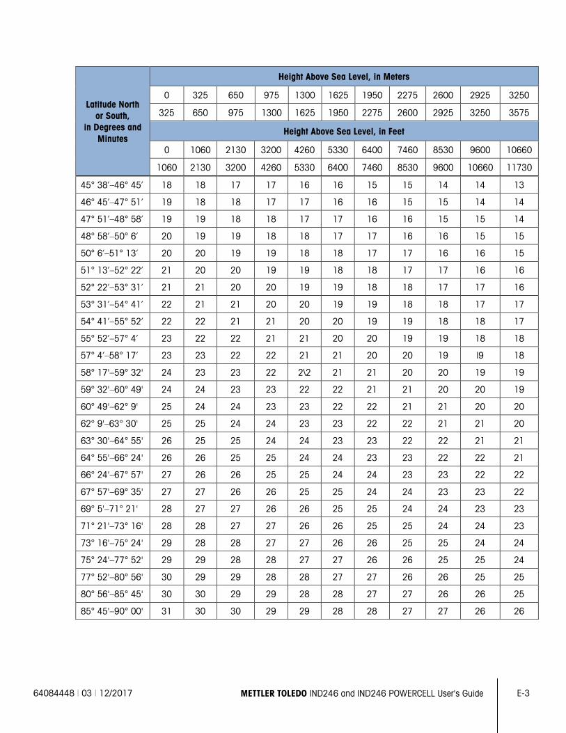
64084448 | 03 | 12/2017 METTLER TOLEDO IND246 and IND246 POWERCELL User's Guide
E-3
Latitude North or South,
in Degrees and Minutes
Height Above Sea Level, in Meters
0 325 650 975 1300 1625 1950 2275 2600 2925 3250
325 650 975 1300 1625 1950 2275 2600 2925 3250 3575
Height Above Sea Level, in Feet
0 1060 2130 3200 4260 5330 6400 7460 8530 9600 10660
1060 2130 3200 4260 5330 6400 7460 8530 9600 10660 11730
45° 38’–46° 45’ 18 18 17 17 16 16 15 15 14 14 13
46° 45’–47° 51’ 19 18 18 17 17 16 16 15 15 14 14
47° 51’–48° 58’ 19 19 18 18 17 17 16 16 15 15 14
48° 58’–50° 6’ 20 19 19 18 18 17 17 16 16 15 15
50° 6’–51° 13’ 20 20 19 19 18 18 17 17 16 16 15
51° 13’–52° 22’ 21 20 20 19 19 18 18 17 17 16 16
52° 22’–53° 31’ 21 21 20 20 19 19 18 18 17 17 16
53° 31’–54° 41’ 22 21 21 20 20 19 19 18 18 17 17
54° 41’–55° 52’ 22 22 21 21 20 20 19 19 18 18 17
55° 52’–57° 4’ 23 22 22 21 21 20 20 19 19 18 18
57° 4’–58° 17’ 23 23 22 22 21 21 20 20 19 l9 18
58° 17'–59° 32' 24 23 23 22 2\2 21 21 20 20 19 19
59° 32'–60° 49' 24 24 23 23 22 22 21 21 20 20 19
60° 49'–62° 9' 25 24 24 23 23 22 22 21 21 20 20
62° 9'–63° 30' 25 25 24 24 23 23 22 22 21 21 20
63° 30'–64° 55' 26 25 25 24 24 23 23 22 22 21 21
64° 55'–66° 24' 26 26 25 25 24 24 23 23 22 22 21
66° 24'–67° 57' 27 26 26 25 25 24 24 23 23 22 22
67° 57'–69° 35' 27 27 26 26 25 25 24 24 23 23 22
69° 5'–71° 21' 28 27 27 26 26 25 25 24 24 23 23
71° 21'–73° 16' 28 28 27 27 26 26 25 25 24 24 23
73° 16'–75° 24' 29 28 28 27 27 26 26 25 25 24 24
75° 24'–77° 52' 29 29 28 28 27 27 26 26 25 25 24
77° 52'–80° 56' 30 29 29 28 28 27 27 26 26 25 25
80° 56'–85° 45' 30 30 29 29 28 28 27 27 26 26 25
85° 45'–90° 00' 31 30 30 29 29 28 28 27 27 26 26

To protect your METTLER TOLEDO product’s future:
Congratulations on choosing the quality and precision of METTLER TOLEDO. Proper use according to these instructions and regular calibration and maintenance by our factory-trained service team ensure dependable and accurate operation, protecting your investment. Contact us about a METTLER TOLEDO service agreement tailored to your needs and budget.
We invite you to register your product at www.mt.com/productregistration so we can contact you about enhancements, updates and important notifications concerning your product.
www.mt.com/IND246 For more information
Mettler-Toledo, LLC 1900 Polaris Parkway Columbus, OH 43240 Phone 800 438 4511 Fax 614 438 4900
© 2017 Mettler-Toledo, LLC 64084448 Rev. 03, 12/2017