Incorporating Very Powerful Structural Analysis And · PDF fileSoftware Packages into Civil...
13
AC 2010-2267: INCORPORATING VERY POWERFUL STRUCTURAL ANALYSIS AND DESIGN SOFTWARE PACKAGES INTO CIVIL ENGINEERING COURSES Mohammad Alhassan, Indiana University Purdue University, Fort Wayne James Welch, Indiana-Purdue University Fort Wayne (IPFW) © American Society for Engineering Education, 2010 Page 15.717.1
Transcript of Incorporating Very Powerful Structural Analysis And · PDF fileSoftware Packages into Civil...
AC 2010-2267: INCORPORATING VERY POWERFUL STRUCTURAL ANALYSISAND DESIGN SOFTWARE PACKAGES INTO CIVIL ENGINEERING COURSES
Mohammad Alhassan, Indiana University Purdue University, Fort Wayne
James Welch, Indiana-Purdue University Fort Wayne (IPFW)
© American Society for Engineering Education, 2010
Page 15.717.1
Incorporating Very Powerful Structural Analysis and Design
Software Packages into Civil Engineering Courses
Abstract
Extensively used in the continuous series of undergraduate structural analysis and design
courses, SAP2000 and ETABS have helped the civil engineering students gain real world
experience with some of the most powerful software packages available to professionals.
Allowing students to learn the software step by step (modeling, analysis, and design) in a
sequential approach through successive interrelated core and elective courses (Structural
Analysis, Reinforced Concrete Design, and Steel Design), supplies the students with the
fundamentals needed to tackle large projects on their own. This paper illuminates the various
learning projects that were given to the students in the courses mentioned above. The paper
continues with a demonstration to a practical application as civil engineering students used
SAP2000 to design a pedestrian bridge for the required capstone senior design course. The
project allowed the students to further explore the various design capabilities of SAP2000 while
moving past the seemingly simple static load conditions, and proceeding to more complex
dynamic and nonlinear analysis of the proposed pedestrian bridge. Using the background from
earlier courses and the online help menu provided by the software, the group was able to
successfully model, analyze, and design the pedestrian bridge in accordance with the AASHTO-
LRFD requirements.
Introduction
The major conundrum of engineering educators is, with every passing year, the level of
technology and practice of engineering increases in its complexity. Accordingly, there will never
be enough time to cover all of the required topics in depth1. However, it is important for
educators to remain current with ongoing trends in their field in order to present a general
overview of technologies that are used in the workplace. Numerous studies have been conducted
to develop new technologies and methods that can be introduced to students in order to allow
them to become successful engineers upon exiting universities. A study performed by Romero
and Museros postulated that, “…computer-based analysis programs and computer software for
design could play an important role in structural engineering education” in a variety of ways, one
of which is using commercial design programs2. Allowing students to gain hands-on experience
with software packages prior to graduation was the second major theme found in another study
that was conducted on practitioners in the field of civil engineering. The first major theme was
that those in the field, “…wanted students to be taught the theory, that they be well grounded in
fundamentals, and that they be able to do the work by hand without the use of the computer.”3
With many recognizing that the effective use of computing is, “…the key to increased individual,
corporate, and national productivity”3, it was decided to incorporate two very powerful structural
analysis and design software packages, SAP2000 and ETABS, into a continuous series of
undergraduate civil engineering courses (structures area) so that the students can gain real world
experience inside the class room. Allowing students to learn the software step by step (modeling,
analysis, and design) in a sequential approach through successive interrelated core and elective
Page 15.717.2
courses (Structural Analysis, Reinforced Concrete Design, and Steel Design), supplies the
students with the fundamentals needed to tackle large projects on their own. Using the software
in a variety of courses allows for the students to further refine these computer skills while they
are at the university, thus fulfilling the ABET outcome of, “…an ability to use the techniques,
skills, and modern engineering tools necessary for engineering practice.”
Structural Analysis Course
Civil engineering students are first introduced to SAP2000 and ETABS in the Structural
Analysis course, a core course in any civil engineering curriculum. SAP2000 is intended for use
on structures such as bridges, dams, stadiums, industrial structures, and buildings. ETABS is a
special version of SAP2000 that is used mainly for buildings4. The power of these software
packages comes from their amazing flexibility; from the simplest design of a two dimensional
frame, to a complicated bridge/building in three dimensions, to the “Bird’s Nest” (Chinese
National) Stadium from the Games of the XXIX Olympiad. Its true strength lays in its various
analysis options that fall in the range of linear and nonlinear, static and dynamic analyses of
three dimensional structures.
Since this is the students’ first experience with the software, two 75 minutes-lectures were given
by the instructor to explain the various features of the software packages and to go over detailed
example. The students were also shown how to use the “Watch and Learn” link on the software
company’s website. Viewing this tutorial allows the students to become more familiar with the
software before they complete the first course project with the following problem statement:
Model and analyze a simply supported truss bridge structure using SAP2000. Show the
structure in different views that display the functional capabilities of SAP2000. Briefly
describe these views and what they are displaying. Such views should include: the
reaction due to dead and live loads, deformed shape, 3-dimensional views of structure,
the releases of each structural member, the axial loading of each member, etc.
After the bridge structure is modeled and analyzed according to the given geometry and loads,
the class explored the various views and outputs that the software is capable of producing.
Figure 1 shows a three dimensional view produced in SAP2000 while Figure 2 is the deformed
view of the bridge structure with the displacements shown at the top. It should be noted that the
deformed shapes given by both SAP2000 and ETABS are magnified to allow for the user to
better visualize the effects the loads on the structure.
Page 15.717.3

Figure 1. Three dimensional view of the bridge structure.
Figure 2. Three dimensional view of the deformed shape of bridge structure.
After obtaining a basic comprehension of computer analysis software through the previous
project, the class is given a more in depth project of modeling a three story building in ETABS
according to the following requirements:
- The dimensions of the building center to center of the exterior columns are 120 ft x 90 ft.
- The height of the first floor = 15 ft, second floor = 15 ft, and third floor = 12 ft
- The columns and beams will be made of steel, start with Auto-select sections WF
- The columns are hinged at the ground level.
- The connection between the beams and columns are pin-pin
- The building will be analyzed for gravity loads
- The Dead load is the self weight of the members plus 20 psf superimposed dead load
- The live load is 80 psf
Page 15.717.4
- The roof live load is 50 psf
- Use the default slab over metal deck system in the ETABS
- Use girders along the column centerlines
- Use floor beams (WF) at 10 ft spacing
- Brace the building in the long direction using concentrically braced frame systems along
the exterior column lines at the end spans from both sides.
- Brace the building in the short direction using concentrically braced frame systems along
the exterior column lines at the mid spans from both sides.
- Make reasonable assumptions for any additional requirements.
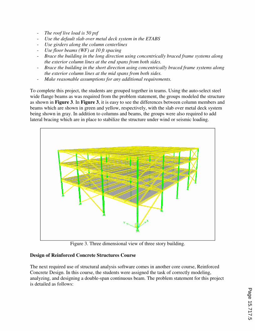
To complete this project, the students are grouped together in teams. Using the auto-select steel
wide flange beams as was required from the problem statement, the groups modeled the structure
as shown in Figure 3. In Figure 3, it is easy to see the differences between column members and
beams which are shown in green and yellow, respectively, with the slab over metal deck system
being shown in gray. In addition to columns and beams, the groups were also required to add
lateral bracing which are in place to stabilize the structure under wind or seismic loading.
Figure 3. Three dimensional view of three story building.
Design of Reinforced Concrete Structures Course
The next required use of structural analysis software comes in another core course, Reinforced
Concrete Design. In this course, the students were assigned the task of correctly modeling,
analyzing, and designing a double-span continuous beam. The problem statement for this project
is detailed as follows:
Page 15.717.5

Use SAP2000/ETABS to design a two span continuous beam with rectangular cross
section to carry a service dead load (without self weight) of 1 k/ft and service live load of
1.2 k/ft. The first span length is 60 ft and the second span length is 40 ft. Design the
beam according to the ACI Code 318. Assume the beam is pin-connected at the left end
and has roller supports between the two spans and at the right end.
Show your analysis and design data from the software. Make sketches to show the cross
section details at the maximum negative and positive moment locations. Use concrete
strength of 6000 psi and Grade 60 steel for all reinforcements. Make reasonable
assumptions for any missing information.
If one without an engineering background was to view this problem statement, the assignment
may appear to be trivial; however the students are not far removed from their structural analysis
course where, in order to calculate the reactions and forces for a statically indeterminate
continuous beam, the only way to analyze the beam would be by using one of the more complex
methods of analysis that the students were taught: either the force method of analysis or one of
the two displacement methods of analysis (slope-deflection equations or moment distribution).
Although each of the students could easily perform these calculations, each of the methods
requires considerable amounts of time to perform all of the steps. After spending only a few
minutes modeling the assigned beam, the students witnessed how powerful SAP2000 was by
eliminating the amount of time required not only to perform one of the methods for a statically
indeterminate beam, but also by circumventing the step-by-step approach for reinforced concrete
design. As long as the software was initialized correctly, all such tasks can be performed
smoothly, with all output being verified by hand calculations. Checking all of the computer
analysis by a series of hand calculations goes right in line with the study conducted by
Abudayyeh, et al.3
Figures 4-6 show screen shots from SAP2000 for the shear and moment
diagrams as well as the deflection curve for the two-span continuous beam.
Figure 4. Shear diagram for continuous beam.
Figure 5. Moment diagram for continuous beam.
Page 15.717.6

Figure 6. Deflection curve for continuous beam.
In addition to analyzing the two-span continuous beam, the students are also given the project of
designing a three story structure using SAP2000/ETABS. This time the students are not only
required to model and analyze the three story building, but they are also required to perform a
complete design using only reinforced concrete for all of the structural members. With the same
project being used in the Structural Analysis course, the problem statement is slightly modified
as so:
- The dimensions of the building center to center of the exterior columns are 120 ft x 90 ft.
- The height of the first floor = 15 ft, second floor = 15 ft, and third floor = 12 ft
- The columns and beams will be made of reinforced concrete
- Use square column sections for the corner columns and rectangular sections for the
perimeter columns
- Use circular columns for all interior columns
- The columns are hinged at the ground level.
- The connection between the beams and columns are pin-pin
- The building will be analyzed for gravity loads only
- The dead load is the self weight of the members plus 20 psf superimposed dead load
- The live load is 80 psf
- The roof live load is 50 psf
- The slab thickness is 6 in.
- Use girders along the column centerlines
- Use floor beams at 10 ft spacing
- Use 4000 psi concrete and Grade 60 steel for the stirrups and longitudinal rebar
- Make reasonable assumptions for any additional requirements.
This project is similar to one that the students may face when they enter the structural
engineering field when a cost analysis must be performed to see whether steel or reinforced
concrete is the economical choice for a given project.
Steel Design Course
In the technical elective course Steel Design, which is typically taken by the students with a
passion for the structural engineering field, the students are given more complex projects in
comparison to those found in the previous courses. The first project was a truss structure while
the second project was the steel design of the same three story residential building that was used
in the two core courses. The problem statement for the steel truss is detailed below with Figure 7
showing the dimensions of the truss that is to be designed.
Page 15.717.7

Use SAP2000/ETABS to design the truss shown below using standard structural steel
sections. Due to constructability issues, use the same T section (A992) for all the top and
bottom chord members. Use the same double angle section (A36) for all vertical
members. Use the same double angle section (A36) for all the diagonal members.
Use the AISC manual to check the software design for the members with the maximum
axial forces (top chord member, bottom chord member, vertical member, and diagonal
member).
Figure 7. Truss used for steel design project.
Once the truss is designed using the software, the students are required to verify the member
sizes by performing a series of hand calculations. Using the fundamentals taught to them through
the lectures given in the Steel Design course, students were given the option of either actually
writing out manually their hand calculations, or they may design a spreadsheet to neatly perform
the same series of calculations. Doing this allows the students to comprehend the fact that they
should not rely blindly on computer output, but must instead understand how the software
completes the design of a given structural system.
After modeling, analyzing, and designing the above truss in SAP2000/ETABS, the students’ next
project is to perform a complete structural design of the same three story residential building
used in both the Structural Analysis and Reinforced Concrete Design courses. Using the same
problem statement that was used for the structure as was used for the second project in
Reinforced Concrete Design; the only major difference is that the design was performed using
steel members. By initially importing structural steel shapes from the software’s built in
database, the groups could define each of the members according to a list of auto shapes that can
be selected during the software’s optimization process. Figure 8 shows the deformed shape of
the three story residential structure under its design loads.
Page 15.717.8

Figure 8. Deformed shape of three-story residential building.
For both of the projects in the Steel Design course, students are required to not only perform the
structural design in either SAP2000 or ETABS, but they are also required to perform hand
calculations on the structural members. Performing these calculations not only verifies that the
students’ model of the structure is accurate, it also goes what practitioners hope for in entry
levels engineers, “…that they be well grounded in fundamentals, and that they be able to do the
work by hand without the use of the computer.”3
Senior Design Project
Using the previous three courses as a foundation, a group of civil engineering students, for their
senior design project, decided to design a pedestrian bridge crossing over a main arterial
roadway which borders the university campus. According to the Department of Engineering, all
senior design capstone projects must adhere to four main objectives. These objectives are:
- To apply knowledge learned in other courses.
- To enhance the thought and planning process
- To expose students to a team design and implementation similar to that encountered in
industry
- To improve the written and oral communication skills of the students.
The proposed design of the bridge, as determined by a decision matrix designed by the students,
was a parabolic arch that had its arched members angled into the centerline of the walkway as is
shown in Figure 9. Although the basics of SAP2000 were previously understood by the students,
Page 15.717.9
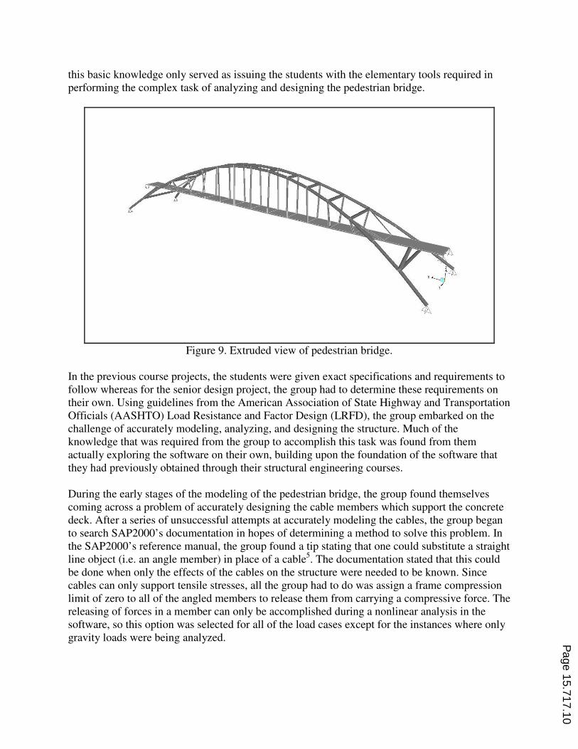
this basic knowledge only served as issuing the students with the elementary tools required in
performing the complex task of analyzing and designing the pedestrian bridge.
Figure 9. Extruded view of pedestrian bridge.
In the previous course projects, the students were given exact specifications and requirements to
follow whereas for the senior design project, the group had to determine these requirements on
their own. Using guidelines from the American Association of State Highway and Transportation
Officials (AASHTO) Load Resistance and Factor Design (LRFD), the group embarked on the
challenge of accurately modeling, analyzing, and designing the structure. Much of the
knowledge that was required from the group to accomplish this task was found from them
actually exploring the software on their own, building upon the foundation of the software that
they had previously obtained through their structural engineering courses.
During the early stages of the modeling of the pedestrian bridge, the group found themselves
coming across a problem of accurately designing the cable members which support the concrete
deck. After a series of unsuccessful attempts at accurately modeling the cables, the group began
to search SAP2000’s documentation in hopes of determining a method to solve this problem. In
the SAP2000’s reference manual, the group found a tip stating that one could substitute a straight
line object (i.e. an angle member) in place of a cable5. The documentation stated that this could
be done when only the effects of the cables on the structure were needed to be known. Since
cables can only support tensile stresses, all the group had to do was assign a frame compression
limit of zero to all of the angled members to release them from carrying a compressive force. The
releasing of forces in a member can only be accomplished during a nonlinear analysis in the
software, so this option was selected for all of the load cases except for the instances where only
gravity loads were being analyzed.
Page 15.717.10

Whereas the previous projects only used dead and live loads, the design of the pedestrian bridge
required additional loading conditions to be analyzed. The two additional load cases that the
group investigated were the wind loading condition as well as loading that would be applied to
the structure from a moving service vehicle load. Applying the wind loading was made relatively
easy through the “Apply Wind Loading” dialog box including in SAP2000. All that was required
was for the group to assign a design wind speed in accordance to code requirements, enter the
angle at which the wind would hit the bridge, and check that only the structural shapes would
have the force of the wind applied to them. A sample of the deformed shape from the wind being
applied perpendicular to the walkway of the bridge is shown in Figure 10.
Figure 10. Deformed view of bridge with wind load applied.
The next major difference in analysis was that the bridge was analyzed with a moving service
vehicle load. In order to apply the load as a moving load, the group had to first assign lanes to the
walkway on the bridge. Once the lanes were defined, the next step was to assign the forces
applied by the service vehicle load as well as the distance between each of these wheel loads. By
assigning lanes for which the moving vehicle load can be applied allowed the group to view
influence lines for the bridge. A sample of an influence line for the joint reaction at the base is
shown in Figure 11. The group was able to display influence lines for reaction, axial, shear,
moment, and torsional forces for all of the members on the structure.
Figure 11. Influence line for joint reaction at base.
Page 15.717.11

The students themselves had to spend countless hours exploring the vast capabilities of
SAP2000, and determine what features and functions would work for this real-world situation.
Thus, the project fulfills the engineering department’s goals for the senior design project,
“…where students apply the knowledge and skills gained in the curriculum to a large-scale,
team-oriented design project”.
Student Survey
After completing some or all of the aforementioned courses, the students were given a survey to
gauge how they felt using computer analysis software helped prepare them for their futures as
civil engineers. Whereas the survey conducted by Abudayyeh, et al.3 focused on practitioners
and educators, the authors wanted to determine how students felt after using these two software
packages throughout their time at the university. Questions asked to the students ranged from,
“In which courses did you learn/use SAP2000/ETABS,” to, “Do you think that
SAP20000/ETABS strengthens your chance of getting a job?”. For the first question, 56% of the
students had taken all three of the courses (Structural Analysis, Reinforced Concrete Design, and
Steel Design), and thus had been exposed to the software packages throughout three different
semesters. With Structural Analysis being a prerequisite course to the other two, all of the
students had been at least exposed to SAP2000/ETABS at the time of the survey.
In addition to the three structural engineering courses, students also have SAP2000/ETABS
available at their disposal for their Senior Design Project. Of the students whom are taking or
have taken the Senior Design course, 100% have used SAP2000/ETABS throughout various
stages of their design projects. The students also responded in saying that using the software
packages in their structural design of their projects has been very helpful (63%), or helpful
(37%). Thus, 100% of those students that have used SAP2000/ETABS in their projects feel that
using the software has at a minimum, been helpful in completing their projects.
Another question that was asked for the students was, “SAP2000/ETABS are very helpful for
better understanding structural engineering concepts?” The majority of the respondents answered
this question either strongly agree (33%) or agree (44%), with 23% answering disagree. With a
broader range of answers on this question, it shows that these structural analysis software
packages should not be used in place of teaching the fundamentals to students, but should instead
be used as a supplement in further enhancing the learning process.
When asked if they recommended using SAP2000 and ETABS in structural engineering courses,
100% of the students either agreed or strongly agreed to the question. Although the vast majority
of students only stated their familiarity with SAP2000 and ETABS was either good (33%) or fair
(44%), 89% of the students felt that having background knowledge of these two software
packages would strengthen their chance of getting a job. It should be noted that the only
respondent to answer this question “Neutral” stated that, “I think it would help for students
pursuing structural engineering, but I am not".
In addition to the previously discussed survey, all engineering students are required to complete
two assessments of each course: one rating the course learning outcomes, and the other verifying
Page 15.717.12

that the ABET outcomes for the courses were achieved. For each of the courses in which
SAP2000 and ETABS were incorporated into the curriculum, all students responded that the
ABET outcome of, “…an ability to use the techniques, skills, and modern engineering tools
necessary for engineering practice” was achieved.
Conclusion
Accomplishing these projects successfully will not only refresh the student’s background with
the two software titles, but it can also refresh their comprehension of both structural analysis and
design. It also supplies the students with very powerful tools needed not only to complete a
senior design project successfully, but also to provide confidence while looking for their first job
as the knowledge with a powerful design software packages is very attractive to many employers
in the structural engineering field.
Bibliography
1. Grigg, Neil S., et al. "Integrated Civil Engineering Curriculum: Five-Year Review." Journal of Professional
Issues in Engineering Education & Practice 130.3 (2004): 160-165. Academic Search Premier. EBSCO. Web.
15 Nov. 2009.
2. Romero, Manuel L., and Pedro Museros "Structural Analysis Education through Model Experiments and
Computer Simulation." Journal of Professional Issues in Engineering Education & Practice 128.4 (2002): 170.
Academic Search Premier. EBSCO. Web. 15 Nov. 2009.
3. Abudayyeh, Osama, et al. "Assessment of the Computing Component of Civil Engineering Education." Journal
of Computing in Civil Engineering 18.3 (2004): 187-195. Academic Search Premier. EBSCO. Web. 15 Nov.
2009.
4. “About Computers & Structures, Inc.”. http://www.csiberkeley.com/company_about.html. 7 Aug 2009.
5. Computers and Structures, Inc. CSI Analysis Reference Manual. Berkeley. CSI, 2008.
Page 15.717.13