Incorporating Safety into the Highway Design Process.
31
Incorporating Safety Incorporating Safety into the Highway Design into the Highway Design Process Process
-
date post
21-Dec-2015 -
Category
Documents
-
view
227 -
download
2
Transcript of Incorporating Safety into the Highway Design Process.

Incorporating Safety into the Incorporating Safety into the Highway Design ProcessHighway Design Process

What is Meant by “Safe”?What is Meant by “Safe”?
• Is This Road Safe?

What is Meant by “Safety”?What is Meant by “Safety”?• Is This Road Safe?
– Is a “Yes” or “No” answer sufficient?
– Would your answer change if you were told...• The road averages 1 crash in 10 years? or...• The road averages 100 crashes in 10 years?

Kinds of SafetyKinds of Safety
• Nominal Safety– A road that conforms to the agency’s policy,
guidelines, and warrants is “nominally” safe
– A road either is, or is not, nominally safe
• Substantive Safety– The performance of a roadway, as defined by
its “expected” crash frequency (i.e., long run average)
– Substantive safety is a continuous variable
– Useful to compare one site with “typical” site

Kinds of SafetyKinds of Safety• Safety Comparison (NCHRP Report 480)

Safety-Conscious DesignSafety-Conscious Design
• AASHTO Guidance– “Consistent adherence to minimum [design
criteria] values is not advisable”
– “Minimum design criteria may not ensure adequate levels of safety in all situations”
– “The challenge to the designer is to achieve the highest level of safety within the physical and financial constraints of a project”
• Highway Safety Design and Operations Guide, 1997

Highway CrashesHighway Crashes• Contributing Factors
– Driver • Age, gender, skill, fatigue level, alcohol, etc.
– Vehicle • Type, age, maintenance, etc.
– Environment • Light conditions, weather, precipitation, fog, etc.
– Roadway• Geometric design, traffic control, etc.
• Focus of current research– Geometric design of the roadway
Quantifying SafetyQuantifying Safety
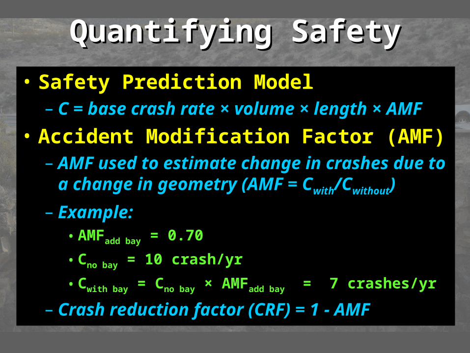
• Safety Prediction Model– C = base crash rate × volume × length × AMF
• Accident Modification Factor (AMF)– AMF used to estimate change in crashes due
to a change in geometry (AMF = Cwith/Cwithout)
– Example: • AMFadd bay = 0.70
• Cno bay = 10 crash/yr
• Cwith bay = Cno bay × AMFadd bay = 7 crashes/yr
– Crash reduction factor (CRF) = 1 - AMF

Crash DataCrash Data• Existing Crash Databases
– Texas Department of Public Safety (DPS)– Local databases
• Severity Scale– K: Fatal– A: Incapacitating injury– B: Non-incapacitating injury– C: Possible injury– PDO: property damage only
• Reporting Threshold – $1000, informally varies among agencies
Research focus

Crash Data VariabilityCrash Data Variability• Examination of Crash History
– Annual crash counts: 2, 3, 1, 1, 7, 5, 2...
– Count in any one year is effectively random
– Variability year to year is LARGE
– So large that...• It is very difficult to determine if the change in count
from year to year is due to a change in geometry, traffic volume, or traffic control device
• It can frustrate efforts to reduce crashes (a change was made but crashes increased)
• It can fool us into thinking a change that we made significantly reduced crashes (when it really did not)
Crash Data VariabilityCrash Data Variability
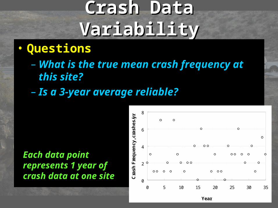
• Questions– What is the true mean crash frequency at
this site?
– Is a 3-year average reliable?
0
2
4
6
8
0 5 10 15 20 25 30 35
Year
Cra
sh
Fre
qu
enc
y, c
ras
he
s/y
r
Each data point represents 1 year of crash data at one site

Crash Data VariabilityCrash Data Variability• Observations
– The average of 3 years (= 6 crashes)...• 2.0 crashes/yr• 0.7 to 4.3 crashes/yr (± 115%)
– The average of 35 years (= 100 crashes)…• 2.8 crashes/yr • 2.2 to 3.3 (± 20%)
0
2
4
6
8
0 5 10 15 20 25 30 35
Year
Cra
sh
Fre
qu
en
cy
, cra
sh
es
/yr
Running Average
Upper Limit (95% confidence interval)
Lower Limit
– One site rarely has enough crashes to yield an average with a precision of ± 20%

Influence of DesignInfluence of Design• Question
– 15 intersections have left-turn bays added
– Research shows bays reduce crashes by 20%
0
2
4
6
8
10
12
14
16
18
0 5 10 15 20 25 30 35
Site
Cra
sh
Fre
qu
en
cy
, cra
sh
es
/yr
0 5 10 15
Before Bay After Bay
Site 4
– What crash frequency do you expect for site 4 after the bay is installed?
Each data point represents 1 year of crash data
Average = 10

Influence of DesignInfluence of Design• Observations
– Random variation makes trend difficult to see
– Most sites show crash reduction
– Site 4, and a few other sites, had more crashes
– This does not mean bay won’t be effective in long run 0
2
4
6
8
10
12
14
16
18
0 5 10 15 20 25 30 35
Site
Cra
sh
Fre
qu
en
cy
, cra
sh
es
/yr
0 5 10 15
Before Bay After Bay
Site 4
Site 4

Influence of DesignInfluence of Design• Observations
– Distribution of crash change for sites with average of 10 crashes/yr and 20% reduction
– When reduction is small, random variation will let crash frequency increase at some sites in the year after
0.00
0.01
0.02
0.03
0.04
0.05
0.06
0.07
0.08
0.09
0.10
-15.00 -10.00 -5.00 0.00 5.00 10.00
Change in Annual Crash Frequency
Pro
ba
bili
ty
32% of sites experience an increase in crashes in the year after treatment due to random variation

Overcoming VariabilityOvercoming Variability• Large variability makes it difficult to
observe a change in crash frequency due to change in geometry at one site
• Large variability in crash data may frustrate attempts to confirm expected change
• Large databases needed to overcome large variability in crash data
• Statistics must be used to accurately quantify effect

Background ResearchBackground Research• National Research Sources
– Safety design guidelines• NCHRP Report 500: Guidelines for
Implementing the AASHTO Strategic Highway Safety Plan
– Vol. 5: Unsignalized intersections– Vol. 7: Horizontal curves– Vol. 8: Utility poles– Vol. 12: Signalized intersections– Vol. 13: Heavy trucks
• Volumes can be found at:
http://safety.transportation.org/guides.aspx
Background ResearchBackground Research
• National Research Sources– Safety evaluation tools
• Interactive Highway Safety Design Model
• Safety Analyst (forthcoming)
• Highway Safety Manual (forthcoming)
• Prediction of the Expected Safety Performance of Rural Two-Lane Highways
FHWA
FHWAFHWA
NCHRP

Background ResearchBackground Research• TxDOT Project 0-4703
– “Incorporating Safety into the Highway Design Process”
– Project Director: • Elizabeth Hilton
– Main products:• Roadway Safety Design Synthesis
(Report 0-4703-P1)• Interim Roadway Safety Design
Workbook (Report 0-4703-P4)
Available at: tcd.tamu.edu, click on “Products”

Facility TypesFacility Types• IHSDM
– Two lane highways
• Highway Safety Manual– Two lane highways
(& intersections)– Rural multilane
highways (& intersections)
– Urban streets (& intersections)
• TxDOT 0-4703– Freeways– Rural highways
• Multilane rural• Two lane rural
– Urban streets– Freeway ramps– Urban intersections– Rural intersections

Safety Prediction ProceduresSafety Prediction Procedures• Overview
– Six steps to procedure
– Evaluate a specific roadway segment or intersection (i.e., facility component)
– Same basic technique for all methods (IHSDM, HSM, TxDOT 4703)
• Output– Estimate of crash frequency for segment or
intersection

Step 1Step 1
• Identify Roadway Section– Define limits of roadway section of interest
• Limits of design project
• Portion of highway with safety issue or concern
– May include one or more components

Step 2Step 2
• Divide Section into Components– Analysis based on facility components
• One intersection or
• One interchange ramp or
• One roadway segment
– Each component analyzed individually in Steps 3 and 4
1
2
34

Homogeneous SegmentHomogeneous Segment
• Definition– A homogeneous segment has the same
basic character for its full length• Lane width
• Shoulder width
• Number of lanes
• Curvature
• Grade
• Horizontal clearance

Step 3Step 3• Gather Data for Subject Component
– Data may include• Roadway geometry (lane width, etc.)
• Traffic (ADT, truck percentage, etc.)
• Traffic control devices (stop sign, signal)
– What data do I need?• It depends on the component…

Step 4Step 4
• Compute Expected Crash Frequency– Use safety prediction model
• Model Components– Base model
– Accident modification factors
Volume Lane Width
Expected Crash Frequency

Base ModelBase Model• Relationship
– Cb = base crash rate × volume × length
– Injury (plus fatal) crash frequency
• Calibration– Analyst can adjust crash rate to local
conditions
• Application– Crash frequency for “typical” segment
– Typical: 12 ft lanes, 8 ft outside shoulder, etc.

Accident Modification FactorsAccident Modification Factors
• Definition– Change in crash frequency for a specific
change in geometry
– Adapts base model to non-base conditions
– One AMF per design element (e.g., lane width)
• Example: Two-lane highway
– Base condition: 12 ft lanes
– Roadway has 10 ft lanes
– AMF = 1.12

Steps 5 & 6Steps 5 & 6
• Repeat Steps 3 and 4 for Each Component• Add Results for Roadway Section
– Add crash estimates for all components
– Sum represents the expected crash frequency for the roadway section
• If there are multiple alternatives, repeat Steps 1 through 6 for each alternative

Questions?Questions?

More InformationMore Information
• Safety Resources from Project 0-4703– Workbook
– Synthesis
– Procedures Guide
– Texas Roadway Safety Design Software
• Web Address – http:// tcd.tamu.edu/documents/rsd.htm
– Also link from DES-PD site CROSSROADS
– Check periodically for updates
(Coming soon…)