
INCLUDING Communication Engineering
42
INCLUDING Communication Engineering and TVE.27 glom' GINLF G i OCTOBER, 1954 CITIZENS RADIO 7 A BRIDGE FOR JUNCTION TRANSISTOR MEASUREMENTS 10 A VERSATILE PULSE SHAPER 12 NARROW BAND FOR MORE CLEAR CHANNELS 14 COMPONENTS FOR PRINTED CIRCUITS 17 R.F. MULTIPLEXING WITH CAVITY FILTERS 20 NEC ANNIVERSARY 29 DEP AR TMENTS COMMUNICATION REVIEW 22 NEW PRODUCTS 24 NEW LITERATURE 26 TV -AM -FM PRODUCTION 26 TECHNICAL BOOKS 28 NEWS BRIEFS 30 NEW TUBES 32 PERSONALS 36 CALENDAR 37 In the final dicing operation on 'rate -grown- Iran sistor ingots at the General Electric Company plant. Syracuse. N, Y.. some 2000 usable bars cal' be diced from each ingot by means of this ganged diamond saw. TELEVISION ELECTRONICS COMMUNICATIONS AUDIO MICROWAVES RADAR RESEARCH
Transcript of INCLUDING Communication Engineering

INCLUDING
Communication Engineering
and
TVE.27 glom' GINLF G
i
OCTOBER, 1954
CITIZENS RADIO 7
A BRIDGE FOR
JUNCTION TRANSISTOR MEASUREMENTS 10
A VERSATILE PULSE SHAPER 12
NARROW BAND FOR MORE CLEAR CHANNELS
14
COMPONENTS FOR PRINTED CIRCUITS 17
R.F. MULTIPLEXING WITH CAVITY FILTERS
20
NEC ANNIVERSARY 29
DEP AR TMENTS COMMUNICATION REVIEW 22
NEW PRODUCTS 24
NEW LITERATURE 26
TV -AM -FM PRODUCTION 26
TECHNICAL BOOKS 28
NEWS BRIEFS 30
NEW TUBES 32
PERSONALS 36
CALENDAR 37
In the final dicing operation on 'rate -grown- Iran sistor ingots at the General Electric Company plant. Syracuse. N, Y.. some 2000 usable bars cal' be diced from each ingot by means of this ganged diamond saw.
TELEVISION ELECTRONICS COMMUNICATIONS AUDIO MICROWAVES RADAR RESEARCH

HIGHEST FIDELITY
Linear Standard Hipermalloy
COMPACT
Ouncer
TRANSFORMERS
REACTORS 'FILTERS
FIL M STOcic AMATEUR MINIATURE
thgoetic Multi -Shielded Plug -In Amgl fiers Inputs Special Series
Signaling Replacement and Control Steplown
RUGGED ... INDUSTRIAL
Plate Audio
HIGHEST FIDELITY
Amplifier Kit
HERMETIC ... MIL -T-27
Audios Pulse Units
HI -Q TORIIDS
Sub-Ouncer i Inductors
CONTROLLED RESPONSE
.6>
Line Adjustors Filters
Decades
VARIABLE INDUCTORS
Equalizers Non-Herletic
EXPORT DIVISION: 13 EAST 40th STREET, NEW YORK 16, N. Y. CABLES: "ARLAB"
Hermetic

.T.. ..-. y
:1 ttl .F *7"1 St F. li tkl }.7 Ça:
ERS` t i ¿.I i' tí`' i 3 _ .. e.
tk
DOE- YOUR_.: :
1
.PRE
GIVE
ENT
VOLT
laB Yes No CHECK SHEET
I
/ A
PROFESSIONAL RECOGNITION
AND PRESTIGE? ADVANCEMENT
IN STATUS?
A L 7W ES El SECURITY AND STABILITY? t D CHALLENGE AND OPPORTUNITY?
D HIGH SALARY SCALE AND OPPORTUNITIES FOR PROMOT/ON?
D EXCELLENT SUBURBAN HOUSING AT REASONABLE COST?
::
cAaEE FACILITIES FOR PROFESSIONAL
.
ADVANCEMENT?
UNEXCELLED TECHNICAL AND LABORATORY
D D ASSOCIATION + .
t tSCIENTISTS? WITH TOP D TUITION REFUND
POSITIONS
ANp AN
PERSON IN
" Challenge engineer send
exPene
DESIGN
YOUR
NO DEVELOPMENT
,i ELECTRONIC J COM .,1 MECHANICAL
COMPUTER
AE
and
in RCA.
a complete
nee to
JOHN
3
ì
W pPEN
EN GINEER5:
MUNICATIONS
ELECTRON
INTER VIEWS
CITY ortunity;' OPP
will be
resume
R WELD.
.
TUBE T.
A cdéPc
t_
FOR
ARRA of
Ibing'hgeue n
ÿoor
304
'
NGED
our booSTATUS eofthe
request. Please
education
klet
and
D
1
D
D D
D
D
.
D
D
D
D
D
D
D
MODERATE
MODERN
CO COMPANY
COMPANY AND
LIBERAL
LIBERAL
PROFESSIONAL
YOUR
r
MILITARY
DISABILITY
EDUCATION
VACATION
HOLIDAY
OR
COST
RETIREMENT
-PAID
-PAID
COMMERCIAL
LIFE
LIBERAL
PLAN
SCHEDULE?
AND
PLAN
OF LIVING
INSURANCE?
(FAMILY PLAN?,
FOR
PLAN?
HOSPITAL,
AND EXPERIENCE?
ADVANCED
OPPORTUNITY?
?
UTILIZATION
BENEFITS)? SURGICAL
STUDY?
OF
tea..
e.
MR, manager,
DeP
Went of Amenca '
Rodin Corporation
30 Ro ckefeller Plaza N.Y.
a
.. 2_ {
tl} {
York 20 New
, as .
I so
1 Ai E
{y 121011 4
Ii+}.( _:. _ _... NM - um
82 _ II .
Ill .- .
OCTOBER, 1954 l'or vtore º Jorneatioee. circle No. 2 on Realer Service C er l
R ADIO -ELECTRONIC ENGINEERING 3

You'll find them all in the new
CATALOG
of
tie em -rouit,ut re+4,0(4. These are just a few of the popular types of trans- formers for military, new equipment, general replace- ment, control and power circuit applications listed in CHICAGO'S new Catalog . .. over 500 transformers, with complete physical and electrical specifications on each unit.
And more important-they are all in stock for quick delivery from your local CHICAGO distributor.
Write Now FOR YOUR FREE COPY
OF THIS VALUABLE REFERENCE.
Ask for Catalog CT -554
CHICAGO STANDARD TRANSFORMER CORP.
3501 ADDISON STREET -e CHICAGO 18, ILLINOIS EXPORT SALES: Roburn Agencies, Inc., 431 Greenwich Street, New York 13, N. Y.
For farther information, circle No. 8 on Reader Service Card
RADIO -ELECTRONIC
INCLUDING
Tv E.'RADIO & Communication ENGINEERING Engineering
Edited by H. S. RENNE and the Radio & Television News Staff
VOLUME 23 NUMBER 4
OCTOBER, 1954
Editor and Asst. Publisher
OLIVER READ, D. Sc., WIETI
Managing Editor
WM. A. STOCKLIN, B. S.
Technical Editor
H. S. RENNE, M. S.
Assistant Editor
M. C. MAGNA
Art Editor
FRANI( SAYLES
Thal Ismen
ALBERT A. GANS JOSEPH A. GOLANEI(
Advertising Manager
L. L. OSTEN
Midwest Adv. Manager
JOHN A. RONAN, JR.
Western Adv. Manager
JOHN E. PAYNE
ZIFF-DAVIS PUBLISHING COMPANY WILLIAM B. ZIFF (1898-1953) FOUNDER
Editorial and Executive Offices 366 Madison Ave., New York 17, N. Y.
President B. G. DAVIS
Vice -Presidents
H. J. MORGANROTH M. H. FROELICH
Secretary -Treasurer
G. E. CARNEY
Circulation Manager
M. MICHAELSON
BRANCH OFFICES
CHICAGO (1): 64 E. Lake St. LOS ANGELES (14): 900 Wilshire Blvd.
RADIO -ELECTRONIC ENGINEERING is published each month as a separate publication and is avail- able by subscription only when purchased with a subscription fo RADIO & TELEVISION NEWS.
(Average Paid Circulation Over 28,000)
Copyright 1954 by Ziff -Davis Publishing Company (All Rights Reserved)
RADIO.ELECTRONIC ENGINEERING is published monthly by Ziff -Davis Publishing Company, William B. Ziff. Chairman of the Board (1946.1953) at 84 E. Lake St.. Chicago 1, (11. Entered as second-class matter March 29. 1934 at the post office. Chicago, Ill. SUBSCRIPTIONS: `subscribers to ltadio.Electronic Engineering auto- fmatically receive Radio & Television News. RATES: one year U. S. and possessions, and Canada $6.00; Pan-American Union countries $6.50; all other oreign countries $7.00. SUBSCRIPTION SERVICE: All communications concerningsubscriptions should be addressed to Circulation Dept.. 64 E. Lake SL,
Chicago 1, Ill. S bscribers should allow at least roar eakn fur change of address.

...how good is
BEST{
9/44,
tfrgo
... By TEST!
... By PERFORMANCE!
Jobbers and Distributors are re-
quested to write for information to Arco Electronics, Inc., 103 La-
fayette St., New York, N. Y.
M DI YV LEEST A E LI T 1
PLASTI , COMMERCIAL CAPACITORS f
4 1
i i, - . '.\`, =.----
._ l 1
I These curves are authentic recordings
taken from actual results obtained
l from a nationally known independe
W testing laboratory.
T,
TEST CONDITIONS: Temp. = 60° C Voltage = 400 V d -c
Relative Humidity =90-95% Description: I. Manufacturer B 5. Manufacturer E
2. Manufacturer B 6. Manufacturer F
3. Manufacturer A 7. Manufacturer C
4. Manufacturer D 8. Manufacturer G
9. THE ELECTRO MOTIVE MFG. CO., INC.
``, ___ \ _ --- ._. _.___ d.;\ '©- p
\ b ;
1 RQ, BE T B TST .
Q
-
5 6 1 8 9 10 11 12 13 14 15 16 11 18 19 20 21 21 23 4
CERAMIC CASED PAPER DIELECTRIC CAPACITORS - * More than 60 million of these capacitors have been used by nationally known
radio and television manufacturers with no reported field failures. These ceramic capacitors are available in 200, 400, 600 and 1000 working voltage ratings.
MOLDED MICA
Write for sample and catalog on your firm's letterhead.
EC MICA TRIMMER CAPACITORS
Foreign Electronic Manufacturers Get Information Direct from our Export Dept. at Willimantic, Conn.
THE ELECTRO MOTIVE MFG. CO., INC. WILLIMANTIC, CONNECTICUT
OCTOBER, 1954
For more icforntation, circle No. 4 on Reader Service Card
RADIO -ELECTRONIC ENGINEERING

New circuit development obsoletes conventional UHF 2 -Way Radio design
IMMEDIATE DELIVERY!
UNIQUE CONN-TENNA DESIGN BEAMS STRONG
HORIZONTAL SIGNAL
/ / If
b
More evidence of FLEETWAY's radical design is found in its new Conn-tenna. Sketch A shows how conventional monopole antenna dissipates much of its signal at 45° upward angle. Sketch B shows how multipole Conn-tenna concentrates radia- tion along a horizontal plane, transmitting a stronger signal with lower power requirement.
Con,,e'cka/ TL EE T WA Y
FIRST FM 2 -WAY RADIO HIGHER OVERTONE The patented Lister circuit uses a starting frequency of 75 Mc instead of the usual 6 Mc. Low 6 -time frequency multiplication required to reach 450 Mc contrasts with 24 -times or more in other types of equipment.
GREATER STABILITY Direct circuitry and fewer components permit better control of signal output, greatly minimize drift and spurious radiation. Result is greater stability requiring minimum maintenance, producing clearest signal ever attained in mobile radio.
'FM' CLARITY MINUS NOISE True frequency modulation - for the first time in mobile radio - produces noise -free, natural tone quality, and eliminates distortion so common in conventional equipment. This is true FM, not commonly used phase modu- lation (PM).
LOWER OPERATING COST Simplified FLEETWAY circuitry requires fewer tubes and parts - uses standard, lower cost crystals and tubes, needs less servicing.
NEW 450-470 Mc BAND OPENS 2 -WAY RADIO TO EVERY CITIZEN AND COMPANY Even if you have not been able to obtain a license for 2 -way radio for yourself or
your business, the chances are you can now get an immediate assignment in the recently opened 450.460 commercial fleet band or in the 460-470 citizens' band. These new bands offer easy licensing requirements for anyone who does not qualify in one of the older channels. You can now enjoy the advantages of FLEETWAY mobile radio for business or private use.
See your local FLEETWAY dealer or write for "Technical Comparison" booklet con- taining parts and performance comparison of leading mobile radio equipment.
Cb,rnedka/ CONNECTICUT TELEPHONE & ELECTRIC CORP. 104 BRITANNIA ST. MERIDEN, CONN.
Yur rnurr ;,rJornoa(run, ('irrlr Nu, 5 ore Header ,Service Curd
RADIO -ELECTRONIC ENGINEERING OCTOBER, 1954

CITIZENS RADIO
TWO-WAY RADIO, the art of pro- viding radio communication between fixed points and mobile objects
(whether vehicles or people) and be- tween vehicles and/or people, has long served many segments of the public and industrial life of the United States. At present, there are four major classes of nonbroadcast two-way radio defined and regulated as the Safety and Spe- cial Radio Services by the FCC: 1. Safety Services-Marine, Aeronau-
tical, Police, Fire, Forestry Con- servation, Highway Maintenance, Special Emergency and State Guard
2. Industrial Services-Power, Petro- leum, Forest Products, Special In- dustrial, Low Power Industrial, Relay Press, Motion Picture, Agri- culture and Radiolocation Land
3. Land Transportation Services- Railroad, Urban Transit, Intercity Bus, Taxicab, Automobile Emer- gency and Highway Truck
4. Special Services-Amateur, Disas- ter Communications, and the Cit- izens Radio Service
The Citizens Radio Service was estab- lished on a regular basis in 1949 for the specific purpose of providing for the use of two-way radio and for the radio remote control of devices by pri- vate citizens. Regulations pertaining to the operation of radio equipment in the Citizens Radio Service are simple and easily complied with, and are out- lined in detail in FCC Part 19-Rules and Regulations Governing the Citizens Radio Service, which can be obtained from the Superintendent of Documents, Government Printing Office, Washing- ton 25, D. C., for ten cents in coin. In brief, this radio service cannot be used for purposes contrary to law or for broadcasting to the general public, nor can it carry communications for hire.
Since existing two-way radio mobile equipment is a highly engineered pre- cision -built industrial tool, the present cost ordinarily prohibits the average citizen from exercising his new right. However, citizens operate profit -mak- ing businesses-businesses which can be operated more efficiently through the use of radio. Therefore, this radio serv- ice is being welcomed by citizen-busi-
OCTOBER, 1954
villages; and the laundry man can re- ceive calls by radio. More and more peo- ple can and will use this new radio service to save time and money.
The 460-470 mc. band and the specific frequency of 27.255 mc. have been alo- cated to the Citizens Radio Service. The characteristics of the u.h.f. band (460- 470 mc.) make it particularly suitable for communications. Noise is virtually absent and low power equipment will provide excellent communications over controllable ranges.
Classes of Operation There are three general classes of op-
eration in the Citizens Radio Service. Class A stations may be operated on any frequency within the 460-470 mc. band with a frequency stability of 0.02% and a maximum bandwidth of 200 kc. There are three channels for class A stations: 460-462 mc. and 468- 470 mc., where the maximum permis- sible input power is limited to 50 watts (for general communications applica- tions) ; and 462-468 mc., where the maximum input power is limited to 10
By
HAROLD B. SCOTT Coordinator, Mobile Radio Sales Radio Corporation of America
and
LEO G. SANDS Radio Communications Consultant
ò
Two-way radio service for private citizens and small
businesses is provided by the Citizens Radio Service.
nessmen whose business catagories were not eligible under the old rules. Citi- zens Radio Service licenses can be granted to partnerships, associations, trusts and corporations, as well as to individuals.
Some of the typical industries now making use of this profit -making tool are radio and TV service organizations, oil burner and refrigeration compa- nies, and delivery services. These in- dustries are using mobile two-way radio in the Citizens Radio Service to lower their operating costs by increas- ing their service call rate even while decreasing the number of operating miles, and by spreading wage and over- head costs over more productive serv- ice and/or delivery calls. There are other attractive uses of Citizens Radio Service which will develop as the cost of the radio equipment is lowered. On the farm, it is conceivable that tractors and farmhouse can be outfitted for per- sonal convenience and economic advan- tage. Summer cottages beyond the reach of telephone service, for example, can be linked by Citizens Radio to nearby
Plant ambulance equipped with a Citizens Radio mobile unit. Note the short whip antenna on the roof (inside circle).
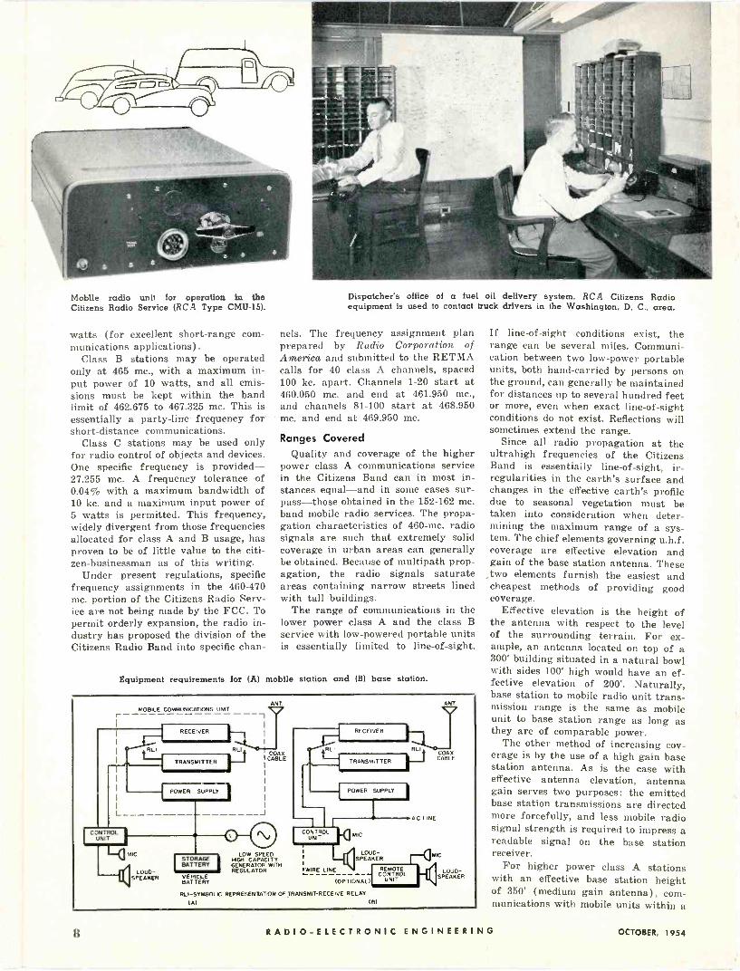
Mobile radio unit for operation in the Citizens Radio Service (RCA Type CMU-15).
watts (for excellent short-range com- munications applications).
Class B stations may be operated only at 465 mc., with a maximum in- put power of 10 watts, and all emis- sions must be kept within the band limit of 462.675 to 467.325 mc. This is essentially a party -line frequency for short -distance communications.
Class C stations may be used only for radio control of objects and devices. One specific frequency is provided - 27.255 mc. A frequency tolerance of 0.04% with a maximum bandwidth of 10 kc. and a maximum input power of 5 watts is permitted. This frequency, widely divergent from those frequencies allocated for class A and B usage, has proven to be of little value to the citi- zen -businessman as of this writing.
Under present regulations, specific frequency assignments in the 460-470 mc. portion of the Citizens Radio Serv- ice are not being made by the FCC. To permit orderly expansion, the radio in- dustry has proposed the division of the Citizens Radio Band into specific chan -
Dispatcher's office of a fuel oil delivery system. RCA Citizens Radio equipment is used to contact truck drivers in the Washington, D. C.. area.
nels. The frequency assignment plan prepared by Radio Corporation of America and submitted to the RETMA calls for 40 class A channels, spaced 100 kc. apart. Channels 1-20 start at 460.050 mc. and end at 461.950 mc., and channels 81-100 start at 468.950 mc. and end at 469.950 mc.
Ranges Covered
Quality and coverage of the higher power class A communications service in the Citizens Band can in most in- stances equal-and in some cases sur- pass-those obtained in the 152-162 mc. band mobile radio services. The propa- gation characteristics of 460 -mc. radio signals are such that extremely solid coverage in urban areas can generally be obtained. Because of multipath prop- agation, the radio signals saturate areas containing narrow streets lined with tall buildings.
The range of communications in the lower power class A and the class B service with low -powered portable units is essentially limited to line -of -sight.
Equipment requirements for (A) mobile station and (B) base station.
ANT MOBILE COMMUNICATIONS UNIT
I RL t COAX I CABLE
RECEIVER
TRANSMITTER
L
CONTROL UNIT
MIC
LOUD- SPEAKER
POWER SUPPLY
I _J
STORAGE BATTERY
VEHICLE BATTERY
LOW SPEED HIGH CAPACITY GENERATOR WITH REGULATOR
RECEIVER
RLI RLI
TRANSMITTER
POWER SUPPLY
I
ANT. v COAX CABLE
L IRE A.C.
CONTROL UNIT IC
LOUD- SPEAKER
IMIC v `WIRE LINE- . REMOTE LOUD -
(OPTIONAL) CONTROL
UNIT SPEAKER
RLI-SYMBOLIC REPRESENTATION OF TRANSMIT -RECEIVE RELAY
IA) (B)
If line -of -sight conditions exist, the range can be several miles. Communi- cation between two low -power portable units, both hand -carried by persons on the ground, can generally be maintained for distances up to several hundred feet or more, even when exact line -of -sight conditions do not exist. Reflections will sometimes extend the range.
Since all radio propagation at the ultrahigh frequencies of the Citizens Band is essentially line -of -sight, ir- regularities in the earth's surface and changes in the effective earth's profile due to seasonal vegetation must be taken into consideration when deter- mining the maximum range of a sys- tem. The chief elements governing u.h.f. coverage are effective elevation and gain of the base station antenna. These
two elements furnish the easiest and cheapest methods of providing good coverage.
Effective elevation is the height of the antenna with respect to the level of the surrounding terrain. For ex- ample, an antenna located on top of a 300' building situated in a natural bowl with sides 100' high would have an ef- fective elevation of 200'. Naturally, base station to mobile radio unit trans- mission range is the same as mobile unit to base station range as long as they are of comparable power.
The other method of increasing cov- erage is by the use of a high gain base station antenna. As is the case with effective antenna elevation, antenna gain serves two purposes: the emitted base station transmissions are directed more forcefully, and less mobile radio signal strength is required to impress a readable signal on the base station receiver.
For higher power class A stations with an effective base station height of 350' (medium gain antenna), com- munications with mobile units within a
8 RADIO -ELECTRONIC ENGINEERING OCTOBER, 1954

RCA Citizens Radio mobile unit installed in cab of soft drink delivery truck. Dispatcher can contact driver instantly.
radius of approximately 19 to 20 miles can generally be expected. With an ef- fective antenna elevation of 50', the range is reduced to approximately seven miles. In urban areas, effective eleva- tion is quite often obtained by using tall buildings for base station antenna locations.
Mobile systems employing higher powered class A base stations can be used for providing coverage of large metropolitan areas. Coverage of a large area may be accomplished by em- ploying a single base station with a relatively high antenna system, or a multiplicity of base stations with an- tenna systems of medium effective height.
The vehicle -to -vehicle communicat- ing range in class A service and class B service, under average conditions, is limited essentially to line -of -sight. How- ever, reflections from buildings and other hard surfaces can play an im- portant part in vehicle -to -vehicle trans- mission, particularly in metropolitan areas where signals actually reflect so as to give "around corner" transmission range. Another example of this phe- nomenon is that car -to-car communi- cation has been maintained up to dis- tances of 0.4 mile between two vehicles when both were inside the Lincoln Tun- nel under the Hudson River. Due to the slope of the tunnel, this distance ex- ceeded the exact line -of -sight separa- tion of the vehicles.
For class B services, no particular systems planning problems are evident. Since communication is to be main- tained on a frequency of 465 mc., which is common to all other class B station operators, and power input is limited, very few will plan to use class B serv- ice for wide coverage of a metropolitan area. A large number of stations can operate on this single frequency within a few miles of each other without seri -
Dispatcher's office employing RCA Citizens Radio for soft rink delivery. Remote control unit is on shelf above dispatdher.
ous mutual interference if antenna heights are kept low.
Licensing
Ordinarily, except for good cause, a station license will not be granted in the Citizens Radio Service if the ap- plicant is also eligible for a license in one of the other established radio services. The license period is for five years. No operating log is required but station identification must be an- nounced at the beginning and the end- ing of each transmission, and at least once each ten minutes during prolonged transmissions.
At the present time, no fees or charges are made for Citizens Radio Service licenses, nor is an operator's license required for voice operations. Citizens' stations using manually op- erated telegraph transmitting by any type of Morse code require operation
Stewart -Warner Portafone two-way unit for class B Citizens Radio Service. Unit is shown here with a.c. power supply in lieu of a battery pack.
1
by an individual holding a radiotele- graph operator's license of either the Radiotelegraph Third Class Oper for Permit or higher. In making app ica- tion for a Citizens Radio statio li- cense, FCC Form 505 should be om- pleted and submitted to the ne est regional FCC office or to the Fe. rat Communications Commission, Wash ng- ton 25, D. C.
Technical information on the eq ip- ment to be used, generally avail : ble from the manufacturer, must be up - plied with the license application u ess the equipment manufacturer has al- ready submitted this information di ect to the FCC, in which case the FCC ype approval number should be entere on the license application form.
Relay stations, under some circ in- stances, may be licensable for exten ing the range of mobile -to-mobile comm ni - cations, point -to-mobile communicat' i ns, etc. However, inasmuch as specific , re- quencies are not assigned to licen-ees, the owner of a Citizens Band relay ta- tion may run into troubles since ny radio station within range on the s me frequency could inadvertently acti ate the relay station.
FCC rules governing the Citi ens Radio Service prohibit the contin ous radiation of energy for radio co rol of objects or devices other than model aircraft while in flight. However no stipulation is made against the cont nu- ous radiation of energy as long as the carrier is being modulated for co u- nications purposes.
Equipment and Maintenance Modern Citizens Band equipme is
a precision -built industrial tool. ase stations in class A Citizens Radio S rv- ice (50 -watt input) could be buil to much less stringent specifications, but at present do not differ from base ta -
(Continued on page 36)
OCTOBER, 1954 RADIO -ELECTRONIC ENGINEERING

A BRIDGE FOR JUNCTION TRANSISTOR Adaptation of a commercial vacuum tube bridge for
measuring junction transistor hybrid parameters.
THE ADAPTABILITY of the Gen- eral Radio Type 561-D vacuum tube bridge for the simple and accurate
measurement of the r parameters of point -contact transistors has been dis- cussed'. Further study reveals that this bridge is just as readily adaptable for the simple and accurate measurement of the h or hybrid parameters of the junction transistor with only a few minor modifications. Moreover, as the h parameters are now favored by many engineers working with the junction transistor, the bridge takes on added importance.
Considering the transistor as an ac- tive four -terminal network, as shown in Fig. 1, these small a.c. signal h param- eters may be defined in the following manner :
1133= input impedance with the output short-circuited (y, = 0)
lin= output admittance with the input open -circuited (i, = 0)
143= voltage feedback ratio with the in- put open -circuited
h.= -a = negative of the short cir- cuit current gain
Over a small region of the static characteristics, the linear relations be- tween the incremental emitter and col- lector voltages and currents can be de- scribed by the linear equations:
v,=hni,-E-h,a, (1)
had. -{- h22v, (2)
and the slopes of the appropriate set of characteristic curves are expressed by:
h 8V.
h,_ = Sv,
Sv, h,2 = Sv,
(3)
(4)
(5)
= Si, h" Si, v, = 0
Thus, the hybrid parameters contain a resistance h,,, a conductance h__, and two pure numerics, h and h21. (The real components of the impedances are obtained since the small reactive com- ponents are balanced out by the bridge.) Equations (3) through (6) may be closely correlated with the dynamic co- efficients of vacuum tubes, R9, µ and G,.. The General Radio bridge measures these tube coefficients by means of null - balance arrangements of the various alternating increments2' 8. Therefore, it becomes a fairly simple task to adopt these bridge null -balance arrangements for accurate and direct measurement of junction transistor parameters.
The vacuum tube coefficients meas- ured by the bridge are defined in Eqts. (7) through (9).
a,=0
Gm -84 Sv v,-0
(7)
(8)
(9)
Upon examining Eqt. (7), the ex- pression for R it becomes apparent that the increments of alternating volt- age and current involved correspond to those for h of the transistor. Thus, v i and y, correspond to v i and v respectively, if the transistor is re- versed when it is inserted into the bridge so that the emitter side is in- serted into the plate terminal of the bridge and the collector is inserted into the grid terminal. The simplified bridge circuit for measuring R, and the asso- ciated circuit for measuring h are shown in Figs. 2 and 3.
General Radio vacuum tube bridge Type 561-D adapted for transistor measurements.
The test setup for measuring h pro- vides zero alternating voltage in the collector circuit, and the bridge R, cir- cuit measures alternating emitter cur- rent flowing as a result of a small volt- age change introduced into the emitter circuit by e,. Test voltage e, is adjusted so that the resultant current flowing through Rs balances the emitter cur- rent. When the two currents are equal, a null will be exhibited by the detector and the bridge decade resistor balance will yield the value of h,,. Since the sharpness of the null may be obscured by reactive current which arises from transistor capacitances, lead capaci- tances, etc., the reactive current gener- ator e3 (capacitance balancing winding in series with a variable capacitance) is made use of, as shown, and may be ad- justed to pass an equal and opposite re- active current.
Increments of h likewise are analo- gous to those of R9, that is, v, and correspond to y, and i respectively, while the condition i. = 0 may be con- sidered the dual' of y, = 0. It is very simple to satisfy the condition i, = 0 with the insertion of a 600 -henry audio
Table 1. Procedure for measuring junction transistor parameters in grounded base connection. Reference 1 gives switch details.
BRIDGE ADJUSTMENTS ADAPTING PANEL ADJUSTMENTS
Parameter Coefficient to be Selector
Measured Switch & Sign
"Multiply by"
Switch
"Divide by"
Switch
Decade Resistor Balance
Capacitor Multiplier
Switch
Transistor Switch
Switch 1
Switch #2
Switch Bridge 3 Measurements
hr, Rp (+) 1 102 adjust for balance
out test reverse tran - sistor h11 R p
h22 Rp (+) 10 1 normal h22 I/Rp
h12 µ (-) 1 102 4444 ifreverse " h12 µ
h21 Gm (-) 1 1 iinormal her G,,,'10
10 RADIO -ELECTRONIC ENGINEERING OCTOBER, 1954

MEASUREMENTS By DAVID DORMAN
Research Laboratories Sylvania Electric Products Inc.
choke in the emitter circuit; this essen- tially opens the circuit to the bridge test signal of 1000 cps. Since h is a conductance, the value of h will be determined by the reciprocal of the re- sultant Rp value measured. The modi- fied bridge circuit for measuring h is shown in Fig. 4.
The next tube coefficient to be con- sidered is µ, given by Eqt. (8). A nearly parallel situation exists in the measure- ment of h,,, which has been defined to be a ratio of the change in emitter volt- age as a result of small changes in col- lector voltage under the condition that there be no alternating current in the emitter (Eqt. (5) ). By reversing the transistor emitter and collector leads so that the bridge measuring circuit is placed in the emitter circuit, the exact requirements for measuring h are met. This test setup for h provides an a.c. open circuit in the emitter when a null balance is obtained. Therefore:
h,, = µ reading (10)
It is very important in measuring h to throw the sign of coefficient switch to negative, as signals transmitted through the vacuum tube undergo a phase re- versal while signals are transmitted through the transistor without phase changes. Thus, reversing the sign of co- efficient switch is necessary to supply accurate in -phase test voltages to the transistor under test. Figure 5 shows the bridge circuit for measuring µ, and Fig. 6 shows the modified 1.4 circuit de- signed to measure h,,.
When measuring the transconduc- tance of a- tube with the bridge, the alternating plate current flowing as a result of a small signal voltage intro- duced into the grid circuit is determined under the condition that there be no al- ternating voltage on the plate. A very similar situation exists in the measure- ment of h,,, which has been defined to be a measure of the alternating collec- tor current flowing as a result of small changes in emitter current under the condition that there be no alternating voltage on the collector. Figure 7 shows the bridge circuit for measuring G,,,, and Fig. 8 shows the modified G,2 cir- cuit designed to measure h,,. The G,,, position measures:
Sve
(Continued on page 39)
Fig. 4. Modified R,, bridge circuit designed to measure the h char- acteristic of junction transistors.
Fig. 6. Modified µ bridge cir- cuit for measuring the h,, charac- teristic of junction transistors.
Fig. 1. Equivalent circuit of transistor shown as an active four -terminal network.
Fig. 2. Simplified bridge circuit for measuring R,, of a vacuum tube
Fig. 3. Modified R bridge circuit designed to measure h,, of junction transistors.
o
Fig. 5. Simplified vacuum tube bridge circuit for measuring am- plification factor (µ) of a tube.
Fig. 7. Simplified vacuum tube bridge circuit for measuring the transconductance (G,,.) of a tube.
Fig. 8. Modified G. bridge cir- cuit for measuring the h_, charac- teristic of junction transistors.
OCTOBER, 1954 RADIO -ELECTRONIC ENGINEERING 11

A VERSATILE PULSE SHAPER By GEORGE E. KAUFER
Columbia University
Thyratron circuit reforms incoming pulses, providing
a train of constant -amplitude constant -width pulses.
IN COMPUTERS and other pulse cir- cuitry, it is often desirable to be able to reform sloppy pulses so that the
resultant waveform will meet certain required specifications. Such reform- ing is particularly important where a train of high -amplitude sharp pulses is to be distributed centrally to remote parts of an installation via low -imped- ance coaxial lines. If the pulses origi- nally available have variable amplitudes and widths, they must be reshaped be- fore distribution. This article will de- scribe the development of a circuit which can accomplish the necessary re- shaping. It should be borne in mind that simplicity, reliability, compactness and economy are of prime importance in pulse shaper design, and that these factors govern the final choice of circuit.
Problem Given-a set of sloppy incoming pulses conforming to the following specifica- tions: 1. Amplitude-between 25 and 100 volts 2. Polarity-positive 3. Rise time-less than 0.5 µsec. (10-
90%) 4. Width-from 1 to 50 µsec. between
points which are 50% of peak ampli- tude on the initial rise
5. Backswing-less than 25% of max- imum amplitude
6. Source impedance-between 500 and 5000 ohms
7. Minimum pulse spacing -2000 µsec. between pulses
Find-a simple one -tube circuit to ac- cept these pulses and provide as an out- put a train of constant -amplitude and constant -width pulses conforming to the following specifications: 1. Amplitude-greater than 75 volts 2. Polarity-negative 3. Rise time-better than 0.1 µsec. 4. Width-greater than 0.2 µsec. be-
tween points which are 50% of peak amplitude on the initial rise
5. Backswing-less than 1 volt 6. Output impedance-low enough to
drive a 100 -ohm line The terminology used in these spe-
cifications is illustrated in Fig. 1. The pulse -reshaping circuit which has been developed will not only conform to the
above specifications but can be easily modified to yield a variety of output pulse amplitudes and widths. Circuit constants are listed and resultant out- put waveshapes sketched.
Circuit Development
A majority of the currently employed pulse -reshaping circuits which are to drive low impedance lines are centered about blocking oscillators. The low out- put -impedance requirement presents a severe limitation on the choice of an adequate circuit. After considerable thought, a blocking oscillator type gen- erator was rejected because of the fol- lowing drawbacks: 1. A blocking oscillator transformer
would have to be designed and com- pactly constructed.
2. To eliminate backswing in the nega- tive pulse output, the line would have to be capacitively coupled, ne- cessitating the use of a physically large capacitor (approximately 0.05- µfd.) .
3. Eight components and a high power dual triode would be necessary, yielding only a scant maximum of approximately 75 -volts output with- out paralleling tubes.
4. Fairly high voltage bias supplies would have to be constructed, re- quiring additional large components as well as special transformers. For added versatility, it is assumed that there are no negative supplies present.
Reliable triggering from the given pulses, and sharp negative output pulses greater than 75 volts in amplitude into a 100 -ohm line were achieved in an experi- mental design using a 2D21 miniature thyratron. The cathode was grounded di- rectly, resulting in a single high -ampli- tude negative -pulse output. If necessary, either output polarity could be obtained by replacing the load resistor with a pulse transformer and taking the out- put from one or the other terminal; however, such operation would intro- duce many of the disadvantages inher- ent in blocking oscillator units.
A variety of two -terminal pulse net- works was tried, ranging from a single
Assembled view of pulse shaper.
0.015-µfd. capacitor to a 10-µhy. induc- tor shunted by a 1N48 diode, all in series with a 0.002-µfd. capacitor. A tabula- tion of networks with relative resultant waveshapes has been formulated in Fig. 4 for purposes of comparison. It was found that a small series inductance considerably lengthened the discharge time of the capacitor, permitting one to obtain a wide range of output pulse shapes and widths. Although the opposi- tion to changes in current afforded by the inductance appreciably lengthens the output pulse, this phenomenon is accompanied by a corresponding de- crease in pulse amplitude-due to the fact that the total area under the curve represents energy and the source energy stored in the plate capacitor is fixed.
The next consideration was that of triggering with short pulses. The mech- anism of initiating conduction consists of injecting on the grid a positive pulse large enough in amplitude to cause the gas between grid and cathode to ionize. If the pulse amplitude at the grid is maintained, the arc is transferred to the plate and the tube breaks down. On the other hand, if the pulse amplitude decreases appreciably, the grid -cathode arc will extinguish itself before it has transferred to the plate, and the tube will remain in the nonconducting state. It might be anticipated that as the trig- ger pulse width is decreased the mini- mum trigger amplitude required would increase. Unfortunately, when the grid - cathode circuit ionizes, the network consisting of the series grid -limiting re- sistor and the grid conducting resistance acts to attenuate the input trigger. This is especially serious for triggers of short duration, as the area under the pulse directly at the grid is low and hence the initial amplitude must be cor- respondingly high.
Since the quiescent bias voltage on the thyratron is somewhat greater than that required to prevent the tube's firing, and since for proper operation the firing of a thyratron must be posi -
12 RADIO -ELECTRONIC ENGINEERING OCTOBER, 1954

100 -- PULSE Y0
AMPLI -I PULSE TUDE
50 SPACING
POLARITY _
RISE --BACKSWING TIME TIME AXIS
Fig. I. Pulse waveform characteristics.
tive, it is usual to drive the grid well beyond the critical point when firing. Such a practice creates the need for a finite amount of grid power, and any circuitry feeding the grid must be capa- ble of delivering this power. The grid current loads the driver circuit which tends to reduce the actual voltage appearing at the grid. In very high impedance circuits, the trend of this effect is to make the operation of the tube independent of the intended actuat- ing voltage. In addition, the effect may vary; e.g., as the tube warms up, its characteristics change. Thus, the grid resistor is reduced to a minimum value so that reliable triggering may be ob- tained from fractional microsecond pulses. In the final circuit, 10,000 ohms was found to be a good compromise value.
The graph of Fig. 3 illustrates the aforementioned statements. A fixed grid bias of -4 volts was used to obtain data for the curve, a value which was found to produce the best results. A larger negative bias would require an even greater trigger amplitude as well as introduce power supply design prob- lems, whereas a more positive bias would result in the thyratron oscillator becoming astable.
In an effort to speed up the ionization time, pulsing and biasing of alternate grids was tried (see Fig. 7) as well as tying both grids together and triggering them simultaneously. The latter yielded the worst condition, requiring 48 volts with 1/2 -µsec. triggers instead of 25 volts if only one grid were pulsed. Little im- provement was noted by employing the complex scheme of Fig. 7 in place of simple triggering, so the idea was aban- doned.
Final Unit The final unit is shown schematically
in Fig. 6. Adequate peak current limit- ing is provided by the 100 -ohm load. The compromise in plate pulse -forming net- work eventually resorted to consists of the series combination of a 5-µhy. coil and a 0.001-µfd. capacitor. At a pulse repetition frequency of 400 cycles, the peak output is 140 volts negative (see graph of Fig. 2) into a 100 -ohm line with a pulse width (50% down) of 0.28 µsec. The rise time (0.1 to 0.9) is 0.08 µsec. and there are no oscillations. No output coupling capacitor is required.
Fitting neatly into a one -tube vector can, the thyratron sharpener meets all
(Continued on page 33)
O
12v
100V
O
12VI
30V
71
w.O 25.ec T.0 0595e<
0.9 use<
tr. 355ec
W.0.5 pm T0.2 use <
toll. 2 55e<
0015u10
O - - 0 002510
I thy
CCCGIIII
OOISuIa
1 thy
0002u10
IO shy bl
0-f 00 j_ 00020ro
O
IBV
o
w'3y5t<
w0.45501
0 uhy
0-1.00i -r001SWa
10" AI
78V T .0.1 owc
1011 2.515ec IN48 0002510
w.WIDTH AT 50% AMPLITUDE TRISE TIME 110-90%)
Fig. 4. Output waveshapes and plate circuit elements for basic unit.
IN34
CATH
RFC 10 thy
180X1.
00 50510 .5510. I .S00. o
25v. + OIL OIL
C.T,
I
. 6.3V TO ALL HEATERS
4 7 1
1
Ico tono mono TRIGGER SPACINGI)JSEC)
Fig. 2. Output amplitude vs. input trigger spacing for a fixed load and a 680 -µsec. plate time constant.
28
2 4 6 8 TRIGGER PULSE W DTH I3JSEC)
10
Fig. 3. Trigger amplitude vs. pulse width for fixed bias of -4 volts.
Fig. 6. Schematic diagram and parts values for thyratron pulse shaper.
9 PIN OCTAL SOCKET
TERMINATED 10011. LINE
Fig. 5. Schematic diagram and parts values for a compact bias supply.
Fig. 7. Triggering circuit in which both grids are pulsed simultaneously.
OCTOBER, 1954 R ADIO -ELECTRONIC ENGINEERING 13

NARROW BAND
FOR MORE
CLEAR CHANNELS
By J. A. McCORMICK
Commercial Engineer, General Electric Company
Factors involved in reducing channel width in the
25-50 and 152 -174 mc. bands to improve operation.
CHANNEL -SPLITTING represents a practical means of accommodating the maximum number of users in a given spectrum space. There are now a great many systems
operating on a 20-kc. basis in the 25-50 mc. band and expe- rience has shown that maintenance of narrow -band equip- ment is no more difficult, time-consuming or expensive than the maintenance of comparable wide -band equipment.
In the spring of 1949, the General Electric Company intro- duced a line of high -selectivity 20-kc. equipment for opera- tion in the 25-50 mc. band, and since that time has manufac- tured both 20-kc. and 40-kc. equipment concurrently on the same production lines. The two types of equipment are iden- tical in appearance, and the 40-kc. or wide -band equipment was designed for ease of conversion in the field to split -chan- nel operation whenever a user desires-or may be required by FCC action-to make the change. Figures 1, 2, 3 and 4 illustrate the simple steps required to make this conversion. (The same technique applies to G -E 152-174 mc. equipment.)
Users in the petroleum radio service, because of their concentration in a limited geographic area, were among the first to feel the pinch of a limited number of channels, with the result that they have turned to narrow -band opera- tion in fairly large numbers as a means of minimizing co - channel and adjacent channel interference. Several users have installed actual split channel systems on a develop- mental grant from the FCC-a sound approach on the part of any new user who is faced with the necessity of other- wise sharing the same channel with an existing system.
The case of three companies operating in Louisiana pro- vides an example of this approach. The Midstates Oil Cor- poration and the Transcontinental Gas Pipe Line Company originally operated narrow -band systems but shared the same frequency, 48.74 mc., with the attendant interference to each other's operation. At 48.70 mc., only 40-kc. below, is the wide -band system of Interstate Petroleum Commu- nications. In May, 1953, Midstates sought and obtained FCC authority to shift 20 kc. in frequency to 48.72 mc., so that the three systems are now spaced at 20-kc. intervals. These systems have since operated on that basis and no interfer- ence has been reported.
Performance Comparison How does the performance of narrow -band equipment
compare with that of wide -band equipment? There are three
Fig. 1. In converting from wide -band to narrow -band operation, the first step is to remove the three low i.f. transformers from the receiver chassis.
experimental land stations at Syracuse geographically spaced on the points of a triangle and controlled from a central point so that controlled tests of all types can be made under practical conditions. Using these facilities, comparative 20-kc. vs. 40-kc. tests were made for represent- atives of the FCC in April, 1949, and have been made for many user groups since that time.
The station operator has a means of switching the peak modulation instantly from ± 15 kc. to ± 6 kc., or vice- versa, on the desired or adjacent channel transmitters. He also has a means of shifting the desired carrier frequency by any desired increment. The station wagon in which the observers ride is equipped with a narrow -band receiver and a wide -band receiver, which can be alternately switched to a common antenna and loudspeaker. A transmitter is pro- vided for communication with the station operator.
Before leaving the vicinity of the desired station trans- mitter location, the squelch and volume controls of the two receivers are adjusted to the same level. They then remain untouched for the duration of the tests. Comparative tests should not be made using just a wide -band receiver, and resetting the volume control as the modulation is changed from wide -band to narrow -band, because the narrow -band reception will be penalized in signal-to-noise ratio by virtue of the fact that the wide -band receiver will admit a wider spectrum of noise due to its wider passband.
In the good signal areas, the signal-to-noise ratio of the wide -band equipment is about 3 db better than that of the narrow -band equipment. This is about the smallest differ- ence that can be detected by the human ear and is evident only in a side -by -side comparison. In the "fringe" areas, surprisingly enough, the signal-to-noise ratio of the narrow - band equipment is actually superior to that of the wide - band equipment; therefore, it can be concluded that the ultimate range of a narrow -band system is at least equal to a wide -band system.
It has been observed that ignition noise and off -frequency operation of 1, 2 or 3 kc. have a somewhat greater degrada- tion on narrow -band operation than on wide -band operation, but these factors are controllable and need not be decisive. The superiority of narrow -band operation shows up quite dramatically whenever an interfering signal is introduced. Whenever interference is-or is likely to be-a factor, the narrow -band system is the right answer.
14 RADIO -ELECTRONIC ENGINEERING OCTOBER, 1954
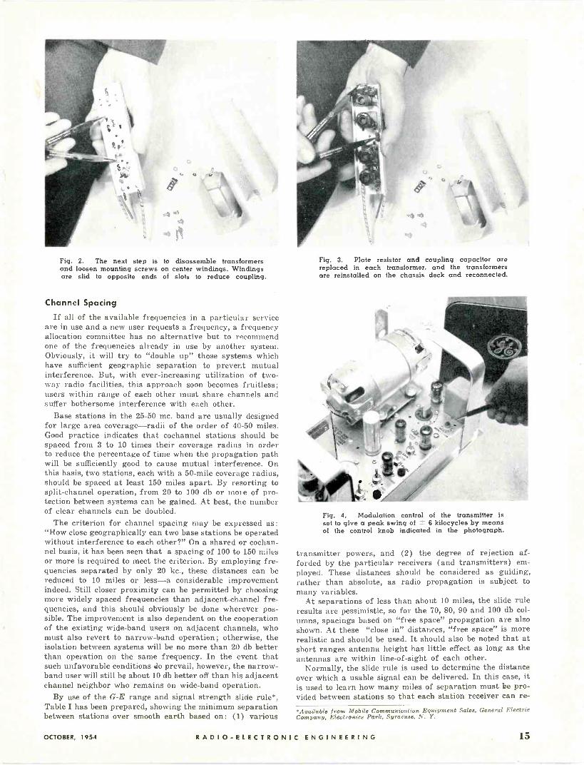
Fig. 2. The next step is to disassemble transformers and loosen mounting screws on center windings. Windings are slid to opposite ends of slots to reduce coupling.
Channel Spacing
If all of the available frequencies in a particular service are in use and a new user requests a frequency, a frequency allocation committee has no alternative but to recommend one of the frequencies already in use by another system. Obviously, it will try to "double up" those systems which have sufficient geographic separation to prevent mutual interference. But, with ever-increasing utilization of two- way radio facilities, this approach soon becomes fruitless; users within range of each other must share channels and suffer bothersome interference with each other.
Base stations in the 25-50 mc. band are usually designed for large area coverage-radii of the order of 40-50 miles. Good practice indicates that cochannel stations should be spaced from 3 to 10 times their coverage radius in order to reduce the percentage of time when the propagation path will be sufficiently good to cause mutual interference. On this basis, two stations, each with a 50 -mile coverage radius, should be spaced at least 150 miles apart. By resorting to split -channel operation, from 20 to 100 db or more of pro- tection between systems can be gained. At best, the number of clear channels can be doubled.
The criterion for channel spacing may be expressed as :
"How close geographically can two base stations be operated without interference to each other?" On a shared or cochan- nel basis, it has been seen that a spacing of 100 to 150 miles or more is required to meet the criterion. By employing fre- quencies separated by only 20 kc., these distances can be reduced to 10 miles or less-a considerable improvement indeed. Still closer proximity can be permitted by choosing more widely spaced frequencies than adjacent -channel fre- quencies, and this should obviously be done wherever pos- sible. The improvement is also dependent on the cooperation of the existing wide -band users on adjacent channels, who must also revert to narrow -band operation; otherwise, the isolation between systems will be no more than 20 db better than operation on the same frequency. In the event that such unfavorable conditions do prevail, however, the narrow - band user will still be about 10 db better off than his adjacent channel neighbor who remains on wide -band operation.
By use of the G -E range and signal strength slide rule*, Table I has been prepared, showing the minimum separation between stations over smooth earth based on: (1) various
Fig. 3. Plate resistor and coupling capacitor are replaced in each transformer, and the transformers are reinstalled on the chassis deck and reconnected.
Fig. 4. Modulation control of the transmitter is set to give a peak swing of ± 6 kilocycles by means of the control knob indicated in the photograph.
transmitter powers, and (2) the degree of rejection af- forded by the particular receivers (and transmitters) em- ployed. These distances should be considered as guiding, rather than absolute, as radio propagation is subject to many variables.
At separations of less than about 10 miles, the slide rule results are pessimistic, so for the 70, 80, 90 and 100 db col- umns, spacings based on "free space" propagation are also shown. At these "close in" distances, "free space" is more realistic and should be used. It should also be noted that at short ranges antenna height has little effect as long as the antennas are within line -of -sight of each other.
Normally, the slide rule is used to determine the distance over which a usable signal can be delivered. In this case, it is used to learn how many miles of separation must be pro- vided between stations so that each station receiver can re -
',Available from Mobile Communication Equipment Sales, General Electric Company, Electronics Park, Syracuse, N. Y.
OCTOBER, 1954 RADIO -ELECTRONIC ENGINEERING 15
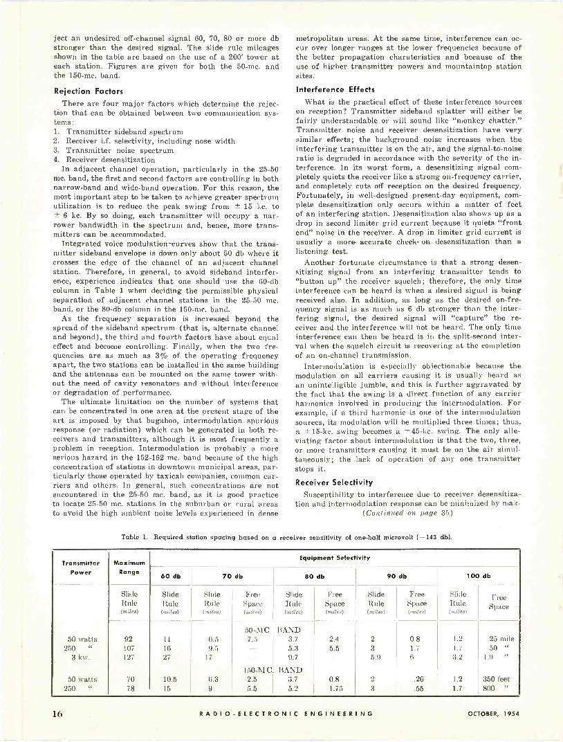
ject an undesired off -channel signal 60, 70, 80 or more db stronger than the desired signal. The slide rule mileages shown in the table are based on the use of a 200' tower at each station. Figures are given for both the 50 -mc. and the 150 -mc. band.
Rejection Factors There are four major factors which determine the rejec-
tion that can be obtained between two communication sys- tems: 1. Transmitter sideband spectrum 2. Receiver i.f. selectivity, including nose width 3. Transmitter noise spectrum 4. Receiver desensitization
In adjacent channel operation, particularly in the 25-50 mc. band, the first and second factors are controlling in both narrow -band and wide -band operation. For this reason, the most important step to be taken to achieve greater spectrum utilization is to reduce the peak swing from ± 15 kc. to
6 kc. By so doing, each transmitter will occupy a nar- rower bandwidth in the spectrum and, hence, more trans- mitters can be accommodated.
Integrated voice modulation curves show that the trans- mitter sideband envelope is down only about 50 db where it crosses the edge of the channel of an adjacent channel station. Therefore, in general, to avoid sideband interfer- ence, experience indicates that one should use the 60 -db column in Table 1 when deciding the permissible physical separation of adjacent channel stations in the 25-50 mc. band, or the 80 -db column in the 150 -mc. band.
As the frequency separation is increased beyond the spread of the sideband spectrum (that is, alternate channel and beyond), the third and fourth factors have about equal effect and become controlling. Finally, when the two fre- quencies are as much as 3% of the operating frequency apart, the two stations can be installed in the same building and the antennas can be mounted on the same tower with- out the need of cavity resonators and without interference or degradation of performance.
The ultimate limitation on the number of systems that can be concentrated in one area at the present stage of the art is imposed by that bugaboo, intermodulation spurious response (or radiation) which can be generated in both re- ceivers and transmitters, although it is most frequently a problem in reception. Intermodulation is probably a more serious hazard in the 152-162 mc. band because of the high concentration of stations in downtown municipal areas, par- ticularly those operated by taxicab companies, common car- riers and others. In general, such concentrations are not encountered in the 25-50 mc. band, as it is good practice to locate 25-50 mc. stations in the suburban or rural areas to avoid the high ambient noise levels experienced in dense
metropolitan areas. At the same time, interference can oc- cur over longer ranges at the lower frequencies because of the better propagation charateristics and because of the use of higher transmitter powers and mountaintop station sites.
Interference Effects
What is the practical effect of these interference sources on reception? Transmitter sideband splatter will either be fairly understandable or will sound like "monkey chatter." Transmitter noise and receiver desensitization have very similar effects; the background noise increases when the interfering transmitter is on the air, and the signal-to-noise ratio is degraded in accordance with the severity of the in- terference. In its worst form, a desensitizing signal com- pletely quiets the receiver like a strong on -frequency carrier, and completely cuts off reception on the desired frequency. Fortunately, in well -designed present-day equipment, com- plete desensitization only occurs within a matter of feet of an interfering station. Desensitization also shows up as a drop in second limiter grid current because it quiets "front end" noise in the receiver. A drop in limiter grid current is usually a more- accurate check on. desensitization than a listening test.
Another fortunate circumstance is that a strong desen- sitizing signal from an interfering transmitter tends to "button up" the receiver squelch; therefore, the only time interference can be heard is when a desired signal is being received also. In addition, as long as the desired on -fre- quency signal is as much as 6 db stronger than the inter- fering signal, the desired signal will "capture" the re- ceiver and the interference will not be heard. The only time interference can then be heard is in the split-second inter- val when the squelch circuit is recovering at the completion of an on -channel transmission.
Intermodulation is especially objectionable because the modulation on all carriers causing it is usually heard as an unintelligible jumble, and this is further aggravated by the fact that the swing is a direct function of any carrier harmonics involved in producing the intermodulation. For example, if a third harmonic is one of the intermodulation sources, its modulation will be multiplied three times; thus, a ±15-kc. swing becomes a ±45-kc. swing. The only alle- viating factor about intermodulation is that the two, three, or more transmitters causing it must be on the air simul- taneously; the lack of operation of any one transmitter stops it.
Receiver Selectivity Susceptibility to interference due to receiver desensitiza-
tion and intermodulation response can be minimized by mak- (Continued on page 35)
Table 1. Required station spacing based on a receiver sensitivity of one-half microvolt (-143 db).
Transmitter Power
Maximum Range
Equipment Selectivity
60 db 70 db 80 db 90 db 100 db
Slide Rule (miles)
Slide Rule (miles)
Slide Rule (miles)
Frei. Spauo (miles)
Slide Rule (miles)
Free Space
Slide Rule (miles)
Free Space (miles)
Slide Rule (miles)
Free Space
50 -MC. BAND 50 wa, 92 11 6.5 7.5 3.7 2.4 2 0.8 1.2 .25 mile
250 107 16 9.5 5.3 5.5 3 1.7 1.7 .50 "
3 . 127 27 17 9.7 5.9 6 3.2 1.9
150 -MC BAND a0 N"atta 70 10.5 6.3 2.5 3.7 0.8 2 .26 1.2 350 feu!
250 " 78 15 9 5.5 5.2 1.75 3 .55 1.7 800 "
I t) RADIO -ELECTRONIC ENGINEERING OCTOBER, 19.53

COMPONENTS FOR PRINTED CIRCUITS By JOHN F. X. MANNIX and SHERMAN
Squier Signal Laboratory
Acceptance of the Auto-Sembly
technique of circuit assembly
has resulted in new component
designs to fit this technique.
THE Auto-Sembly system of circuit fabrication has received widespread acceptance throughout industry since
its inception by the Signal Corps prior to 1949. This reception by industry confirms the soundness of the basic concept, namely, reliable components united to prefabricated circuitry by a mass assembly operation.
Process steps for the system include :
(1) preparing an insulating card with prefabricated conductors having per- forated terminations to receive the component leads, (2) component mount- ing by insertion of the component leads through the perforations, and (3) solder -fluxing followed by solder -dip- ping and the removal of excess leads when necessary. The application of a protective coating to the circuitry, en- capsulation, or other types of packag- ing may follow, depending upon service requirements. A five -tube clock radio fabricated by this method is illustrated in Fig. 1.
Many types of conventional compon- ents are directly applicable to the sys- tem as evidenced by current commercial and military applications utilizing these components. Other conventional com- ponents require only slight modification to achieve complete compatibility. Man- ufacturers are now providing resistors, capacitors, coils, i.f. transformers, etc., with modified leads that greatly im- prove their applicability to this mass assembly technique. Component assem- blies such as "printed" RC networks manufactured by several commercial suppliers are also directly applicable to prefabricated circuitry.
Reactive components formed of pre- fabricated circuitry are practical where the operating frequency and the re- quired values do not result in a com- ponent area incompatible with the degree of over-all miniaturization de- sired. Such a component is illustrated in Fig. 2, which shows a 40 -mc. i.f. transformer for TV applications. The electrical characteristics of the base material are important in the design
G. BASSLER
Fig. 1. A clock radio made by Hallicrafters utilizing the Auto-Sembly technique. Lower left: printed circuit phenolic chassis; lower right: chassis with sockets added.
of these components. Inductors formed of monoplanar prefabricated circuitry usually are designed in a spiral, square or rectangular configuration. Similarly, capacitors of low values may be formed by interleaved conductor lines or by conductive areas on opposing sides of the base material which serves as the dielectric.
It should be pointed out that the majority of the components covered in the following discussion are items de- veloped primarily for commercial appli- cations. In light of this fact, some of the components may not meet all of the requirements for reliable operation un- der the severe operating conditions encountered by military field equipment.
Assembly of equipment using pre- fabricated circuitry has been greatly facilitated by the recent development of components such as resistors having mounting leads of proper length and special configurations. A swaged flat section on the leads or a slight bend serves to retain the component on the base after insertion of its leads in the terminal perforations (see Fig. 3). The snap -in action and the self -retention feature achieved by this design are
definite advantages; the self -retention feature insures proper positioning of the component during the dip -soldering operation and eliminates the need for any component holding device. Other advantages include saving in metal (no excess lead length) and elimination of the lead trimming operation. A sim- ilar snap -in design has been used for the leads and terminal tabs of i.f. transformers, r.f. coils, and slide switches, as illustrated in Fig. 5.
Components requiring additional mechanical support may have acces- sory parts designed to incorporate the same snap -in features. Such a case is shown in Fig. 5 (right), where the ver- tical mounting of two adjacent resistors is effected by means of a spring action snap -in yoke. This assembly is being used in a home radio receiver manufac- tured by the Philco Corporation.
Shown in Fig. 6 is a`:rotary switch employing printed circuitry to form the contacts on the stator; there are sev- eral switches of this type cómmercially available. A switch may also be directly integrated with the printed circuit chassis. Such a switch has the stator segments formed simultaneously with
OCTOBER, 1954 RADIO -ELECTRONIC ENGINEERING 17

Fig. 2. RCA 40 -mc. TV i.f. transform- er formed by etched foil technique.
sZ)
Fig. 3. IRC resistors with leads de- signed for printed circuit applica- tions shown mounted and unmounted.
Fig. 4. Experimental five -tube a.c: d.c. amplifier made with printed circuit tech- nique, miniature tube socket adapters, and Auto-Sembly system of fabrication.
Fig. 5. Commercial items suitable for Auto-Sembly system of circuit fabrication: (left to right) i.f. transformer, oscillator coil, slide switch, and resistors.
Fig. 6. Two views of a rotary switch with a printed circuit stator. This switch is manufactured for commercial applications by the Doyen Company.
the circuit conductors; the rotor, shaft detent mechanism and printed circuit stator are assembled on the chassis or card. The multimeter switching circuit illustrated in Fig. 7 provides an ex- ample of this principle; it was devel- oped by Coles Signal Laboratory and is presently being used in a military test instrument.
Components for the Auto-Sembly sys- tem should have stiff, fixed, protruding terminations to permit manual or auto- matic insertion of the component leads into the appropriate perforations in a printed circuit board. It is an accepted concept that socket contacts require "float" (movement within the cavity walls of the socket) to accept the tolerances found on the pin circles and pin diameters of tubes and other plug-in type components. The soldering tabs found on conventional sockets therefore have a certain freedom of motion, and this freedom makes it difficult to insert the tabs into the mounting holes in the circuit board. Excessive tolerance in circuit -board hole diameters is required to accommodate the soldering tabs unless a careful man- ual adjustment is performed on each tab. Dip -soldering of the tabs in the oversize perforations is also difficult unless the tabs are bent over onto the terminal areas. As the transmission to the printed circuitry of tube insertion forces is undesirable, such forces should be eliminated as much as possible in the design of sockets for printed circuit applications.
A five -tube experimental amplifier with adapter -type sockets is shown in Fig. 4. The adapter socket is one of the first approaches to the socketing of electron tubes and other plug-in type components in the Auto-Sembly sys- tem. In this method, adapter pins are staked into the phenolic chassis and solder -dipped to form a good electrical connection to the circuit conductors, and the phenolic adapter body is then pressure -fitted over these pins. The in- sulator body contains double -action beryllium copper springs; one side of a spring makes a firm contact with the adapter pins while the other side re- ceives the pins of the units being in- serted into the adapter. This type of adapter has been used in some commer- cial and military equipment to retain the
Fig. 7. Experimental etched foil multimeter circuit developed by the Coles Signal Laboratory.
i
RADIO -ELECTRONIC ENGINEERING OCTOBER, 1954

7- and 9 -pin miniature and octal electron tubes as well as 14- and 20 -pin relays. Electrical performance of an adapter - type socket (properties of the contacts, the insulation resistance and the break- down voltage between contacts) com- pares favorably with regular tube socket performance. As the adapter contacts have little "float," care must be exercised when inserting miniature tubes into the socket to assure that the delicate glass headers are not damaged. Since the adapter is held firmly to the chassis by the action of its springs against the adapter pins, no additional means of mounting is required. Extra assembly time is required when using this type of adapter since each contact pin must be riveted to the chassis.
Three other types of sockets that have been used with printed circuitry are shown in Fig. 8, all of which have rigid contacts with no "float." At the right is a type of "snap -in" socket which has its contacts placed inside a molded phenolic body and held in place by a disc riveted to the top of the socket. Contact tabs protrude from the top and are bent down along the sides of the body. The socket is pressed into the chassis hole from the top; phenolic ledges between the contacts keep the top of the socket above the chassis, and the spring action of the tabs holds the socket in place. Past experience has shown that sockets having a laminated construction are prone to trap moisture when subjected to the severe humidity conditions encountered in military service. Commercial applications do not impose this stringent requirement upon tube sockets.
Next to this socket in Fig. 8 is another "snap -in" type (a second manufacturer's version is shown in Fig. 9). This type of socket is an adaptation of the stand- ard miniature tube socket employing the conventional socket insulator body with a standard -type contact lengthened and shaped to fit back over the sides. It is pressed into place with the contact tabs serving as snap springs to retain the socket in a card; no other means of mounting is necessary. Satisfactory results have been obtained with this type of socket in a number of com- mercial applications. It is available with both general-purpose and low -loss phenolic insulator bodies in both the
(Continued on page 34)
Fig. 8. Sockets for printed circuit applications made by Cinch Mfg. Corp.
11111111111111111111111 Fig. 9. Printed circuit miniature tube socket manufactured by Methode Mfg. Corp.
Fig. 10. An experimental superregenerative receiver with printed circuit submin- iature sockets. The Auto-Sembly technique was used for circuit fabrication.
11111111111111111011111.1
Fig. li. Repectacle for printed circuit card, made by Winchester Electronics, Inc.
Fig. 12. Over-all view shows five types of card receptacles designed for printed circuit applications. Center: printed circuit card and receptacle in mated position.
» .4111.4,111.141.11, 40.1111.4.1.er
OCTOBER, 1954 RADIO -ELECTRONIC ENGINEERING 1t

R.F. MULTIPLEXING WITH
CAVITY FILTERS
Fig. I. A set of transmitting and receiving cavity filters being tuned.
With radio frequency combining techniques, a single
antenna can be used with more than one radio terminal.
RADIO circuits can be combined for transmission over a common an- tenna in much the same way that
telephone circuits are combined for transmission over a common line. How- ever, when more than two circuits are to be operated over the same route, practical considerations usually require that the receivers be operated from one antenna and the transmitters from an- other. With presently available Lenkurt radio equipment for the 900 -mc. band, up to three transmitting and three re- ceiving frequencies are used over a
Fig. 2. Block diagram of two transmitters and two receivers diplexed over a common antenna by the use of directional filters.
TUNED CA, TEES
© ©
single multisection route at the same time.
Operation of more than one radio transmitter or receiver over one anten- na, called multiplexing, is made possible by the use of tuned cavity directional filters. These filters perform the same circuit function at microwave frequen- cies that conventional coil -capacitor di- rectional filters perform at carrier and voice frequencies. They prevent mutual loading between individual transmitters or receivers, reduce the output of modu- lation products from transmitters, and prevent overloading of the receivers by unwanted out -of -band signals.
Three combinations of transmitters and receivers are commonly used in Lenkurt microwave systems: a single transmitter and receiver on one an- tenna; two transmitters and receivers on one antenna; and three transmitters on one antenna with three receivers on a separate antenna. In every case, sep- arate frequencies are required for each transmitter and receiver. With the fil- ters now in use, the minimum frequency separation necessary between any
'This article is based on material which appeared in the July, 1954, Lenkurt Demodulator, published by Lenkurt Electric Co., Inc., San Carlos, Calif.
60
50
30
rc 20
CI
INSERT I5 1/2
LEERS
ON db
1
MAY
LOSS
: CF
BE TUNED
OF
RECEIVING
1---
TRANSMI
1
COR MID
TTrN FILTER.
BAND
FILTER
2db
FA , , Ira '
rRFCLTERGI .. .I liII P ill ' r TRANSMITTING
FI LEER ,l 1 i I IL. 15 -5 0 5 -.0
FREQUENCY N MEGACYCLES RELATIVI TO MI WAND FREQUENCY
Fig. 3. Curves showing the frequency response of transmitting and receiving filters. Two series cavities are used for transmitting and four for receiving.
I5
transmitter and receiver is normally about 12 mc.; between any two trans- mitters or any two receivers, it is about 6.3 mc. This separation is dictated pri- marily by the directional filter charac- teristics shown in Fig. 3.
The transmitting filters consist of two individual cavities connected in series, while the receiving filters con- sist of four cavities connected in se- ries. Only two cavities are required for the transmitter filters because their principal functions are to reduce the output of modulation products and pre- vent mutual loading. The receiving fil- ters must also screen out out -of -band signals that may be picked up by the antenna. Figure 2 shows how tuned cavity directional filters are used to connect two transmitters and two re- ceivers to a common antenna.
Maximum use of the 900 -mc. band for the operation of microwave com- munications over a common path with several repeaters is achieved with three radio circuits in parallel. For a single hop system, additional parallel radio circuits can be operated between two points. By the use of two antennas per terminal (one for transmitting and one for receiving) and presently available Lenkurt single-sideband equipment, up to 168 channels can be transmitted and received over a multisection route at the same time.
20 RADIO -ELECTRONIC ENGINEERING OCTOBER, 1954.

are you fi
Are you looking for complete electrical circuit dependability in a very, very small space?
If so, you should use Cannon carefully engineered
miniature and sub -miniature multi -contact connec-
tors. In 1/2 or 1/2 the usual space, they give you up
to 50 contacts, the same number as a standard con-
nector, and still retain all the factors of utility, reli-
ability, and mechanical strength found in Cannon's
standard size connectors. They are very rugged, easy
mating, unusually versatile, neat and compact.
Miniatures-Maximum Dimensions Only 1" x 2"!
htirkg space?
first in connectors
High -dielectric insulation. Rack, panel, chassis types
.. recep;acles and pLigs, standarc, pressurized,
or hermetically sealed box, wal or cord mount-
ings ... fr aJdio. co.itrol, and inst ument use. D
and U sub -miniatures have steel shells. IPA and K
miniatures have die-cast shells. Five -ampere gold plated contacts are found in all miriatures and sub -
miniatures, excepting U receptacles which have
steel contacts. Larger contacts having higher cur - .rent ratings, and co -ax contacts. are in process of
deveiopmelt.
Sub-Miniatures-Only 2-5/6" x 39,.64"!
Write for Cannon Miniature and Sub -Miniature Bulletins
Please refer to Dept. 401
CANNON ELECTRIC COMPANY, 3209 Humboldt Street, Los Angeles 31, California.
Factories in Los Angeles, East Haven; Toronto, Canada; London, England.
Representatives and distributors in all principal cities at your service.

COMMUNICATION
RADIO WEATHER FORECASTS
Unusually good radio conditions for international communications which have recently prevailed are expected to continue for the balance of the year, with only a few moderate dis- turbances of short duration, according to John H. Nelson, radio -wave analyst of RCA Communications, Inc., 60 Broad St., New York 4, N. Y. Mr. Nelson, who bases his forecasts of magnetic storms on the position of the planets in rela- tionship with each other and with the sun, had a record of 92% accuracy during the first six months of 1954.
Circle No. 51 on Reader Service Card
SQUELCH UNIT
A codan squelch unit that activates a normally silent Super Pro -600 Ham- marlund receiver at a predetermined signal strength is now available from The Hammarlund Manufacturing Com- pany, 460 West 34th St., New York 1, N. Y. Completely self-contained, it is packaged as an adapter with plug to match one of the existing tube sockets, and obtains its power from the receiver.
The unit's threshold of operation is adjustable to any predetermined level
within the range of r.f. signal inputs of .5 to 100 microvolts. A change in signal carrier level of 2 db or less will complete the switching action of the squelch regardless of threshold setting.
Circle No. 52 on Reader Service Card
RADIO ON THE ATLANTIC
Extensive radio equipment was in- stalled aboard the converted lifeboat "ARIES" before it set sail on its "dou- ble crossing" of the Atlantic Ocean from
Kingston -on -Thames, England, to King- ston -on -Hudson, U.S.A., and back. The equipment was furnished by Rees Mace
Marine Ltd., division of Pye, Limited, Cambridge, England, and consisted of a newly designed Admiralty -type com- munications outfit known as transmit- ter Type 619 and receiver CAT. It made possible continuous communica- tion with Royal Naval wireless sta- tions throughout the world and with many Royal Navy ships on the high seas.
Circle No. 53 on Reader Service Card
MOBILE SYSTEM FOR 144-174 MC.
The third in a series of three mobile transmitter -receiver systems-Type MCA-301-A-has now been announced by Allen B. Du Mont Laboratories, Inc. Covering the 144-174 mc. band, this unit is a complete mobile system which meets all requirements of high stability and ease of maintenance.
Specifically designed to withstand the hard usage of mobile service, Type MCA -301-A is suitable for taxi cabs, forestry service, police, fire department and industrial use. Additional details may be obtained from the Mobile Com- munications Department, Allen B. Du Mont Laboratories, Inc., 1500 Main Ave., Clifton, N. J.
Circle No. 54 on Reader Service Card
MODULATION METER
Because of the rapid development of two-way radio equipment using the 450-470 mc. band, the new Model 205A FM modulation meter is expected to answer a definite need in two-way radio maintenance. With a range of 25 to 500 mc., it has five times more sen-
sitivity than the Model 205, which it replaces, and much better limiting ac- tion extending over a 500 to 1 range of input level.
Announced bÿ Lampkin Laboratories, Inc., Bradenton 15, Florida, the Model 205A measures FM deviation from -± 0 to 25 kc., with an accuracy within 10% of full scale on a 3" meter cal- ibrated in kc. It can also be used as a relative field -strength meter when mak- ing transmitter adjustments.
Circle No. 55 on Reader Service Card
COMMUNICATIONS TUBE
Intended for use in communications equipment and telephone repeater sys- tems, the 9 -pin miniature pentode tube announced by American Radio Com- pany features extremely long operating life. The long life and excellent reli- ability are achieved by means of a patented "Polioptic" manufacturing process which prevents contamination of the tube elements during processing.
Designated as the 404A, this new electron tube employs an oxide -coated cathode, with a heater rating of 6.3 volts, 0.30 amperes. Maximum anode voltage is 180 volts, and anode dis-
sipation 3 watts. Inquiries should be addressed to American Radio Company, Dept. 127, 445 Park Ave., New York 22, N. Y.
Circle No. 56 on Reader Service Card
LINK IN PRODUCTION
Link Radio Corporation, 125 West 17th Street, New York 11, N. Y., a new company organized under the laws of New York, has taken over complete rights and title to all of the assets of the former Link Radio Corporation of Delaware. Production lines are now in full swing for all types of past and present Link mobile radio communica- tion equipment.
The new company is owned and op- erated exclusively by Murray Platt, president. James B. Ferguson is chief engineer, and Paul H. Bellingham and Robert W. Fisher are assistant chief engineers.
Circle No. 57 on Reader Service Card
22 RADIO -ELECTRONIC ENGINEERING OCTOBER, 1954

Ampex magnetic tape recorders ...lasting quality for every professional use
Ampex machines are built with sustained quality and durability - the prime requirements of the major broadcast networks and recording studios. These perfectionists have chosen Ampex, some as long as six years ago, and their machines are still in use today. For example, one Ampex, after 18,000 hours of heavy duty still maintains performance equal to published specifications for new machines! This is the kind of lasting value that is the Ampex standard of excellence in sound recording.
Frequency Response - 40 to 15,000 cps. Tape Speed -71/2 in/sec. Signal -to -Noise - over 55 db. Flutter and Wow - under 0.25% .
SERIES 300 THE FINEST AMPEX
The 300 Series comprises the most perfect sound recording machines yet offered by any manufacturer. They are unexcelled for performances deserving the finest recording and reproduction it is possible to make. Superb design and flawless mechani- cal stability achieve the utmost in program fidelity, operating reliability and timing accuracy.
Frequency Response - 30 to 15,000 cps. Tape Speed -7% and 15 in/sec. Signal -to -Noise - over 60 db. Flutter and Wow - under 0.1% .
MODEL 450 FOR BACKGROUND MUSIC
The Model 450 is a reproducer which provides sustained high fidelity back- ground music anywhere. It is ideal for the finer hotels, restaurants, de- partment stores, funeral parlors, fac- tories and other users of pre-recorded programs. It plays continuously for 8 hours. Starting, stopping, reversing and repeating can be controlled au- tomatically.
Frequency Response - 50 to 7,500 cps. Tape Speed - 33/4 in/sec. Signal -to -Noise- over 50 db. Flutter and Wow - under 0.4%
AMPEX CORPORATION
MODEL 600 THE NEWEST AMPEX
The Ampex 600 is a portable model that weighs less than 28 pounds. It is an Ampex in design and per- formance and gives the same class of fidelity, accuracy of timing and reliability as other Ampex recorders. It is the ideal instrument for radio stations, music conservatories, educators, high fidelity enthusiasts and other professional and semi-professional users.
SERIES 350 THE MOST VERSATILE AMPEX
The 350 Series is universally prefer- red for original and delayed broad- casts, exchanging taped programs, music and drama rehearsals and other performances requiring exten- sive cueing and editing. Tape edit- ing is remarkably fast with "feather touch" controls mounted within easy reach on a 30° -slanted top -plate. The 350 Series is unusually acces- sible for installation and servicing, and is available in a variety of tape speeds and mounting styles.
Frequency Response - 30 to 15,000 cps. Tape Speeds -71/2 and 15 ips, or 33/4 and 71/2 ips. Signal -to -Noise - over 60 db. Flutter and Wotv - under 0.2% .
SERIES S-3200 FOR TAPE DUPLICATION
This Series of machines achieves true mass duplication of previously re- corded tapes while preserving the superb fidelity of the master record- ing. Up to 10 exact replicas can be made simultaneously, and up to 2500 hours of program material can be produced in an 8 -hour day (or one hour in 10 seconds!). The S-3200 Series duplicates both single and double track masters and 2 track stereophonic tapes, of any standard speed, in one pass either "forward" or "backward."
Frequency Response -30 to 15,000 cps. Tape Speed - 30 and 60 in/sec. Signal -to -Noise - over 45 db. Flutter and Wow - under 0.2% .
WRITE FOR FURTHER INFORMATION AND COMPLETE SPECIFICATIONS TO DEPT. T-1723
934 Charter Street Redwood City, California Branch offices: New York, Chicago, Atlanta, San Francisco and
College Park, Maryland (Washington D.C. area) Distributors in principal cities (Listed in Telephone Directory under "Recording Equipment" )
Canadian General Electric Company in Canada For more information, circle No. 7 on Reader Serriee Card
OCTOBER. 1954 RADIO -ELECTRONIC ENGINEERING 23

MICROWAVE TEST SET
A compact, easy -to -operate micro- wave testing instrument, designed to simplify laboratory and production line testing as well as field testing and
maintenance of X -band radar, is now available from the Kearfott Company, Inc. The unit is entirely self-contained, except for external connecting cables.
Functions of the X -band test set include means to measure power, ob- serve transmitter spectra distribution, measure frequency, and supply artifi- cial signals. Bandwidth characteristics may also be analyzed, and there is a self-contained square wave generator which aids in making standing wave measurements.
For technical literature, write to Kearfott Company, Inc., Western Man- ufacturing Division, 14844 Oxnard St., Van Nuys, Calif.
Circle No. 58 on Reader Service Card
"RADA -NODE"
Where accuracy to a fraction of a db is required in measuring noise fig- ure, the "RADA -NODE," made by Kay
Electric Company, Pine Brook, N. J., may be employed. The "RADA -NODE" includes a noise source, 30- and 60 -mc. amplifiers, calibrated attenuators, and an indicating meter.
The noise source has a frequency range of 5 to 400 mc. with noise diode "A," 100 to 3000 mc. with noise diode "B," and 1200 to 26,500 mc. with gas tubes, in eight bands depending on wave guide size. Range of the noise figure is 0 to 21 db, with an accuracy of -t- 0.25 db. Amplifier gain is 75 db, amplifier bandwidth is 14 mc., and input impedance is 50 ohms. The instrument contains three separate attenuation controls.
Circle No. 59 on Reader Service Card
EMBOSSED COIL FORMS
Threaded coil forms now being made by the Resinite Corporation incorpor- ate a new embossed design to prevent
stripping, breakage and freezing due to cross threading or improper starting of the iron core inserts. According to the manufacturer, elimination of these and other torque control problems can increase efficiency of iron core inser- tion by 20%.
The embossed coil forms are custom- made to the particular iron core spec- ifications, with torque characteristics fitted to the job application. There is no decreasing or deforming of the diameters during production. For fur- ther information, contact Resinite Cor- poration, Dept. REE, 2035 W. Charles- ton St., Chicago 47, Ill.
Circle No. 60 on Reader Service Card
PRECISION RESISTORS
Production of a new series of "PW" precision wire -wound resistors designed especially for printed wiring assembly techniques and automation has been an- nounced by Cinema Engineering Com- pany, Burbank, Calif., division of Aero- vox Corporation. Entirely encapsulated in an epoxy resin, these resistors meet MIL -R -93A requirements of humidity
protection and aging. They are believed to be the first of their kind offered to the trade.
Simplification of design is featured in the "PW" series, which is available in both subminiature and larger sizes. The smallest resistor has a weight of but one gram and is capable of dis- sipating 1/10 watt; other units vary
in weight to one ounce, capable of dis- sipating 1 watt. To eliminate any pos- sible vibration, the larger types are mounted on the printed wiring, and the complete assembly encapsulated.
Circle No. 61 on Reader Service Card
CASTING RESIN
Stycast 2850 GT is a casting resin for producing electronic embedments which has been developed by Emerson & Cuming, Inc., 869 Washington St., Canton, Mass. In embedding such di- verse components as power trans- formers and transistors as well as complete electronic circuits, it has a temperature range of usefulness ex- tending from -100°F to +400°F and for short periods can be used at 500°F.
The cured plastic has a low thermal coefficient of expansion, approximately the same as that of aluminum and brass, which means that even large metallic inserts can be embedded with- out cracking during temperature cy-
cling. Other features of Stycast 2850 GT are low shrinkage during cure and good adhesion to a variety of materials.
Circle No. 62 on Reader Service Card
FLOWMETER
With the Hastings electronic flow - meter, instantaneous direct readings of gas flow can be made in the 50 to 10,000 cc. per minute range from an in -
24 RADIO -ELECTRONIC ENGINEERING OCTOBER, 1954
dicator small enough to be held in the palm of a hand. The 27 -ounce unit was designed by the HICO Instruments Division of the Hastings Instrument Company, Warwick, Va., for such ap- plications as process control and quick line checks.
A directly heated thermocouple gage tube can be placed in the line for low flow rates, with practically no pressure drop ; logarithmic calibration provides ease of reading in low flow ranges. The instrument may also be calibrated for measurement of mass flow in pounds of air or gas.
Circle No. 63 on Reader Service Card
SYNCHROSCOPE
The T.L.G. Electric Corporation has announced the availability of its new Model C-04 synchroscope. According to
the manufacturer, this instrument rep- resents the first significant redesign of the basic "P-5" synchroscope originally developed by the MIT Radiation Lab- oratories.
New circuits have resulted in five major improvements: a faster writing rate (0.05 p.sec. per inch), higher ver- tical channel frequency response (600 mc. without resonance or distortion), greater stability (a drift of less than 0.4Ç per month), greatly increased calibration accuracy, and a "stiffer" and faster trigger output.
An illustrated brochure on the Model C-04 may be secured from the T.L.G. Electric Corporation, 31 West 27th St., New York 1, N. Y.
Circle No. 64 on Reader Service Card
ELECTRONIC RELAYS
Two electronic relays which surpass all military requirements for types AN 3303-1 and AN 3304-1 have been developed by the U. S. Relay Company. Both 4 -PDT continuous -duty relays spe- cifically designed to meet guided mis- sile requirements, the new units can withstand 10 g high frequency vibra -
(Continued on page 38)
Circle No. 13 on Reader Service Card
OPPORTUNITY
AT RCA
FOR BROADCAST
FIELD
ENGINEERS
RCA needs trained broadcast engineers who can direct and participate in the installation and service of television broadcast equipment. Here's an excellent opportunity for training and experience with color TV transmitters.
You need: 2-3 years' experience in broadcast equipment, including work on TV transmitter
Can you qualify? installation. You should have: EE degree or good technical schooling, 1st Class Radio - Telephone License.
ENJOY RCA ADVANTAGES:
Top Salaries Many Liberal
Company -Paid Benefits
Relocation Assistance
For personal interview, please send a complete resume of your education and experience to:
Employment Manager, Dept. Y-621 RCA Service Company, Inc., Camden 2, N.J.
RCA SERVICE COMPANY, INC. CAMDEN 2, N. J.
For snore information, circle No. 12 on Reader Service Card
UHF Standard Signal Generator
with Low Hum Level
SPECIFICATIONS:
Frequency Range: 300 to 1000 Mc. Frequency accuracy t 0.5%.
Output: 0.1 uy to 1.0 v across a 50 -ohm load.
Modulation: 0 to 30% from an internal 1000 -cycle oscillator. External modulation from 50 to 20,000 cys. Residual hum modulation less
than 0.5%.
Power Supply: 105 to 125 volts, 60 cycles, 120 watts.
Leakage: Negligible.
( MODEL 84 -TV ) FEATURES:
DC operation of oscillator tube filament.
Wide continuous frequency coverage. Frequency calibration accurate to 0.5%. Output dial calibrated in micro- volts. Negligible stray field and leakage. Special design mutual inductance type attenuator. Low harmonic content.
Low residual hum modulation. USES:
The versatility of this instrument makes it adaptable to many appli- cations within its frequency range; for driving slotted lines and other impedance measuring devices; for measuring the characteristics of UHF filters, traps, antennas, match- ing networks and other devices.
MEASUREMENTS ©CORPORATION
BOONTON NEW JERSEY
OCTOBER, 1954 RADIO -ELECTRONIC ENGINEERING

BERYLLIUM COPPER ALLOYS
Basic information on the principal beryllium copper alloys is provided in a new bulletin released by the Indus- trial Division, American Silver Com- pany, Inc., 36-07 Prince St., Flushing 54, N. Y. Included are the precision mill limits to which beryllium copper strip is produced by this company. Charts and graphs show engineering properties and metal tempers supplied.
Circle No. 65 on Reader Service Card
TRANSFORMERS
Perkin, Engineering Corporation, 345 Kansas St., El Segundo, Calif., has an- nounced the availability of a new bul- letin, No. T354, which describes its line of transformers, filter chokes and mag- netic amplifiers. Photographs show typ- ical transformer units which are rated from % kva. up to 200 kva. and are designed to meet or exceed AIEE, NEMA and ASA standards.
Circle No. 66 on Reader Service Card
RADIATION MEASURING EQUIPMENT
Now available from the Nuclear In- strument & Chemical Corporation, 229
0- '47 48 49'50 51 '52 '53 J F M A MJJA SO N D
1954 AM
West Erie St., Chicago 10, Ill., is a 40 - page, two-color catalog setting forth its complete line of radiation measur- ing equipment. Units covered include scalers, count rate meters, Geiger coun- ters, proportional and scintillation counters, and complete radioisotope laboratories.
Circle No. 67 on Reader Service Card
PRECISION POTENTIOMETERS
In a 12 -page bulletin, No. 341, the Helipot Corporation, South Pasadena, Calif., has presented a technical paper by D. C. Duncan on "Characteristics of Precision Servo Computer Poten- tiometers." This paper, which was orig- inally given at an AIEE Conference on Feedback Control Systems, discusses linearity and sets forth data on re- search, development and trends in pre- cision potentiometers.
Circle No. 68 on Reader Service Card
ELECTRIC PLANTS
How Onan electric plants are used as emergency standby units, for con- tractors' portable power needs, as mag- net chargers for cranes and trucks, and
MONTHLY AVERAGES
TV -AM -FM SET PRODUCTION
Information based on latest reports from RETMA.
MONTHLY AVERAGES
1947: 1948: 949: 1951 1952 1953 1954
AM 1,361,900
972,980 532,614 827864 964,110 738,449
1,114,046 814,427
na.
m
t8 Ó iA
TV 14,890 72240
201,158 507,007 438,764 508,023 601,232 474,191
O
<
8
O I
FM 98,000 132,500 72,959 103,005 82,378 35,139 37,976 16,002
FM -TV
40,543 54,445 27,059
7,847 5,222 1,772
MONTHLY AVERAGES
O oá -N g - f3 a
o
a3 r-}-17-1-rio
47 48'49'50'SI '52'53 J F M A M J JASON DI 954 FM 8 FM -AM
MONTHLY AVERAGES
ñ nwi Ó m n .o
ó 0_ o m
á n 0
'407'4849'S051 5253 J M A M J J A S 0 N D
954 TV 8 FM -TV
-o,
-O
-b O
- O
-P Q
-N Ó
á
to supply primary power for a display coach is told in Vol. 10, No. 3, of the Onan publication "Power Points Di- gest." Many interesting installations are described in this two-color, pocket - sized 16 -page booklet which will be fur- nished without charge by D. W. Onan & Sons Inc., Minneapolis, Minn.
Circle No. 69 on Reader Service Card
AUTOMATIC WAVE ANALYZER
Complete details on the Davies auto- matic wave analyzer are given in Bul- letin 54-C, which has just been pub- lished by The Davies Laboratories In- corporated, 4705 Queensbury Rd., Riverdale, Md. Consisting of six basic units, this analyzer is a highly accurate heterodyne type designed to produce automatically plotted frequency analy- ses of complex data signals having com- ponents in the 3 to 2000 cps range.
70 on Reader Service Card
X -BAND COMPONENTS
X -band wave guide components and test equipment are illustrated and de- scribed in a four -page catalog available from Transline Associates (formerly known as Guideline Associates), 57 State St., Newark, N. J. Application and design information is given on variable flap attenuators, wave guide terminations, fixed wave guide atten- uators, slide screw tuners, etc.
Circle No. 71 on Reader Service Card
METAL POWDERS
A brief introduction to the art of powder metallurgy is presented in Bul- letin No. 1, recently issued by Plastic Metals Division of the National Ra- diator Company, Johnstown, Pa. In addition, the bulletin discusses the gen- eral types of metal powder offered by Plastic Metals, and stresses the large number of grades required for differ- ent applications.
Circle No. 72 on Reader Service Card
MAGNETIC -PARTICLE TEST UNIT
Operation of the magnetic -particle test unit called "Portaflux" is explained in an illustrated bulletin available gratis from the Research & Control Instruments Division, North American Philips Company, Inc., 750 S. Fulton Ave., Mount Vernon, N. Y. Objects un- der study are magnetized either by passing a current through the metal or through a surrounding cable in the form of a coil.
Circle No. 73 on Reader Service Card
MINIATURE I.F. AMPLIFIERS
"Miniature Intermediate -Frequency Amplifiers" is the title of National
26 R ADIO -ELECTRONIC ENGINEERING OCTOBER, 1954

Bureau of Standards Circular 548. Pre- pared by Robert K -F Seal, it contains 46 pages and 36 figures, and may be obtained from the Government Print- ing Office, Washington 25, D. C., for 40 cents a copy.
This circular makes available the results of some of the work being done at NBS on the development of minia- turization techniques and their applica- tion to airborne electronic equipment. Three miniature high -gain, high -fre- quency i.f. amplifiers are described which use circuit elements suitable for maximum design simplicity, circuit flexibility, and ease of manufacture.
MYLAR CAPACITORS MYLAR is one of the various plastics
used in the production of dielectric capacitors by Condenser Products Com- pany, Chicago, Ill., a division of New Haven Clock and Watch Company. Other plastics include cellulose acetate. teflon, polystyrene, and polyethylene. This company has pioneered in research and development of plastic films for use as dielectrics and is now manufac- turing such capacitors exclusively.
A film of good dielectric strength, Mylar can be obtained in thicknesses down to 1/ of a mil. Its dielectric con- stant is relatively high, and it can be used over a wide temperature range; units have been tested successfully at 200°C. Frequencywise, this material is limited somewhat to operation between d.c. and 1000 cps. Its dissipation factor is about .2 to .3% up to temperatures of about 110°C.
Although Mylar capacitors are larger than cellulose acetate capacitors up to approximately 85° C, for a given voltage rating and a given capacity, above this point they are smaller. Perhaps the greatest advantage of this material is its high insulation resistance over a very wide temperature range; insulation re- sistance at room temperature for a nonimpregnated Mylar capacitor is ap- proximately 1 million megohms and it decreases to approximately 5000 meg- ohms at 125°C.
Circle No. 74 on Reader Service Card
Testing the insulation resistance of a Mylar capacitor in research laboratory.
Circle No. 9 on Reader Service Card
WIDE -RANGE FREQUENCY METER
85-1000 MEGACYCLES
IS -i 75A/U Government Approved
Calibration Accuracy: .005%
Stability: .0025%
Resettability: .0025 %
IMMEDIATE DELIVERY
A VERSATILE PRECISION MEASURING INSTRUMENT Recommended Applications:
Precise Measurements of Frequencies Production Testing Alignment of Transmitters and Receivers Laboratory Testing Portable Field Testing A Secondary Frequency Standard Signal Generator Calibration U.H.F. and V.H.F. Television Alignment
Calibration: Each instrument is individually calibrated, without interpolation, at 50 Kilocycle intervals throughout its range.
Frequency Range: The unit covers the calibrated range of 85 to 1000 megacycles. The fundamental of the precision variable frequency oscillator is 85 to 200 megacycles.
Sensitivity: The Frequency meter can detect a radio frequency signal of 20 microvolts with an audio power output up to 50 milliwatts depending on the frequency.
Internal Modulation: When desired, amplitude modulation of 1000 cycles in frequency can be employed. The modulation percentage is approximately 30%.
Radio Frequency Output: The output voltage from a 50 ohm source, varies from 300 td 100,000 microvolts, within the range of 85 to 1000 megacycles.
Secondary Frequency Standard: A 5000 Kc. oscillator incorporating a CR -18/U crystal can be used as a secondary frequency standard with harmonics of 5 megacycles up to 200 megacycles.
Territories for representation available. We offer a complete automatic recalibration service on all frequency meters.
COLORTO N E ELECTRONICS, Incorporated 238 William Street, New York; N. Y. COrtlandt 7-5160 Executive Offices: 400 Duffy Ave., Hicksville, Long Island
OCTOBER, 1954 RADIO -ELECTRONIC ENGINEERING

MINIATURIZING YOUR EQUIPMENT?
.9,tece SIMPLEST, MOST COMPACT
A MPERITE 'Ma RELAYS
MOST ECONOMICAL, HERMETICALLY SEALED r
I;;ERI ; ì
DELAY'; RELAY
il J;1; STANDARD
Provide delays ranging from 2 to 120 seconds.
Actuated by a heater, they operate on A.C., D.C., or Pulsating Current. Hermetically sealed. Not affected by altitude,
moisture, or other climate changes. Circuits: SPST only -. normally open or normally closed.
Amperite Thermostatic Delay Relays are compensated for ambient temperature changes from -55° to +70°C. Heaters consume approximately 2 W. and may be operated continuously. The units are most compact, rugged, explosion -proof, long-lived, and - very inexpensive! TYPES: Standard Radio Octal, and 9 -Pin Miniature.
MINIATURE PROBLEM? Send for Bulletin No. TR -81
Amperite Regulators are designed to keep the current in a circuit automatically regulated at a defi- nite value (for example, 0.5 amp). For currents of 60 ma. to 5 amps. Operates on A.C., D.C., or Pulsating Current.
Hermetically sealed, light, compact, and most inexpensive.
Maximum Wattage Dissipation: T61/2L-5W. T9 -10W.
2 .
. 2 M - 32
TEIL
AMPER`IT E
r s1 MP%
3
T9
P%
MP z.
so a ºo
Iw 10
VOLTAGE OF 24V m BATTERY A CHARGER
VARIES APPROX.
50%
WITH AMEEITE VOLTAGE VARIES
ONLY
2'0 Amperite Regulators are the simplest, most effective method for obtaining automatic regulation of current or voltage. Hermetically sealed, they are not affected by changes in altitude, ambient temperature (-55° to +90°C), or humidity. Rugged; no moving parts; changed as easily as a radio tube.
Write for 4 -page Technical Bulletin No. AB -51
AMPERITE CO. Inc., 561 Broadway, New York 12, N. Y.
In Canada: Atlas Radio Corp., Ltd., 560 King St., W., Toronto 2B
For further information, circle No. 10 on Reader Service Card
-T "ENGINEERING ANALYSIS-An Introduction to Profes- sional Method" by D. W. Ver Planck and B. R. Teare, Jr., Carnegie Institute of Technology. Published by John Wiley & Sons, Inc., 440 Fourth Ave., New York 16, N. Y. 344 pages. $6.00.
Serving as a guide to the professional method of dealing with an engineering problem, this book was written to aid in the teaching of courses in engineering analysis. The major objective of such courses is the development of the student's capacity to deal with situations that are new to him, by the application of fundamental principles, on his own initiative, and with well -ordered thought processes.
The book provides students with an opportunity to read and reread examples of how problems are formulated, how the attack is planned and executed, and how the results are checked. Examples have been selected to illustrate the appli- cation of many of the fundamental principles most useful in engineering practice. The form in which the analyses are presented is that which an engineer might use in his own notebook. Relatively simple and general techniques have been employed.
"PROCEEDINGS OF THE SYMPOSIUM ON AUTOMATIC PRODUCTION OF ELECTRONIC EQUIPMENT." Published by Stanford Research Institute, Stanford, Calif. 119 pages. $4.00.
In recent years, nation-wide effort has been concentrated on the development of techniques to manufacture electronic equipment automatically. A Symposium, jointly sponsored by the U. S. Air Force and Stanford Research Institute, was held on April 19 and 20, 1954, in San Francisco, Calif., to promote collective thinking and the cooperation of ma- terial processors and manufacturers of electronic com- ponents, electronic equipment, and automatic machinery. Approximately 400 representatives from the management and technical levels of industry and the military parti- cipated.
This volume contains the 17 papers presented at the Sym- posium, together with illustrations, which relate to: (1) general aspects of automation; (2) product design, con- struction techniques, materials, and components; and (3) design of automatic production lines. A transcript of the Symposium's concluding panel discussion is also included.
"ELECTROMAGNETIC THEORY" by V. C. A. Ferraro, Pro- fessor of Mathematics, Queen Mary College, University of London. Published by The Athlone Press, London. Distrib- uted in the United States by John de Graff, Inc., 64 West 23rd St., New York 10, N. Y. 555 pages. $7.00.
The purpose of this book is to give an account of the science of electromagnetism from a mathematical point of view. Intended for use by students reading for an Honors degree in mathematics, it contains the substance of lectures on electricity and magnetism delivered over a number of years at King's College, London. Vector methods have been used throughout, with an introductory chapter on vector analysis covering those portions of the subject needed in electricity.
Divided into three parts, the text deals first with electro- statics and magnetostatics, then with the solution of so- called boundary -value problems involving the use of special mathematical methods, and finally with electrodynamics. Although this book has been written primarily for math- ematicians, it should also be of use to physicists and elec- trical engineers.
28 RADIO -ELECTRONIC ENGINEERING OCTOBER, 1954

NEC ANNIVERSARY A GUEST EDITORIAL
The National Electronics Conference will
celebrate its Tenth Anniversary this year.
By RODOLFO M. SORIA President, 1954 National Electronics Conference
THE annual National Electronics Conference to be held at the Hotel Sherman in Chicago, Ill., on October 4, 5
and 6, will represent the Tenth Anniversary of this now well-known national forum for electronic research, develop- ment and application.
It was in the spring of 1944 that several educational and engineering groups in the Chicago area got together to dis- cuss the advisability of holding a national Conference cor- relating the advances then being made in all branches of electronics. While such a feeling was undoubtedly nation- wide, the desire for action was particularly strong in the Chicago area, where industry was engaged at that time in a vast production program of vital wartime electronic equip- ment.
The first conference was held at the Medinah Club (now the Hotel Continental) on October 5, 6 and 7, 1944, under the sponsorship of the Illinois Institute of Technology, Northwestern University, the Chicago Sections of the Amer- ican Institute of Electrical Engineers and the Institute of Radio Engineers, and the Chicago Technical Society. Ap- proximately 2200 people attended. Fifty-six technical papers were presented and were published in Volume 1 of the Pro- ceedings of the National Electronics Conference. From the very beginning, the publishing of the technical program pre- sented at each Conference in book form has been one of the most important activities of the Conference.
The outstanding success of the initial Conference clearly demonstrated the need and enthusiasm for such a national forum. As a result, the Conference has been held annually along the same general pattern-except for one year's omis- sion (1945) due to wartime travel restrictions-with ex- hibits being included since the second year. Last year's attendance exceeded 6800; there were 150 booth exhibits and 98 technical papers were presented in 22 technical sessions.
This year, in addition to the technical sessions and ex- hibits, a special luncheon will be held on Monday, October 4, to celebrate the Tenth Anniversary, to honor the founders, and to present the first NEC award recognizing an outstand- ing paper presented at a previous Conference. As in former years, a permanent record of the technical papers presented will be made available in book form as Volume 10 of the Proceedings of the National Electronics Conference.
The 1954 Conference will be under the sponsorship of the American Institute of Electrical Engineers, Illinois Insti- tute of Technology, the Institute of Radio Engineers, North- western University and University of Illinois, with Michigan State College, Purdue University, University of Michigan, University of Wisconsin, the Radio -Electronics -Television Manufacturers Association and the Society of Motion Pic- ture and Television Engineers participating.
y<
1s 0 C
TUBE TESTER ALL VOLTAGES VARIABLE AND METERED
MODEL 700 places and measures sepa- rate voltage on each element of a tube.
MODEL 7001 Null Reading Device: Provides tube test accuracy of 1%.
TESTS TUBES PER MANUFACTURERS MANUALS AND JAN SPECIFICATIONS Designed for precise laboratory measurement of the most important vacuum tube characteristic, Transconductance (Mutual Conductance). This new instrument places a separate voltage on each element of the tube. These voltages can be varied and measured by means of separate vari- able rheostats and meters in each circuit. AC ripple has been completely filtered out of the plate, screen and grid circuits. Invaluable for development and research work in studying the behavior of various tubes when used in non -conventional and special circuits.
Built with HICKOK Highest Quality hand calibrated elec- trical indicating meters.
Micromho Ranges: 600, 1500, 3000, 6000, 15,000, 30,- 000 and 60,000.
Four Separate Signal Voltages: 1.0,0.5,0.1 and 0.05 volts.
This HICKOK Laboratory Tube Tester is supplied com- plete and consists of power supply, tube sockets, all necessary leads and accessory material. No additional equipment is necessary.
Write today ... for complete technical details on this most complete and accurate tube fester.
THE HICKOK ELECTRICAL INSTRUMENT CO. 10534 Dupont Avenue Cleveland 8, Ohio
For more information, circle No. 11 on Reader Service Card
OCTOBER, 1954 RADIO -ELECTRONIC ENGINEERING

ïo . that the for gas - er cent
early per the
ra wor:., serves were a le, rise of $100,000,00
'r atìnn.. in money cow high
of $l
Sc t fq 1 r of prey k $91,.0u,000, and a
ase of $2,265,000 in system dings of " ̂ zovernment ,,-
BALANCING ROTATING PARTS
High standards of accuracy and sensitivity in the static balancing of rotating parts, such as cooling fans, helicopter rotors, and other rotors, have been established by Dean & Benson Research, Inc., as a result of the newly developed vertical balancing rod on which Baldwin SR -4 resistance wire strain gages are bonded. The blades of a 40' helicopter rotor have been bal- anced to 4 inch -ounces; and a 2000-1b. propeller has been balanced in 15 to 20 minutes, a substantial time reduc- tion for tests of this accuracy.
The measuring instrument for the balancer was developed by Ruge-deFor-
est Inc., affiliate of Baldwin -Lima - Hamilton Corporation, Philadelphia 42, Pa. Changes in the electrical resistance of the gages under stress are measured by the electronic amplifier and bridge circuits contained in a small indicator cabinet. In the photograph, a small air cooling fan for an aircraft engine is shown being balanced.
Circle No. 75 on Reader Service Card
SIGNAL CORPS PROMOTION
Walter H. McDonald, formerly head of the Public and Industry Relations Section in the Office of Technical Liai- son of the Signal Corps, has now been appointed chief of the OTL. He suc- ceeds Bruce Quisenberry, who has left the Signal Corps after 12 years of serv- ice for a position with the Automatic Electric Company in Chicago, Ill.
CLEVITE RESEARCH CENTER
In the newly created post of vice president in charge of coordination of research and new product development, John W. Dixon, executive vice presi -
ran $ ually.
r uneratio als s princi-
u isco nuing th plan heretofore in effect provid
for the purchase of si . gle pr anno iti
y sta T
n cash reman officers last y
dent of Clevite Corporation since 1951, will coordinate the activities of the corporation's new research center with those of the other units in the corpora- tion. Included in the center are two self-contained units, each with its own management: The Brush Laboratories Company, the corporation's basic re- search group, and Clevite-Brush De- velopment Company, its product devel- opment unit.
The research center, which is sched- uled for its official opening this fall, is located at 540 East 105th Street, Cleveland, Ohio, in a building acquired late last year, and brings together some 300 scientists, technicians, and administrative assistants whose work for Clevite has previously been con- ducted in a number of separate places.
A.C. NETWORK CALCULATOR
In cooperation with seven major power companies in Pennsylvania, New Jersey and Delaware, the Franklin Institute has put into service a new a.c. network calculator built by the Westinghouse Electric Corporation, 401 Liberty Ave., Pittsburgh 30, Pa. This modern computing device, the largest of its kind in the world, will be used by the utilities in solving the many complex problems involved in
maintaining and expanding their power systems.
The power companies concerned in the joint venture are: Atlantic City Electric Company, the Delaware Power and Light Company, Jersey Central Power and Light Company, Metropol- itan Edison Company, New Jersey Power and Light Company, Pennsyl-
vania Electric Company, and Philadel- phia Electric Company.
Circle No. 76 on Reader Service Card
LONG-PLAYING DISC RECORDER
Up to two full hours of either mon- itoring or conversation can be had on only one side of an 8" disc with the
constant groove speed and constant amplitude disc recorder developed by Panamar, Inc., of Beverly Hills, Calif. Called the "Panamar Recorder -Play- back," the machine has been designed to use a vinylite disc, turning at groove velocity of 1% to 10" per second, and thus permitting a recording time of 120 to 30 minutes respectively.
Simply constructed, it records and plays back through the same stylus and embosses-not cuts-approximately 300 lines per inch. One three -position lever and a two -position knob are the only controls.
Circle No. 77 on Reader Service Card
NEW G -E DEPARTMENTS
In accordance with the decentraliza- tion program of the General Electric Company, the former Meter and Instru- ment Department at Lynn, Mass., has been divided into two separate organi- zations: the Meter Department, which will make its headquarters at Somers- worth, N. H., where facilities for the manufacture of meters have been in operation since 1948; and an Instru- ment Department, which will remain at Lynn, Mass.
C. Howard Black, formerly general manager of the Meter and Instrument Department, has been named general manager of the new Instrument Depart- ment; while D. E. Craig, previously manager of the Somersworth plant, has been appointed general manager of the Meter Department. I. F. Kinnard will be manager of engineering at Lynn, and G. Rodger Sturtevant will be manager of engineering at Somers- worth.
ELECTRON MICROSCOPES
During the past 15 years, with the help of the electron microscope and electron diffraction, researchers have
30 RADIO -ELECTRONIC ENGINEERING OCTOBER, 1954

uncovered many of nature's secrets con- cerning infinitesimal organisms and particles of matter. Today, according to the Research & Control Instruments Division of the North American Philips Company, Inc., 750 South Fulton Ave., Mt. Vernon, N. Y., the most modern electron microscopes employ accelerat- ing voltages from 40 to 100 kv. to magnify tiny specimens 1000 to 80,000 times their actual size.
Cameras are standard accessories for electron microscopes and film tech- niques readily permit magnifications up to 300,000; the photograph shows how s'a -,v it is to insert or remove such a
camera. These instruments may be used wherever laboratory or shop problems exist which involve particle identifica- tion, structure, size, surface and phys- ical characteristics, dispersion and molecular weights.
Circle No. 78 on Reader Service Card
OPEN TRANSFORMERS
Open transformers up to 5 kva. are now being made with an encapsulation material based on Du Pont's neoprene synthetic rubber. Coils are encased in tough, vulcanized rubber that doesn't become brittle even at low tempera- tures, and terminals are sealed by posi- tive pressure.
The insulation resistance of units made with the new neoprene coating consistently exceeds 1000 megohms after 100 humidity cycles, and their 10 - cycle insulation resistance is over 50,000 megohms. Such performance is achieved with a 30 to 40% saving in space and
weight, and with a 15 to 25% saving in cost over conventional canned units.
Aircraft Transformer Corporation,
West and Willow Sts., Long Branch, N. J., is currently manufacturing trans- formers by this patented process under the trade name of "Form -Flex." The photograph shows the same grade of military transformer sealed in the neo- prene capsule (left) and sealed in a conventional can (right).
Circle No. 89 on Reader Service Card
BURROUGHS EXPANDS
Burroughs Corporation, Detroit 32, Mich., has announced the acquisition of Haydu Brothers, Plainfield, N. J., Man- ufacturer of electronic tubes and components, "to provide specialized manufacturing facilities needed for the production of new type vacuum tubes and other electronic components devel- oped in the course of Burroughs extensive research activities in the electronics field." The company will continue its operations under the di- rection of George K. Haydu, formerly president, who has now been named general manager.
ETCHED CIRCUIT PRODUCTION
Intricate etched circuits for digital computers and other electronic assem- blies are now being mass-produced by
the Bendix Computer Division of Ben - dix Aviation Corp., Los Angeles, Calif., and are ready for marketing in "pack- age" form. At present, some 13 different types of circuit packages, of different sizes and functions, are being made.
Through the use of photography and silk screen printing of connection and terminal design, Bendix etched cir- cuitry makes possible uniformity of product at lower cost. By eliminating hand -wiring, most of the human error that goes along with it is also elim- inated, so that testing of individual circuits becomes unnecessary. Etched circuits can be turned out at least 50% faster than hand -wired circuits, and are especially suited for television, tel- ephone equipment and computer man- ufacture.
Circle No. 90 on Reader Service Card
Circle No. 15 on Reader Service Card
Printloid has been supplying dials to
the IE-cders in the electronic industry for 18 years. Printing, die cutting,
forming and machining.
COMPLETE PLASTIC PRODUCTION FACILITIIS ... ALL UNDER ONE ROOF
Including machining of Nylon, KelF, and Teflon. Specializing in dials, dial windows, and printed circuits.
All custom work to your specification.
Write for brochure
Dept R 93 Mercer St.
New York 12, New York
14 on Reader Service Card
mininoise, ACTUAL SIZE!
Mininoise Cable, made only by Microdot, is ideal for low signal levels and high impedance terminations. In
every applicable case, Mini - noise reduces noise 99u'!
WRITE for data on Mininoise cable and Microdot coax assemblies.
MICRODOT 1826 FREMONT STREET
50. PASADENA CALIF.
OCTOBER, 1954 RADIO -ELECTRONIC ENGINEERING 31

NEW SELENIUM DIODES
Four new selenium diodes have been added to the line of subminiature diodes now in production at International Rec- tifier Corporation. Designated as Types 4V1, 5V1, 2Y1, and 3Y1, they are rated
for a maximum a.c. input voltage (r.m.s.) of 52-130 volts, 60-80 volts maximum d.c. output, and will deliver a 5-11 ma. output current.
Each diode is completely encapsulated within a thermosetting plastic and
may be operated in an ambient tempera- ture range of -50 to 100°C. Complete information on these diodes, which may be used to provide bias for tubes in military and commercial electronic equipment, is available from Interna- tional Rectifier Corporation, El Se- gundo, Calif.
Circle No. 79 on Reader Service Card
MICROWAVE TUBES
The various types of microwave sil- icon diodes, magnetrons, TR and ATR tubes and wave guide components avail- able from Microwave Associates, Inc., are listed together with prices in a new four -page leaflet. Diode prices shown are based on quantities not ex- ceeding 25 units, while tube and com- ponent prices are for single units. All tubes listed are produced to applicable MIL -E -1B specifications.
Locations of sales representatives throughout the United States are also given in this leaflet, which may be ob -
"P" SERIES .
_ No. P3618: Overall: 42r/ú' x 22" x 18"
Panel Space: 363/4" x 19"
No. P-6618: Overall: 673/," x 22" x 18" Panel Space: 611/4" x 19"
No. P-8318: Overall: 831/4" x 22" x 18" Panel Space: 17" x 19"
Par -Metal "P" Series Racks are available on special request up
to 28" deep.
"G" SERIES
No. G-2218: Overall: 16'/8" x 22" x 18"
Panel Space: 70" x 19"
No. G-2219: Overall: 83'/e" x 22" x 18"
Panel Space: 77"x 19"
No. G-3024: Overall: 761/8" x 33" x 24" Panel Space: 70" x 30"
"P" and "G" Series RACKS have standard finishes of black rip- ple, slate grey ripple (or prime
coat only).
Planning an electronic product? Consult Par -Metal for
RACKS CABINETS CHASSIS PANELS
liteteM
WRITE fOR CATALOG !
RtvAETra PRODUCTS CORPORATION 32-62 - 49th ST., LONG ISLAND CITY 3, N. Y
Tel.: AStoria 8-8905 Export Dept.: Rocke International Corp.
13 East 40 Street, New York 16, N. Y.
tained from Microwave Associates, Inc., 22 Cummington Street, Boston 15, Mass.
Circle No. 80 on Render Service Card
"ALLERGIC" PHOTOTUBE
Electronically "allergic" to spots be - for its "eyes," the RCA -6405/1640 phototube was designed for production - line inspection of soft drinks, medical solutions, and similar translucent liq- uids. The light-sensitive tube reacts to even minute, transparent impurities which may be bottled inadvertently, and automatically triggers an elec- tronic reject system.
Previously available on a custom -or- der basis from the Tube Division of Radio Corporation of America, Harri- son, N. J., the phototube has now been added to RCA's commercial line. It has a wide spectral response and can be used with an incandescent light source.
Circle No. 81 on Reader Service Card
MINIATURE PENTODE
A miniature pentode has been an- nounced by Raytheon Manufacturing Company for all applications where the tube must be capable of good life while
operating under very small or zero cathode current. The CK6485 is a heater -cathode type, high-transconduct- ance, sharp -cutoff pentode designed for use as a wide -band or i.f. amplifier. It will maintain its emission and free- dom from excessive cathode interface resistance even after long periods of operation under cutoff conditions.
Electrically, the CK6485 is like the Raytheon 6AH6, which has high mu- tual conductance and a good figure of merit. Data for both pentode and triode operation of the CK6485 may be ob- tained from Technical Information Service, Raytheon Manufacturing Com- pany, 55 Chapel St., Newton 58, Mass.
Circle No. 82 on Reader Service Card
RELAY KLYSTRON
Performance of the VA -220 relay klystron announced by Varian Asso -
Circle No. 16 on Reader Service Card
32 RADIO -ELECTRONIC ENGINEERING OCTOBER, 1954

Professional Directory
GEORGE P. ADAIR Engineering Co.
Consulting Engineers Radio, Television, Communications,
Electronics 1610 Eye St., N.W. EXecutive 3-1230
Washington 6, D. C.
Circle No. 17 on Reader Service Card
Paul W. Klipsch Professional Engineer Acoustic development and consulting
Klipsch and Associates building the authentic
KLIPSCHORN world's finest sound reproducer
Hope, Arkansas Tel. Hope PRospect 7-3375
Circle No. 18 on Reader Service Card
FRANK H. McINTOSH
Consulting Radio Engineer
1216 Wyatt Bldg., Washington 5, D. C.
MEtropolitan 8-4477 Member AFCCE
Circle No. 19 on Render Sonico Card
MEASUREMENTS CORPORATION
/<ea//earcf:
T/anu/acfurin9 n/ineera
Harry W. Houck John M. Von Beuren M. A. Hannell Specialists in the Design and
Development of Electronic Test Instruments BOONTON, N. J.
Circle No. 20 on Reader Service Card
GABRIEL ELECTRONICS
DIVISION Formerly Workshop Assoc. Div.
THE GABRIEL COMPANY
Specialists in High -Frequency Antennas
Endicott 5t. Norwood, Mess. NOrwood 7-8300
Circle No. 21 on Reader Service Card
We'll see you at the National Electronics Conference
October 4-6! Booth 20
mates, Palo Alto, Calif., exceeds the high standards set by the Varian X-26 klystron yet it costs only half as much. Exemplifying the most advanced tech- niques in klystron design and construc-
tion, the VA -220 offers significant advantages for all relay applications in the 6000-8000 mc. band.
Features include ample power to override noise, negligible frequency drift, easier tuning, FM distortion and inherent noise 60 db below a 1 -mc. deviation, and production uniformity- at a cost far less than that of any other relay klystron of comparable perform- ance. Operating characteristics for the VA -220 line are: frequency range, 5925-7425 mc.; resonator voltage, 750 volts; power output, 1.2 watts; band- width, 35 mc.; modulation sensitivity, 375 kc./v.
Circle No. 83 on Reader Service Card
Pulse Shaper (Continued from page 13) physical and electrical specifications. Heat dissipation of components is negli- gible and Vs -watt resistors are used throughout. The 5-µhy. coil is con- structed by closely winding 100 turns of No. 32 enameled wire in three layers using an 0.1-megohm, 2 -watt carbon resistor as a coil form. Inductance is not critical as the output pulse ampli- tude is well above the required 75 volts.
In an experimental setup, bias was derived from a filament transformer as illustrated in Fig. 5. The 50-µfd. capaci- tor provides adequate filtering, while the 180 -ohm resistor limits the peak current to a safe value for the 1N34 germanium diode. If the full 6.3 -volt a.c. winding is used as the input, the open - circuit voltage is 10 volts. Under these circumstances, a 680 -ohm load resistor is connected across the output of the bias supply to insure good regulation and drop the output to the required 4 volts.
In the final system, the bias is derived from the same transformer that sup- plies filament current to the tube. The center -tap is grounded and half of the winding is used in conjunction with a crystal rectifier and filter. For this de- sign, the 680 -ohm load resistor should be omitted.
New Second Edition ... completely revised to answer your questions about the lotest de- velopments in TV-in- cluding COLOR
TELEVISION The Electronics of Image Transmission
in Color and Monochrome
by V. K. ZWORYKIN, Director of Electronic Research, RCA Laboratories,
and G. A. MORTON, RCA Laboratories, Princeton, N. J.
This entirely new edition of TELE- VISION reflects the tremendous technological advances that have raised TV from a restricted, experi- mental field to a major industry in the past fourteen years. The well- known authors have completely re- vised the book, loading it with prac- tical, up-to-date information.
This is the first book to give adequate coverage to color televi- sion. Its consideration of both the theoretical and practical aspects is sufficiently detailed to give a sound working understanding of this im- portant new development. The sec- ond edition is more than 60% larger than its predecessor and most of the illustrations are new.
Offering as it does a broad and useful understanding of the engi- neering aspects of TV, this work is a must for your library.
1954 1037 pages... 728 illustrations $1 7.50 May we send you a copy of
TELEVISION, Second Edition, to read and examine ON APPROVAL
Simply mail the convenient coupon below!
JOHN WILEY & SONS, Inc. 440 Fourth Ave., New York 16, N. Y.
Please send me for FREE EXAMINA- TION a copy of the new Second Edi- tion of TELEVISION. Within ten days I will either return the book and owe you nothing or will remit $17.50, plus postage.
Name
Address
City Zone State
SAVE POSTAGE. Check here if you ENCLOSE payment in which case we pay postage. Same return privilege applies, of course. REE -10
Circle No. 22 on Reader Service Card J
OCTOBER, 1954 RADIO -ELECTRONIC ENGINEERING 33

Components (Continued from page 19)
7- and 9 -pin types. Solder connections can be made to the tabs from both sides of the chassis.
The other two illustrations in Fig. 8
are bottom and top views of a "long - lead" type of socket. This socket also has a molded body with contact tabs protruding from the bottom and bend- ing upward at approximately a 90° angle. The contacts are held in place by a laminated disc riveted to the bottom. Mounted by means of a retainer ring, this socket is designed primarily for use when the printed pattern is on the top side of the chassis. It should be noted that the tabs and insulator body occupy considerably more area than the tube base.
Figure 10 shows an experimental receiver using four right-angle mounted, flat -press type subminiature tube sock- ets. Subminiature tubes may be con- nected to the printed circuit by inserting the leads through eyelets soldered in the printed circuitry or by soldering the leads directly to the printed circuit terminations. When frequent replace- ment of tubes is necessary, this pro- cedure is inconvenient and it becomes necessary to use tube sockets. Some- times, limited space above the chassis requires that the tubes be mounted parallel to the chassis, thus necessitat- ing the use of a right-angle mounted socket.
Several subminiature sockets of both the button and flat -press types, for both right-angle and vertical mounting in printed circuit applications, are avail- able commercially. Although these units are undoubtedly satisfactory for many commercial applications, testing has indicated that improvement is needed before they may be regarded as fully acceptable for military applications. Improvements are needed in the con- tacts which presently lack the flex fea- tures and insertion and withdrawal life features required for more rigorous applications. However, sockets of this
Fig. 13. Right-angle plug and receptacle presently being used in printed circuit applications.
type have been employed in some expe- rimental military equipment and in many commercial electronic devices.
The individual printed circuit cards forming equipment subassemblies may be interconnected by wires or by an integrating printed circuit board bear- ing the necessary conductors. In either case, if the subassemblies are to be readily replaceable, some connecting de- vice must be employed. Printed circuit subassemblies have been interconnected by means of conventional plugs and re- ceptacles on many occasions. The fol- lowing devices are among those pres- ently being used by industry and the Services.
A printed card with a printed circuit receptacle is shown in Fig. 11. When this type of connector is used, the male contacts are printed on the circuit board. The receptacle illustrated con- tains 15 precision -machined, spring - tempered, phosphor bronze contacts. A polarization key can be substituted for any one or more of the contacts, with a keyway cut in the circuit card to mate with the polarization key in order to eliminate the possibility of improper in- sertion. The unit is molded of mineral - filled melamine. Testing has indicated that the electrical characteristics of this receptacle (dielectric breakdown and insulation resistance between contacts, and the contact resistance between the printed conductors and receptacle con-
4&- "'-..'
All Departments MONITORADIO for a thoroughly coordinated 2 -way communica- tion system. Now every member of every de- partment can have radio com- munication for as little as $49.95 Write today for further information.
e -FLU-n` EARS? l
BE ON THE t. UN ANT ALERT Can Now Listen tö'e Vital Message
Nation's mo t'ecomplete line of monitor rece vers. Crystal contr ed tunable for any VHF FM munication system. ,,,. Mobile or stationary receivers. Prices to meet any budget. Certified for civil defense use.
MONITORADIO RADIO APPARATUS CORPORATION 95 North Jersey St., Indianapolis, Ind. Phone: ATl.tntic 1624
tacts) are of the same order as those of the JAN -type electron tube socket. The receptacle contacts also have good life properties. Since the receptacle makes direct contact with the printed circuitry, it is not possible to coat pro- tectively the contact -making portion of the circuitry. This portion of the card may therefore be more susceptible to electrical failure under conditions of high humidity. Such units can be ob- tained with 2 to 31 contacts. Versions of this type of receptacle are commer- cially available in slightly different configurations and with other contact and insulator body materials (see Fig. 12).
The receptacles in Fig. 12 are each utilized for purposes of making a con- nection from the card to conventional wiring. It is sometimes desirable to in- tegrate subassemblies by means of a "card -to -card" connection. At the pres- ent time, there are no known commer- cially available connectors for accom- plishing this type of mating.
Various types of conventional inter- nal rack and panel connectors have been successfully utilized in printed circuit applications (see Fig. 13). When such devices are used, terminations with per- forations are provided on the printed circuit card to receive the pins of the plug. Attachment is effected by solder - dipping, as with other components. The plug with the printed circuit card at- tached is then inserted into the recepta- cle. When this type of construction is used, the added cost of a plug must be considered. However, this arrangement allows the entire printed circuit area to be protected by a coating. Connec- tions are available with a large number of contacts and with various pin lay- out configurations. Since the receptacles of these connectors have "float" and the soldering tabs are movable, it is not pos- sible to use them for card -to -card inte- gration.
While conventional or modified elec- tromechanical components are in most instances compatible with Auto-Sembly, components designed specifically for printed circuit applications have inher- ent characteristics that are congruous with the system. To obtain components with these characteristics and with the ability to withstand the rigorous en- vironmental conditions imposed by mil- itary requirements, a program was ini- tiated by Signal Corps Engineering Laboratories to develop a family of such electromechanical components. Some of the components discussed above may be considered as interim items until such time as this program or industrial development activities provide compo- nents capable of meeting completely the severe requirements of military appli- cations.
Circle No. 23 on Reader Service Card
34 RADIO -ELECTRONIC ENGINEERING OCTOBER, 1954

Narrow Band (Continued from page 16)
ing the receiver r.f. and high i.f. amplifiers as selective as possible. The perfect receiver would be one in which all of the selectivity lies ahead of the first tube grid. Since that is not practical, it is necessary to resort to the double - superheterodyne technique and use minimum gain in the inherently less selective stages.
It is particularly difficult to obtain good r.f. selectivity in the 150 -mc. band because of the loading imposed on the tuned circuits by the relatively low input impedance of vacuum tubes at those frequencies. Therefore, when ad- ditional selectivity is required in a particular installation, it is obtained by the use of cavity resonators-which are of practical size in 150 -me. operation. This solution is not attractive in the 25-50 me. band due to the "king size" of a cavity at those frequencies. For this reason, all the r.f. and high i.f. selectivity that well -designed, multiple -tuned circuits can provide has been incorporated in the G -E re- ceiver.
In this receiver, two tuned circuits are employed between the antenna and r.f. grid and three tuned circuits are employed between the r.f. tube and the first converter-five high Q tuned circuits in all. They are followed in the high i.f. amplifier by two triple -tuned transformers which are very effective in "dropping out" off -channel signals.
Recommendations If all necessary channels are available, the use of present
wide -band operation should be continued. On the other hand, if a particular industry's channels are saturated, instead of resorting to shared -channel operation, split -channel opera- tion should be utilized on a developmental basis if necessary. In congested areas, a new user would be making the con- servative choice in starting right off with narrow -band equipment even though he might presently be licensed for a 40-kc. channel.
An existing wide -band system should not be expanded by adding a relatively few narrow -band mobile units but should be used as wide -band until the entire system is ready to be changed. It is not difficult to convert present-day units from one type of operation to the other. If a mixed system of wide -band and narrow -band equipment is decided upon, all transmitters should be reduced to the compromise setting of -} 10 kc. maximum.
In general, base stations are more vulnerable to inter- ference than mobile units because of their advantageous location. In going to narrow -band operation, it may only be necessary to reduce the swing of all transmitters in the system and to replace just the base station receiver with an up-to-date narrow -band receiver. With favorable geo- graphic separation, it may be possible to continue the use of wide -band mobile receivers.
Time and effort should be spent to reduce ignition noise and other sources of car noise. A coaxial -type capacitor and/or a choke should be used on the generator. If this is not done, a noise generator will be carried right along with the radio equipment, limiting reception range.
The center frequency adjustment on new transmitters or receivers as received from the factory should not be altered except with very accurate and reliable frequency measuring equipment; before shipment, they are set to exact frequency. In narrow -band operation, exact carrier frequency is more important than in wide -band operation to obtain best signal- to-noise ratio and to avoid adjacent channel interference. The base station transmitter should make a good system standard; its frequency can be compared with other trans- mitters in the system by means of receiver discriminator readings. ®
For more information, circle No. 25 on Reader Service Card
,!LY
New England: Framingham, Mass., Framingham 7091
New York, New Jersey: Jersey City, New Jersey, Journal Square 4-3574
Upstate New York: Syracuse, N.Y., Syracuse 76.8056 Maryland: Baltimore, Maryland, Plaza 2-3211
i
!OPtIt NM
1 YEARS
OPHAR WAXES
N. COMPOUNDS
Zophar waxes, resins and compounds to impregnate, dip, seal, embed, or pot, electronic and electrical equipment or components of all types; radio, tele- vision, etc.
Cold flows from 100°F. to 285°F.
Special waxes non -cracking at -76°F.
Compounds meeting Government speci- fications, plain or fungus resistant.
Let us help you with your engineering problems.
ZOPHAR MILLS, INC. 112-130 26th Street, Brooklyn 32, N. Y.
For more information, circle No. 24 an. Reader Service Card
EMBOSSED COIL FORMS
.. can increase efficiency of
your iron core insertion
production by 20%
Special embossed construction eliminates torque control problems and stripping. Custom fabrication to your exact specification assures correct dimensions to within the most critical tolerances.
We will furnish-without charge-a pilot production run of custom-made embossed forms to fit your particular application.
Contact us now for full details about this special offer. Request technical bulletin, Use of Threaded Tubes, Threaded Iron Cores VS. Torque Control.
RESINITE CORPORATION
Sales Representatives in: Philadelphia: Philadelphia, Pa.,Chestnut Hill 8-0282 Northern Ohio, Western Pennsylvania: Cleveland, Ohio, Atlantic 1.1060 Indiana, Southern Ohio: Logansport, Indiana, Logansport 2555 Mi i, Southern Illinois, Iowa: St. Louis, Missouri, Sterling 2318 California: Pasadena, California, Sycamore 8-3919
Canada: Montreal, Quebec, Canada, Walnut 2715
IDPRECISION PAPER TUBE COMPANY 2035A W. CHARLESTON ST. CHICAGO 47, ILLINOIS
OCTOBER, 1954 RADIO -ELECTRONIC ENGINEERING 35

rsonal E. FINLEY CARTER, vice president and technical director of Sylvania Electric Products Inc., has accepted the position of manager of research operations at Stanford Research Institute, Stanford, Calif. In this new position, Mr. Carter will supervise the three research divisions carrying SRI's main programs and projects-Physical Sciences, Engineer- ing, and Economics. He will retain an association with Syl- vania on a consulting basis.
CLIFTON H. DAVIS, as assistant chief engineer of Neo- matic, Incorporated, Los Angeles, Calif., will be directly concerned with current design engineering problems and new product research and development work. Mr. Davis has had over 23 years of engineering experience in the radio and electronics field, much of this time being spent with the U. S. Navy in various capacities. He recently served as chief electronics engineer for the Globe Corporation.
S. H. DODINGTON, who has been with Federal Telecom- munication Laboratories, Nutley, N. J., a division of Inter- national Telephone and Telegraph Corporation, since 1941, has now been appointed laboratory head in charge of the Radio Navigation and Radio Equipments Laboratory. Long associated with the development of airborne navigation systems, Mr. Dodington holds over 20 patents covering his important contributions to the field.
ANDREW S. KARIOTIS has joined the field engineering staff of the Washington, D. C., office of the Sprague Elec- tric Company, North Adams, Mass., where he will be engaged in government contact work on electronic components. A graduate of the Massachusetts Institute of Technology and a member of the MIT engineering honorary society, Mr. Kariotis served for three years with the U. S. Coast Guard as an electronics technician.
GERHARD G. SCHNEIDER, well known in the electronics industry for his development of automatic tube -making ma- chinery and equipment, has been elected vice president in charge of production at National Union Electric Corp., Hatboro, Pa. Associated with National Union since 1934, Mr. Schneider holds patents on machines for automatic grid winding, electronic tube base making, heater folding and inserting, tube sealing, and many others.
FRAZIER O. STRATTON has been named chief engineer of Sterling Engineering Company, Laconia, N. H., subsidiary of American Machine & Foundry Company. Prior to join- ing this company as assistant sales manager in 1953, Mr. Stratton served in various engineering capacities for C. P. Clare Company, Automatic Electric Company, and the New York Stock Exchange. He received his B.S. degree in elec- trical engineering from Cooper Institute of Technology.
Citizens Radio (Continued from page 9)
tions used in other radio services oper- ating in the adjacent 450-460 mc. band. At this time, equipment available for both services is identical except for specific operating frequencies.
A typical 460 -mc. mobile radio unit for installation in a motor vehicle con- sists of the same major components as a mobile radio unit for operation in the 25-50 or 152-162 mc. bands, i.e., transmitter -receiver unit, antenna, con- trol unit, microphone, and loudspeaker. The exterior appearance of the trans- mitter -receiver unit is similar, and power and cabling requirements are almost identical. The antenna, however, is only one-third the length of the 18" rooftop whip used in 152-162 mc. serv- ice. Also, at 460 mc. ignition noise prob- lems seldom exist.
Fixed radio systems consist of two or more radio stations within inter- communication range of each other. Class A and B stations may be used for the transmission of telephone, tele- graph, teleprinter and facsimile intelli- gence. Thus, it appears to be permis- sible to multiplex the radio carrier to derive more than a single voice channel provided the maximum bandwidth of the radiated radio signal is kept under 200 kc. By exercising ingenuity, and through the selection of suitable equip- ment, a pair of fixed stations can be utilized to handle more than one voice channel simultaneously, plus one or more telegraph or teleprinter functions.
The expansion of the Citizens Radio Service presents new opportunities to radio service organizations. Radio com- munications equipment requires compe- tent maintenance. The test equipment and training required are essentially the same as those required for servicing police, taxi, and other mobile radio equipment.
Higher powered class A transmitters available today are tunable, usually anywhere in the band, and require the proper crystals for the specific fre- quency of operation. To comply with FCC rules, the transmitter must be tuned and the power supply limited so that power input to the final r.f. stage
Table 1. Citizens Band frequency allocations as authorized by FCC.
Class of Station
Frequency ("m.)
Power Input
(watts)
Frequency Stability
(%)
C 27.255 5 0.04 A 460-462 50 0.02 A 462-468 10 0.02 B 465 10 0.5* A 468-470 50 0.02
including tolerance and bandwidth occupied by the emission
36 R ADIO -ELECTRONIC ENGINEERING OCTOBER, 1954

TAKE ADVANTAGE OF THE
READER SIsIiV"ICS
Here are the advertisers in this issue of RADIO -ELECTRONIC ENGINEERING. To get more information quickly on their products (listed below), use the convenient post-free inquiry card ... card also provides for obtaining more editorial information.
AD NO. ADVERTISER
(2ND COVER) 1 UNITED TRANSFORMER CO. 2 RADIO CORPORATION OF AMERICA 3 ROHN MANUFACTURING CO 4 ELECTRO MOTIVE MFG. CO , INC 5 CONNECTICUT TELEPHONE & ELECTRIC CORP
(Page 21) 6 CANNON ELECTRIC CO. 7 AMPEX CORP 8 CHICAGO STANDARD TRANSFORMER CORP. 9 COLORTONE ELECTRONICS, INC.
10 AMPERITE CO., INC. 11 HICKOK ELECTRICAL INSTRUMENT CO. .
12 RCA SERVICE COMPANY, INC. 13 MEASUREMENTS CORPORATION 14 PRINTLOID, INC 15 MICRODOT DIVISION, FELTS CORP. 16 PAR -METAL PRODUCTS CORP. 17 ADAIR ENGINEERING CO., GEORGE P. .
18 KLIPSCH & ASSOCIATES 19 McINTOSH, FRANK H 20 MEASUREMENTS CORPORATION 21 GABRIEL COMPANY 22 WILEY & SONS, INC., JOHN 23 MONITORADIO RADIO APPARATUS CORP. .
24 ZOPHAR MILLS, INC. 25 RESINITE CORPORATION 26 STANDARD PIEZO CO. 27 COUSINO, INC 28 ELECTRO -VOICE 29 MOTOROLA COMMUNICATIONS & ELECTRONICS
PRODUCTS
TRANSFORMERS, REACTORS, FILTERS EMPLOYMENT ADVANTAGES MICROWAVE TOWERS CERAMIC & MICA CAPACITORS FM TWO-WAY RADIO PLUGS MAGNETIC TAPE RECORDERS TRANSFORMERS FREQUENCY METERS DELAY RELAYS & BALLAST -REGULATORS LABORATORY TUBE TESTERS BROADCAST ENGINEERS WANTED UHF SIGNAL GENERATORS PLASTIC DIALS "MININOISE" CABLE ELECTRONIC EQUIPMENT RACKS CONSULTING ENGINEERING ACOUSTIC DEVELOPMENT & CONSULTING CONSULTING RADIO ENGINEERING RESEARCH & MFG. ENGINEERING HIGH FREQUENCY ANTENNAS "TELEVISION" IA BOOK) MONITOR RECEIVERS WAXES & COMPOUNDS EMBOSSED COIL FORMS CRYSTALS MAGNETIC TAPE SPLICING KITS MOBILE MIKES 6/12 -VOLT TWO-WAY RADIO
DETACH AND SEND FOR PRODUCT & EDITORIAL INFORMATION
REE 104
Name
Title
Company
Company Address_
THIS CARD MUST BE USED BEFORE DECEMBER 1, 1954
PLEASE CIRCLE INFORMATION WANTED ON ADVERTISEMENT NO.
1 2 3 4 5 6 7 8 9 10 11 12 13 14 15 16 17 18 19
20 21 22 23 24 25 26 27 28 29 30 31 32 33 34
35 36 37 38 39 40 41 42 43 44 45 46 47 48 49 50
PLEASE CIRCLE EDITORIAL INFORMATION WANTED ON NO.
51 52 53 54 55 56 57 58 59 60 61 62 63 64 65 66
67 68 69 70 71 72 73 74 75 76 77 78 79 80 81 82 83
84 85 86 87 88 89 90 91 92 93 94 95 96 97 98 99 100

READER SERVICE
RADIO -ELECTRONIC ENGINEERING has always kept its readers up-to-date and well informed on important engineering phases of research, development and application. The RADIO -ELECTRONIC ENGINEERING Reader Service is
designed to provide you with even greater benefits. By
taking advantage of this service, you will be able to
obtain more detailed information on specific products and
department features quickly and easily.
DETACH AND SEND FOR PRODUCT & EDITORIAL INFORMATION
Postage
Will Be Paid
by
Addressee BUSINESS R E P LY CARD
No postage stamp necessary if mailed in the United States
RA IOáLE[iß001[ ry
366 MADISON AVENUE NEW YORK 17, NEW YORK
FIRST CLASS PERMIT No. 37110 (Sec. 34.9 P.L.BR.(
NEW YORK, N. Y.
READER SERVICE DEPT.
is 50 watts or under. Frequency modu- lation is generally employed.
Low power class A and class B radio transmitters are generally of the self- excited type, and care must be exercised to prevent altering any part of the circuitry which could affect the trans- mitter frequency. The receivers in this type of unit usually employ a superre- generative circuit which provides great sensitivity, utilizing very few tubes.
Receivers available currently for class A stations are also tunable any- where in the band and require the proper crystals for the desired receiv- ing frequency. A superheterodyne cir- cuit is always used. Skill and experience are required to tune and maintain Citi- zens Band class A equipment properly. However, good quality equipment is not expensive to maintain, nor will it re- quire excessive maintenance.
The operator of a Citizens Band radio communications system may employ his own radio technicians to handle main- tenance if the system is large enough to make it economically feasible. Other- wise, maintenance of a radio commu- nications system is often handled on a contract basis by independent radio service shops or by a large nationwide factory service organization like the RCA Service Company, Inc. This con- cern, for example, provides routine and 24 -hour emergency service for base and mobile radio equipment in many parts of the country for a flat monthly fee which includes all labor, tubes and parts.
To service Citizens Radio class A equipment, the same type of hand tools, meters and tube testers are required as for servicing TV and radio receivers. In addition, a wiring jig to permit bench testing of mobile units plus a suitable 6- or 12 -volt d.c. power supply to simulate the vehicle power source are necessary.
A high quality u.h.f. signal generator for the 460-470 mc. band is an expen- sive instrument but a worthwhile in- vestment for the shop handling a large volume of work; conventional signal generators of the type used for servic- ing home broadcast receivers usually
35
I`' 30 Z º j 25 a 20
w 2 15 4 W
IO
5
Approximate communications range for various antenna heights (460-470 mc.).
0
0
0
0
O O.7/ 00
2 4 6 e 10 12 14 IR IR
suffice for intermediate frequency align- ment purposes. Another useful instru- ment is a power output measuring de- vice which will aid the technician in tuning transmitters for maximum ef- ficiency.
Conclusion There are bright new vistas for citi-
zen -business men as the result of the Citizens Radio Service. This greater use of radio not only offers the radio equip- ment manufacturers and the radio serv- ice industry new markets, but at the same time they too can use Citizens Radio themselves to increase the effi- ciency of their own operations!
(C22112DID22 ses SEPTEMBER 29-30-Symposium on In- dustrial Electronics, Mellon Institute, Pittsburgh, Pa. SEPT. 30-OCT. 1-Fifth Annual Meet- ing of the IRE Professional Group on Vehicular Communications, Rice Hotel, Houston, Texas. SEPT. 30-OCT. 2-International Sight and Sound Exposition, Palmer House, Chicago, Ill.
OCTOBER 4-6-National Electronics Conference, Sherman Hotel, Chicago, Ill.
OCTOBER 6-7-IRE Professional Group on Nuclear Science Annual Confer- ence, Sherman Hotel, Chicago, Ill.
OCTOBER 11-15-AIES Fall General Meeting, Morrison Hotel, Chicago, Ill.
OCTOBER 13-15-Symposium on Ma- rine Communication and Navigation, Hotel Somerset, Boston, Mass. OCTOBER 13-17-Annual Convention, Audio Engineering Society, Hotel New Yorker, New York, N. Y.
OCTOBER 14-17-Audio Fair, Hotel New Yorker, New York, N. Y.
OCTOBER 18-20-Radio Fall Meeting, Hotel Syracuse, Syracuse, N. Y.
OCTOBER 26-28 - Second National Conference on Tube Techniques, West- ern Union Auditorium, New York, N. Y.
NOVEMBER 4-5-East Coast Confer- ence on Airborne and Navigational Electronics, Sheraton -Belvedere Hotel, Baltimore, Md.
NOVEMBER 8-10-Microwave Sympo- sium, Engineering Societies Auditorium, New York, N. Y.
NOVEMBER 10-11-IRE-AIEE Confer- ence on Electronic Instrumentation and Nucleonics in Medicine, Morrison Hotel, Chicago, Ill.
NOVEMBER 18-19-Sixth Annual Elec- tronics Conference, sponsored by the Kansas City Section, IRE, Hotel Presi- dent, Kansas City, Mo.
NOVEMBER 18-19-Symposium on Fluc- tuation Phenomena in Microwave Sources, Western Union Auditorium, New York, N. Y.
It pays to
choose crystals from the
world's most
complete
line!
Whether your crystal re- quirement involves ex- treme miniaturization, sta- bility, unusual frequencies, weight reduction or maxi- mum protection against moisture, temperature changes, shock or vibra- tion, Standard Piezo has the answer ... fully tested and proved in the world's most critical military, avia- tion, commercial, and in- dustrial services.
STANDARD PIEZO COMPANY Carlisle, Pa.
NEW 20 -PAGE CATALOG ON
REQUEST
STAN DARD
PIEZO
CRYSTALS ... by the Pioneers of Modern
Crystal Development
RANGE IN MILES
OCTOBER, 1954
Circle No. 26 on Reader Service Card
RADIO -ELECTRONIC ENGINEERING 37

New Products (Continued from page 25) tion at 500 cps and operational shock of 50 g, and they will handle 5 -ampere resistive contact loads.
The high operational and vibration characteristics of these two units, each operable in any position, are attributed to a well-balanced and compact design, four -point suspension mounting, and efficient magnetic structure which per- mits high tension spring values on the blade. Complete information can be ob- tained by writing to Harold Fox, U. S. Relay Company, 1744 Albion St., Los Angeles 31, Calif.
Circle No. R5 on Reader Service Card
ENCAPSULATED TOROIDS
High standards of accuracy and sta- bility have been incorporated into the new line of encapsulated toroids an- nounced by Dietz Design and Manufac-
_ ROHN NEW No. 30 HEAVY-DUTY
COMMUNICATION I and MICRO -WAVE
TOWER
I
Proved in Construc-
tion. Design, and Operation
Truly the finest tower of its kind. Made of heavy-duty
tubular steel, electric weld. ed throughout. In 10 -ft.
sections for easy erection, 18 -in. triangular design.
Can be used non -guyed to 66-IL-guyed to 200 -ft.
Call your Rohn representa- tive or write, phone or wire: "Pioneer designers and manufacturers of all type
towers." . .
ROHN MANUFACTURING CO. DEPT. REE Ili LIMESTONE, BELLEVUE
PEORIA, ILLINOIS PH. 9-9156
Circle No. 3 on Reader Service Card
SPLICES MAGNETIC TAPE Neatly -Quickly- Easily
Kit Includes plastic splicer which adheres to recorder or work- table, generous supply of precut tape splicing tabs, handy blade, Instructions and plastic case. Only $1.50 postpaid. If your dealer can't supply you, order from ...
COUSINO, INC. 2321 Madison Aw. Toledo 2, Ohio
Circle No. 27 on Reader Service Card
tuning Co., Grandview, Mo. These toroids are available wound on stand- ard or temperature -stabilized cores with permeabilities of 125, 60, 26 or 14.
The outstanding feature of the new line is a molding technique which per- mits: (1) relief of mounting strains for absolute physical and electrical uni- formity of product, (2) guaranteed accuracies as great as 1/10 of 1% or one turn of winding where necessary, (3) hermetic sealing which meets MIL- T -27 requirements, and (4) low cost as a result of low rejection rates even at high accuracies.
Circle No. R8 on Reader Service Card
MAGNETIC SERVO AMPLIFIER
Featuring one -cycle response, the R6G10W1 magnetic amplifier announced by Polytechnic Research & Develop- ment Co., Inc., is ideally suited for many medium -performance indicating - or position -type servomechanisms. If a simple preamplifier is added, it may be employed in the most accurate and demanding types of control systems.
The design of this servo amplifier for one -cycle response assures the widest possible bandwidth consistent with the use of 60 cps as the power supply fre- quency, and thus reduces many of the stabilization problems formerly en- countered when incorporating magnet- ic amplifiers in servomechanisms.
For complete information, address inquiries to Polytechnic Research & De -
PAGE
PHOTO CREDITS CREDIT
7, 8, 9 (top) Radio Corp. of America
9 (bottom) Stewart -Warner Corp. 14, 15 General Electric Co. 17, 18, 19
Signal Corps Engrg. Labs. 20 .... Lenkurt Electric Co., Inc.
velopment Co., Inc., Brooklyn 1, N. Y.
Circle No. 87 on Reader Service Card
202 Tillary St.,
TV FILM CAMERA
Federal Telecommunication Labora- tories, Nutley, N. J., division of Inter- national Telephone and Telegraph Corporation, has announced the addi- tion of a newly developed camera for televising film to its line of TV broad- cast equipment. Utilizing a small photo- conductive camera tube, the camera (FTL-105A) features high definition and excellent contrast range as well as low initial and operating cost.
This camera consists of an extremely small camera head weighing only 71/a
pounds, a control monitor, and a rack - mounted power supply. It may be used in a number of flexible operating ar- rangements, none of which requires a shading operator.
Circle No. 88 on Reader Service Card
"RATE -GROWN" JUNCTION TRANSISTOR PRODUCTION
MASS PRODUCTION of low cost, ex- ceptionally high frequency tran-
sistors is expected to get under way at the General Electric Company within the next two years. At the present time, small quantities-on the order of a few hundred a week-are being fabri- cated on a pilot line in Syracuse, N. Y., for engineering and military evaluation and ultimate sampling to design groups. Wide -scale sampling to the electronic industry will begin late this year.
Plans for large quantity production have been made possible through the development of a "rate -grown" method of mass-producing essential transistor elements which involves introducing special impurities, gallium and anti- mony, and varying the heat controls during the crystal growing process. By this method, as many as 100 wafer-thin layers of specially treated germanium are formed in a 6" ingot. The ingot is then diced into bars several thou- sandths of an inch long, with a layer through the center of each bar which does the work of a grid. The sections of the transistor bar on either side of this layer take the place of the cathode and plate in a tube.
When leads are attached to the transistor bars in the triode configura- tion, usable gain at frequencies up to 15 mc. will result. Tetrodes made from the transistor bars will give usable gain up to 150 mc. Oscillations may be ob-
tained from the triodes up to 35 mc., while oscillating frequencies up to 300 mc. are obtainable from the tetrode transistors. Electronic equipment using the new rate -grown transistors has been successfully operated at temperatures in excess of 85°C (190°F) for many hun- dreds of hours.
Circle No. 84 on Reader Service Card
Upper left: germanium ingot produced in two hours by the "rate -grown" method. Lower left: thousands of transistor bars sliced from the ingot. Right: mag- nified view of transistor construction.
38 R A DIO -ELECTRONIC ENGINEERING OCTOBER, 1954

Transistor Bridge (Continued from page 11)
To measure h,,, a 100,000 -ohm resistor, designated as Re in Fig. 8, is inserted in the emitter circuit. Since typical val- ues of R. are of the order of 100 ohms, the effective resistance of the emitter circuit is RE. The partial derivative of ve may then be replaced by Si,RE, and the quantity measured becomes:
1
RE Si. v, :=0 = RE h_' . . . (12)
The bridge reading is in micromhos; therefore:
h = 0.1 x bridge reading . . (13)
To measure h,,, it is necessary to throw the sign of coefficient switch to nega- tive, as before, to supply accurate in - phase test voltages.
Bridge modifications and all but one switch (the transistor switch which en- ables one to use the bridge for tran- sistor measurements) are housed in a panel mount measuring approximately 151/2" x 51/2" x 5". Two power supplies wired into the bridge setup supply the emitter and collector bias requirements. Constant current bias is supplied to the emitter whereas a constant voltage is supplied to the collector. A switching arrangement provides for constant current to the collector when point -con- tact transistors are being measured. The measuring of h requires an a.c. short circuit in the collector circuit. In measuring junction transistors, this added provision is easily taken care of by a shorting strap across the audio choke in the collector circuit which is used when measuring R. of a point - contact transistor.
In the test procedure outlined in Table 1, a bridge oscillator output of approximately 1000 cps at 25 volts re- sults in a test signal level of 3.4 volts. This signal level appears in the test cir- cuitry when the "multiply by" switch is set to 1. With the aid of an oscillo- scope null detector, it is possible to ob- serve whether or not the test signal overloads the transistor under test. Set- ting the "multiply by" switch to the position marked 10 results in a decrease
of the test signal level by a factor of 10 to 0.34 volt. The next larger "multiply by" switch positions result in propor- tionately lower test signal levels. Therefore, with the aid of the scope detector, an appropriate test signal can be chosen. Table 1 lists the "multiply by" switch positions suitable for per- forming the various required tests.
Measurement of the junction tran- sistor hybrid parameters becomes a very simple and straightforward oper- ation when the Type 561-D bridge is used. The range of the bridge, as quoted by the General Radio Company, enables the measurement of h values of from 50 ohms to 20 megohms, h_, values down to 0.05 x 10⁻⁸ mhos. Values of h from 0.001 to 10,000 can be detected. The h measurement range is 0.002 to 5000. One restriction for the accurate meas- urement of h is that the value of h must not exceed 1000 ohms. Since a fixed resistance (RE) of 100,000 ohms has been used to describe the input re- sistance in the h test, an effective value for h of more than 1000 ohms would introduce an error of greater than 1%. As many junction transistors exhibit h values of less than 100 ohms, this is no problem. Accuracy of the bridge is ± 2% for the R,, test position for values of from 10' to 108 ohms. At lower and higher values, the error increases slightly. The expression µ = G,,,R,, will check to -F- 2% when the quantities are all measured by the bridge and when R,, is between 1000 ohms and 1 megohm.
Type 561-D bridge is capable of measuring either n -p -n or p -n -p junc- tion transistors. However, to date, data have been compiled for small signal be- havior in the grounded base connection only. The instrument has enough versa- tility to enable the measurement of transistors in the grounded emitter or collector conditions as well.
REFERENCES:
1. Dorman. David, "A Bridge Transistor Tester," RADIO -ELECTRONIC ENGINEERING, February,
1954, p. 5. 2. Operating Instructions for Type 561-D Bridge,
General Radio Company, Form 307-D. 3. Tuttle, W. N., "Dynamic Measurement of
Electron -Tube Coefficients," Proc. I.R.E., Vol. 21, June, 1933, p. 844.
4. Wallace, Jr., R. L., and Raisbeck, G., "Dual- ity as a Guide tin Transistor Circuit Design," B.S.T.J., Vol. XXX, April, 1951, p. 381.
INDEX OF ADVERTISERS NAME PAGE NAME PAGE Adair Engineering Co., George P. 33 Measurements Corporation 25, 33 Amperite Co., Inc. 28 Microdot Division, Felts Corporation ... 31 Ampex Corp. 23 Monitoradio Radio Apparatus Corp. 34 Cannon Electric Co. 21 Motorola Communications & Chicago Standard Transformer Corp. 4 Electronics, Inc. Fourth Cover Colortone Electronics, Inc. 27 Par -Metal Products Corp. 32 Connecticut Telephone & Electric Corp. Cousino, Inc. Electro Motive Mfg. Co., Inc., The Electro -Voice Gabriel Company, The Hickock Electrical Instrument Co., The Klipsch & Associates
6 38
5 39 33 29 33
Printloid Inc. Radio Corporation of America RCA Service Company, Inc. Resinite Corporation Rohn Manufacturing Company Standard Piezo Co. United Transformer Co. Wiley & Sons, Inc., John
31 3
25 35 38 37
Second Cover 33 McIntosh, Frank H. 33 Zophar Mills, Inc. 35
Extra Rugged-light Weight
HIGH ARTICULATION
CARBON AND DYNAMIC TYPES
E -V Mobile -Mikes are designed for the ultimate in speech transmission! You get high intelligibility, high out- put, more usable power level, less listener fatigue and other E -V fea- tures. Proved in toughest service. Used in public safety, aircraft, railroad and government communications. High impact phenolic case. Permanent fin- ish. Weighs as little as 7 oz. Model 210 Carbon lists at $28.50. Model 600-D Dynamic lists at $38.50.
EXACT REPLACEMENT
Carbon Mobile -Mikes also available for exact replacement in current Motorola, RCA, G.E. and similar equipment. You get full advantage of E -V design and performance features.
NOISE -CANCELLING DIFFERENTIAL* Close -talking, carbon type. Assures clear speech transmission under high ambient noise in any weather or climate. Blast -proof, waterproof, shock - resistant. Model 205 lists at $38.50. Model 602 Differential Dy- namic at $49.50 list. ('Paient No. 2,350,010)
Send for Bulletin!
BUCHANAN, MICHIGAN Export: 13 E. 40th St., N.Y. 16, U.S.A., Cobb,,e Arlab
AUTHORIZED DISTRIBUTORS EVERYWHERE ('irrlc. A ,,.
OCTOBER, 1954 RADIO -ELECTRONIC ENGINEERING 39

40
A growing number of automobile manufacturers are changing from 6 to 12 volt
electrical systems. Motorola 2 -way radio now gives you built-in protection against expensive obsolescence should any part of your fleet be affected by this trend.
WHAT IT IS - It's truly universal 6/12V equip- ment -2 -way radio that can be interchanged in mixed 6 and 12 -volt fleets without modification of power supplies, jumpers, plugs, connectors, cables or switches. When re -installing in a 12 -volt car, no cable replacement is required. It is so foolproof that you can safely make changeovers in the dark without worry of burning out tubes or damaging a power supply.
FEATURES-The all -vibrator power supply attains over 70% power conversion efficiency with a result- ant power drain reduction of up to 40% -for more power per unit size per ampere drain than any other sets on the market-all this, plus the superior performance of Motorola's famous Sensicon with guaranteed permanent selectivity and seven other exclusive features.
ACCEPTANCE-Again anticipating the trends, Motorola offers freedom from obsolescence, and superior performance at lower cost. You can easily see and hear the difference-greater signal strength, more audio power, longer battery and generator life, lower maintenance costs. You get all this in Motorola's truly universal 6/12 -volt mobile units-available in the following classes:
25-54 mc., 25-30 and 50-60 watts R.F. output 144-174 mc., 10 and 25 watts R.F. output 450-470 mc., 18-20 watt R.F. output
Here is a partial list of Motorola customers who
have 6/12 volt Interchangeable mobile units- Michigan State Police Community Public Service Co. Florida State Police
Ohio State Police County of Orange, Calif. Iowa State Police
Boston Edison (o. El Paso Notional Gas (o. State of South Carolina
Motorola ?"way Radio
Motorola Communications & Electronics, Inc. A SUBSIDIARY OF MOTOROLA, INC.
4501 W. Augusta, Chicago 51,111. Rogers Majestic Electronics, ltd., Toronto, Canada
For more information, circle No. 29 on Reader Service Card
RADIO -ELECTRONIC ENGINEERING OCTOBER, 1954