· PDF fileventilation includes sharing the open vented space ... HIP CORNER Notch & fold the...
13
1 Indicates critical areas of installation These instructions shall serve as accepta2le install details for all Metro panels installed using a 2atten system. These install details are provided to demonstrate the recommended installation method for Metro Roof products and accessories The Details and information in this document re!ect current roong practices used in the <nited States. Consult ?ith Metro Roof Products for additional information !"#$%&&%$!’" )*$%!&# Issued Decem2er 2CthD 2EE5 #+*,!%& "’$!,*- These instructions shall serve as accepta2le install details for all Metro panels installed using a 2atten system. $!&* #.%/* 0’1%" ©Copyright, all rights reserved
-
Upload
truongkhanh -
Category
Documents
-
view
219 -
download
3
Transcript of · PDF fileventilation includes sharing the open vented space ... HIP CORNER Notch & fold the...

1Indicates critical areas of installation
These instructions shall serve as accepta2le install details for all Metro panels installed using a 2atten system.
These install details are provided to demonstrate the recommended installation method for Metro Roof products and accessories
The Details and information in this document re! ect current roo ng practices used in the <nited States. Consult ?ith Metro Roof Products for additional information
!"#$%&&%$!'"()*$%!&#
Issued Decem2er 2CthD 2EE5
#+*,!%&("'$!,*-These instructions shall serve as accepta2le install details for all Metro panels installed using a 2atten system.
$!&* #.%/*0'1%"
©Copyright, all rights reserved

Metro Roof Products3093 Industry street
Oceanside CA 92054PH: (866)-METRO-4U FX: (760)-435-1162
E-mail: [email protected]
INSTALLATION DETAILSIssued March, 2004
These Installation Details are provided to demonstrate the recommended installa-tion method for Metro Roof Products and accessories.
The details and information shown in this document reflect current roofingpractices used in the United States. Consult Metro Roof Products for additionalinformation.
©Copyright, all rights reserved

MetroTile Installation Indicates critical areas of installationRevision March 12th, 2004
MetroTile panels are Installed on new or existing roofspitched a minimum of 2-1/2:12 (12 degrees). Anunderlayment is to be installed as per local code andmanufacturers instructions. Ice and Water Shield shouldbe installed per product application instructions in areaswhere icing may occur.
Panel battens are installed parallel to the ridge/fasciaspaced 14 1/2” o/c. Position the first batten flush with thefascia or batten Buildup. The second batten is positioned14” to allow adequate overhang at the fascia for gutter/water shed from the roof.
Valley battens are spaced to accomodate the valley metal.
Underlay/Preperation
Panel Battens only
Use 2”x2” ridge battens or double stack 1”x4” pcs. toprovide 1-1/2” fold-up height for hip and ridge pcs. Hipbattens are installed directly on top of each intersectingpanel batten, so panel hip cuts can be fitted against hipbattens. Space 5” apart.
Panel batten spacing is critical 14 1/2” o/c to allowpanels to fit properly on each course.
1”x4” or 1”x3” panel battens are recommended at the roofedge. Fasten into supporting framing members as percode and Metro ‘High Wind’ instructions.
Ridge Battens
Page 1
Panel batten spacing iscritical because the rear ofeach Metro panel must fitsnuggly against thebatten.
Wood panel battens can be 2”x2”, 1”x3” or 1”x4”. ConsultMetro regarding approved steel purlin sections.
©Copyright, all rights reserved

Revision March 12th, 2004MetroTile Installation Indicates critical areas of installation
Position 1”x4” counter battens approximately 24” o/c directlyover the rafter. Fasteners must penetrate 1” into or throughthe roof framing members and be placed 12” o/c.
Counter Battens
When reroofing over wood shingles or shakes, the existingroof is cut back around the perimeter to allow a buildup of1”x4”, 2”x2” or a combination of both, to provide a solidnailing foundation. The wood buildup conforms to theunderside of 1”x4” counter battens on top of the existingroof. Consult local codes for other specific requirements.
Fascia Metal
Fascia metal is available in either 3 1/2” or 5” face widths tocover the build-up of new lumber at the fascia and to act asa metal drip edge.
Counter battens (1”x4”) are used when roofing over unevensurfaces or where a cold roof installation is desired.
Fascia buildup for roofingover existing roofs.
Page 2
©Copyright, all rights reserved

MetroTile Installation Indicates critical areas of installationRevision March 12th, 2004
Interlock each panelusing the pre-set 2”side-lap (see ill).
Position the valley metal between the battens and scribethe valley profile onto the fascia metal. Cut the fascia outto allow the valley to exit the fascia. Valley metal shouldextend a min of 1” past the fascia.
Install MetroTile Rake metal along the rake edges asshown. This metal edging aids in positioning Metro Trimcaps neatly. Adjust the position of the tile Rake metal so itrests on the wood buildup. The Metro trim Caps shouldcover the buildup and the folded down Metro panel asshown.
Tile Rake Metal
Valley Metal
Lay full panels from the top (1st full course from the ridge)down to the fascia. Tile panels may be laid either left toright or right to left.
Panel Layout
Always stagger MetroTile panels 1-2 “’pan” modules toeliminate the negative visual effect of continuous side-laps.
Page 3
©Copyright, all rights reserved

Revision March 12th, 2004MetroTile Installation Indicates critical areas of installation
Each Metro panel is fastenedwith a minimum of 4fasteners as shown (see ill).They are positioned alongthe nose of the panel, 1”away from the water grooveand angled to gain goodpenetration into the panelbatten.
Record the top and bottom measurement of each valleypanel as shown, and sequentially record the measure-ments for each course of panels. Apply these dimensionsto full or cut panel sections and scribe a line to form thediagonal cut and bend lines as shown. Allow for anapproximate 2” bend down as shown. Metro Panels are cutand bent as shown to finish valley detail.
Hip cuts are measured, cut and bent in a similar way tovalleys. Each hip panel is bent up 2”, installed, and nailedagainst the hip board.
When recording hip cuts always deduct 1/4” fromactual measurement.
Nailing
Valley Panels
Hip Panels
Page 4
Tile ‘Valley’ Cut & Bend section
After full panels are laid out, remaining areas are filled inby measuring, cutting, and bending panels to conform withroof geometry. Metro panels can be shaped to createeither an open or closed valley detail.
©Copyright, all rights reserved
MetroTile Installation Indicates critical areas of installationRevision March 12th, 2004
Rake
Bend Panels over, onto the previously installed Tile RakeMetal as shown
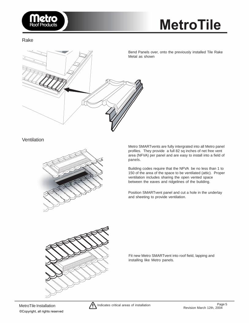
Metro SMARTvents are fully intergrated into all Metro panelprofiles. They provide a full 82 sq inches of net free ventarea (NFVA) per panel and are easy to install into a field ofpanels.
Building codes require that the NFVA be no less than 1 to150 of the area of the space to be ventilated (attic). Properventilation includes sharing the open vented spacebetween the eaves and ridgelines of the building.
Position SMARTvent panel and cut a hole in the underlayand sheeting to provide ventilation.
Fit new Metro SMARTvent into roof field, lapping andinstalling like Metro panels.
Page 5
Ventilation
©Copyright, all rights reserved

Revision March 12th, 2004MetroTile Installation Indicates critical areas of installation
Side-head Wall/Chimney/SkylightThe following details apply to any square cornered protrusions through a roof.
2. 3.
4. 5. 6.
7.
1.
Measure, cut, and fold up panel 2”from the back of the panel to thefront of chimney.
Cut a 45 degree angle as shownand fold tabs around chimney.
Cut and fold up panels 2” atsides of protrusion as shown.
Seal around perimeter offolded panels prior to attachingthem to chimney.
Install chimney saddle metal atback of chimney as shown.Extend Saddle metal a minimumof 4” past each side of chimney.
Seal under the saddle metalwhere it overlaps the panels.
8.
Install and seal ‘Z’-bar flashingmetal over folded sections asshown.
For severe weather conditions, the ‘Z’-bar can be scribed into the chimney.
Fold up nose of panel whereunderpan metal exits on top offield panels below.
An alternateflashingmethod is touse side-wallUnderpanmetal asshown. This
can then be counter flashed usingthe Metro Counter flashing metal orstandard ‘Z’-bar metal weather-proofed over the up stand of theside-wall underpan metal.
Page 6
©Copyright, all rights reserved

MetroTile Installation Indicates critical areas of installationRevision March 12th, 2004
The top course of panels requires a cut and bent panel tocomplete the ridge line.
Never cut the ridge panels before bending as theydeform slightly in the bending process and aredifficult to install. Deduct 1/2” from these measure-ments and apply to full panels. Mark both bendand cut lines for each panel.
Bend all ridge panels using Metro’s top bender.
Ridge Panels
2"
Page 7
The following steps should be followed to ensure a weathertight installation along the ridge.
Fasten one end of the cut ridge panel nose as shown.
“Bow” the panel at the center, and align the panel with correctinterlock location at the other end of the panel and fasten.
Push the ridge panel down against the lapped panel andand fasten.
1.
2.
3.
1.
2.
3.
©Copyright, all rights reserved

Revision March 12th, 2004MetroTile Installation Indicates critical areas of installation
PanelsPipe
Pipe Flashing
Tile Under-Pan
Felt paper
Install pipeflashing over‘Under-Pan’.
Cut a hole in thecovering panel to fitthe cone of the PipeFlashing.
to avoid adverse corrosion effects caused bydisimilar metals, COPPER and LEAD flashingsshould not be used with Metro roof products andaccessories
Dissimilar Metals
2.1.
3. 4.
Seal VentPipe aroundbottom of coneand around pipeflashing as shown.
Cut ‘Under-Pan’ flashingaround VentPipe asshown. Bend frontedge of ‘Under-Pan’over rear of underlapped panel.
Pipe Flashings - SMARTjack Method
The Metro 3-in-1SMARTjack is a moldable stone-coated roof flashing that can be used on most roof vent pipes, 1” to 3” in.dia. Apply sealant under 3-in-1 SMARTjack to keep it secured to panel beneth.
If vent location prevents SMARTjack 3-in-1 from being able to fold up andover the panels back flange, Use the Metro ‘Sandwhich’ method.
Pipe Flashings - Sandwhich Method
Page 8
©Copyright, all rights reserved

MetroTile Installation Indicates critical areas of installationRevision March 12th, 2004
Page 9
Short Course When a step or jog in the fascia is encountered, usually a“short course” of panels is required.
Install short course panels following a similar process toridge cuts.
Measure from the fascia to the short course batten andapply to a full panel. Bend up panel creating the std. 1”upturn.
Install as regular panel.
Always select the shortest length of “short course”to create your cut and bend process sections.
Seal the seams.
Install remaining panels of the full course.
©Copyright, all rights reserved

Revision March 12th, 2004MetroTile Installation Indicates critical areas of installation Page 10
TRIM CAP DETAILS
RIDGE CENTER CAPAt the center of a ridgeline, a small/short ridgecap as shown can bemade where cap piecesarrive from differentdirections.
RIDGE/GABLE ENDWhere the ridge intersects with agable end (rake), cut and fold theend disc as shown to follow theRake Channel sections previouslyinstalled.
HIP CORNERNotch & fold the end disc as shown toform a closed 3-dimensional end cap.Fit end disc to bottom hip corner withstitch screws and install balance of trimcaps up the hip. Nail each cap on eitherside of hip boards.
HIP/RIDGE INTERSECTIONInstall hip caps from the bottom using2 fasteners per trim cap. Overlaptrimcaps at hip/ridge intersection. Cutand fit the ridge capover both intersect-ing hip caps asshown.
Attach enddisc withstitch screws.
After installing trimcaps at intersections, seal cutedges and apply Metro basecoat and stone chip toprovide a complete stone coat finish.
©Copyright, all rights reserved

MetroTile Installation Indicates critical areas of installationRevision March 12th, 2004
3093 Industry StreetOceanside CA, 92054
PH.(760) 435-9842FX.(760) 435-1162
E-mail: [email protected]
Materials & Accessories:
General:MetroTile panels are produced fromAluminum-zinc alloy coated steelcomplying with ASTM A792.
Testing:MetroTile panels have been testedaccording to the toughest BuildingCode Standards. Testing has beenconducted to evaluate fire, wind,penetration, water infiltration, anddurability resistance. Informationregarding specific tests andapprovals can be obtained from MetroRoof Products.
Warranty:MetroTile panels carry a limitedwarranty for fifty years. This limitedwarranty is transferable and does notcover damage due to improperhandling or installation.
Packing and Storage:A pallet of MetroTile panels contains 20squares. Care should be taken tostore of MetroTile panels andaccessories. They should be placedunder a tarp, or placed in an area freefrom moisture and debris.
Dissimilar Metals:To avoid adverse corrosion effectscaused by dissimilar metals,COPPER and LEAD flashings shouldnot be used with Metro roof productsand accessories. (refer to MetroSMARTbrief #02004)
Roofing feltUnless local conditions requireotherwise, either one layer of type30, or two layers of Type 15 lb.roofing felt or equal should be usedwith MetroTile panels.
Roofing nailsCorrosion resistant .131” dia. x 2”long ring shank roofing nails areused to attach Metro roof productsand accessories.
Sealant/CaulkingOnly exterior grade urethane or(non-acidic) sealant should beused. Only use Metro Repair-kit(basecoat) to apply stone chips.
Finish coatingMinor scuffing of MetroTile panelscan be repaired with a Touch-Up kitfrom Metro Roof Products. Use theMetro adhesive (not caulking).Unfinished flashing materials canbe painted with durable acrylicaerosol paints. Colored aerosolpaints should never be sprayed onpanels or accessories made byMetro Roof Products.
2.5” Counter Flashing79” x 2.5”3.3 lbs.Stone Coated
Ventilation:Ensure proper attic ventilation asprescribed per local codes. Either SmartVents or Ridge venting can be installed toachieve adequate ventilation.
Other Items Needed:Caulk (sealant)DrillMetal snipsScrew GunMetro Cutter (optional)Nail gunRoofing nails (ring shank)Roofing feltHammerHand bendersTape measureCaulking gun
Side-Wall Underpan metal120” x 4”5 lbs.
Chimney Saddle60” x 16”6.75 lbs.
MetroTile52” x 16.5”5.5 lbs.20 per square
Barrel Cap Trim14.5” x 6”1 lbs.
Trim End Disc6” x 4”.15 lbs.
MetroTile SMARTvent52” x 14.5” x 3.5”10.5 lbs.Net Free Vent Area 82.5”
3.5” Fascia Metal79” x 3.5”2.5 lbs.Stone Coated
7” ‘W’ Valley 120”120” x 7”
Tile Rake Metal 120”120” x 2” x 1.75”2.1 lbs.
5” Fascia Metal79” x 5”3.75 lbs.Stone Coated
‘Z’-bar Metal79” x 2.5”3.5 lbs.Stone Coated
©Copyright, all rights reserved