Incipient surge detection in automotive turbocharger ...
14
Page 1 of 14 2019-24-0186 Incipient surge detection in automotive turbocharger compressors S. Marelli, P. Silvestri, V. Usai, M. Capobianco Università degli Studi di Genova Abstract Nowadays, turbocharging is a technique widely used to improve fuel consumption and exhaust emissions in automotive engines. Centrifugal compressors are typically adopted, even if an efficient engine integration is often restricted by surge phenomena. The focus of the present work is to describe an experimental analysis developed with the aim at characterizing and identifying compressor behavior in incipient surge conditions. The acoustic and vibrational operative response of two automotive centrifugal compressors has been experimentally analyzed on the test facility operating at the University of Genoa. Each compressor is characterized by a classical architecture and one of them is equipped with a “ported shroud”, which enlarges stable zone. Compressors characteristic curves have been measured under steady flow conditions for different levels of corrected rotational speed from the choking region to the surge line. Moreover, transient operations have been taken into account where, starting from a stable condition, surge phenomenon was generated progressively closing a valve positioned downstream the compressor or increasing rotational speed keeping fixed the circuit characteristics. Accelerometer and microphone signals have been acquired and analyzed both in the sub-synchronous contents and in higher frequencies range related to blade passage phenomenon. In addition, instantaneous compressor outlet pressure, turbocharger rotational speed and temperature (captured close to the rotor) have been recorded. Different signal processing techniques in time and frequency domain have been considered to analyze components and to separate the whole signal into individual source contributions to identify the system status. The obtained results provide an interesting diagnostic and predictive solution to detect compressor instabilities at low mass flow rate operating conditions. Introduction Nowadays, downsizing and turbocharging techniques are widely used to improve fuel economy in automotive engines. Centrifugal compressors are key components in the modern turbocharged Internal Combustion Engine (ICE) design and an efficient implementation is often restricted by the surge phenomenon. The prediction and the prevention of surge are relevant aspects to avoid unacceptable operating conditions and damaging problems [5, 6]. By further reducing the mass flow rate, rotating stalled flow patterns are triggered. In this case, one or more stalled flow cells can propagate along the impeller annulus, and thus the resulting pressure oscillations frequency is a fraction of the impeller rotational speed [1, 4]. Emmons et al. [1] presented an experimental investigation on compressor surge and stall propagation through a hot-wire anemometer system. It was observed that the whole compressor flow system may be unstable in the manner of a self-excited Helmholtz resonator. Fink et al. [2] investigated the turbocharger surge in a radial impeller-vaneless diffuser free-spool system. Measurements showed impeller stall at the inducer tips to be a key phenomenon in initiating surge. Yano [3] et al. studied the effect of pulsating flow on compressor performance through theoretical calculations and experiments to validate the model. The study of compressor instability is also extremely relevant for transient performance and boost pressure control purposes, as indicated by the numerous contributions available on the topics of modeling and model-based control [4]. The main focus on surge investigation is the analysis of the inception process and the origin of surge occurrence, in order to early predict the approaching of this undesired operating condition. Experimental investigation on compressor performance together with the analysis of the vibro-acoustic operational system response seems to give interesting diagnostic tools to correctly predict this phenomenon [7-12]. Munari et al. [7] performed experimental investigations in the stable and unstable operating conditions of an aeronautic turboshaft gas turbine axial-centrifugal compressor. In the paper the test field data are analysed showing the performance of the turbomachinery and its transient behaviour toward and during surge using pressure, temperature and mass flow sensors located in strategic positions along the circuit. In [8] the concept of “quasi-dynamic” pressure measurements is introduced in order to obtain compressor spectral maps describing the process of surge onset in a centrifugal blower. Kabral et al. [9] proposed a new method based on the full acoustic 2-port model for investigations of centrifugal compressor stall and surge inception. Marelli et al. [10] adopted a specific flexible circuit installed downstream the compressor to investigate the effect of circuit geometry on a turbocharger compressor performance with special reference to surge phenomenon. Instantaneous static pressures are measured in several locations upstream and downstream the compressor. Besides, dynamic sensors to measure noise and vibrations are also adopted. In [11] experimental results obtained from a T100 microturbine connected with different volume sizes are shown with special reference to surge operations. Ferrari et al. [12] presented a surge prevention technique for advanced gas turbine cycles carrying out a vibration analysis. The vibro-acoustic signal analysis showed a significant increase of energy content in specific frequency bands, not only during surge events, but also close to the unstable condition [13, 14]. This technique seems to be promising due to the adoption of not intrusive standard sensors, able to be easily implemented in the on board automotive diagnostic system. In previous works, high noise levels near the Helmholtz frequency were observed at compressor low mass flow rate levels, moving towards the undesired working region. Moreover, a significant signal content in the sub-synchronous range seems to be present close to the unstable condition and it may be related with rotating stall phenomenon [13]. Recently, the research approach based on vibro-acoustic surge precursors seems to be promising and complementary to other techniques based on compressor performance studies [7-12]. A turbocharger compressor was tested by the researchers of National Technical University of Athens [15], observing an increase in low
Transcript of Incipient surge detection in automotive turbocharger ...

Page 1 of 14
2019-24-0186
Incipient surge detection in automotive turbocharger compressors
S. Marelli, P. Silvestri, V. Usai, M. Capobianco
Università degli Studi di Genova
Abstract
Nowadays, turbocharging is a technique widely used to improve fuel
consumption and exhaust emissions in automotive engines.
Centrifugal compressors are typically adopted, even if an efficient
engine integration is often restricted by surge phenomena.
The focus of the present work is to describe an experimental analysis
developed with the aim at characterizing and identifying compressor
behavior in incipient surge conditions. The acoustic and vibrational
operative response of two automotive centrifugal compressors has
been experimentally analyzed on the test facility operating at the
University of Genoa.
Each compressor is characterized by a classical architecture and one of
them is equipped with a “ported shroud”, which enlarges stable zone.
Compressors characteristic curves have been measured under steady
flow conditions for different levels of corrected rotational speed from
the choking region to the surge line. Moreover, transient operations
have been taken into account where, starting from a stable condition,
surge phenomenon was generated progressively closing a valve
positioned downstream the compressor or increasing rotational speed
keeping fixed the circuit characteristics.
Accelerometer and microphone signals have been acquired and
analyzed both in the sub-synchronous contents and in higher
frequencies range related to blade passage phenomenon.
In addition, instantaneous compressor outlet pressure, turbocharger
rotational speed and temperature (captured close to the rotor) have
been recorded.
Different signal processing techniques in time and frequency domain
have been considered to analyze components and to separate the whole
signal into individual source contributions to identify the system status.
The obtained results provide an interesting diagnostic and predictive
solution to detect compressor instabilities at low mass flow rate
operating conditions.
Introduction
Nowadays, downsizing and turbocharging techniques are widely used
to improve fuel economy in automotive engines.
Centrifugal compressors are key components in the modern
turbocharged Internal Combustion Engine (ICE) design and an
efficient implementation is often restricted by the surge phenomenon.
The prediction and the prevention of surge are relevant aspects to avoid
unacceptable operating conditions and damaging problems [5, 6].
By further reducing the mass flow rate, rotating stalled flow patterns
are triggered. In this case, one or more stalled flow cells can propagate
along the impeller annulus, and thus the resulting pressure oscillations
frequency is a fraction of the impeller rotational speed [1, 4]. Emmons
et al. [1] presented an experimental investigation on compressor surge
and stall propagation through a hot-wire anemometer system. It was
observed that the whole compressor flow system may be unstable in
the manner of a self-excited Helmholtz resonator. Fink et al. [2]
investigated the turbocharger surge in a radial impeller-vaneless
diffuser free-spool system. Measurements showed impeller stall at the
inducer tips to be a key phenomenon in initiating surge. Yano [3] et al.
studied the effect of pulsating flow on compressor performance
through theoretical calculations and experiments to validate the model.
The study of compressor instability is also extremely relevant for
transient performance and boost pressure control purposes, as
indicated by the numerous contributions available on the topics of
modeling and model-based control [4].
The main focus on surge investigation is the analysis of the inception
process and the origin of surge occurrence, in order to early predict the
approaching of this undesired operating condition.
Experimental investigation on compressor performance together with
the analysis of the vibro-acoustic operational system response seems
to give interesting diagnostic tools to correctly predict this
phenomenon [7-12]. Munari et al. [7] performed experimental
investigations in the stable and unstable operating conditions of an
aeronautic turboshaft gas turbine axial-centrifugal compressor. In the
paper the test field data are analysed showing the performance of the
turbomachinery and its transient behaviour toward and during surge
using pressure, temperature and mass flow sensors located in strategic
positions along the circuit. In [8] the concept of “quasi-dynamic”
pressure measurements is introduced in order to obtain compressor
spectral maps describing the process of surge onset in a centrifugal
blower. Kabral et al. [9] proposed a new method based on the full
acoustic 2-port model for investigations of centrifugal compressor stall
and surge inception. Marelli et al. [10] adopted a specific flexible
circuit installed downstream the compressor to investigate the effect of
circuit geometry on a turbocharger compressor performance with
special reference to surge phenomenon. Instantaneous static pressures
are measured in several locations upstream and downstream the
compressor. Besides, dynamic sensors to measure noise and vibrations
are also adopted. In [11] experimental results obtained from a T100
microturbine connected with different volume sizes are shown with
special reference to surge operations. Ferrari et al. [12] presented a
surge prevention technique for advanced gas turbine cycles carrying
out a vibration analysis.
The vibro-acoustic signal analysis showed a significant increase of
energy content in specific frequency bands, not only during surge
events, but also close to the unstable condition [13, 14]. This technique
seems to be promising due to the adoption of not intrusive standard
sensors, able to be easily implemented in the on board automotive
diagnostic system.
In previous works, high noise levels near the Helmholtz frequency
were observed at compressor low mass flow rate levels, moving
towards the undesired working region. Moreover, a significant signal
content in the sub-synchronous range seems to be present close to the
unstable condition and it may be related with rotating stall
phenomenon [13].
Recently, the research approach based on vibro-acoustic surge
precursors seems to be promising and complementary to other
techniques based on compressor performance studies [7-12].
A turbocharger compressor was tested by the researchers of National
Technical University of Athens [15], observing an increase in low

Page 2 of 14
frequency energy content below rotational frequency (sub-
synchronous frequency contents) through microphones. Therefore, the
RMS value of the sub-synchronous part of the spectrum was proposed
as a parameter to distinguish compressor operating conditions. In [16,
17], the Authors developed significant studies to find stall or surge
precursors starting from turbocharger vibro-acoustic signals. A six
axial and one centrifugal compressor stages were tested highlighting a
sub-synchronous content in the spectrum map of the accelerometers
mounted in correspondence of the axial stages when the throttle valve,
used to control external circuit characteristic curve, was nearest to the
closed position.
In general, the significant low frequency noise and vibration level at
low mass flow rates are a well-recognized problem of the centrifugal
compressors and it well worth to deep these aspects for early
identification of surge condition.
In the work here presented, a method to investigate surge phenomenon
of turbocharger centrifugal compressors is proposed, mainly based on
vibro-acoustic response signal. The aim of the activity is to detect an
incipient surge condition in a reliable way, avoiding false positives.
The experimental campaign was developed on the test facility
operating at the University of Genoa (UNIGE), considering different
operating points ranging from the choking region to the surge line, of
two compressors characterized by different size. During the tests,
pressure signals and instantaneous turbocharger rotational speed are
measured using high frequency response transducers together with
vibro-acoustic measurements.
A preliminary analysis has been performed to better understand the
frequency contents of the acquired signals and to identify the more
suitable sensors for diagnostic purpose.
The frequency characteristics of the vibro-acoustic signals were
obtained by computing a “Fast Fourier Transform” (FFT) and
discussed at different operating conditions from stable to unstable
conditions.
In addition, the information of a fast response pressure probe mounted
downstream the compressor has been analyzed and compared with the
others instantaneous recorded signals.
Sub-synchronous spectrum has been evaluated highlighting a
significant operational content close to the Helmholtz frequency of
inlet and outlet compressor circuits previously identified with a
specific experimental activity. Moreover, the sub-synchronous
characteristics, probably associated to the rotating stall, has been
considered.
In addition, high frequency range has been also analyzed to detect the
intensification of unusual frequency contents in the response signal
while surge condition is approaching. This effect is maybe related to
other sources interacting with typical compressor operational
phenomena like blade passage. A method based on high frequency
signal demodulation is used to better identify sub-synchronous
phenomena as rotating stall, not always easily detectable through a
direct analysis of the sub-synchronous spectra.
Signal energy levels have been calculated and their trend on
compressor characteristic curves has been analyzed on a wide
operative range with particular attention to the low mass flow rate
region.
This information could be used to find precursors of surge occurrence
to be used as control data (i.e., an on/off signal for a bleed valve)
implemented in an on board engine control system.
Experimental set-up
The experimental activity was developed on two different turbocharger
compressors: a turbocharger IHI RHF3 adopted for downsized spark
ignition engines, and a turbocharger Borg Warner EFR 7670-C for
heavy duty diesel engines. The tested compressors are characterized
by a vaneless diffuser, different size, and the Borg Warner EFR 7670-
C is equipped with a ported shroud to enlarge flow stability [18]. In
Table 1, the main geometric characteristics of the tested turbochargers
are reported.
Table 1 – Turbochargers geometric characteristics
Turbocharger type Borg Warner IHI
Compressor impeller inlet
diameter
78.6 mm 40 mm
Turbine impeller outlet diameter
69.5 mm 33 mm
N° of compressor blades 14 10
N° of turbine blades 8 11
The experimental activity was developed on the turbochargers test
bench of the University of Genoa (Figure 1), fully described in
previous papers [19-21]. Three screw compressors supply a total mass
flow rate of 0.6kg/s at a maximum pressure of 8bar. The turbine inlet
temperature can be controlled in order to develop test in cold and hot
condition (up to 750°C, depending on the size of tested turbocharger).
The compressor inlet pressure can be controlled by regulating systems
or can directly work under ambient pressure condition (AF, in Figure
1). An automatic data acquisition system allows measurements of
thermodynamic parameters to be performed at different measuring
sections.
Average and instantaneous static pressures were measured through
piezoresistive transducers (accuracy of ±0.15% of full scale). K type
thermocouples (accuracy ±1.5°C) and platinum resistance
thermometer (Pt 100 Ohm class A, accuracy of ± 0.15°C + 0.2% of
measured value) were used to measure air temperature. Besides, an
exposed junction K type thermocouple, placed close to the inducer of
IHI turbocharger, was used to better appreciate the temperature rise
and fluctuation close to unstable zone. An eddy current probe mounted
close to the compressor wheel was used for turbocharger rotational
speed measurement (accuracy of ±0.009% of full scale). Compressor
mass flow rate was measured using a thermal mass flow meter
(accuracy of ±0.9% of measured value and ±0.05% of the full scale).
Instantaneous pressure and turbocharger rotational speed were
measured with high-frequency response probes and two high speed
data acquisition cards.

Page 3 of 14
Figure 1. The turbocharger test facility of the University of Genoa.
Vibration and acoustic measurements were conducted using a
dedicated data acquisition system, which allows to acquire 16 different
channels with frequencies up to 204.8kHz sampling rate per channel,
at the same time (Table 2). Structural measurements were performed
using mono accelerometers located at the compressor inlet (called a:1,
Table 2) and outlet (called m:2, Table 2). Sensor frequency response
allowed to investigate signals components up to 10kHz. Three micro
mono axial accelerometers (with a resonance frequency higher than
55kHz) were mounted on the compressor housing in radial (X),
tangential (Y) and axial (Z) direction with respect to the volute (called
c:1, Table 2 and Figure 2 on left side). These probes allow to extend
vibration investigation to the higher frequencies, in the range of blade
pass frequency (BPF) phenomena.
Acoustic measurements were carried out with pre-polarized
microphones with range between 2 and 50kHz of dynamic response.
When the filter (AF, in Figure 1) is adopted, radial oriented
microphones (with reference to the duct) equipped with ellipsoidal
windscreen was assembled at the compressor inlet in order to capture
acoustic contribution to dynamic phenomena related to the wave
propagation in the feeding line (called asp:1, Table 2). Radial and axial
oriented microphones were positioned near compressor housing in
order to capture vibro-acoustic radiated noise from the turbocharger
(called comp:1, b&k:1, Table 2 and Figure 2 on right side).
Besides, a high-frequency response pressure transducer was placed
downstream the compressor to capture inflow pressure time history
(called kul:1, Table 2).
Table 2. List of measured vibro-acoustic variables.
Location Variable Description
c:1
c:1:+X Radial acceleration on compressor
housing
c:1:+Y Tangential acceleration on compressor housing
c:1:+Z Axial acceleration on compressor housing
a:1 a:1:+X Acceleration on inlet compressor line
m:2 m:2:+X Acceleration on outlet compressor line
b&k:1 b&k:1:+S Acoustic pressure on compressor housing (radial oriented)
comp:1 comp:1:+S Acoustic pressure on compressor housing
(axial oriented)
asp:1 asp:1:+S Inlet filter acoustic pressure
kul:1 kul:1:+S Inlet flow pressure outlet compressor
temp:1 temp:1 Temperature fluctuations in the
compressor inlet
Figure 2. Detail of the three accelerometers on the compressor housing (the
arrows indicate the measurement directions) on left side; microphones close to
IHI compressor housing on right side.
The experimental tests were conducted by controlling the turbine
power to drive the compressor rotational speed to a desired value. The
compressors performance is evaluated over an extended range, using
the motorized valve shown in Figure 1 to control the position of the
operating point on the characteristic curve. The turbocharger shaft
speeds were varied up to 130krpm for Borg Warner and to 220krpm
for IHI. Acquisitions were developed under steady flow conditions to
define a set of different stable operating points on the compressors
characteristic curve for different corrected rotational speeds (ncr)
defined as
n𝑐𝑟 =𝑛∙√𝑇0
√𝑇𝑇1
where:
n is turbocharger rotational speed
T0 is reference condition (equal to 293.15K)
TT1 is compressor inlet total temperature
Then, the motorized valve was progressively closed to induce surge in
the compressor. To detect the transition from stable to unstable
operations, i.e. the position of the surge line, the compressor outlet
pressure was recorded as the reference signal, monitoring its frequency
spectrum, and detecting the harmonics associated with the surge
phenomenon [10].
Besides, a very slow transient operation in compressors speed was
analyzed, maintaining the circuit (i.e., the motorized valve) in the same
condition.
Analysis on sensor frequency contents and
harmonic response of the circuit
Before performing a purely diagnostic analysis, the dynamic behaviour
of both turbochargers were experimentally investigated in the stable
operating region to obtain the vibro-acoustic responses in safe
operating conditions.
Frequency analysis allowed to define signal spectrum contents and a
preliminary identification of the sources was also performed aiming to
classify the principal contributions in the operational system
responses. Moreover, the sensors ability to recognise a specific source
based on the typology (structural, acoustic, fluid-dynamic) and the
measurement position were analyzed.
The aim of this preliminary activity was to improve the monitoring
system in order to identify which kind of response is more useful and
suitable to identify an incipient surge condition.
The rotor-dynamic behavior of each compressor is very similar, due to
the same radial hydrodynamic floating ring bearings adopted, which
AF Air Filter LM Laminar Flow Meter
AH Air Heater PC Pressure Control
APH Air Pre-Heater PG Pulse Generator
AR Air Reservoir SC Screw Compressor
C Compressor T Turbine
LC Lubricating Circuit TM Thermal Mass Flow
Meter

Page 4 of 14
are fundamental in defining the dynamic characteristic of a rotating
machine [22, 23].
IHI turbocharger stable behavior was already analyzed and reported in
[10] and its operational response is mainly related to residual
unbalance, whirl and whip instabilities in hydrodynamic bearings and
blade pass phenomena (both of compressor and turbine). Moreover,
broadband contents related to fluid-dynamic phenomena and system
resonances have been found in some operating conditions [10].
In the following figures, Borg Warner turbocharger stable operational
response is analyzed at a constant corrected rotational speed of 80krpm
close to the maximum efficiency operating point. Figure 3 reports two
acoustic autopower spectra recorded with microphones placed at the
filter section (red trace) and close to the compressor volute (green
trace). In Figure 4, the autopower spectra of a pressure signal measured
downstream compressor (red trace) and of a structural signal (green
trace) recorded through an accelerometer installed on the compressor
housing are shown. For each signal, the obtained function describes
the distribution of power into frequency components. The autopower
algorithm allow to identify both random and deterministic
components. The presence of synchronous 1X component related to
residual unbalance (black dashed line cursor at 1357Hz) is apparent.
The 2X components (black dashed line cursor at 2714Hz) can be
detected only for the spectra of accelerometer and pressure signals
downstream the compressor, maybe due to system nonlinearities and
to a resonant behavior able to amplify the energetic content in the
system responses.
Figure 3. Example of microphone signals spectra at the inlet filter (red trace, at the bottom) and at compressor housing (green trace at the top) for ncr = 80krpm,
in maximum efficiency condition.
Figure 4. Example of pressure signal spectra measured downstream
compressor (red trace, at the bottom) and accelerometer signal spectra on
compressor housing (green trace, at the top) for ncr = 80krpm, in maximum efficiency condition.
The sub-synchronous content at 574Hz due to the floating ring radial
bearings is mainly present in the accelerometer signal (black dotted
cursor). This contribution is more prominent than the one related to
residual unbalance underlining how bearings are significant in the
overall turbocharger vibrational response. The floating ring radial
bearing content is well detectable in both microphone spectra, while it
is almost absent in pressure signal downstream the compressor
denoting that this phenomenon does not seem to involve fluid domain.
In high frequency range, compressor BPF is detectable for all acquired
signals (blue dashed line cursor), while turbine BPF (magenta dashed
line cursor) can only be seen in autopower spectra of microphone close
to the turbocharger and of accelerometer on the compressor housing.
In some cases, peaks are detectable at a frequency close to the BPF and
may be related to mechanic sources in low frequency (synchronous
component 1X e floating ring radial contribution) that interact with the
blade pass phenomenon [24].
Some marked frequency contents at low frequency are present in the
microphone spectrum at the filter inlet section (see blue ellipse in
Figure 3 and green dashed line cursor at 205Hz), differently from the
accelerometer signals. These contributions may be related to circuit
acoustic modes and to wave dynamics phenomena in the inlet duct.
The system structural properties at these frequency levels seems to
filter these contributions reducing their energy in structural responses.
In Figure 5 the spectrum of the accelerometer placed on the compressor
housing in radial direction is reported for IHI turbocharger at a constant
corrected rotational speed of 90krpm close to the maximum efficiency
operating point. The frequency components show a strict analogy with
those detected for Borg Warner turbocharger. Also in this case, the
frequency contents may be easily associated to the principal system
sources (dashed line black cursor at 1505Hz for 1X, blue and magenta
cursors respectively for compressor and turbine BPFs, dotted line
black cursor at 437Hz and its second order for whirl/whip in radial
bearings).
For IHI turbocharger, the contributions related to the bearings
instability are much more apparent and dominant maybe related to the
lower rotor inertias, which induce higher instability in the bearings [22,
23]. Also for IHI turbocharger high frequency peaks near BPFs related
to low frequency sources (1X, whirl/whip) interacting with high
frequency ones are evident [24].
10000 200005000 15000 25000
Hz
comp:2:S (CH7)
0.00
0.02
Pa
1357 9519 13561
572
205
AutoPower comp:2:S
10000 200005000 15000 25000
Hz
asp:1:S (CH6)
0.00
0.02
Pa
1357 9519 13561
572
205
AutoPower asp:1:S
0 10000 200005000 15000 25000
Hz
c:1:+X (CH1)
0.0
0.1
0.2
g
1357
574
9512 13561
AutoPower c:1:+X
0 10000 200005000 15000 25000
Hz
kul:2:S (CH11)
0
4
8
12
16
Pa
1357
574
9512 13561
AutoPower kul:2:S

Page 5 of 14
Figure 5. Example of compressor housing accelerometer spectrum – IHI
turbocharger - for ncr = 90krpm, in maximum efficiency condition.
Synchronous and sub-synchronous components related to residual
unbalance and bearing phenomena are not evident in the accelerometer
signal at the compressor inlet section. This may be justified by the fact
that elastic junctions have been used for the connection of the
compressor with the test bench pipes so that, at these frequencies, they
are structural uncoupled (see Figure 2).
Therefore, no significant structural path is available allowing
propagation of structural components from turbocharger to the pipe
line. Moreover, it seems that these mechanical sources have only a
slight interaction with fluid and so fluid-dynamic path also is not
available.
Surge is an unstable operation state, characterized by components in
sub-synchronous domain (rotating stall and broad band phenomena
that excite pipe line acoustic modes) and in high frequency domain
(BPF) [4, 7, 11]. For an easy early detection, it seems useful to analyze
high sensitivity signal to fluid-dynamics phenomena instead to
mechanical ones. System transmissibility seem fundamental as it can
attenuate or amplify the responses to certain sources. As reported
hereafter, downstream compressor pressure sensor and microphone
located in correspondence of the filter seem to be more useful for this
purpose.
In the proposed paper, the acoustic Frequency Response Functions
(FRF) of inlet and outlet compressor sections were identified to
validate whether this information can help the interpretation of the
system behavior in the proximity of unstable operating condition.
The excitation was introduced using an electromechanical shaker
instead of the compressor. The exciter head was positioned
alternatively in the inlet and outlet pipe line in correspondence of the
connection section of the compressor. The shaker was driven in sine
mode with variable frequency and allowed to generate plane waves
inside the ducts.
FRFs were evaluated between microphone response signal in a specific
point of the analyzed pipe line, and a reference signal correlated with
the generated acoustic excitation in the duct. In this case, the electrical
signal driving the external sources was selected as the reference.
During the investigation on the surge onset, the compressor interacts
with the system differently from the shaker, introducing different
boundary conditions in the pipe line and leaving a coupling between
the intake and outlet circuit that is totally absent in the case of shaker
tests. Furthermore, the use of the shaker does not consider the
contribution of the compressor related to its operating condition, which
could significantly influence the dynamic response of the whole
system [9].
Despite these considerations, a comparison between the FRFs
obtained through the exciter and the system operational response
spectra is performed to improve the system response analysis in order
to assess possible correlations.
Figure 6 shows the acoustic FRFs obtained for the inlet (on the top)
and outlet (on the bottom) lines in the 3-200Hz range. In the case of
the outlet circuit, a significant sensitivity of the system dynamics
related to the fractional opening of the throttling valve was observed.
In particular, red and green lines are respectively referred to the fully
open and closed position of the throttle valve. The functions trends are
well defined, and different peaks at certain frequencies maybe
corresponding to possible acoustic modes of the system can be easily
identified.
The peaks seem to be related to the propagation phenomena of
perturbations in the ducts for both inlet and outlet sections. The
frequency values are fairly near to the Helmholtz frequency and higher
multiple frequencies, defined as
f𝐻 =𝑎∙√𝐴
2𝜋√𝑙∙𝑉
where:
a is the speed of sound
l and A are respectively the equivalent length and cross-sectional area
of the duct
V is the system air volume [4].
Figure 6. Identification of the inlet circuit (on the top), outlet pipe (on the
bottom) for two extreme values of throttle valve opening.
Surge identification - analysis of instantaneous
signals
0 10000 20000 300005000 15000 25000
Hz
c:1:+X (CH1)
0
g
1505 14981
16489437
AutoPower c:1:+X
10 1003 4 5 6 7 8 9 20 30 40 50 60 70 80
Hz
10e-3
100e-3
1
10
6e-3
20e-3
30e-3
50e-3
70e-3
200e-3
300e-3
500e-3
700e-3
2
3
5
7
Pa
/V
14.9 29 45 66 86
FRF - inlet circuit
10 1003 4 5 6 7 8 9 20 30 40 50 60 70 80
Hz
100e-3
1
10
70e-3
200e-3
300e-3
400e-3
600e-3
2
3
4
6
20
Pa
/V
12 29 41 55 70 84 101 117
130
147
25
80
fully open position - V=0%closed position - V=100%
FRF - outlet circuit

Page 6 of 14
For incipient surge detection, the vibroacustic compressor response for
both turbochargers is initially analysed for different values of
compressor mass flow rate, considering a fixed compressor rotational
speed. This technique allows to analyse different operating points on
the compressor map and to observe transition from stable operation to
unstable conditions. FFT analysis has been used to detect how
frequency signal contents in the system responses change from a stable
to a near unstable condition. Hereafter, the results are subsequently
presented with a particular emphasis in the sub-synchronous frequency
range and at high frequency value in correspondence of the blade pass
frequency (BPF).
As reported in literature [10-12, 15-17], the sub-synchronous
frequency range are attractive for the surge detection because it does
not take into account contents due to vibrational sources such as
residual unbalance or other phenomena associated to the turbocharger
rotational speed and higher multiples.
There is a sub-synchronous mechanicals contribution due to the
floating ring radial bearings adopted in both turbochargers, which is
clearly identifiable as it depends mainly on the rotational speed and
can be easily separated and removed through an order-stop filter [10].
Therefore, its energy (RMS value) is strictly related to fluid
characteristics and it is more sensitive approaching the incipient surge
condition. In Figure 7, the auto-power spectra acoustic response for 5
different valve openings from far (trace no. 1) to immediately above
surge event (trace no. 5) for the Borg Warner compressor (ncr =
80krpm) are shown. Microphone signal positioned along the filter has
been considered as it contains information regarding the circuit fluid
dynamic phenomena and the compressor operating condition.
The FFT analysis highlights that low-frequency contents (up to 300Hz)
result in a significant increase of their energy level, when approaching
surge (blue elliptical marker on trace no. 5). This effect seems to be
related to the surge occurrence broadband source due to not optimal
flow condition in the compressor exciting system acoustic resonance (
dashed line black cursors, Figure 7) causing significant peaks in the
response system signal.
Figure 7. Auto-power spectra of the microphone at the filter section for ncr =
80krpm. Sub-synchronous vibration contents highlighted in the blue ellipse (frequency axis in logarithmic scale) – Borg Warner turbocharger compressor.
For each trace it is noticeable the presence of the synchronous
contribution 1X (blue dotted cursor at 1360Hz), characterized by more
significant intensity in the last stable operating point probably due to
anomalous outflow condition in the rotor which generates an
additional unbalance in the system [4]. Besides, frequency components
close to the 1X (orange ellipse in Figure 7) related to new phenomena
that arise in the system approaching the incipient surge condition.
For traces no.4 and 5, a peak can be observed close to 400Hz frequency
(green dashed line cursor in Figure 7) probably related to the rotating
stall of the compressor. This aspect will be later on discussed by
correlating this contribution in the sub-synchronous field to the blade
passage within an analysis in high frequency signal contents.
In Figure 8 (on the top) the envelope trace of the previous spectra
calculated in stable conditions (shown in red) and the spectrum of the
acoustic response in deep surge (shown in green) are reported. The
envelope trace highlights the significant peaks of all operational
responses before reaching the unstable condition. In Figure 8 (on the
bottom) the same traces for the IHI turbocharger are reported for a
corrected rotational speed level of 118krpm.
Figure 8. Envelope auto-power spectrum trace evaluated referring to the
previous stable spectra (left side - primary axis) and auto-power spectrum in deep surge condition (right side - secondary axis) - (Borg Warner compressor,
ncr = 80krpm on the top; IHI compressor, ncr = 118krpm on the bottom).
For each tested compressor, common peaks close to low frequency
domain (up to 300Hz) can be observed for the envelope and the deep
surge spectra.
Slight variations in the frequency contents of the system operational
response when the compressor is operating in a stable or deep surge
condition can be highlighted. It seems that some dynamic properties
and some specific natural frequencies, that cause system operational
response, are not significantly influenced by a change of compressor
operating condition.
However, the energy contents at certain frequencies can instead be
very sensitive to changes in the operating condition of the machine.
For both compressors the signal amplitude is more significant in deep
surge condition (see different range in the two secondary axes).
Slight differences in operating frequencies can be observed when
comparing the spectra of the two turbochargers due to a low sensitivity
10 100 10005 6 7 8 9 20 30 40 50 60 7080 200 300 400 500 700
Hz
1
2
3
4
5
0.12
Pa
4341360
14.87.1 28 43 65 87
10 100 10003 4 5 6 7 8 20 30 40 50 60 80 200 300 400 600 2000
Hz
asp:1:S (CH6)
0.0
0.1
Pa
0
1
2
3
Pa
14.8 146228 45 73 118
1360
2057.0 286
AutoPower asp:1:S envelopeAutoPower asp:1:S deep_surge
10 100 10003 4 5 6 7 8 20 30 40 50 60 80 200 300 400 600 2000
Hz
asp:1:S (CH6)
0.0
0.1
Pa
0
1
Pa
13.8 208827 46 71 120
2176
7.0 194 291
AutoPower asp:1:S envelopeAutoPower asp:1:S deep_surge

Page 7 of 14
of the vibro-acoustic characteristics of the entire system with respect
to the compressor.
In the case of a deep surge, low frequency component is highlighted in
the spectrum at 7.0Hz for IHI turbocharger. In this operating condition,
the periodic reversal flow could excite low frequency modes not
receiving enough energy in stable operation.
For the Borg Warner turbocharger, the operating envelope (on stable
operating points) and deep surge spectra are calculated for further
levels of corrected rotational speed (ncr = 50, 65, 95 and 118krpm). For
each iso-speed level, a low dependence of the frequency contents is
confirmed by changing the mass flow rate.
Besides, the operational response spectra for different levels of
rotational speed exhibit similar trends in the low frequency range (up
to 300Hz) with the corresponding peaks at similar frequency values.
This seems to highlight a low dependence on the nature of the
responses (in terms of frequency contents), hence on the dynamic
properties of the system for a change in the compressor rotational
speed (Figure 9).
Figure 9. Envelope auto-power spectrum trace evaluated on stable spectra (left
side - primary axis) for Borg Warner turbocharger (on the top) and (auto-power
spectrum in deep surge condition for 5 rotational speed levels (on the bottom).
An invariance in terms of the characteristic frequencies of the system
response below 300Hz is observed for each operating conditions and
for both considered turbochargers.
In the field of sub-synchronous frequencies, it is possible to identify
other frequency bands characterized by a modified energy content,
significantly when the compressor approaches a surge condition.
At higher frequencies (0.5-1X range) a high peak density can be
observed probably due to the pipe line acoustic modes and to the
compressor operating condition.
A global energy trend at higher frequency levels is not always suitable
to detect when the compressor approaches an unstable operating
condition.
If the previous operational spectra (Figures 7-9) are compared with the
FRF obtained through the harmonic response of the circuit (Figure 6),
a good agreement may be found on the frequencies peak for both
functions (i.e., acoustic modes of the line identified by shaker and
operational responses in different compressor operating conditions).
The low frequency operational content seems to be highly dependent
on the compression line characteristics, with particular reference to the
inlet circuit and not to the compressor type and operating conditions.
The frequency values are close to the calculated Helmholtz frequency
and higher multiple frequencies (blue cursors in fig. 6 at 14.9, 29, 45,
66, 86 Hz).
Therefore, the experimental investigation on the pipe line response
seems important in the absence of the compressor and in the condition
of zero mass flow rate, to obtain information on the signal
contributions which can provide useful diagnostic information to
identify the incipient surge. In Figure 10, the measured operational
spectra for the sub-synchronous frequency range (1X blue dashed
cursor at 1360Hz) of the accelerometer mounted on the Borg Warner
compressor inlet are shown for the five previously considered
operating points at ncr = 80krpm.
Figure 10. Accelerometer signal spectra evaluated for ncr = 80krpm (from 0 to
4 operating points, i.e. from the maximum flow condition towards the surge
occurrence) – Borg Warner turbocharger
The contributions in the vibrational response seem not relevant with a
slight sensitivity to the surge up to 40Hz. A more prominent sensitivity
can be observed at higher frequencies (> 40Hz) probably related to the
dynamic properties of the system which cause the measured structural
responses. A significant increase in structural signal energy was
observed in a frequency range close to the 0.5X-1X range, where the
spectra trends change with an increase in energy content passing from
operating point 1 to 5, i.e. from the maximum flow condition towards
the surge occurrence. Structural signals measured at the compressor
housing highlight a worst sensitivity in identifying the surge
occurrence in the field of sub-synchronous frequencies, maybe due to
the presence of marked mechanical contributions which dominate the
effects of fluid dynamic response [10]. If the mechanical contributions
are properly removed, a diagnostic information suitable in the high
frequency field can be achieved.
For each compressor, the signals contents were taken into account for
diagnostic purposes, even during a surge transient. To observe the
transition from stable to unstable condition, the operational responses
were analysed during a turbocharger run up, increasing the compressor
rotational speed for the same position of the throttle valve (i.e., same
external characteristic curve of the circuit).
The transient investigation was run in a sufficiently slow manner to
reproduce a sequence of steady operating condition of the system.
Therefore, acquired signals represent a sequence of working points
characterized by a fixed valve position for each rotational speed value.
In Figure 11, the results are reported for a run-up starting from a
rotational speed of 60krpm for Borg Warner compressor: the
beginning of deep surge occurs at a rotational speed of about 92krpm.
The time-frequency analysis on the signal spectrum was conducted to
evaluate the instant of the surge inception, confirming that sub-
synchronous content is more significant for the surge detection. Figure
11 shows time-frequency analysis through a zoomed color-map of
10 1003 4 5 6 7 8 9 20 30 40 50 60 7080 200 300 400 500
Hz
asp:1:S (CH6)
0.1
0.2
0.3
0.4
0.5
0.6
Pa
14.8 28 45 68 95 2057.0 286
AutoPower asp:1:S envelope 050krpmAutoPower asp:1:S envelope 065krpmAutoPower asp:1:S envelope 080krpmAutoPower asp:1:S envelope 095krpmAutoPower asp:1:S envelope 118krpm
10 1003 4 5 6 7 8 9 20 30 40 50 60 7080 200 300 400 500
Hz
asp:1:S (CH6)
2.0
4.0
6.0
8.0
Pa
14.8 28 45 68 95 2057.0 286
AutoPower asp:1:S deep_surge 050krpmAutoPower asp:1:S deep_surge 065krpmAutoPower asp:1:S deep_surge 080krpmAutoPower asp:1:S deep_surge 095krpmAutoPower asp:1:S deep_surge 118krpm
10 100 10003 4 5 6 7 8 20 30 40 50 60 80 200 300 400 600 2000
Hz
a:1:+Z (CH5)
0.00
0.01
0.02
0.03
g
1093.2
1360
86657
735
153 309 461
AutoPower a:1:+Z 1AutoPower a:1:+Z 2AutoPower a:1:+Z 3AutoPower a:1:+Z 4AutoPower a:1:+Z 5

Page 8 of 14
acoustic pressure signal, measured at the filter section. The horizontal
(x) and vertical (y) axis represent the frequency content and the time,
respectively. The amplitude is related with the color intensity with
reference to the color-bar. Low frequency components (red dashed line
cursors in Figure 11) highlight a significant variation together with an
energy content rise during the transient operation approaching the
surge condition.
Figure 11. Time frequency analysis of microphone signal at the filter section
during surge transient operation (zoomed map range 3-1000Hz).
For better identify the most significant contents of the system response
during transient, the average function of all measured spectra was
assessed. In this function, the contents at a specific frequency common
for each spectrum are apparent, while the variable ones are not
detectable. Figure 12 shows the trend of the average spectra for each
compressor and in both cases the presence of very sharp peaks
indicates the existence of stable contributions that remain at constant
frequencies during the run up.
As under steady state investigation, it is possible to note significant
components in the acoustic responses, which remain at a fixed
frequency value during the transient for both compressors. This aspect
highlights the significant influence of the circuit on the operational
response.
The frequency contents evaluated in the transient investigations
present the same behavior of steady state, so linked to the Helmholtz
frequency and its multiples.
Figure 12. Average spectrum function of the acoustic response at the inlet
section during transient investigation (red line - Borg Warner compressor, green
line – IHI compressor).
A similar behavior can be observed for the microphone signal located
close to the compressor housing (Figure 13). In this case, the
contributions related to the rotational speed are apparent, such as the
sub-synchronous of the floating ring radial bearings (see orange arrow)
and synchronous of residual unbalance (see green arrow). In the low
frequency band, contributions related to the pipe line characteristic can
be observed in the compressor housing microphone signal. The
structural responses (Figure10) are not characterized by low frequency
contents. An acoustic path could be assumed between the inlet filter
and the microphone located close to the compressor housing.
Figure 13. Time frequency analysis at the compressor housing of the
microphone signal during transient operation (zoomed map range 3-1000 Hz).
Vibration data were recorded through a high sample frequency value
(100 kHz) to investigate vibrational and acoustic response in high
frequency domain close to the blade pass frequency (BPF).
Figure 14 shows high frequency components of the auto-power spectra
measured on the Borg Warner compressor housing in radial direction
from stable (operating point 1, higher spectrum) to incipient surge
(operating point 5, lower spectrum) conditions for ncr = 80krpm
(operating point 4, middle spectrum).
It is possible to note that the frequency peak associated with the BPF
(dotted blue line cursors at 9.4kHz and 18.8kHz for the BPFs without
or with splitter blades, Figure 14) becomes less marked when moving
from point 1 to point 5. Near unstable conditions, BPF component
seems to lose energy and, at the same time, new contributions rise
related to fluid-dynamic phenomena linked to the incipient surge.
Figure 14. High frequency detail of the radial acceleration auto-power spectra
evaluated on the compressor housing in three different operation conditions.
In the last stable condition before incipient surge, significant energy
content is observed in the 6X-7X frequency band (8079-9425Hz, see
left black dashed line and blue dotted line cursors). In this range it is
possible to identify a main contribution at 9019Hz (cyan dashed
cursor) which is a frequency that differs from the BPF by a value equal
to 9425-9019 = 406Hz, lower than the synchronous frequency
(406Hz<1X = 1346Hz).
In the spectrum, a side band near the main peak corresponding to the
BPF arises and it is clearly identifiable. This could lead to the
hypothesis of the rise of a new phenomenon that interacts with the
blade passage characterized by a sub-synchronous characteristic
frequency of 406Hz (<1X) [24].
10 100 10003 4 5 6 7 8 9 20 30 40 50 60 7080 200 300 400 500 700
Hz
asp:1:S (CH2)
10
20
30
40
50
60
70
5
15
25
35
45
55
65
s
0.50
0.00
Pa
7.2 15.9 27.6 46.1 68.6 94.7 225
10 1003 4 5 6 7 8 9 20 30 40 50 60 70 80 90 200 300
Hz
0
10
20
5
15
25
Pa
28.0 45.5 68.5 93.5 116.57.6 15.7
135.3
190.0 246.1
225.6
AutoPower asp:1:S - Borg WarnerAutoPower asp:1:S - IHI
10 100 10003 4 5 6 7 8 9 20 30 40 50 60 7080 200 300 400 500 700
Hz
comp:2:S (CH3)
10
20
30
40
50
60
70
5
15
25
35
45
55
65
s
0.20
0.00
Pa
7.2 15.9 27.6 46.1 68.6 94.7 225
10000 150007000 8000 9000 11000 12000 13000 14000 16000 17000 18000 19000
Hz
0.00
0.10
0.20
0.30
0.40
0.50
g
94259019 13465 18814108548079
AutoPower c:1:+X
10000 150007000 8000 9000 11000 12000 13000 14000 16000 17000 18000 19000
Hz
0.00
0.10
0.20
0.30
0.40
0.50
g
188459420 134598075 10854
AutoPower c:1:+X
10000 150007000 8000 9000 11000 12000 13000 14000 16000 17000 18000 19000
Hz
0.00
0.10
0.20
0.30
0.40
0.50
g
9404 18804108448064 13441
AutoPower c:1:+X
Page 9 of 14
This could be justified by the establishment of rotating stall, a typically
sub-synchronous phenomenon, attributable to the approach of the
compressor to a condition of low-flow instability that interacts with the
phenomenon of blades passage [4].
In the following, a joint analysis of the signals in the sub-synchronous-
high frequency field is carried out to further verify this hypothesis.
Similar considerations can be extended to the 13X-14X band assuming
the blade passage as a main phenomenon that also considers the splitter
blades.
It is interesting to note that passing from point 1 to point 5 there are no
obvious side bands for the component to the BPF of the turbine to
indicate the absence of the occurrence of anomalous sub-synchronous
phenomena that interact with this component (green cursor at 13465Hz
= 10X, Figure 14).
However, a reduction in the amplitude of this content could be related
to a reduction in power and therefore to a lower aerodynamic load on
the impeller blades.
The same contents were found in the operational response of the
system in the transient near the surge condition. In Figure 15 a time
frequency analysis of the accelerometer signal on the compressor
housing, with a colormap representation that adopts the normalization
of the frequency axis with the value of the rotation speed (1X) is
shown. The contents corresponding to the BPF (and any other system
order) are at a fixed abscissa value during the run-up. Consistently with
the iso-speed analysis, a contribution correlated to the BPF is identified
in the 6X-7X interval which is evident in the last 15s of the transient
before the surge occurrence. In this final phase of the transient, an
energy loss of the 7X component in conjunction with the onset of new
contributions in the 6X-7X band appears.
Figure 15. Velocity transient (fixed position of the throttle valve), time frequency analysis accelerometer signal on the compressor housing.
Rotating stall identification has been also considered through an
analysis of the operational responses considering the information in the
sub-synchronous field where the characteristic frequency of the
phenomenon falls. For this purpose, the downstream compressor
pressure spectrum is considered suitable for capturing this
phenomenon as the sensor performs a direct measurement on the fluid,
differently from a structural and acoustic sensor where an additional
path is interposed between the source and the probe position.
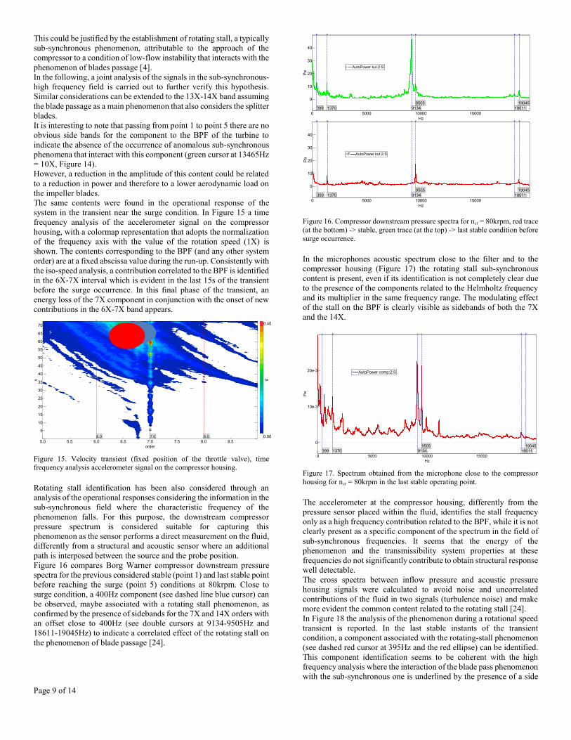
Figure 16 compares Borg Warner compressor downstream pressure
spectra for the previous considered stable (point 1) and last stable point
before reaching the surge (point 5) conditions at 80krpm. Close to
surge condition, a 400Hz component (see dashed line blue cursor) can
be observed, maybe associated with a rotating stall phenomenon, as
confirmed by the presence of sidebands for the 7X and 14X orders with
an offset close to 400Hz (see double cursors at 9134-9505Hz and
18611-19045Hz) to indicate a correlated effect of the rotating stall on
the phenomenon of blade passage [24].
Figure 16. Compressor downstream pressure spectra for ncr = 80krpm, red trace
(at the bottom) -> stable, green trace (at the top) -> last stable condition before
surge occurrence.
In the microphones acoustic spectrum close to the filter and to the
compressor housing (Figure 17) the rotating stall sub-synchronous
content is present, even if its identification is not completely clear due
to the presence of the components related to the Helmholtz frequency
and its multiplier in the same frequency range. The modulating effect
of the stall on the BPF is clearly visible as sidebands of both the 7X
and the 14X.
Figure 17. Spectrum obtained from the microphone close to the compressor
housing for ncr = 80krpm in the last stable operating point.
The accelerometer at the compressor housing, differently from the
pressure sensor placed within the fluid, identifies the stall frequency
only as a high frequency contribution related to the BPF, while it is not
clearly present as a specific component of the spectrum in the field of
sub-synchronous frequencies. It seems that the energy of the
phenomenon and the transmissibility system properties at these
frequencies do not significantly contribute to obtain structural response
well detectable.
The cross spectra between inflow pressure and acoustic pressure
housing signals were calculated to avoid noise and uncorrelated
contributions of the fluid in two signals (turbulence noise) and make
more evident the common content related to the rotating stall [24].
In Figure 18 the analysis of the phenomenon during a rotational speed
transient is reported. In the last stable instants of the transient
condition, a component associated with the rotating-stall phenomenon
(see dashed red cursor at 395Hz and the red ellipse) can be identified.
This component identification seems to be coherent with the high
frequency analysis where the interaction of the blade pass phenomenon
with the sub-synchronous one is underlined by the presence of a side
5.0 6.0 7.0 8.05.5 6.5 7.5 8.5
order
Derived Order (t:1)
10
20
30
40
50
60
70
5
15
25
35
45
55
65
s
0.40
0.00
g
7.0 8.06.0
0 100005000 15000
Hz
kul:2:S (CH11)
0
10
20
30
40
Pa
9134
9505
18611
19045
399 1370
AutoPower kul:2:S
0 100005000 15000
Hz
kul:2:S (CH11)
0
10
20
30
40
Pa
9134
9505
18611
19045
399 1370
F AutoPower kul:2:S
0 100005000 15000
Hz
comp:2:S (CH7)
0
10e-3
20e-3
Pa
9134
9505
18611
19045
399 1370
AutoPower comp:2:S

Page 10 of 14
band of the BPF. In the spectra, low frequency contributions can be
also detected as identified in the previous analysis related to the
dynamic response of the circuit.
Figure 18. Cross power spectrum between pressure sensor signal in the fluid
vein and microphone close to the compressor housing: common contributions between the signals (not-related ones are excluded).
Energy level analysis of filtered signal
The analysis on the frequency contents of the operational response
signals made it possible to identify which components mostly change
their value near an incipient surge condition.
This information was used to filter the acquired signals in order to keep
mainly sensitive contents and then calculate their Root Mean Square
(RMS) values. This technique allows to obtain a filtered signal
characterized by an energetic level affected by the surge occurrence,
thus more suitable to identify compressor instabilities.
At first, 3-300Hz frequency range, where frequency contents in system
response become more significant near surge, were considered and
shown in Figure 19 with reference to the microphone signal measured
at the filter.
In Figure 19, a colour contour of RMS filtered value is shown, in the
steady flow compressor pressure ratio and total-to-total efficiency
map. By reducing the mass flow rate for a constant rotational speed,
the filtered signal energy content increases approaching surge
condition, with a maximum level reached in deep surge.
Figure 19. Colormap of RMS value in the frequency range of 3-300 Hz for the
acoustic pressure measured at the filter section (Borg Warner compressor).
In Figures 20 and 21, the colour contour of RMS value in sub-
synchronous range respectively referred to the accelerometer signal
located at the inlet feeding line and to the outlet pressure signal in the
specific high frequency band 6X-7X is represented. The sensitivity of
these quantities is adequate to identify the system approach to a
condition of incipient surge.
In the case of the accelerometer, it seems interesting to note that the
lower RMS values occur near the zone of maximum efficiency, where
the flow incidence angle for the impeller seems to be optimum to
improve compressor vibro-acoustic response.
Figure 20. Colormap of RMS value in the whole sub-synchronous frequency
range for the accelerometer signal at the inlet section (Borg Warner).
Figure 21. Colormap of RMS value in frequency band 6X-7X of the outlet pressure signal (Borg Warner).
In general, at low mass flow rate level when the slope of the
compressor characteristic curves becomes near to zero, RMS values
previously considered highlight an increase, approaching the unstable
condition, resulting a possible surge precursor for diagnostic purpose.
Figure 22 shows the RMS value trends for the microphone (at the filter
and compressor housing) and inflow pressure signals during the
transient test for a specific sub-synchronous band between 3Hz and the
300Hz. In all cases, an increasing tendency in the trend of the energy
of the spectrum during the transient and a high variation of slope in
correspondence with the achievement of surge can be observed. This
aspect further highlights the significant change of low-frequency sub-
synchronous contents from a stable operating condition to a condition
close to the surge with low mass flow rate levels.
Figure 22. Borg Warner compressor - Spectral energy in the range 3-300Hz – inlet filter section and compressor housing microphones, in flow pressure signal
100 1000 1000050 60 70 80 200 300 400 500600 800 2000 3000 4000 6000
Hz
10
20
30
40
50
60
70
5
15
25
35
45
55
65
s
3.00
0.01
Pa
2/H
z
395
50000 60000 70000 80000 9000055000 65000 75000 85000
rpm
t:1 (T1)
80
90
100
110
dB
Pa
91511
Frequency band 3-300Hz asp:1:SFrequency band 3-300Hz comp:2:SFrequency band 3-300Hz kul:2:S
Page 11 of 14
Near incipient surge condition, significant frequency contents close to
the BPF (7X) may be noted as previously observed in the high
frequency signal analysis and this may be related to an interaction
between two sources (blade pass and stall) of the system generating a
modulation phenomenon [24].
To better analyse this behaviour, signal has been filtered in a band
between 6X and 8X orders (where these contents appear most
significant) and then a frequency analysis has been computed on the
filtered signal Hilbert envelope. In this way, it is possible to perform a
demodulation of the blade pass content adopting a methodology
analogous to the one used for detecting gear defects (in the considered
case, the gear mesh frequency corresponds to BPF) [25, 26].
Figure 23 represents a plot of the signal Hilbert envelope frequency
analysis for some operational response signals of the system in a stable
point (maximum efficiency condition - dotted line) and in the last
stable point for ncr = 80krpm. This technique seems to identify, for all
the signals considered in the second point of operation, a modulating
effect on the BPF, which could be due to a rotating stall phenomenon
(peak at 402Hz).
As previously highlighted, a direct FFT analysis on the signal (and not
on the envelope of the high pass filtered signal) with the exception of
the fluid vein pressure signal, generally does not allow to correctly
identify the sub-synchronous content of the rotating stall. This is due
to the presence of other contributions that make the identification more
complex or due to dynamic aspects related to the nature of the sensor
or the transmissibility of the system.
Figure 23. FFT analysis of the envelope function in the case of microphone
signals (asp:1, comp:2), structural signals (c: 1: + X) and fluid vein pressure (kul:1) - (Dotted line -> stable condition; continuous line -> last stable operating
point.
This method for rotary stall identification applied to the fluid vein
pressure sensor signal has been extended to both compressors. In Table
3 the obtained results and the evaluated rotating stall frequency (frs) are
reported. In some operating conditions (especially for low rotational
speed levels), the identification of the phenomenon frequency was not
possible, as for IHI turbocharger when the inlet section was
characterized by controlled pressure level and not by the ambient. This
layout configuration may be considered a more complex, and hence
the application method is less reliable.
Table 3. Rotating stall frequency (obtained from fluid vein pressure sensor
signal – last stable operational point) – (1) not identifiable from the experimental data; (2) controlled compressor inlet pressure; (3) from demodulation method
Turbocharger ncr
[krpm]
frs
[Hz]
1X
[Hz]
frs
[1X]
frs [Hz]
(3)
Borg Warner 50 (1) 845 (1) (1)
Borg Warner 65 199 1097 0.19 186
Borg Warner 80 399 1370 0.31 402
Borg Warner 95 450 1591 0.26 465
Borg Warner 110 432 1881 0.22 367
IHI (2) 59 (1) 993 (1) (1)
IHI (2) 89 (1) 1497 (1) (1)
IHI (2) 118 386 1986 0.19 389
IHI (2) 162 506 2743 0.19 464
IHI 89 383 1502 0.25 293
IHI 118 389 1992 0.19 408
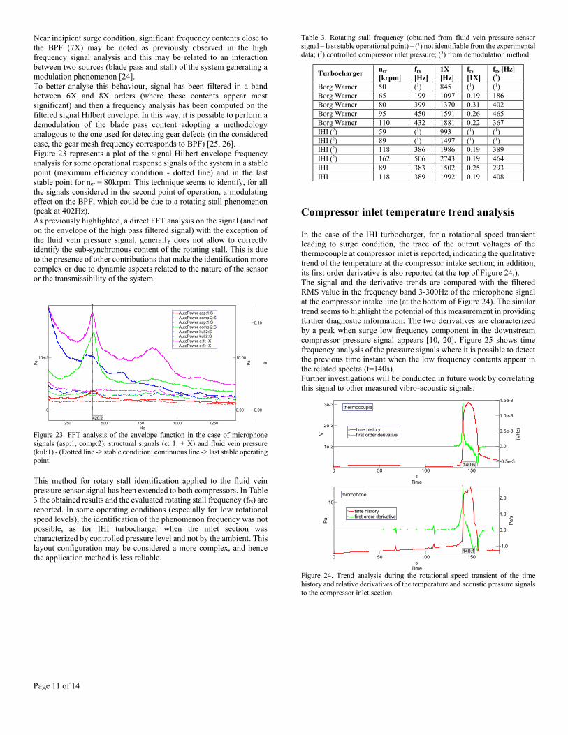
Compressor inlet temperature trend analysis
In the case of the IHI turbocharger, for a rotational speed transient
leading to surge condition, the trace of the output voltages of the
thermocouple at compressor inlet is reported, indicating the qualitative
trend of the temperature at the compressor intake section; in addition,
its first order derivative is also reported (at the top of Figure 24,).
The signal and the derivative trends are compared with the filtered
RMS value in the frequency band 3-300Hz of the microphone signal
at the compressor intake line (at the bottom of Figure 24). The similar
trend seems to highlight the potential of this measurement in providing
further diagnostic information. The two derivatives are characterized
by a peak when surge low frequency component in the downstream
compressor pressure signal appears [10, 20]. Figure 25 shows time
frequency analysis of the pressure signals where it is possible to detect
the previous time instant when the low frequency contents appear in
the related spectra (t=140s).
Further investigations will be conducted in future work by correlating
this signal to other measured vibro-acoustic signals.
Figure 24. Trend analysis during the rotational speed transient of the time history and relative derivatives of the temperature and acoustic pressure signals
to the compressor inlet section
1000500250 750 1250
Hz
0
10e-3
Pa
0.00
10.00
Pa
0.00
0.10
g
420.2
AutoPower asp:1:SAutoPower comp:2:SAutoPower asp:1:SAutoPower comp:2:SAutoPower kul:2:SAutoPower kul:2:SAutoPower c:1:+XAutoPower c:1:+X
0 50 100 150
s
Time
10
Pa
-1.0
0.0
1.0
2.0
Pa
/s
140.1
time historyfirst order derivative
microphone
0 50 100 150
s
Time
1e-3
2e-3
3e-3
V
-0.5e-3
0.0
0.5e-3
1.0e-3
1.5e-3
(VH
z)
140.6
time historyfirst order derivative
thermocouple

Page 12 of 14
Figure 25. Time frequency analysis during the transient of the downstream
compressor pressure – low frequency content detail (0-100Hz)
Rotational speed signal analysis
In this section, the rotational speed signal was analyzed to assess if
variations in frequency content are detectable during transition from a
stable to the unstable operating condition. The measurement system
returns a square wave whose period corresponds to a whole rotation or
part linked to the distribution of the blades on the impeller according
to the adopted settings. During the activity, the measurement device
provides two cycles in the output signal for a complete impeller
rotation.
The FFT analysis of the rotational speed signal shows a frequency
content consisting in a fundamental frequency (two pulses per
revolution) and only higher multiples in the case of stable compressor
condition (Figure 26, red trace). When the unstable condition is
approached, sidebands are detectable at the fundamental frequency of
the signal correlated to signal frequency modulation phenomena [24].
This could be due to an irregularity of the impeller motion correlated
to an incipient surge condition (see green and blue traces in the spectra,
Figure 26). In the presence of deep surge, the modulating phenomena
in the rotational speed signal are predominant, and their frequencies
are correlated to those identifiable in other system responses (low
frequency contents related to the dynamic response of the circuit).
The modulating phenomena take place at relatively low frequencies
(<10Hz) to exclude the presence of significant phenomena related to
torsional vibration due to the shaft line turbocharger structural
characteristics.
Figure 26. Frequency analysis of the rotational speed signal (at the top) and
rotational velocity time history (at the bottom) during surge transient - Borg
Warner turbocharger
Conclusions
In the paper, the main results of an experimental investigation on two
different turbocharger centrifugal compressors in stable and unstable
operating conditions are shown, with special reference to the transition
from a stable condition to the low flow instability region.
The aim of this study is to evaluate whether it is possible to predict the
incipient surge condition using suitable quantifier calculated from
instantaneous signals. Vibrational, acoustic and inflow pressure
system responses have been considered and their aptitude in detecting
the presence of specific operational sources has been preliminary
analyzed.
The spectrum energy level seems to be a useful quantifier for surge
prediction due to sub-synchronous and higher frequencies signal
contents.
For both compressors, incipient surge conditions are characterized by
a low frequency content close to the Helmholtz frequency of the
system and its multipliers. The system behavior seems strictly related
to the dynamic response of the circuit and slightly to the compressor
features and its operating conditions.
For the investigated components at frequencies up to 300 Hz, this
contribution seems to be well captured by microphone positioned at
the filter, differently from structural signals. This may be justified by
system transmissibility characteristics suitable to reduce the energy of
this specific low frequency content.
The deep surge condition can be easily recognized, since it is always
accompanied by high vibration levels and discernible noise. Both the
incipient surge and the deep surge seem to be characterized by similar
spectra contents.
In the downstream compressor pressure signal, a sub-synchronous
narrow band content is often present near unstable operating condition
may be related to a rotating stall. The detection of this phenomenon is
useful for diagnostic purpose as rotating stall often occur just before
the surge onset.
This specific content is difficult to be identified in acoustic and
structural system responses with sub-synchronous frequency band
0 10 20 30 40 50 60 70 80 905 15 25 35 45 55 65 75 85 95
Hz
0
100
50
s
6171.5
0.7
Pa
3.0 ; 1421.7
7.0 ; 4279.0
6.9 27.0 46.9 72.9
140.0
141.0
2600 2700 2800 2900 3000 3100 32002650 2750 2850 2950 3050 3150 3250
Hz
t:1 (CH10)
0.0
1.0
0.5
V
2693 3063
3047 3078
3143
3129
3156
3115
3169
2887
Spectrum t:1 80804 rpmSpectrum t:1 86704 rpmSpectrum t:1 91936 rpmSpectrum t:1 94279 rpm
60 7052 54 56 58 62 64 66 68 72 74 76
s
80000
90000
85000
95000
rpm
80804
94279
86704
91936

Page 13 of 14
analysis due to the presence of other contributions related to
resonances.
The rotating stall identification seems to be possible by detecting the
rise of its interaction with the high frequency blade passage
phenomenon. To this aim, a demodulation technique has been used by
means of a procedure based on the envelope analysis applied on band-
pass filtered acquired signal. In the envelope spectrum, the rotating
stall onset is well detectable since a specific sub-synchronous
frequency contents appears near low mass flow rate operating
conditions.
Through this method, the rotating stall diagnostic information may be
obtained not only starting from pressure signal, but also considering
the sub-synchronous frequency content of micro mono axial
accelerometers on compressor housing and microphones positioned
near the turbocharger.
Additional diagnostic information has been found from inlet section
thermocouple time-averaged signal trend analysis and by detecting the
presence of rotational speed irregularities near unstable low mass flow
rate conditions.
In future works, additional signal processing techniques (i.e., high
order spectral analysis [27], independent component analysis [28] and
blind sources separation [29]) will be considered to extract diagnostic
contents from the system response signals in order to define other
precursors and obtain a more reliable detection of incipient surge
condition. This diagnostic analysis will be considered [30, 31] to
develop an advanced control system able to prevent surge conditions
based on such precursors.
References
[1] Emmons, H.W., Pearson, C.E., and Grant, H.P., Compressor Surge
and Stall Propagation, Transactions of the ASME 77:455-469, 1955
[2] Fink, D.A., Cumpsty, N.A., and Greitzer, E.M., Surge Dynamics
in a Free-Spool Centrifugal Compressor System, J. Turbomachinery
114:321-332, 1992
[3] Yano, T. and Nagata, B., A Study on Surging Phenomena in Diesel
Engine Air-Charging System, The Japan Society of Mechanical
Engineers 14:364-376, 1971
[4] Greitzer, E.M., Surge and Rotating Stall in Axial Flow
Compressors. Part I: Theoretical Compression System Model. Journal
of Engineering for Power, 98 (1976) 190-198
[5] Biliotti, D., Bianchini, A., Vannini, G., Belardini, E., Giachi, M.,
Tapinassi, L., Ferrari, L., Ferrara, G., Analysis of the rotor dynamic
response of a centrifugal compressor Subject to aerodynamic loads due
to Rotating Stall, Journal of Turbomachinery ASME 2015, Vol. 137
[6] Bently, D. E., Goldman, P., Vibrational Diagnostics of Rotating
Stall in Centrifugal Compressors, ORBIT First Quarter 2000
[7] Munari, E., Morini, M., Pinelli, M., Spina, P.R., Suman, A.,
Experimental Investigation of Stall and Surge in a Multistage
Compressor, ASME Paper GT2016-57168, ASME Turbo Expo 2016,
Seoul, South Korea
[8] Liskiewicz G., Horodko, L., Stickland, M., Kryłłowicz, W.,
Identification of phenomena preceding blower surge by means of
pressure spectral maps. Experimental Thermal and Fluid Science, 54
(April 2014) Pages 267-278
[9] Kabral, R., Åbom, M. Investigation of turbocharger compressor
surge inception by means of an acoustic two-port model. Journal of
Sound and Vibration 412 (2018) 270e286
[10] Marelli, S., Misley, A., Taylor, A., Silviestri, P., Capobianco, M.,
Canova, M., Experimental Investigation on Surge Phenomena in an
Automotive Turbocharger Compressor. SAE Technical Papers, doi:
10.4271/2018-01-0976
[11] Ferrari, M.L., Silvestri, P., Pascenti, M., Reggio, F., Massardo,
A.F. Experimental Dynamic Analysis on a T100 Microturbine
Connected With Different Volume Sizes, ASME Transactions -
Journal of Engineering for Gas Turbines and Power, 140, 021701-1-
12, 2018
[12] Ferrari, M.L., Silvestri, P., Reggio, F., Massardo, A.F., Surge
prevention for gas turbines connected with large volume size:
Experimental demonstration with a microturbine, (2018) Applied
Energy, 230, pp. 1057-1064
[13] Dehner, R., Figurella, N., Selamet, A., Keller, P., Becker, M.,
Tallio, K., Miazgowicz, K., Wade, R., Instabilities at the low-flow
range of a turbocharger compressor, SAE Int. J. Engines 6 (2) (2013)
1356e1367, https://doi.org/10.4271/2013-01-1886
[14] Zhenzhong, S., Wangzhi, Z., Xinqian, Z., Instability detection of
centrifugal compressors by means of acoustic measurements,
Aerospace Scienceand Technology 82–83 (2018) 628–635
[15] Aretakis, N., Mathioudakis, K., Kefalakis, M., Papailiou, K.,
“Turbocharger unstable operation diagnosis using vibroacoustic
measurements, ASME Journal of Engineering for Gas Turbines and
Power,126 (Nov. 2004) pages 840-847
[16] Morini, M., Pinelli, M., Venturini, M., Acoustic and Vibrational
Analyses on a Multi-Stage Compressor for Unstable Behavior
Precursor Identification, ASME Paper GT2007-27040, ASME Turbo
Expo 2007, Montreal, Canada
[17] Munari, E., D’Elia, G., Morini, M., Mucchi, E., Pinelli, M., Spina,
P.R., “Experimental Investigation of Vibrational and Acoustic
Phenomena for Detecting the Stall and Surge of a Multistage
Compressor, ASME Journal of Engineering for Gas Turbines and
Power. 2018; 140(9):092605-092605-9. GTP-17-1451 doi:
10.1115/1.4038765
[18] Guillou, E., Gancedo, M., Gutmark, E., Experimental
Investigation of Flow Instability in a Turbocharger Ported Shroud
Compressor, Journal of Turbomachinery 2016, Vol. 138/061002-1
[19] Tanda, G., Marelli, S., Marmorato, G., Capobianco, M., An
experimental investigation of internal heat transfer in an automotive
turbocharger compressor, Applied Energy, 193, 531-539,
http://dx.doi.org/10.1016/j.apenergy.2017.02.053, 2017
[20] Marelli, S., Capobianco, M., Experimental investigation under
unsteady flow conditions on turbocharger compressors for automotive
gasoline engines, 10th International Conference on Turbochargers and
Turbocharging, Institution of Mechanical Engineers, pp. 219–229,
2012
[21] Marelli, S., Capobianco, M., Measurement of Instantaneous Fluid
Dynamic Parameters in Automotive Turbocharging Circuit, SAE
Technical paper 2009-24-0124, Proceedings of the 9th International
Conference on Engines for Automobile, doi: 10.4271/2009-24-0124,
2009
[22] Friswell, M. I., Penny, J. E. T., Garvey, S. D., Lees, A. W.,
Dynamics of Rotating Machines
[23] Muszyńska, A., Rotordynamics, CRC Press, Taylor & Francis
Group, ISBN 978-0-8247-2399-6, 2005
[24] Oppenheim, A.V., Schafer, R.W., Discrete-time signal
processing, Prentice-Hall, Inc. Upper Saddle River, NJ, USA, 1999.
[25] Randall, R.B. A new method of modelling gear faults, Journal of
Mechanical Design 104, 259-267, 1982
[26] Mcfadden, P.D. Detecting fatigue cracks in gear by amplitude and
phase demodulation of the meshing vibration, ASME J.of Vibration,
Acoustics, Stress, and Reliability in Design 108, 165-170
[27] Lotfi, S., Jaouher, B. A., Farhat, F., Application of higher order
spectral features and support vector machines forbearing faults
classification, ISA Transactions 54 (2015) 193–206
[28] Hyvärinen, A., Karhunen, J., Oja, E., Independent component
analysis, John Wiley & Sons, Inc
[29] Comon, P., Jutten, C., Handbook of Blind Source Separation
Independent Component Analysis and Applications, Elsevier Ltd
[30] Lucifredi, A., Silvestri, P. An overview of fundamental
requirements for a condition monitoring and fault diagnosis system for
machinery and power plants (2003) Proceedings of the Tenth
International Congress on Sound and Vibration, pp. 4691-4698

Page 14 of 14
[31] Aonzo, E., Lucifredi, A., Silvestri, P. Diagnostic modules based
on chaos theory for condition monitoring of rotating machinery, (2000)
Proceedings of the 25th International Conference on Noise and
Vibration Engineering, ISMA, pp. 937-944
Contact Information
Silvia Marelli (Associate Professor)
DIME, University of Genoa, Genoa, Italy
E-mail: [email protected]
Paolo Silvestri (Assistant Professor)
DIME, University of Genoa, Genoa, Italy
E-mail: [email protected]
Acknowledgments
The work presented in this paper was in part conducted with support
from The H2020 UPGRADE (High efficient Particulate free Gasoline
Engines) Project (Grant Agreement Number: 724036).