Incipient plasticity in 4H-SiC during quasistatic nanoindentation · 2019-05-22 · Incipient...
8
www.elsevier.com/locate/jmbbm Available online at www.sciencedirect.com Research Paper Incipient plasticity in 4H-SiC during quasistatic nanoindentation $ Saurav Goel a,b,n , Jiwang Yan b , Xichun Luo c , Anupam Agrawal d a School of Mechanical and Aerospace Engineering, Queen's University, Belfast BT95AH, UK b Department of Mechanical Engineering, Keio University, Yokohama 223-8522, Japan c Department of Design, Manufacture and Engineering Management, University of Strathclyde, Glasgow G11XQ, UK d Department of Business Administration, University of Illinois at Urbana Champaign, 61820, USA article info Article history: Received 11 September 2013 Received in revised form 2 December 2013 Accepted 4 December 2013 Available online 12 December 2013 Keywords: SiC Nanoindentation Plasticity Elastic response abstract Silicon carbide (SiC) is an important orthopedic material due to its inert nature and superior mechanical and tribological properties. Some of the potential applications of silicon carbide include coating for stents to enhance hemocompatibility, coating for prosthetic-bearing surfaces and uncemented joint prosthetics. This study is the first to explore nanomechanical response of single crystal 4H-SiC through quasistatic nanoindentation. Displacement controlled quasistatic nanoindentation experiments were performed on a single crystal 4H-SiC specimen using a blunt Berkovich indenter (300 nm tip radius) at extremely fine indentation depths of 5 nm, 10 nm, 12 nm, 25 nm, 30 nm and 50 nm. Load–displacement curve obtained from the indenta- tion experiments showed yielding or incipient plasticity in 4H-SiC typically at a shear stress of about 21 GPa ( an indentation depth of 33.8 nm) through a pop-in event. An interesting observation was that the residual depth of indent showed three distinct patterns: (i) positive depth hysteresis above 33 nm, (ii) no depth hysteresis at 12 nm, and (iii) negative depth hysteresis below 12 nm. This contrasting depth hysteresis phenomenon is hypothesized to originate due to the existence of compressive residual stresses (upto 143 MPa) induced in the specimen by the polishing process prior to the nanoindentation. Crown Copyright & 2013 Published by Elsevier Ltd. All rights reserved. 1. Introduction Silicon carbide (SiC) is an extremely hard and brittle non-oxide ceramic material. It has been demonstrated that, due to its superior properties, such as chemical inertness, high thermal conductivity, high carrier saturation velocity, high specific stiff- ness (E/ρ) and high-temperature resistance, SiC is an appropriate choice to replace silicon for advanced ultra precision engineering applications especially in the electronic industry (Neudeck and Technology, 2000). SiC is also recognized as a potential candidate for quantum computing applications as a substitute for diamond (Dzurak, 2011), in space-based laser mirrors (Shore et al., 2010) and for the development of the thermal protection system (TPS) materials for defense applications (Newsome et al., 2012). Demand of SiC is growing further in weapons, aerospace, microelectronic and bio-medical applications as well as in 1751-6161/$ - see front matter Crown Copyright & 2013 Published by Elsevier Ltd. All rights reserved. http://dx.doi.org/10.1016/j.jmbbm.2013.12.005 ☆ This paper was presented at the Fifth International Conference on the Mechanics of Biomaterials and Tissues (ICMOBT5). n Corresponding author at: School of Mechanical and Aerospace Engineering, Queen's University, Belfast BT95AH, UK. Tel.: þ44 028 9097 5625; fax: þ44 028 9097 4148. E-mail addresses: [email protected], [email protected] (S. Goel). journal of the mechanical behavior of biomedical materials34 (2014) 330–337
Transcript of Incipient plasticity in 4H-SiC during quasistatic nanoindentation · 2019-05-22 · Incipient...
Available online at www.sciencedirect.com
www.elsevier.com/locate/jmbbm
j o u r n a l o f t h e m e c h a n i c a l b e h a v i o r o f b i o m e d i c a l m a t e r i a l s 3 4 ( 2 0 1 4 ) 3 3 0 – 3 3 7
1751-6161/$ - see frohttp://dx.doi.org/10.
☆This paper wasnCorresponding a
Tel.: þ44 028 9097 56E-mail addresses:
Research Paper
Incipient plasticity in 4H-SiC duringquasistatic nanoindentation$
Saurav Goela,b,n, Jiwang Yanb, Xichun Luoc, Anupam Agrawald
aSchool of Mechanical and Aerospace Engineering, Queen's University, Belfast BT95AH, UKbDepartment of Mechanical Engineering, Keio University, Yokohama 223-8522, JapancDepartment of Design, Manufacture and Engineering Management, University of Strathclyde, Glasgow G11XQ, UKdDepartment of Business Administration, University of Illinois at Urbana Champaign, 61820, USA
a r t i c l e i n f o
Article history:
Received 11 September 2013
Received in revised form
2 December 2013
Accepted 4 December 2013
Available online 12 December 2013
Keywords:
SiC
Nanoindentation
Plasticity
Elastic response
nt matter Crown Copyri1016/j.jmbbm.2013.12.005
presented at the Fifth Inuthor at: School of Mech25; fax: þ44 028 9097 [email protected], sgoel.
a b s t r a c t
Silicon carbide (SiC) is an important orthopedic material due to its inert nature and superior
mechanical and tribological properties. Some of the potential applications of silicon carbide
include coating for stents to enhance hemocompatibility, coating for prosthetic-bearing surfaces
and uncemented joint prosthetics. This study is the first to explore nanomechanical response of
single crystal 4H-SiC through quasistatic nanoindentation. Displacement controlled quasistatic
nanoindentation experiments were performed on a single crystal 4H-SiC specimen using
a blunt Berkovich indenter (300 nm tip radius) at extremely fine indentation depths of 5 nm,
10 nm, 12 nm, 25 nm, 30 nm and 50 nm. Load–displacement curve obtained from the indenta-
tion experiments showed yielding or incipient plasticity in 4H-SiC typically at a shear stress of
about 21 GPa (�an indentation depth of 33.8 nm) through a pop-in event. An interesting
observation was that the residual depth of indent showed three distinct patterns: (i) positive
depth hysteresis above 33 nm, (ii) no depth hysteresis at 12 nm, and (iii) negative depth
hysteresis below 12 nm. This contrasting depth hysteresis phenomenon is hypothesized to
originate due to the existence of compressive residual stresses (upto 143MPa) induced in the
specimen by the polishing process prior to the nanoindentation.
Crown Copyright & 2013 Published by Elsevier Ltd. All rights reserved.
ght & 2013 Published by Elsevier Ltd. All rights reserved.
ternational Conference on the Mechanics of Biomaterials and Tissues (ICMOBT5).anical and Aerospace Engineering, Queen's University, Belfast BT95AH, [email protected] (S. Goel).
1. Introduction
Silicon carbide (SiC) is an extremely hard and brittle non-oxideceramic material. It has been demonstrated that, due to itssuperior properties, such as chemical inertness, high thermalconductivity, high carrier saturation velocity, high specific stiff-ness (E/ρ) and high-temperature resistance, SiC is an appropriatechoice to replace silicon for advanced ultra precision engineering
applications especially in the electronic industry (Neudeck andTechnology, 2000). SiC is also recognized as a potential candidatefor quantum computing applications as a substitute for diamond(Dzurak, 2011), in space-based laser mirrors (Shore et al., 2010)and for the development of the thermal protection system (TPS)materials for defense applications (Newsome et al., 2012).Demand of SiC is growing further in weapons, aerospace,microelectronic and bio-medical applications as well as in
YANJ
テキストボックス
Downloaded from Yan Laboratory, Keio University at http://www.yan.mech.keio.ac.jp. Redistribution is subject to copyright licence from the journal publisher.

j o u r n a l o f t h e m e c h a n i c a l b e h a v i o r o f b i o m e d i c a l m a t e r i a l s 3 4 ( 2 0 1 4 ) 3 3 0 – 3 3 7 331
“big-science” programmes such as the European Extremely LargeTelescope (E-ELT), the Atacama Large Millimeter/submillimeterArray (ALMA) and next generation extreme ultraviolet (EUV)lithography steppers.
SiC is also finding amazing applications in bio-medical sectorespecially as being a semi-conductor material because of beingmore bio-compatible over silicon (Coletti et al., 2007). Traditionalorthopedic materials such as cobalt chrome (CoCr), stainlesssteel and titanium on account of being low wear and oxidationresistant, succumb to bone loss which causes implant looseningresulting in a reactive implant surface while SiC is capable ofpermanently integrating into the new bone growth on account oflow wear debris and metallosis and is thus very effective ascoating for stents to enhance hemocompatibility and as a coat-ing for prosthetic-bearing surfaces and uncemented joint pros-thetics (Li et al., 2005). Nanocrystalline silicon carbide (SiC) istherefore known to carry the potential to become an importantand an interface biomaterial which will connect the threedisparate disciplines of electronics, material science and biologi-cal world (Coletti et al., 2006). Field results of Kalnins et al. (2002)applied directly on various patients provide further support forthe above arguments: they found that amorphous silicon carbidestents are more effective than stainless steel in reducing theearly and late coronary events.
Mechanical processing of SiC in particular is a dauntingtask at the moment owing primarily to the following uniquecharacteristics of SiC (Inasaki, 1987; Komanduri, 1996):
1.
SiC exhibits low thermal coefficient and high thermal con-ductivity. This is because of the higher proportion of covalentbonding compared to ionic bonding in SiC (9:1) with thenature of bonding dependent on the Goldschmidt number.The higher proportion of covalent bonding in SiC makes itrelatively insensitive to elevated temperature deformationand thus SiC cannot easily be deformed even at elevatedtemperatures.2.
The ratio of Young's modulus and Vickers hardness in SiCis only about 20 which signify that SiC is highly brittle.This is in contrast to soft ductile materials where this ratiocould be as high as 250.3.
The ratio of tensile strength to shear strength in SiC isextremely low (�1.5) in contrast to soft ductile metals wherethis ratio is as high as 10, making them easier to deformthrough plastic deformation rather than brittle fracture.4.
Low density and low mobility of dislocations leads to highhardness in SiC, while low surface energy due to smalldensity of electrons and high Young's modulus are thereasons of extreme brittleness in SiC. Owing to low surfaceenergy and high Young's modulus, SiC exhibits low fracturetoughness and thus poor machinability.5.
To induce the plastic deformation in a ceramic material suchas SiC, it requires five independent slip systems to meet thevon Mises criterion otherwise twinning or fracture prevails.Furthermore, SiC exhibits one-dimensional polymorph-ism: all polytypes have the same tetrahedral arrangementof Si and C atoms but different stacking sequences. It is dueto this reason that almost 250 polytypes of silicon carbide(SiC) have been recognized to date (Perrone, 2007). Across all
other polytypes, two major polymorphs are α-SiC and β-SiCwith hexagonal and zinc-blende lattice structures, respec-tively. The main engineering properties of β-SiC (3C–SiC) andα-SiC (6H–SiC and 4H-SiC) have already been summarizedelsewhere (Luo et al., 2012).
In the past, experimental trials have been reported onpolycrystalline 3C–SiC (CVD-SiC) (Ravindra et al., 2013; Zhaoet al., 2011), single crystal 6H–SiC (Patten et al., 2005; Levitaset al., 2012; Goel et al., 2013), polycrystalline 6H–SiC (reactionbonded SiC) (Yan et al., 2009) and single crystal 4H-SiC(Shayan et al., 2009; Ravindra and J.A., 2007). These studieswere focused on exploring the ductile-regime machining ofSiC and have shown that single crystal 6H–SiC exhibits aductile to brittle transition (DBT) depth of only 70 nm (Pattenet al., 2007) whereas DBT depth in CVD 3C–SiC (polycrystal-line) was found to be 550 nm (Bhattacharya et al., 2006).Compared to these two types of SiC, single crystal 4H-SiCshowed a much higher DBT depth of up to 820 nm (Ravindraand J.A., 2007). Besides offering a larger DBT depth, 4H-SiCalso offers the best machined surface and sub-surface integ-rity (Luo et al., 2012) across all other major polytypes of SiCwhich means that it is possible to obtain higher manufactur-ing productivity for single crystal 4H-SiC. Hence, an investi-gation on the nanomechanical response of 4H-SiC isscientifically important at this point of time in order to aidcost effective manufacturing of 4H-SiC. State-of-the-art veri-table resolution instruments using in-situ and ex-situ imaging,quasistatic nanoindentation, acoustic emission detection,and high-temperature testing are providing newer insightsinto nanoscale mechanics of materials. Quasistatic nanoin-dentation in particular permits systematic examination toenable better understanding of deformation mechanisms,evaluation of mechanical properties, and aspects of plasticityof brittle materials such as SiC. Furthermore, the onset ofplastic deformation in a specimen can be studied from such atest merely by a careful assessment of the Load–displace-ment (P–h) profile. In particular, although pop-in event in theP–h curve may arise due to several reasons depending on thetype of specimen e.g. discrete strain accommodationmechanism in metals, formation of cracks in brittle materialsor formation of shear bands in metallic glasses (Schuh andLund, 2004), but the first pop-in event in this study wasobserved to be associated with the elastic-plastic transition,signifying plastic deformation of the material.
Fig. 1 shows schematically how brittle materials behavedifferently from ductile materials when they are indentedeither by a large tipped radii or a small tipped radii indenter.It shows that ductile materials show plastic deformation asthe dominant mode of deformation whereas the response ofbrittle materials is dependent on both the tip radii of theindenter and the magnitude of the load (force applied to theindenter). When brittle materials are indented with a sharptip, they show plastic deformation at sufficiently low inden-tation loads, beyond which median and lateral cracks appear(Chen et al., 2005; Ravindra, 2011). The qualitative identifica-tion of the elastic–plastic response of brittle materials duringtheir nanoindentation reveal that almost any material,including super-hard substances like diamond and SiC, canbe deformed plastically even at low temperatures (Niihara,1979) under the influence of large hydrostatic stresses. With

Fig. 1 – Differences in the response of ductile and brittle materials during nanoindentation (Venkatesh and Izman, 2007).
j o u r n a l o f t h e m e c h a n i c a l b e h a v i o r o f b i o m e d i c a l m a t e r i a l s 3 4 ( 2 0 1 4 ) 3 3 0 – 3 3 7332
smaller indentation depths, the size of the resulting criticalstress field is small enough to avoid cleavage initiated at thedefects but, with larger indentation depths, the larger criticalstress field allows for sufficient nuclei for crack propagation,which initiate from defects within the material. These factorsmotivated the current study, wherein quasistatic nanoinden-tation experiments were conducted on 4H-SiC to study theincipient plasticity from the force–displacement (P–h) curve.
2. Experimental details
The nanoindentation tests were performed on a TI 900 HysitronTriboIndenter which takes advantage of an acoustic and thermalenclosure that enables capturing precise and sensitive readings(Probe Selection Guide — Hysitron Triboindenter Manual andIncorporated, 2007). Also, its patented capacitive transducerprovides superior sensitivity and stability over other similarinstruments. The specimen used was a single crystal 4H-SiCwafer having crystal orientation (001), diameter 50mm andthickness 5mm which was supplied by PAM-Xiamen Power-way Advanced Material Co. Ltd., China.
The indentation experiments were performed with a three-sided pyramidal Berkovich probe. Of particular relevance in thisregard was the nature of the tip apex, which is never atomicallysharp and exhibits significant blunting, as measured and verifiedduring the experiments. The method used for the measurementof tip radius involves indenting the tool profile on the copperblock. The profile curvature of indentation is copied, fitted to acircle and radius of the circle can be found by simple mathema-tical analysis (Javvaji, 2008). The measurement revealed the tipradius to be about 300 nm. In the experimental context of thecurrent study, the blunting of the Berkovich tip turned out to be abenefit rather than an experimental difficulty. This is becausethe blunted geometry of the nanoindenter can often be approxi-mated as spherical (Faisal et al., 2011). With this approximationof the tip geometry, it becomes possible to predict the elasticresponse using the Hertzian law for mechanical contacts, basedon isotropic continuum elasticity. This law predicts a simplepower-law form for the elastic portion of the load–displacement
curve, Pph3/2, (Schuh, 2006) with a proportionality constant thatis fully specified by the radius of the blunted indenter tip and theelastic properties of the two contacting materials. The same isevident from the loading curves as shown later.
Based on the above description, a series of displacementcontrolled quasistatic nanoindentations were performed at dif-ferent indentation depths. The displacement control feedbacksystem was preferred over load controlled feedback system tolimit the total indentation depth so as to avoid specimen effect(Kruzic et al., 2009). The time allowed for reaching maximumdisplacement in all the cases was 10 s and the indenter wasretracted immediately after attaining the peak indentation depthin duration of 10 s. Each test was performed twice (both resultswere observed to be consistent and hence results for only one setof experiments are presented for brevity). The indents weremade following the “quick approach” method. The QuickApproach method moves the indenter tip towards the specimento sense the exact height of the specimen at a specific point. Thismove helps in updating the sample safety height with an exactvalue. Bypassing this step could result in either crashing of thetip into the specimen or would otherwise take several hours tocontact the surface. Thus, quick approachmethod not only helpsin ensuring the measurement accuracy at finer depths ofindentation, but also ensures that the tip is operated withinthe “sample safety zones” in that the indenter tip is consideredto be safe to avoid any sudden lateral impact load on it. Table 1shows the various indentation depths used for the experiments.Along with the indentation depth, the table also shows the peakindentation load recorded from the plots obtained from thedevice and the hysteresis observed in the plots (These arediscussed subsequently).
3. Results and discussions
3.1. Depth hysteresis during nanoindentation
The P–h plots for various depths of indentation performedof 4H-SiC are shown in Fig. 2. Fig. 2(a) and (b) shows the

Table 1 – Displacement controlled quasistatic nanoindentation experiments performed on 4H-SiC.
Experiment number Indenter displacement (h) (nm) Peak load (P) (μN) Hysteresis observed
1 5 103 Negative hysteresis2 10 275 Negative hysteresis3 12 300 Complete elastic response with no hysteresis4 25 825 Elastic response with positive hysteresis5 30 1265 Elastic response with positive hysteresis6 50 2425 ElasticþPlastic response
j o u r n a l o f t h e m e c h a n i c a l b e h a v i o r o f b i o m e d i c a l m a t e r i a l s 3 4 ( 2 0 1 4 ) 3 3 0 – 3 3 7 333
P–h plots for the indentation depths of 5 nm and 10 nmrespectively.
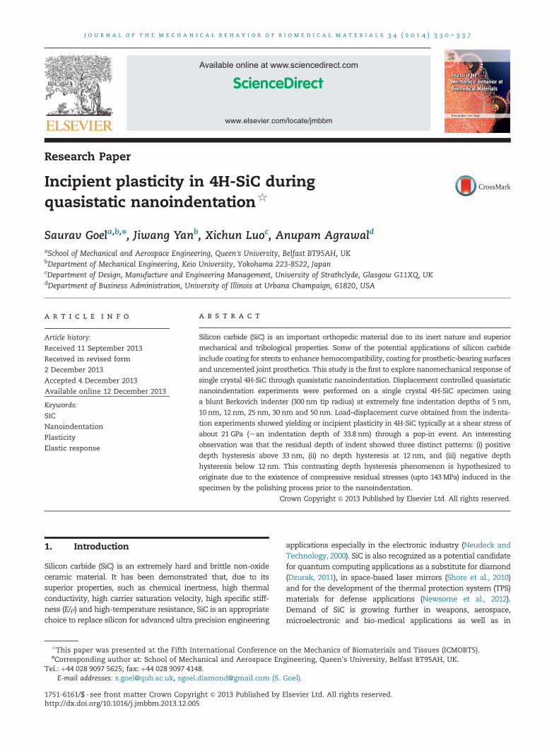
In both the cases (Fig. 2a and b), a negative depth hyster-esis of 12 mN and 20 mN respectively can be observed fromthese plots. Consequently, at these indentation depths, theOliver and Pharr method to evaluate the material propertiesfrom P–h curve cannot be used. Fig. 3 shows the AFM imagingand the cross section of the area in case where negativedepth hysteresis was observed.
In Fig. 3, it may be seen that at sufficiently lower depth ofindentation, the surface of the 4H-SiC specimen is projectingupwards (negative depth deviation) after the retraction of theindenter. This is somewhat unusual because extant researchon nanoindentation has reported that the unloading curvelags the loading curve and that is why the cross section of theindentation zone shows positive depth deviation. It was notimmediately clear as to why this negative depth hysteresiswas observed. One thing which may be noted here is that themanufacturer stated that the specimen of 4H-SiC supplied(used in this experimental study) was processed usingmechanical polishing process. The presence of residual stres-ses on the polished surface was thus expected to be present. Inorder to quantify such residual stresses, Raman spectroscopywas performed. Noticeably, against a regular Raman peak of776 cm�1 (Feldman et al., 1968) in 4H-SiC, the experimentsshowed the Raman peak at about 779.29 cm�1. This revealsthe extent of compressive residual stresses in the 4H-SiCspecimen to be about 143 MPa (compressive).
Based on this information, it is proposed that the negativedepth hysteresis in the unloading force could be due to theannealing and consequent thermal expansion of the surfacelayer of the specimen. This could happen due to the localheating (high heat at the interface of the indenter and thespecimen due to friction) of the surface layer which helps inrelieving the compressive residual stresses that are induced inthe specimen due to the polishing process carried out on thespecimen prior to the nanoindentation process. While compres-sive residual stresses get relieved due to annealing, the materialexpands which might have caused an opposite force on theindenter leading to this negative depth hysteresis. This phenom-enon implies and aligns with the concept of backward depthdeviation which appears in the form of hogging as has beenrecently observed in the thin films of Diamond like carbon (DLC)(Faisal et al., 2012) and SiC (Dharma Raju et al., 2003). Thisimplication is also supported from the AFM imaging shown inFig. 3 which confirms the presence of negative depth deviation.
Fig. 2(c) shows the P–h plot for the indentation made on 4H-SiC specimen at depth of 12 nm. Unlike the indents performed at
depths of 2 nm and 5 nm, no depth hysteresis was observed inthese plots. This implies that the material made a completeelastic recovery and unloading curve followed the same trendlike that of the loading curve. Fig. 2(d), (e) and (f) shows the P–hplots for the indentation made on 4H-SiC specimen at depths of25 nm, 30 nm and 50 nm respectively. In these figures, theindentation plot shows a different response of the specimeni.e. the ratio of hf/hmax is less than unity and at an indentationdepth of 50 nm a clear positive depth hysteresis is observed fromthese plots. As explained in the Section 3.2, this positivehysteresis is a result of the incipient plasticity in 4H-SiC. Thetypical response of the 4H-SiC specimen is schematically pre-sented in Fig. 4, highlighting the behavior of the specimen underdifferent depth of indentations as have been explained below.
3.2. Incipient plasticity in 4H-SiC
Recently, grain boundary (g.b) analysis in conjunction withLarge Angle Convergent Beam Electron Diffraction (LACBED)was used to propose that dislocations in 4H-SiC wereobserved to be in the basal plane with their Burgers vectoras 1/3⟨�1–120⟩ (Demenet et al., 2013). Also, perfect disloca-tions in 4H-SiC were proposed to dissociate into Shockleypartials as per the following reaction:
13⟨11�20⟩-
13⟨10�10⟩þ 1
3⟨01�10⟩ ð1Þ
For brittle materials like 4H-SiC, there may be two types ofdefect nucleations: dislocations or micro-cracks. The disloca-tions are induced by the onset plasticity, occurring when themaximum shear stress beneath the indenter exceeds thetheoretical shear strength of 4H-SiC. The Hertzian theorysuggests that the maximum tensile stress is at the edge of theindenter. This stress acts in a radial direction on the surfaceoutside the indenter, and is usually responsible for the conecracks (Buzio et al., 2003). When the tensile strength does notexceed the value of theoretical cleavage strength or when themaximum shear stress below the indenter tip approaches thetheoretical shear strength, then a pop-in event could occurdue to the incipient plasticity. Ostensibly, the pop-in event(kink showed in Fig. 2f) arises from the nanomechanicalresponse of the material, possibly due to an activity of defectnucleation or phase transformation underneath the indenter(Schuh, 2006; Chrobak et al., 2013). The parabolic shape of theP–h curve indicates elastic contact while displacement burstplus shallower slope is reminiscent of a combination ofelastic and plastic response. Beyond this point, the unloadingcurve follows the power law curve.

Fig. 2 – P–h plots for indentations made on single crystal 4H-SiC at various depths, (a) Indentation depth 5 nm, (b) Indentationdepth 10 nm, (c) Indentation depth 12 nm, (d) Indentation depth 25 nm, (e) Indentation depth 30 nm and (f) Indentation depth50 nm.
j o u r n a l o f t h e m e c h a n i c a l b e h a v i o r o f b i o m e d i c a l m a t e r i a l s 3 4 ( 2 0 1 4 ) 3 3 0 – 3 3 7334
An analytical stress analysis was carried out to find thestate of stress underneath the indenter in order to reveal theminutiae of the pop-in event. Before the pop-in event, the P–hcurve follows the Hertzian contact theory which could be
expressed using the following equation:
P¼ 43Er
ffiffiffiffiffiffiffiffiRh3
pð2Þ
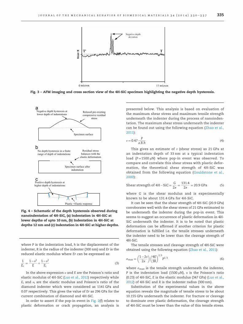
Fig. 4 – Schematic of the depth hysteresis observed duringnanoindentation of 4H-SiC, (a) Indentation in 4H-SiC atlower depths of upto 10 nm, (b) Indentation in 4H-SiC atdepths 12 nm and (c) Indentation in 4H-SiC at higher depths.
Negative depth deviation
Fig. 3 – AFM imaging and cross section view of the 4H-SiC specimen highlighting the negative depth hysteresis.
j o u r n a l o f t h e m e c h a n i c a l b e h a v i o r o f b i o m e d i c a l m a t e r i a l s 3 4 ( 2 0 1 4 ) 3 3 0 – 3 3 7 335
where P is the indentation load, h is the displacement of theindenter, R is the radius of the indenter (300 nm) and Er is thereduced elastic modulus where Er can be expressed as:
1Er
¼ 1�υ2
Eþ 1�υ2
Eið3Þ
In the above expression υ and E are the Poisson's ratio andelastic modulus of 4H-SiC (Luo et al., 2012) respectively whileEi and υi are the elastic modulus and Poisson's ratio of thediamond indenter which were considered as 1141 GPa and0.07 respectively. This gives the value of Er as 296 GPa for thecurrent combination of diamond and 4H-SiC.
In order to assert if the pop-in event in Fig. 2(f) relates toplastic deformation or crack propagation, an analysis is
presented below. This analysis is based on evaluation ofthe maximum shear stress and maximum tensile strengthunderneath the indenter during the process of nanoinden-tation. The maximum shear stress underneath the indentercan be found out using the following equation (Zhao et al.,2011):
τ¼ 0:47P
π:R:hð4Þ
This gives an estimate of τ (shear stress) as 21 GPa atan indentation depth of 33 nm at a typical indentationload (P¼1500 mN) where pop-in event was observed. Tocompare and correlate this shear stress with plastic defor-mation, the theoretical shear strength of 4H-SiC wasobtained from the following equation (Gouldstone et al.,2000):
Shear strength of 4H�SiC¼ G2π
¼ 131:42π
¼ 20:9 GPa ð5Þ
where G is the shear modulus and is experimentallyknown to be about 131.4 GPa for 4H-SiC.
It can be seen that the shear strength of 4H-SiC (20.9 GPa)corroborates well with the shear stress of 21 GPa estimated tobe underneath the indenter during the pop-in event. Thisseems to suggest an occurrence of plastic deformation in 4H-SiC underneath the indenter. It is to be noted that plasticdeformation can be affirmed if another criterion for plasticdeformation is fulfilled i.e. the tensile stresses underneaththe indenter need to be lower than the cleavage strength of4H-SiC.
The tensile stresses and cleavage strength of 4H-SiC wereobtained using the following equation (Zhao et al., 2011):
smax ¼ 1�2υ2π
� �4E3R
� �2=3
P1=3 ð6Þ
where smax is the tensile strength underneath the indenter,P is the indentation load (1500 mN), υ is the Poisson's ratio(0.23) of 4H-SiC, E is the elastic modulus (347 GPa) (Luo et al.,2012) of 4H-SiC and R is the indenter radius (300 nm).
Substitution of the experimental values in the aboveequation reveals the magnitude of tensile stress to be about10.155 GPa underneath the indenter. For fracture or cleavageto dominate over plastic deformation, the cleavage strengthof 4H-SiC must be lower than the value of this tensile stress.

Fig. 5 – Evolution of shear stress and tensile stressunderneath the Berkovich indenter (300 nm edge radius)during nanoindentation of nanocrystalline 4H-SiC atindentation depths up to 50 nm
j o u r n a l o f t h e m e c h a n i c a l b e h a v i o r o f b i o m e d i c a l m a t e r i a l s 3 4 ( 2 0 1 4 ) 3 3 0 – 3 3 7336
The following equation was used to calculate the cleavagestrength of 4H-SiC.
Cleavage strength of 4H�SiC¼ 12
ffiffiffiffiffiEγa
rð7Þ
where E is the elastic modulus of 4H-SiC (347 GPa), γ is surfacetension (6.5 J/m2 Otubo et al., 2013) and a is the interplanarspacing (3.079 Å) in 4H-SiC.
Substitution of the above values reveals the magnitude ofcleavage strength to be 13.53 GPa. Fig. 5 shows the evolutionof the tensile stress and shear stress underneath the indenter(the figure was drawn using Eqs. (2)–(6) and (7)) and highlightsthe theoretical shear strength and theoretical cleavagestrength of 4H-SiC.
It can be seen from Fig. 5 and from the above calculationsthat the theoretical shear strength calculation coincides withthe pop-in event observed at an indentation depth of 33 nmwhereas the tensile stresses at this point were far lower(10.155 GPa). This proves that the plastic deformation in 4H-SiC during the pop-in event leads to elastic-plastic transitionand thus explains that the observed incipient plasticity is dueto plastic deformation rather than the micro cleavage orfracture in 4H-SiC. The analysis presented above also revealsthat during contact loading of single crystal 4H-SiC, tensileand shear stresses underneath the indenter, increase with anincrease in the indentation depth. At shallow depths ofindentation (lower than 33 nm while using an indenter withthe edge radius of 300 nm), the induced shear stress is lowerthan the theoretical shear strength of the specimen andhence material showed pure elastic response. With anincrease in the extent of displacement, when the shear stressunderneath the indenter exceeds the theoretical shearstrength of 4H-SiC, a pop-in event is observed, which indi-cates induced plastic response. Such a plastic response is dueto the plastic deformation and not because of the crackpropagation because until this point, the theoretical cleavage
strength is much higher than the tensile stress underneaththe indenter.
4. Conclusions
Displacement controlled quasistatic nanoindentations onsingle crystal 4H-SiC were analyzed. Typically below a shearstress of 21 GPa, 4H-SiC showed purely elastic response whileplasticity was observed beyond this point. Based on theforegoing discussions, following other conclusions can bedrawn:
1.
Three distinct patterns in the P–h plots were observed duringnanoindentation of 4H-SiC (i) with negative depth hysteresis(ii) with no depth hysteresis and (iii) with positive depthhysteresis. This depth hysteresis is proposed to arise fromcompressive residual stresses (�143 MPa).2.
An analytical stress analysis was carried out to calculatethe theoretical shear strength and cleavage strength of 4H-SiC along with the shear stress and tensile stress under-neath the indenter. The theoretical shear strength wasestimated to be about 20.9 GPa which was found tocorroborate with the shear stress (21 GPa) underneaththe indenter whereas the theoretical cleavage strengthwas estimated to be 13.53 GPa which was noted to bemuch higher than the estimated tensile stress of10.155 GPa underneath the indenter. Comparison of thesevalues reveals that pop-in event occurred on account ofplastic deformation in 4H-SiC rather than fracture (thusindicating that the pop-in event is an outcome of theincipient plasticity in 4H-SiC).Acknowledgements
Authors greatly acknowledge the funding support from J MLessells travel scholarship from the Royal Society of Edin-burgh (2013 RSE/J M Lessells Travel Scholarship) and anadditional funding from the International Research Fellow-ship account of Queen's University, Belfast. Authors alsogreatly acknowledge an additional funding from an EPSRCresearch grant (Ref: EP/K018345/1).
r e f e r e n c e s
Bhattacharya, B., Patten, J.A., and Jacob, J., Single point diamondturning of CVD coated silicon carbide. ASME ConferenceProceedings, 2006. 2006(47624): p. 1153-1158.
Buzio, R., Boragno, C., Biscarini, F., De Mongeot, F.B., Valbusa, U.,2003. The contact mechanics of fractal surfaces. Nat. Mater. 2(4), 233–236.
Chen, X., Hutchinson, J.W., Evans, A.G., 2005. The mechanics ofindentation induced lateral cracking. J. Am. Ceram. Soc. 88 (5),1233–1238.
Coletti, C., Jaroszeski, M., Hoff, A.M., Saddow, S.E., 2006. Cultureof mammalian cells on single crystal SiC substrates. inMaterial Research Society Symposium Proceedings.Cambridge University Press.
Chrobak, D., Kwang-Ho, Kim., Kurzydłowski, K.J., Nowak, R., 2013.Nanoindentation experiments with different loading rate

j o u r n a l o f t h e m e c h a n i c a l b e h a v i o r o f b i o m e d i c a l m a t e r i a l s 3 4 ( 2 0 1 4 ) 3 3 0 – 3 3 7 337
distinguish the mechanism of incipient plasticity. Appl. Phys.Lett. 103, 072101. http://dx.doi.org/10.1063/1.4818260.
Coletti, C., Jaroszeski, M., Pallaoro, A., Hoff, A., Iannotta, S.,Saddow, S., 2007. Biocompatibility and wettability ofcrystalline SiC and Si surfaces. In: Proceedings of 29th AnnualInternational Conference of the IEEE, Engineering in Medicineand Biology Society. EMBS 2007.
Demenet, J.-L., Amer, M., Tromas, C., Eyidi, D., Rabier, J., 2013.Dislocations in 4H- and 3C–SiC single crystals in the brittleregime. Phys. Status Solidi C 10 (1), 64–67.
Dharma Raju, T., Kato, M., Nakasa, K., 2003. Backward deviationand depth recovery of load–displacement curves ofamorphous SiC film under repeating nanoindentation. ActaMater. 51 (12), 3585–3595.
Dzurak, A., 2011. Quantum computing: diamond and siliconconverge. Nature 479 (7371), 47–48.
Faisal, N., Ahmed, R., Reuben, R., 2011. Indentation testing and itsacoustic emission response: applications and emergingtrends. Int. Mater. Rev. 56 (2), 98–142.
Faisal, N.H., Ahmed, R., Fu, Y.Q., Elakwah, Y.O., Alhoshan, M.,2012. Influence of indenter shape on DLC film failure duringmultiple load cycle nanoindentation. Mater. Sci. Technol. 28(9–10), 1186–1197.
Feldman, D., Parker Jr., J.H., Choyke, W., Patrick, L., 1968. Phonondispersion curves by Raman scattering in SiC, polytypes 3C,4H, 6H, 15R, and 21R. Phys. Rev. 173 (3), 787.
Goel, S., Luo, X., Comley, P., Reuben, R.L., Cox, A., 2013. Brittle–ductile transition during diamond turning of single crystalsilicon carbide. Int. J. Mach. Tools Manuf. 65, 15–21.
Gouldstone, A., Koh, H.J., Zeng, K.Y., Giannakopoulos, A.E.,Suresh, S., 2000. Discrete and continuous deformation duringnanoindentation of thin films. Acta Mater. 48 (9), 2277–2295.
Inasaki, I., 1987. Grinding of hard and brittle materials. CIRPAnnal. – Manuf. Technol. 36 (2), 463–471.
Javvaji, R., 2008. Nanoscale Ductile Mode Ultraprecision Cuttingof Potassium Dihydrogen Phosphate in MechanicalEngineering. National University of Singapore, Singapore.
Kalnins, U., Erglis, A., Dinne, I., Kumsars, I., Jegere, S., 2002.Clinical outcomes of silicon carbide coated stents in patientswith coronary artery disease. Med. Sci. Monit.: Int. Med. J. Exp.Clin. Res. 8 (2), PI16–PI20.
Komanduri, R., 1996. On material removal mechanisms infinishing of advanced ceramics and glasses. CIRP Annal. —Manuf. Technol. 45 (1), 509–514.
Kruzic, J.J., Kim, D.K., Koester, K.J., Ritchie, R.O., 2009. Indentationtechniques for evaluating the fracture toughness ofbiomaterials and hard tissues. J. the Mech. Behav. .Biomed.Mater. 2 (4), 384–395.
Levitas, V.I., Ma, Y., Selvi, E., Wu, J., Patten, J.A., 2012. High-densityamorphous phase of silicon carbide obtained under largeplastic shear and high pressure. Phys. Rev. B 85 (5), 054114.
Li, X., Wang, X., Bondokov, R., Morris, J., An, Y.H., Sudarshan, T.S.,2005. Micro/nanoscale mechanical and tribologicalcharacterization of SiC for orthopedic applications. J. Biomed.Mater. Res. Part B: Appl. Biomater. 72B (2), 353–361.
Luo, X., Goel, S., Reuben, R.L., 2012. A quantitative assessment ofnanometric machinability of major polytypes of single crystalsilicon carbide. J. Eur. Ceram. Soc. 32 (12), 3423–3434.
Neudeck, P.G., Technology, SiC, 2000. In: Raton, B. (Ed.), The VLSIHandbook. CRC Press and IEEE Press, Florida, pp. 6.1–6.24.
Newsome, D.A., Sengupta, D., Foroutan, H., Russo, M.F., van Duin,A.C., 2012. Oxidation of silicon carbide by O2 and H2O: aReaxFF reactive molecular dynamics study, part I. J. Phys.Chem. C 116 (30), 16111–16121.
Niihara, K., 1979. Slip systems and plastic deformation of siliconcarbide single crystals at high temperatures. J. Less CommonMet. 65 (1), 155–166.
Otubo, H., Yamamoto, Y., Takekuni, H., Nishitani, S.R., 2013. FirstPrinciples Calculations of Relaxed and Reconstructed Surfacesof SiC. Accessed Through google.com on 26.8.2013.
Patten, J., Gao, W., Yasuto, K., 2005. Ductile regimenanomachining of single-crystal silicon carbide. J. Manuf. Sci.Eng. 127 (3), 522–532.
Patten, J.A., Jacob, J., Bhattacharya, B., Grevstad, Andrew, Fang,Ning, Marsh, E.R., 2007. Numerical simulations and cuttingexperiments on single point diamond machining ofsemiconductors and ceramics. In: Yan, J., Patten, J.A. (Eds.),Semiconductor Machining at the Micro-Nano Scale.Transworld Research Network, Trivandrum-695 023, Kerala,India (Chapter 2).
Probe Selection Guide — Hysitron Triboindenter Manual,Incorporated, H., Ed., 2007. Minneapolis, USA.
Perrone, D., 2007. Process and characterisation techniques on 4H-Silicon Carbide, in Micronanotechnology (Ph.D. thesis).Politecnico di Torino, Torino.
Ravindra, D., 2011. Ductile mode material removal of ceramics andsemiconductors, in Department of Mechanical and AeronauticalEngineering. Western Michigan University, Michigan312.
Ravindra, D., Patten, J.A., 2007. Determining the ductile to brittletransition (DBT) of a single-crystal 4H-SiC wafer byperforming nanometric cutting. In: Proceedings of ISAAT 2007Precision Grinding and Abrasive Technology at SMEInternational Grinding Conference.
Ravindra, D., Patten, J., Jacobsen, R., 2013. Hybrid laser ablation–single point diamond turning machining process for CVD–silicon carbide ceramics. Int. J. Manuf. Res. 8 (3), 227–249.
Schuh, C.A., 2006. Nanoindentation studies of materials. Mater.Today 9 (5), 32–40.
Schuh, C.A., Lund, A.C., 2004. Application of nucleation theory tothe rate dependence of incipient plasticity duringnanoindentation. J. Mater. Res. 19 (07), 2152–2158.
Shayan, A.R., Poyraz, H.B., Ravindra, D., Ghantasala, M., Patten, J.A., 2009. Force analysis, mechanical energy and laser heatingevaluation of scratch tests on silicon carbide (4H-SiC) inmicro-laser assisted machining ([micro sign]-LAM) process.ASME Conference Proc. 2009 (43611), 827–832.
Shore, P., Cunningham, C., DeBra, D., Evans, C., Hough, J.,Gilmozzi, R., Kunzmann, H., Morantz, P., Tonnellier, X., 2010.Precision engineering for astronomy and gravity science. CIRPAnnal. — Manuf. Technol. 59 (2), 694–716.
Venkatesh, V.C., Izman, Sudin, 2007. Precision Engineering. TataMacgraw Hill, New Delhi, India http://dx.doi.org/10.1036/0071548270.
Yan, J., Zhang, Z., Kuriyagawa, T., 2009. Mechanism for materialremoval in diamond turning of reaction-bonded siliconcarbide. Int. J. Mach. Tools Manuf. 49 (5), 366–374.
Zhao, X., Langford, R.M., Shapiro, I.P., Xiao, P., 2011. Onset plasticdeformation and cracking behavior of silicon carbide undercontact load at room temperature. J. Am. Cerami. Soc. 94 (10),3509–3514.