INCIDENT REVIEW – OTAHUHU SUBSTATION LOSS …img.scoop.co.nz/media/pdfs/0606/skmreport.pdfIncident...
30
INCIDENT REVIEW – OTAHUHU SUBSTATION LOSS OF SUPPLY 12 TH JUNE 2006 Interim Report 23 June 2006
Transcript of INCIDENT REVIEW – OTAHUHU SUBSTATION LOSS …img.scoop.co.nz/media/pdfs/0606/skmreport.pdfIncident...
INCIDENT REVIEW – OTAHUHU SUBSTATION LOSS OF SUPPLY 12TH JUNE 2006
Interim Report 23 June 2006

INCIDENT REVIEW – OTAHUHU SUBSTATION LOSS OF SUPPLY 12TH JUNE 2006
Interim Report 23 June 2006
Sinclair Knight Merz Level 12, Mayfair House 54 The Terrace PO Box 10-283 Wellington New Zealand Tel: +64 4 473 4265 Fax: +64 4 473 3369 Web: www.skmconsulting.com COPYRIGHT: The concepts and information contained in this document are the property of Sinclair Knight Merz Limited. Use or copying of this document in whole or in part without the written permission of Sinclair Knight Merz constitutes an infringement of copyright.
LIMITATION: This report has been prepared on behalf of and for the exclusive use of Sinclair Knight Merz Limited’s Client, and is subject to and issued in connection with the provisions of the agreement between Sinclair Knight Merz and its Client. Sinclair Knight Merz accepts no liability or responsibility whatsoever for or in respect of any use of or reliance upon this report by any third party.

Incident Review Otahuhu Substation 12th June 2006
SINCLAIR KNIGHT MERZ
I:\Apwr\Projects\AP01106\Deliverables\Instruction 19\Report 23062006-Interim.doc PAGE i
Contents
1. Executive Summary 1
2. Background to the Assignment 3
3. Approach to the Assignment 4
4. Information used in the Assignment 5 4.1 Weather conditions 5 4.2 OHEW tension 5 4.3 Observations and photographs 6 4.4 Protection information 6 4.5 Recovered hardware 6
5. Incident Review Findings 7 5.1 TI 19 2(a) - Identify what failed 8 5.1.1 The first failure 8 5.1.2 The second failure 8 5.1.3 OHEW condition 9 5.2 TI 19 2(b) - Identify the Maintenance Plan 9 5.3 TI 19 2(c) - Assess whether Transpower was following the Plan 9 5.4 TI 19 2(d) - Note any adjustments to the Maintenance Plan 10 5.4.1 Condition assessment 11 5.4.2 Accelerated corrosion 11 5.5 Substation Layout Design 11
Appendix A Transpower Instruction 13
Appendix B Technical terms 14
Appendix C Interviews conducted 15
Appendix D Transpower protection information 15
Appendix E Photographs and Drawings 15 E.1 Photographs 15 E.2 Drawings 15
Appendix F Substation Layout Design –File Note 15

Incident Review Otahuhu Substation 12th June 2006
SINCLAIR KNIGHT MERZ
I:\Apwr\Projects\AP01106\Deliverables\Instruction 19\Report 23062006-Interim.doc PAGE ii
Document history and status Revision Date issued Reviewed by Approved by Date approved Revision type
Interim 23 June 2006 F Lewis R McDougall 23 June 2006 Interim Report
Distribution of copies Revision Copy no Quantity Issued to
Interim Electronic copy 1 R Simpson Transpower
Printed: 23 June 2006
Last saved: 23 June 2006 08:12 AM
File name: I:\Apwr\Projects\AP01106\Deliverables\Instruction 19\Report 23062006-Interim.doc
Author: Doug Wells
Project manager: Frank Lewis
Name of organisation: Transpower
Name of project: Incident Review - 12th June 2006 Otahuhu Loss of Supply
Name of document: Incident Review Otahuhu Substation Loss of Supply 12th June 2006
Document version: Interim Report
Project number: AP01106.19

Incident Review Otahuhu Substation 12th June 2006
SINCLAIR KNIGHT MERZ
I:\Apwr\Projects\AP01106\Deliverables\Instruction 19\Report 23062006-Interim.doc PAGE 1
1. Executive Summary On the 13th June SKM was asked to undertake an incident report of the events that occurred at Otahuhu substation on 12th June 2006 leading to a significant loss of supply to the Auckland area.
The failures occurred on the overhead earthwires between the Otahuhu switchyard gantry and the terminal tower carrying the Otahuhu – Penrose 5 and Otahuhu – Otahuhu CCGT Tie Line 3 220kV circuits. The transmission line was commissioned in June 1966.
Transpower asked SKM to;
a) Identify what failed,
b) Identify the Maintenance Plan that covers items involved in the failure,
c) Assess whether Transpower was following the Plan,
d) Note any adjustments to the Maintenance Plan that might be needed as a result of this review, including for instance, assessment of how feasible it was for the planned processes to have identified the potential failure, and any changes.
The findings of this incident review are summarised below. The detailed findings are set out in Section 5 of this report.
Findings summary a) There were two component failures. In each case, the shackle forming part of the hardware
assembly attaching the overhead earthwire to the substation gantry failed. Both overhead earthwires were between the Otahuhu substation gantry and Tower 1 of the 220 kV double circuit transmission line carrying the Otahuhu – Penrose 5 and Otahuhu –Otahuhu CCGT Tie Line 3 220 kV circuits. Both shackles are in similar condition and show significant metal loss and corrosion.
The National Institute of Water and Atmospheric Research estimated that the wind gusts at the time of failure were approximately 90km/hr. The design wind speed was 140km/hr.
While the first failure was triggered by the high wind, the failure occurred because of the poor condition of the shackle.
The second failure occurred approximately five seconds after the first failure. There is evidence that fault current flowed through the second shackle. It is considered that the trigger for the second failure was the fault current or high wind or a combination of both. The cause of the failure was the poor condition of the shackle.
Incident Review Otahuhu Substation 12th June 2006
SINCLAIR KNIGHT MERZ
I:\Apwr\Projects\AP01106\Deliverables\Instruction 19\Report 23062006-Interim.doc PAGE 2
b) The Maintenance Plan that covers the items involved in the failures is set out in the Transpower service specification TP.SS 02.17 – “Transmission line condition assessment”, Issue 2, Jun 2003. It is considered that this document adequately covers the technical requirements for condition assessment.
c) It is considered that Transpower was following the Plan.
d) It is considered that the condition of the shackles should have been identified during the October 2003 condition assessment and replacement action instigated at that time. Contractor inspections recorded in the Transpower Maintenance Management System (MMS), by the Contractor, indicated that no equipment replacement was required. Therefore it is considered that no adjustments are required to the Maintenance Plan.
In making these findings it is noted that;
The transmission line and the spans connecting it to the gantry at Otahuhu Substation are 40 years old,
The design, construction and equipment of the transmission line generally reflect good practice, and
The transmission line crosses the four 110 kV bus sections to reach the 220 kV switchyard. Failure of any one component of the transmission line, overhead earthwire or phase conductor, can lead to the loss of not only the 220 kV circuit, but a number of 110 kV circuits supplying Auckland.
This layout is the result of the limited transmission line access into the Otahuhu Substation site and the design practices of the time (1960’s) when the substation layout was developed. Modern practice would be to avoid this situation, particularly in key substations on the network, by installing underground cable sections between transmission line terminal structure and the switchyard if necessary.

Incident Review Otahuhu Substation 12th June 2006
SINCLAIR KNIGHT MERZ
I:\Apwr\Projects\AP01106\Deliverables\Instruction 19\Report 23062006-Interim.doc PAGE 3
2. Background to the Assignment On Monday 12th June 2006 supply was lost at Otahuhu Substation, a major node on the Transpower 220 kV network and a key supply point for Auckland.
Otahuhu Substation has an installed transformer capacity of 800 MVA, gas turbine generating units with an installed capacity of 400 MW and supplies the Auckland area over several 220kV and 110 kV circuits.
On Tuesday 13th June 2006 Transpower requested SKM to;
a) Identify what failed,
b) Identify the Maintenance Plan that covers items involved in the failure,
c) Assess whether Transpower was following the Plan,
d) Note any adjustments to the Maintenance Plan that might needed as a result of this review, including for instance, assessment of how feasible it was for the planned processes to have identified the potential failure, and any changes.
The Transpower instruction for this investigation is found in Appendix A.
The technical terms used in this report are defined in Appendix B.
The failures occurred on the overhead earthwires (OHEWs) between Tower 1 carrying the Otahuhu – Penrose 5 and Otahuhu –Otahuhu CCGT Tie Line 3 220kV circuits and the gantry for the 512 and 522 switchyard bays. In this report the earthwires are referred to as OHEW 512 and OHEW 522.

Incident Review Otahuhu Substation 12th June 2006
SINCLAIR KNIGHT MERZ
I:\Apwr\Projects\AP01106\Deliverables\Instruction 19\Report 23062006-Interim.doc PAGE 4
3. Approach to the Assignment The following activities were undertaken to address the matters raised in the Transpower Instruction;
Interviews were held with Transpower staff and staff of the line maintenance Contractor responsible for condition assessment and maintenance of the 220 kV transmission line,
Review of Transpower and Contractor processes,
Review of Transpower maintenance documents,
Review of Maintenance Management System (MMS) data,
Review of maintenance Contractor field notes,
Site inspection, and
Technical assessment.
Incident Review Otahuhu Substation 12th June 2006
SINCLAIR KNIGHT MERZ
I:\Apwr\Projects\AP01106\Deliverables\Instruction 19\Report 23062006-Interim.doc PAGE 5
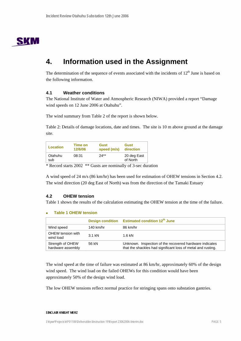
4. Information used in the Assignment The determination of the sequence of events associated with the incidents of 12th June is based on the following information.
4.1 Weather conditions The National Institute of Water and Atmospheric Research (NIWA) provided a report “Damage wind speeds on 12 June 2006 at Otahuhu”.
The wind summary from Table 2 of the report is shown below.
Table 2: Details of damage locations, date and times. The site is 10 m above ground at the damage site.
Location Time on 12/6/06
Gust speed (m/s)
Gust direction
Otahuhu sub
08:31 24** 20 deg East of North
* Record starts 2002 ** Gusts are nominally of 3-sec duration
A wind speed of 24 m/s (86 km/hr) has been used for estimation of OHEW tensions in Section 4.2. The wind direction (20 deg East of North) was from the direction of the Tamaki Estuary
4.2 OHEW tension Table 1 shows the results of the calculation estimating the OHEW tension at the time of the failure.
Table 1 OHEW tension
Design condition Estimated condition 12th June
Wind speed 140 km/hr 86 km/hr OHEW tension with wind load 3.1 kN 1.6 kN
Strength of OHEW hardware assembly
56 kN Unknown. Inspection of the recovered hardware indicates that the shackles had significant loss of metal and rusting.
The wind speed at the time of failure was estimated at 86 km/hr, approximately 60% of the design wind speed. The wind load on the failed OHEWs for this condition would have been approximately 50% of the design wind load.
The low OHEW tensions reflect normal practice for stringing spans onto substation gantries.
Incident Review Otahuhu Substation 12th June 2006
SINCLAIR KNIGHT MERZ
I:\Apwr\Projects\AP01106\Deliverables\Instruction 19\Report 23062006-Interim.doc PAGE 6
4.3 Observations and photographs Discussions were held with Transpower staff and the Otahuhu substation maintenance Contractor staff who were involved in the assessment of the damage and restoration immediately after the event. Photographs taken immediately after the event were also viewed.
4.4 Protection information A Transpower report “Auckland Loss of Supply 12 June 2006, 13th June 2006” was available. This sets out the sequence and timing of events as recorded from the operation of protection relays. Details are found in Appendix D.
4.5 Recovered hardware Inspection of the recovered hardware from the OHEW 512 and 522 hardware assemblies attaching the earthwires to the gantry provided a clear indication of the components that failed.

Incident Review Otahuhu Substation 12th June 2006
SINCLAIR KNIGHT MERZ
I:\Apwr\Projects\AP01106\Deliverables\Instruction 19\Report 23062006-Interim.doc PAGE 7
5. Incident Review Findings The findings of the investigation into the events of the 12th June are set out below under the headings in the Transpower Instruction No 19 for the assignment (Refer Appendix A).
The descriptions of the technical terms used in this report are set out in Appendix B.
Figure 1 shows the section of Otahuhu switchyard where the events of 12th June occurred.
Figure 1 Section of Otahuhu Switchyard
OHEW 512OHEW 522
Gantry
Tower 1
110kV A2
110kV B2
110kV A1
110kV B1
First failure Second failure
Bay 522 Bay 512

Incident Review Otahuhu Substation 12th June 2006
SINCLAIR KNIGHT MERZ
I:\Apwr\Projects\AP01106\Deliverables\Instruction 19\Report 23062006-Interim.doc PAGE 8
Further switchyard details are found in Drawing TX30005 Otahuhu Substation – Outdoor Switchyard Layout and Photographs 01 and 02 found in Appendix E.
5.1 TI 19 2(a) - Identify what failed There were two component failures. In each case, the shackle forming part of the hardware assembly attaching the OHEW to the substation gantry failed. Both OHEWs were between the Otahuhu substation gantry for switchyard bays 512 and 522 and the terminal tower (Tower 1) of the 220 kV double circuit transmission line carrying the Otahuhu – Penrose 5 and Otahuhu – Otahuhu CCGT Tie Line 3 220 kV circuits. Both failed shackles were found to be in similar condition with significant loss of metal and rusting.
A sketch of the OHEW hardware assembly is found in Appendix E.2.
5.1.1 The first failure The first component to fail was the shackle attaching OHEW 512 to the earthwire peak of the gantry of switchyard bay 512. While the high wind at the time of the event was the trigger for the failure, the failure occurred because of the poor condition of the shackle. Photographs 05 and 06 show the condition of the recovered OHEW 512 shackle.
The mechanical load on the shackle for the estimated wind conditions at the time of the event was approximately 3% of the rated strength of the shackle in good condition.
This failure led to OHEW 512 falling onto the Otahuhu – Penrose 5 220 kV circuit and the A2 and B2 110 kV bus sections causing an outage on the Otahuhu – Penrose 5 220 kV circuit and the loss of half of the 110 kV bus capacity. Photographs 03 and 04 found in Appendix E show OHEW 512 across the 220 kV circuit and the two 110 kV bus sections.
5.1.2 The second failure The second failure was the shackle attaching OHEW 522 to the earthwire peak of the gantry of switchyard bay 522.
The trigger for this failure was either the high wind at the time of the event or the earth fault current flowing in OHEW 522 as a result of the first failure or a combination of both. Again, the poor condition of the shackle was the cause of the failure. Photographs 07, 08 and 09 show the condition of the recovered OHEW 522 shackle. This shackle showed evidence of arcing from fault current.
The mechanical load on the shackle for the estimated wind conditions at the time of the event was approximately 3% of the rated strength of the shackle in good condition.

Incident Review Otahuhu Substation 12th June 2006
SINCLAIR KNIGHT MERZ
I:\Apwr\Projects\AP01106\Deliverables\Instruction 19\Report 23062006-Interim.doc PAGE 9
This failure led to OHEW 522 falling onto the Otahuhu – Otahuhu CCGT Tie Line 3 220 kV circuit and the A1 110 kV bus section causing the loss of a further quarter of the 110 kV bus capacity. There was no outage on B1 110 kV bus section because OHEW 522 was hung up on the gantry structure above the B1 110 kV bus section.
5.1.3 OHEW condition An inspection of samples of the OHEWs that were part of OHEWs 512 and 522 indicates that the OHEWs were in good condition. It is considered that the OHEWs were capable of withstanding their design strengths.
5.2 TI 19 2(b) - Identify the Maintenance Plan The Maintenance Plan that covers the items involved in the failures is set out in the Transpower service specification TP.SS 02.17 – “Transmission line condition assessment”, Issue 2, Jun 2003.
It is considered that this document adequately covers the technical requirements for condition assessment. Appendix K – “ Earthwire Hardware Set Asset, Condition Assessment and Replacement Criteria” specifies the requirements clearly in
Appendix K1 – “Earthwire HW Set Asset Attribute Table DRC,
Appendix K2 – “Earthwire Hardware Set Condition Assessment DRC, and
Appendix K3 – “Earthwire Hardware Set condition Assessment Guidelines”.
The boundaries between transmission line equipment and the switchyard equipment are set out in TP.AS 60.01 – “Transpower maintenance contract equipment boundaries: AC and DC stations.” It is clear from this document that condition assessment and maintenance of the OHEW assembly including the shackle that attaches the OHEW to the substation gantry is part of the transmission line scope of work.
Interviews with the Transpower Auckland line contract maintenance management staff and the line maintenance contractor (the Contractor) indicated that all parties were clear as to the scope of the work and Transpower requirements for condition assessment.
5.3 TI 19 2(c) - Assess whether Transpower was following the Plan This assessment includes an assessment of the activities of the Contractor.
This assessment is based on
a) Discussions with Transpower staff in Wellington, Christchurch and Auckland,
b) A review of Transpower Maintenance Management System (MMS),

Incident Review Otahuhu Substation 12th June 2006
SINCLAIR KNIGHT MERZ
I:\Apwr\Projects\AP01106\Deliverables\Instruction 19\Report 23062006-Interim.doc PAGE 10
c) Discussions with the Contractor on their understanding of the requirements of service specification and an assessment of their internal systems to manage the maintenance contracts and ensure data integrity, and
d) A review of a sample of the Contractor’s field records compiled during the most recent condition assessment in October 2003 to June 2004.
It is considered that Transpower was following the Maintenance Plan. It is also considered that the Contractor was generally following the Maintenance Plan. However the Contractor was not able to provide field records for the condition assessment of the failed hardware assemblies for October 2003. SKM was unable to confirm that this work was done (Ref Section 5.4).
5.4 TI 19 2(d) - Note any adjustments to the Maintenance Plan This instruction was to “Note any adjustments to the Maintenance Plan that might be required as a result of this review, including for instance, assessment of how feasible it was for the planned processes to have identified the potential failure, and any changes.”
To establish whether changes are needed to the Maintenance Plan it is necessary to understand why the poor condition of the failed shackles was not detected by the Contractor during the planned condition assessment in October 2003.
At this stage SKM has been unable to confirm that the condition assessment of the gantry hardware assemblies for OHEW 512 and 522 were carried out.
No Contractor field records are available for the condition assessment of OHEWs 512 and 522 although field records are available for the Tower 1 OHEW hardware assemblies.
It has not been possible to confirm that the Contractor accessed Otahuhu switchyard to carry out the condition assessment.
The Contractor staff member who was responsible for doing the condition assessment was not able to be interviewed as he no longer works for the Contractor.
It is noted that the Contractor’s condition assessment report entered into MMS in June 2004, showed the condition of the hardware assemblies, including the failed shackles, as Code 60. This coding required no further action at that time. The next condition assessment under the Transpower Maintenance Plan is required in 2011.
During discussions with the Contractor, two matters were raised by the Contractor;
a) The difficulty of accurately assessing the condition of the OHEW assembly hardware without lifting the assembly to look for signs of wear and/or corrosion, and
Incident Review Otahuhu Substation 12th June 2006
SINCLAIR KNIGHT MERZ
I:\Apwr\Projects\AP01106\Deliverables\Instruction 19\Report 23062006-Interim.doc PAGE 11
b) The possibility of circulating currents in the OHEWs accelerating corrosion of the shackles since October 2003.
5.4.1 Condition assessment The Contractor advised that it is difficult to accurately assess the condition of the OHEW hardware assembly without lifting the assembly to look for signs of wear and corrosion.
SKM has not had access to the gantry OHEW attachment point to make an independent assessment of this view.
However reference to the hardware assembly and hardware assembly drawings indicates that, while only the head of the shackle and the end of the shackle pin are exposed, it would be reasonable to expect that the extent of corrosion of the shackles and the extensive wear of the shackle pin holes could have been detected in October 2003 with a close visual inspection.
5.4.2 Accelerated corrosion OHEWs 512 and 522 are not bonded at the gantries and any stray circulating currents will flow through the OHEW hardware assemblies. This may have had some impact on the rate of corrosion over the life of the shackles. However the assets are approximately 40 years old and there doesn’t appear to have been any significant changes at Otahuhu substation since October 2003 to explain any sudden increase in the rate of deterioration of the OHEW assembly hardware.
A preliminary conclusion is that there would have been little difference in the condition of the OHEW hardware assembly in October 2003 and June 2006. Specialist advice is being sought regarding the possibility of an accelerated rate of corrosion over the period October 2003 and June 2006.
It is therefore considered that, at this stage, no adjustments are required to the Maintenance Plan.
5.5 Substation Layout Design On Monday 19th June, Transpower asked SKM to make an independent review of the substation design of Otahuhu Substation. This review is restricted to the layout of the switchyard and the incoming transmission line.
An SKM File Note dated 20th June 2006 on the subject is found in Appendix F.
For the transmission line on which the OHEW failures occurred, each circuit and its associated OHEW cross two 110 kV bus sections to reach the 220 kV switchyard. Failure of any one component on the 220 kV span can put at risk not only the 220 kV circuit, but two 110 kV bus sections and a number of 110 kV circuits supplying Auckland.

Incident Review Otahuhu Substation 12th June 2006
SINCLAIR KNIGHT MERZ
I:\Apwr\Projects\AP01106\Deliverables\Instruction 19\Report 23062006-Interim.doc PAGE 12
For newly designed and constructed substations in a green-field situation, design engineers and utilities would not contemplate tolerating the risk of having overhead conductors and earth-wires traversing open switchyard bus-bars in this manner. It is not unusual to find older substations where this occurs. This is particularly so where line entries are limited, and/or the costs of short lengths of underground transmission cables are being avoided.
While bus faults are known to be rare events on power systems around the world, it is also well known that bus faults can result in widespread outages, and often have long restoration and repair times due to the extensive damage. For this reason, every precaution is usually taken to guard against the possibility of such a fault. Precautions may include:
more frequent inspections of the critical spans, infra-red scanning of substation yards to identify emerging “hot-spots” on current carrying
components. (Transpower regularly carries these out on switchyards) under-grounding of the offending transmission line entry, and advancing future substation or line augmentation or refurbishment works to reduce the “time
window of exposure” to the risk of catastrophic failure.
It is recommended that Transpower give consideration to;
a) Not replacing the OHEWs that failed,
b) Carrying out a condition assessment of the phase spans of the transmission line with the failed OHEWs and increase the frequency of condition assessment for these critical spans by reducing the interval between condition assessments from 8 years to 4 years.
c) Carrying out condition assessments for other critical spans on the network.

Incident Review Otahuhu Substation 12th June 2006
SINCLAIR KNIGHT MERZ
I:\Apwr\Projects\AP01106\Deliverables\Instruction 19\Report 23062006-Interim.doc PAGE 13
Appendix A Transpower Instruction

Incident Review Otahuhu Substation 12th June 2006
SINCLAIR KNIGHT MERZ
I:\Apwr\Projects\AP01106\Deliverables\Instruction 19\Report 23062006-Interim.doc PAGE 14
Appendix B Technical terms The following definitions and technical terms are used in this report.
Term Brief description
Tower 1 The terminal tower for the Otahuhu to Penrose C and Otahuhu CCGT-Tieline 3 220 kV circuits
Gantry structure The switchyard structure where the transmission line connection span is terminated. Shackle The shackle that is part of the earthwire assembly for attaching the earthwire to the
substation gantry. The terms “d” shackle and “bow “ shackle have been used to identify this component. (refer drawing Appendix E.2)
OHEW An earthwire strung over the phase conductors of a transmission line to protect the phases from lightning strikes
OHEW 512 The earthwire strung between Tower 1 and the substation gantry for Bay 512 OHEW 522 The earthwire strung between Tower 1 and the substation gantry for Bay 522 Contractor The Contractor responsible for condition assessment and maintenance of the
transmission line involved in the event.of 12th June 2006 MMS Transpower Maintenance Management System OTA – PEN 5 Otahuhu – Penrose 5 220 kV circuit OTA-OTACCGT Tie Line 3 Otahuhu – Otahuhu Combined Cycle Gas Turbine 220 kV circuit

Incident Review Otahuhu Substation 12th June 2006
SINCLAIR KNIGHT MERZ
I:\Apwr\Projects\AP01106\Deliverables\Instruction 19\Report 23062006-Interim.doc PAGE 15
Appendix C Interviews conducted Position Location
Transpower
Grid Asset Manager Wellington Transmission Line Manager Christchurch Senior Lines Engineer Christchurch Lines Team Leader Auckland
Substation Maintenance Contractor for Otahuhu Substation
Business Manager Electrical Services Auckland Senior Supervisor Auckland Instrument Technician Auckland
Transmission Line Maintenance Contractor for Line under review
Regional Manager Auckland Divisional Manager Transmission Lines Services Auckland Contract Manager Auckland Contract Supervisor Auckland Projects Engineer Auckland
Incident Review Otahuhu Substation 12th June 2006
SINCLAIR KNIGHT MERZ
I:\Apwr\Projects\AP01106\Deliverables\Instruction 19\Report 23062006-Interim.doc PAGE 16
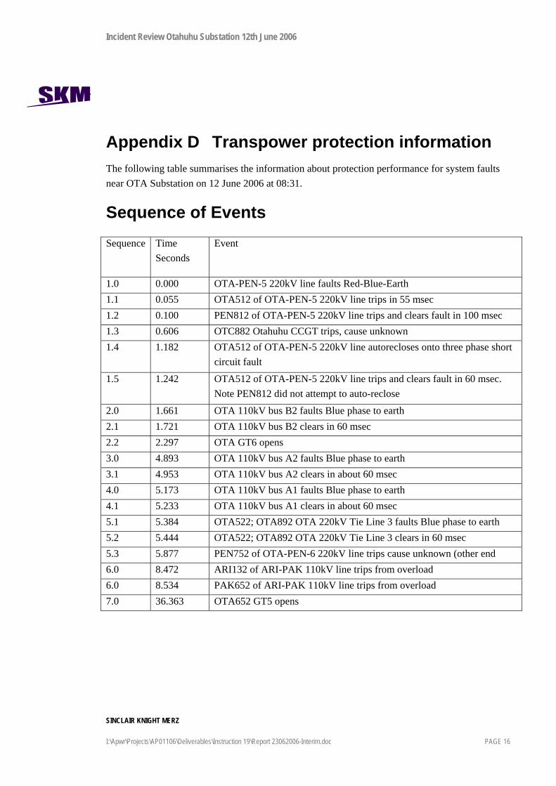
Appendix D Transpower protection information The following table summarises the information about protection performance for system faults near OTA Substation on 12 June 2006 at 08:31.
Sequence of Events Sequence Time
Seconds Event
1.0 0.000 OTA-PEN-5 220kV line faults Red-Blue-Earth 1.1 0.055 OTA512 of OTA-PEN-5 220kV line trips in 55 msec 1.2 0.100 PEN812 of OTA-PEN-5 220kV line trips and clears fault in 100 msec 1.3 0.606 OTC882 Otahuhu CCGT trips, cause unknown 1.4 1.182 OTA512 of OTA-PEN-5 220kV line autorecloses onto three phase short
circuit fault
1.5 1.242 OTA512 of OTA-PEN-5 220kV line trips and clears fault in 60 msec. Note PEN812 did not attempt to auto-reclose
2.0 1.661 OTA 110kV bus B2 faults Blue phase to earth 2.1 1.721 OTA 110kV bus B2 clears in 60 msec 2.2 2.297 OTA GT6 opens 3.0 4.893 OTA 110kV bus A2 faults Blue phase to earth 3.1 4.953 OTA 110kV bus A2 clears in about 60 msec 4.0 5.173 OTA 110kV bus A1 faults Blue phase to earth 4.1 5.233 OTA 110kV bus A1 clears in about 60 msec 5.1 5.384 OTA522; OTA892 OTA 220kV Tie Line 3 faults Blue phase to earth 5.2 5.444 OTA522; OTA892 OTA 220kV Tie Line 3 clears in 60 msec 5.3 5.877 PEN752 of OTA-PEN-6 220kV line trips cause unknown (other end 6.0 8.472 ARI132 of ARI-PAK 110kV line trips from overload 6.0 8.534 PAK652 of ARI-PAK 110kV line trips from overload 7.0 36.363 OTA652 GT5 opens
Incident Review Otahuhu Substation 12th June 2006
SINCLAIR KNIGHT MERZ
I:\Apwr\Projects\AP01106\Deliverables\Instruction 19\Report 23062006-Interim.doc PAGE 17
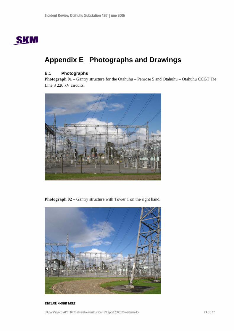
Appendix E Photographs and Drawings
E.1 Photographs Photograph 01 – Gantry structure for the Otahuhu – Penrose 5 and Otahuhu – Otahuhu CCGT Tie Line 3 220 kV circuits.
Photograph 02 – Gantry structure with Tower 1 on the right hand.

Incident Review Otahuhu Substation 12th June 2006
SINCLAIR KNIGHT MERZ
I:\Apwr\Projects\AP01106\Deliverables\Instruction 19\Report 23062006-Interim.doc PAGE 18
Photograph 03 – OHEW 512 across the Otahuhu – Penrose 5 220kV circuit and the A2 and B2 110 kV bus sections.
Photograph 04 – Section of OHEW 512 still attached to Tower 1.
Incident Review Otahuhu Substation 12th June 2006
SINCLAIR KNIGHT MERZ
I:\Apwr\Projects\AP01106\Deliverables\Instruction 19\Report 23062006-Interim.doc PAGE 19
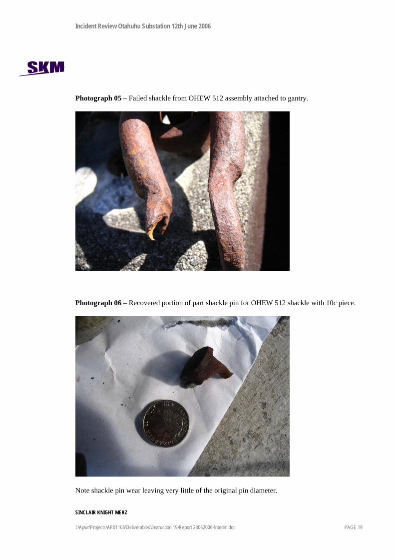
Photograph 05 – Failed shackle from OHEW 512 assembly attached to gantry.
Photograph 06 – Recovered portion of part shackle pin for OHEW 512 shackle with 10c piece.
Note shackle pin wear leaving very little of the original pin diameter.

Incident Review Otahuhu Substation 12th June 2006
SINCLAIR KNIGHT MERZ
I:\Apwr\Projects\AP01106\Deliverables\Instruction 19\Report 23062006-Interim.doc PAGE 20
Photograph 07 – Recovered shackle for attachment of OHEW 522 to the substation gantry earthwire peak. Note burn marks from fault current.
Photograph 08 – OHEW 522 gantry attachment point with shackle pin after the failure.

Incident Review Otahuhu Substation 12th June 2006
SINCLAIR KNIGHT MERZ
I:\Apwr\Projects\AP01106\Deliverables\Instruction 19\Report 23062006-Interim.doc PAGE 21
Photograph 09 – Recovered OHEW 522 shackle pin compared with the shackle pin of a recovered assembly from an adjacent gantry. Note the missing pin head of the OHEW 522 shackle pin and the extensive wear of the shackle pin from the adjacent gantry.

Incident Review Otahuhu Substation 12th June 2006
SINCLAIR KNIGHT MERZ
I:\Apwr\Projects\AP01106\Deliverables\Instruction 19\Report 23062006-Interim.doc PAGE 22
E.2 Drawings TX30005 Otahuhu Substation – Outdoor Switchyard Layout
Refer Figure 1 for details

Incident Review Otahuhu Substation 12th June 2006
SINCLAIR KNIGHT MERZ
I:\Apwr\Projects\AP01106\Deliverables\Instruction 19\Report 23062006-Interim.doc PAGE 23
Sketch Di552060614005.PDF
The attachment point is part of the earthwire peak of the switchyard gantry.
The failure occurred at 70 kN shackle pin attachment point connection.
Point of failure 70kN Shackle and dome headed shackle pin.

Incident Review Otahuhu Substation 12th June 2006
SINCLAIR KNIGHT MERZ
I:\Apwr\Projects\AP01106\Deliverables\Instruction 19\Report 23062006-Interim.doc PAGE 24
Appendix F Substation Layout Design –File Note
Incident Review Otahuhu Substation 12th June 2006
SINCLAIR KNIGHT MERZ
I:\Apwr\Projects\AP01106\Deliverables\Instruction 19\Report 23062006-Interim.doc PAGE 25

Incident Review Otahuhu Substation 12th June 2006
SINCLAIR KNIGHT MERZ
I:\Apwr\Projects\AP01106\Deliverables\Instruction 19\Report 23062006-Interim.doc PAGE 26


![Report on Ichchhapore substation Substation...2014/07/06 · Date:02/02/2018 Report on Ichchhapore substation Substation: SubstationEquipment: 1] PowerTransformer: A ...](https://static.fdocuments.us/doc/165x107/6082a7423c38c8542368e070/report-on-ichchhapore-substation-substation-20140706-date02022018-report.jpg)