
Incell Phonium Processor Design Specifications Dale Mansholt Aaron Drake Jonathan Scruggs Travis...
32
Incell Phonium Processor Design Specifications Dale Mansholt Aaron Drake Jonathan Scruggs Travis Svehla Incell Phonium Processor
-
Upload
jonathan-horton -
Category
Documents
-
view
216 -
download
1
Transcript of Incell Phonium Processor Design Specifications Dale Mansholt Aaron Drake Jonathan Scruggs Travis...

Incell Phonium Processor
Design Specifications
Dale Mansholt
Aaron Drake
Jonathan Scruggs
Travis Svehla
Incell Phonium Processor
Overview
• Project Review
• Development Tools
• Assembler Overview
• Emulator Overview
• Integrated Environment Overview
• Design Goals

Project Review
• Our clients are creating a digital signal processor (DSP) called the Janus Processor.
• We will be:– Creating an assembler for the Janus
instruction set– Creating an emulator for Janus Processor– Creating an environment that integrates the
assembler and emulator

Development Tools
• MS Visual C++ 7.0 for coding
• QT API for the integrated environment GUI
• MS Windows for testing
• Linux for testing
Assembler Overview
• Checks Janus assembly program for syntactical errors and jump instruction semantic errors
• Inserts no-op instructions as necessary to prevent data dependencies
• Translates assembly code into machine code and stores machine code to .bin file
• However, does not optimize assembly program

Janus Instruction Set
• RISC-Like• No complex instructions that reference
memory• All ALU operations are performed only on
registers• Has ‘i’ or ‘r’ at end of mnemonic if it can
access both memory and registers• The ‘i’ or ‘r’ comes before mnemonic for
DSP instructions
Janus Instruction Set
• There are three operand formats:– Basic register reference format
• It has a destination, source1, and source2 registers
– Absolute memory reference• It has a destination register and immediate value
– Immediate addressing of DSP-level instructions
• It has a destination, address1, and address2 registers

Janus Instruction Set
• Basic register reference format:
• Absolute memory reference format:
• Immediate address of DSP-level instructions format:
Opcode (6 bit) dr (3 bit) s1 (3 bit) s2 (3 bit) Unused (9 bit)
Opcode (6 bit) dr (2 bit) Immediate or absolute value (16 bit)
Opcode (6 bit) dr (2 bit) a1 (8 bit) a2 (8 bit)

Assembler Design
• Instruction Table– Text file containing the binary equivalents of the
mnemonic opcode• nop 000000000000000000000000• addr dr, s1, s2 000001DDDSSSSSSXXXXXXXXX
• Dependency Table– Will be a one dimensional array of N elements– Contains fields for the symbol of the registers
• Jump Table– Will be a table of variable size– Contains the addresses of the first instruction after
each label in the .sas files.

Assembler Design
• Three-pass assembler– Pass one
• Checks the assembly code for syntax errors
– Pass two• Removes data dependencies by inserting “nop” instructions• Saves the changes to a file with the extension “.sas”
– Pass three• Converts assembly code into machine code, which is saved
to a file with the extension “.bin”• Checks for jump instruction semantic errors

Assembler Subsystem
Assembler Interface
• One interface will be command driven on the console– Assemble Filename [starting Address] [/r]
• Filename – A “.as” file• [Starting Address] – The starting address of a
program• [/r] – removes all “nop” instructions from a “.as”
file
– Output will be sent to the console

Assembler Interface
• Example 1:

Assembler Interface
• Example 2:
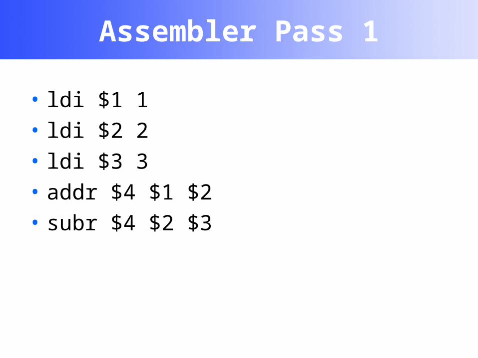
Assembler Pass 1
• ldi $1 1
• ldi $2 2
• ldi $3 3
• addr $4 $1 $2
• subr $4 $2 $3

Assembler Pass 2
• ldi $1 1• ldi $2 2• ldi $3 3• nop• nop• nop• addr $4 $1 $2• nop• nop• nop• nop• subr $4 $4 $3

Assembler Pass 3
• 001110010000000000000001• 001110100000000000000010• 001111100000000000000011• 000000000000000000000000• 000000000000000000000000• 000001100001010000000000• 000000000000000000000000• 000000000000000000000000• 000000000000000000000000• 000000000000000000000000• 000010100100011000000000
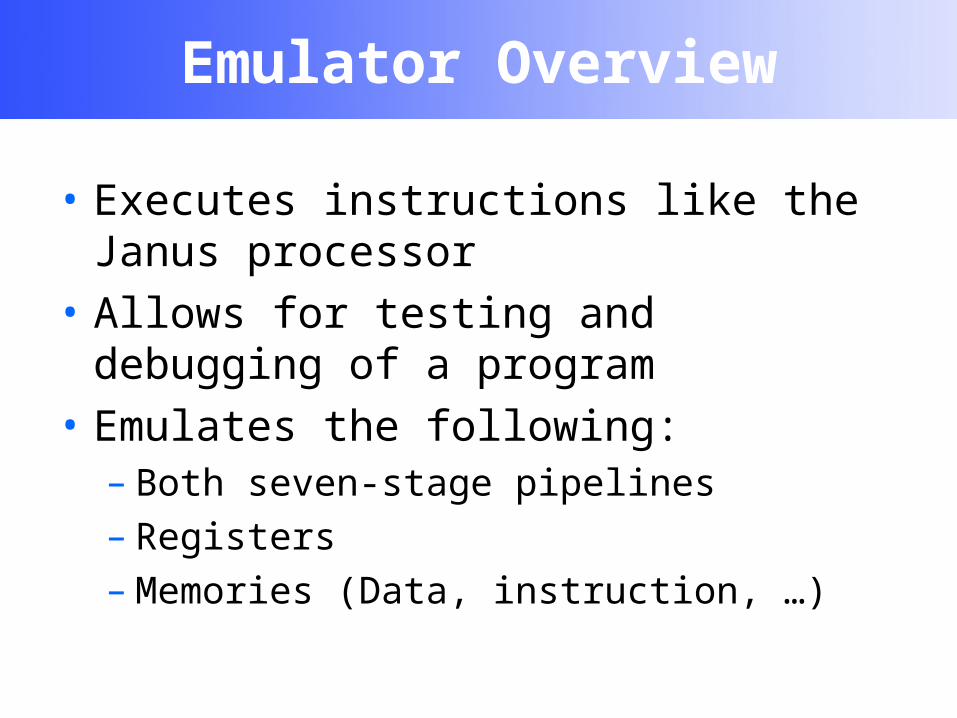
Emulator Overview
• Executes instructions like the Janus processor
• Allows for testing and debugging of a program
• Emulates the following:– Both seven-stage pipelines– Registers– Memories (Data, instruction, …)

Janus Processor

Janus Pipeline

Emulator Design
• Emulator Driver– The command line interface on the console
• Emulator Subsystem– Set up and coordinate the emulation process– Control the emulation directly in debug mode
• Pipeline– There are two pipelines– Execute the instructions– Has seven stages defined by the ECE team

Emulator Design
• Instruction– Stored in the instruction memory– “Tells” the pipeline what to do– Have an Operation Code (op-code) and operands
• Instruction Memory– One instruction memory per pipeline– Used to read and write instructions to
• Data– Information that is stored– Stored in registers and/or main memory

Emulator Design
• Data Memory– Two data memories per pipeline– Storage for variables
• Register– Used by pipelines to read and store data

Emulator Subsystem

Emulator Interface
• One interface will be command driven on the console– Emulate /load FileName [StartingAddress]– Emulate /emulate [OutputFileName]– Emulate /debug [OutputFileName]
[NumCycles]• [NumCycles] – Number of clock cycles to run

Emulator Interface
• Debugger:– s [NumCycles]
• Steps “NumCycles” clock cycles into the program. If “NumCycles” is not given, it is assumed to be one.
– d• Dumps memory at this time to the output file. Any successive
dumps will be appended to the file.
– g MemoryDeviceName• Gets the data from the specified address of the specified
device.
– q• Quits the debugger.

Emulator Interface
• Example:
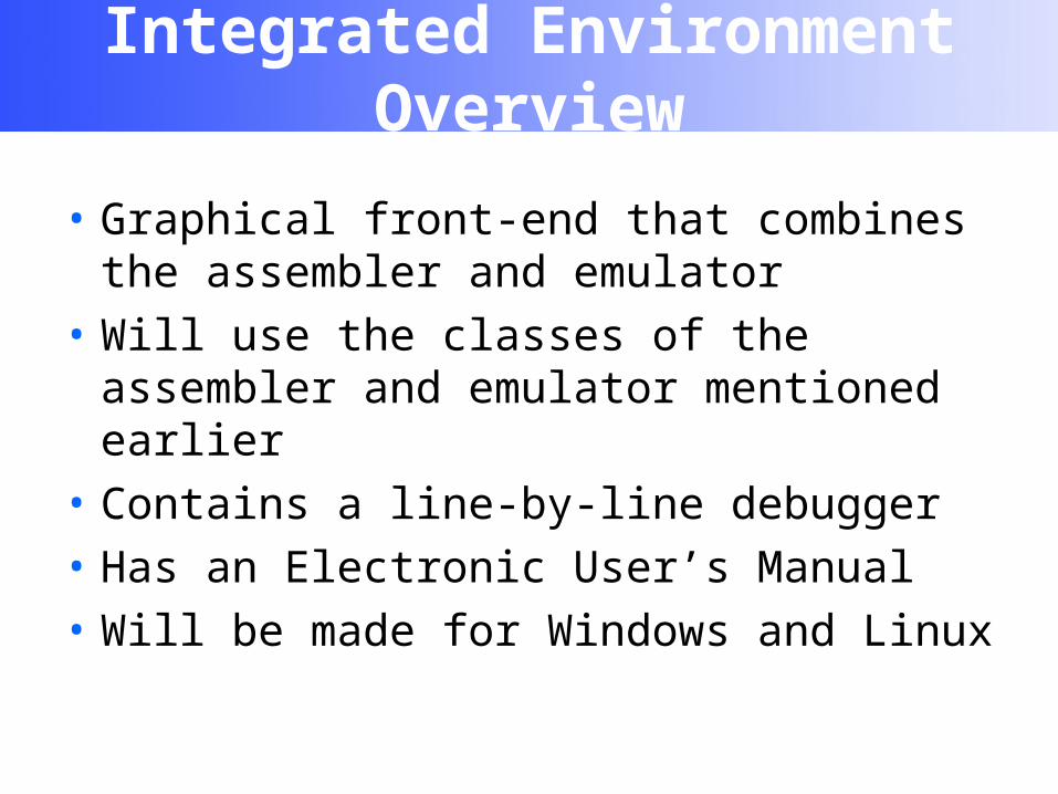
Integrated Environment Overview
• Graphical front-end that combines the assembler and emulator
• Will use the classes of the assembler and emulator mentioned earlier
• Contains a line-by-line debugger
• Has an Electronic User’s Manual
• Will be made for Windows and Linux

Integrated Environment Interface
• Prototype layout design:

Design Goals
• Feasibility– Must have the assembler and emulator done by the end of the
2003 Spring semester.
• Reliability– The assembler, emulator, and integrated environment should
produce output that is consistent with the instruction set specification
• Utility– The system should support the work of the user as best as
possible
• Robustness– The system should be able to handle invalid user input as well
as output appropriate error messages
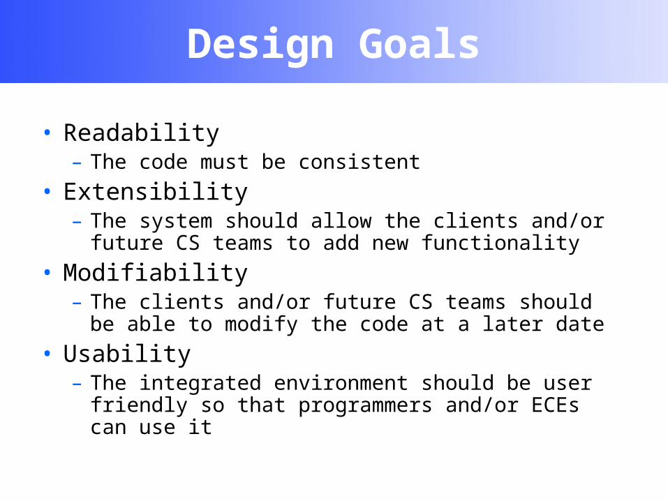
Design Goals
• Readability– The code must be consistent
• Extensibility– The system should allow the clients and/or future CS
teams to add new functionality
• Modifiability– The clients and/or future CS teams should be able to
modify the code at a later date
• Usability– The integrated environment should be user friendly so
that programmers and/or ECEs can use it

Questions?
• Our website:– http://solar.cs.siue.edu/incel/
• Janus Processor website:– http://www.siue.edu/~pness/janus.html