IN-VEHICLE REPAIR - The Mustang Source · 303-01A-6 Engine — 4.0L SOHC 303-01A-6 IN-VEHICLE...
18
303-01A-1 303-01A-1 Engine — 4.0L SOHC IN-VEHICLE REPAIR Special Tool(s) Cylinder Head Timing Tool, Crankshaft TDC 303-573 (T97T-6303-A) or Special Tool(s) equivalent Torque Wrench Extension 303-575 (T97T-6256-F) or equivalent Adapter for 303-577 303-576 (T97T-6256-D) or equivalent Socket, Camshaft Sprocket Nut 303-565 (T97T-6256-G) or equivalent Remover, Spark Plug Wire 303-106 (T74P-6666A) Holding Tool, Camshaft Sprocket 303-564 (T97T-6256-B) or equivalent Material Item Specification Adapter for 303-564 Silicone Brake Caliper ESE-M1C171-A 303-578 (T97T-6256-A) or Grease and Dielectric equivalent Compound XG-3-A Motorcraft SAE 5W-30 WSS-M2C929-A Premium Synthetic Blend Motor XO-5W30-QSP (in Canada Tensioner, Timing Chain Motorcraft SAE 5W-30 303-571 (T97T-6K254-A) or Super Premium Motor Oil equivalent CXO-5W30-LSP12) or equivalent Holding Tool, Camshaft 303-577 (T97T-6256-C) or equivalent (Continued) Copyright 2004, Ford Motor Company Last updated: 7/12/2005 2005 Mustang, 12/2004
Transcript of IN-VEHICLE REPAIR - The Mustang Source · 303-01A-6 Engine — 4.0L SOHC 303-01A-6 IN-VEHICLE...

303-01A-1 303-01A-1Engine — 4.0L SOHC
IN-VEHICLE REPAIRSpecial Tool(s)Cylinder Head
Timing Tool, Crankshaft TDC303-573 (T97T-6303-A) orSpecial Tool(s)equivalent
Torque Wrench Extension303-575 (T97T-6256-F) orequivalent
Adapter for 303-577303-576 (T97T-6256-D) orequivalent
Socket, Camshaft Sprocket Nut303-565 (T97T-6256-G) orequivalent
Remover, Spark Plug Wire303-106 (T74P-6666A)
Holding Tool, CamshaftSprocket303-564 (T97T-6256-B) orequivalent
Material
Item SpecificationAdapter for 303-564
Silicone Brake Caliper ESE-M1C171-A303-578 (T97T-6256-A) orGrease and DielectricequivalentCompoundXG-3-A
Motorcraft SAE 5W-30 WSS-M2C929-APremium Synthetic BlendMotorXO-5W30-QSP (in CanadaTensioner, Timing ChainMotorcraft SAE 5W-30303-571 (T97T-6K254-A) orSuper Premium Motor OilequivalentCXO-5W30-LSP12) orequivalent
Holding Tool, Camshaft303-577 (T97T-6256-C) orequivalent
(Continued)
Copyright 2004, Ford Motor CompanyLast updated: 7/12/2005 2005 Mustang, 12/2004

303-01A-2 303-01A-2Engine — 4.0L SOHC
IN-VEHICLE REPAIR (Continued)
Item Part Number Description Item Part Number Description
5 6065 RH cylinder head bolt (M8)1 6065 LH cylinder head bolt (M8)(2 required)(2 required)
6 6065 RH cylinder head bolt (M12)2 6065 LH cylinder head bolt (M12)(8 required)(8 required)
7 6049 RH cylinder head3 6M099 LH cylinder head
8 6051 RH cylinder head gasket4 6083 LH cylinder head gasket(Continued)
2005 Mustang, 12/2004
303-01A-3 303-01A-3Engine — 4.0L SOHC
IN-VEHICLE REPAIR (Continued)
RH sideRemoval
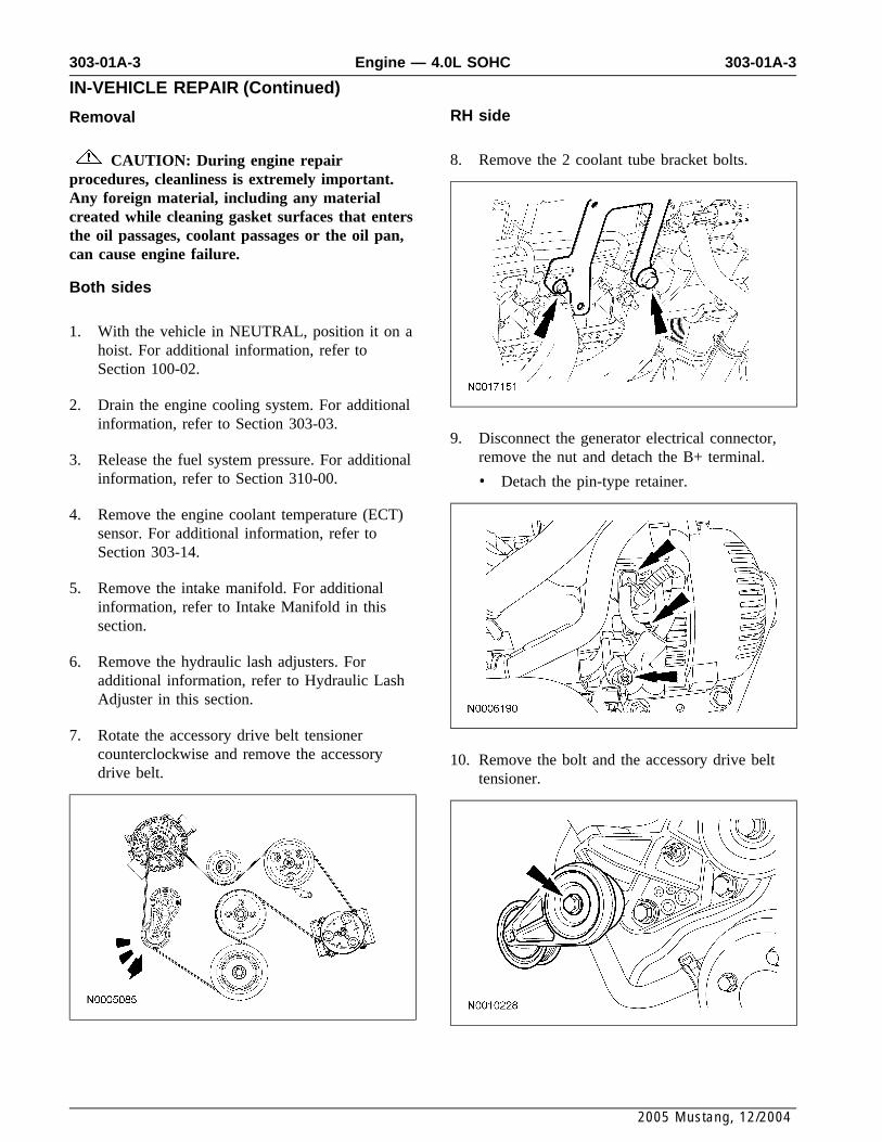
8. Remove the 2 coolant tube bracket bolts.CAUTION: During engine repairprocedures, cleanliness is extremely important.Any foreign material, including any materialcreated while cleaning gasket surfaces that entersthe oil passages, coolant passages or the oil pan,can cause engine failure.
Both sides
1. With the vehicle in NEUTRAL, position it on ahoist. For additional information, refer toSection 100-02.
2. Drain the engine cooling system. For additionalinformation, refer to Section 303-03.
9. Disconnect the generator electrical connector,remove the nut and detach the B+ terminal.3. Release the fuel system pressure. For additional
information, refer to Section 310-00. • Detach the pin-type retainer.
4. Remove the engine coolant temperature (ECT)sensor. For additional information, refer toSection 303-14.
5. Remove the intake manifold. For additionalinformation, refer to Intake Manifold in thissection.
6. Remove the hydraulic lash adjusters. Foradditional information, refer to Hydraulic LashAdjuster in this section.
7. Rotate the accessory drive belt tensionercounterclockwise and remove the accessory 10. Remove the bolt and the accessory drive beltdrive belt. tensioner.
2005 Mustang, 12/2004
303-01A-4 303-01A-4Engine — 4.0L SOHC
IN-VEHICLE REPAIR (Continued)
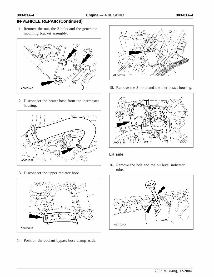
11. Remove the nut, the 2 bolts and the generatormounting bracket assembly.
15. Remove the 3 bolts and the thermostat housing.
12. Disconnect the heater hose from the thermostathousing.
LH side
16. Remove the bolt and the oil level indicatortube.
13. Disconnect the upper radiator hose.
14. Position the coolant bypass hose clamp aside.
2005 Mustang, 12/2004
303-01A-5 303-01A-5Engine — 4.0L SOHC
IN-VEHICLE REPAIR (Continued)
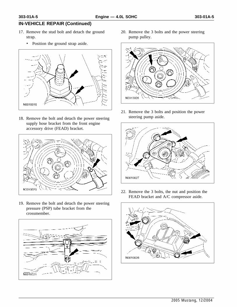
17. Remove the stud bolt and detach the ground 20. Remove the 3 bolts and the power steeringstrap. pump pulley.
• Position the ground strap aside.
21. Remove the 3 bolts and position the powersteering pump aside.18. Remove the bolt and detach the power steering
supply hose bracket from the front engineaccessory drive (FEAD) bracket.
22. Remove the 3 bolts, the nut and position theFEAD bracket and A/C compressor aside.
19. Remove the bolt and detach the power steeringpressure (PSP) tube bracket from thecrossmember.
2005 Mustang, 12/2004

303-01A-6 303-01A-6Engine — 4.0L SOHC
IN-VEHICLE REPAIR (Continued)
23. Remove the bolt and detach the starter motorwiring retainer bracket.
26. Remove the 4 bolts and the fuel rail andinjectors.
24. Remove the ground strap bolt and detach thewiring harness retainer from the backside of thecylinder head.
27. Separate the 6 fuel injectors from the fuel railand discard the O-ring seals.
28. NOTE: LH side shown, RH side similar.Both sides Remove the 4 catalytic converter-to-manifold
nuts.25. CAUTION: It is important to twist the
spark plug wire boots while pulling upwardto avoid possible damage to the spark plugwires.
Using the special tool, disconnect the 6 sparkplug wires from the spark plugs.
2005 Mustang, 12/2004

303-01A-7 303-01A-7Engine — 4.0L SOHC
IN-VEHICLE REPAIR (Continued)
29. NOTE: LH side shown, RH side similar. 32. CAUTION: The RH camshaft sprocketbolt is a LH-threaded bolt.Remove the 12 nuts and the exhaust manifolds
and gaskets. Using the special tool with the CamshaftSprocket Nut Socket 303-565, remove the RH• Discard the gaskets.camshaft bolt.
RH side33. Remove the RH side cassette bolt.
30. Remove the RH side hydraulic chain tensioner.
31. Install the special tools.
• Tighten the top clamp bolts to 10 Nm (89lb-in).
2005 Mustang, 12/2004

303-01A-8 303-01A-8Engine — 4.0L SOHC
IN-VEHICLE REPAIR (Continued)
34. CAUTION: Remove the camshaftsprocket from the timing chain to gainclearance to remove the cylinder head.
NOTE: Hold the timing chain and cassette witha rubber band to aid in removal and to preventthe timing chain from falling into the cylinderblock.
Remove the RH camshaft sprocket from thetiming chain. Install a rubber band around thecassette and the timing chain.
37. Remove the LH side camshaft sprocket bolt.
LH side
35. Remove the LH side hydraulic chain tensioner.38. Remove the LH side cassette bolt.
36. Install the special tools.
• Tighten to 10 Nm (89 lb-in).
2005 Mustang, 12/2004

303-01A-9 303-01A-9Engine — 4.0L SOHC
IN-VEHICLE REPAIR (Continued)
39. CAUTION: Remove the camshaftsprocket from the timing chain to gainclearance to remove the cylinder head.
NOTE: Hold the timing chain and cassette witha rubber band to aid in removal and to preventthe timing chain from falling into the cylinderblock.
Remove the LH camshaft sprocket from thetiming chain. Install a rubber band around thecassette and the timing chain.
41. CAUTION: Do not use metal scrapers,wire brushes, power abrasive discs or otherabrasive means to clean the sealing surfaces.These tools cause scratches and gouges thatmake leak paths. Use a plastic scraping toolto remove all traces of the head gasket.
Clean and inspect the mating surfaces.
42. Inspect the cylinder head and the cylinder blockfor flatness. For additional information, refer toSection 303-00.
Both sidesInstallation
40. CAUTION: To avoid damage to the Both sidestiming chain cassette, an assistant will berequired to help lift the cylinder head from 1. Position the cylinder head gaskets on the block.the vehicle.
CAUTION: On the RH side, whenlifting the cylinder head, be careful to avoidcontacting the A/C tube.
NOTE: New cylinder head bolts must beinstalled. They are a torque-to-yield design andcannot be reused.
Remove the cylinder heads.
• Remove the cylinder head bolts in thesequence shown. Discard all the bolts.
• Remove and discard the head gaskets.
2005 Mustang, 12/2004
303-01A-10 303-01A-10Engine — 4.0L SOHC
IN-VEHICLE REPAIR (Continued)
RH side
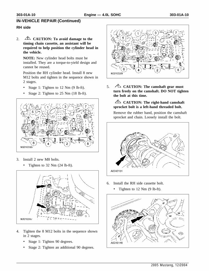
2. CAUTION: To avoid damage to thetiming chain cassette, an assistant will berequired to help position the cylinder head inthe vehicle.
NOTE: New cylinder head bolts must beinstalled. They are a torque-to-yield design andcannot be reused.
Position the RH cylinder head. Install 8 newM12 bolts and tighten in the sequence shown in2 stages.
5. CAUTION: The camshaft gear must• Stage 1: Tighten to 12 Nm (9 lb-ft).turn freely on the camshaft. DO NOT tighten
• Stage 2: Tighten to 25 Nm (18 lb-ft).the bolt at this time.
CAUTION: The right-hand camshaftsprocket bolt is a left-hand threaded bolt.
Remove the rubber band, position the camshaftsprocket and chain. Loosely install the bolt.
3. Install 2 new M8 bolts.
• Tighten to 32 Nm (24 lb-ft).
6. Install the RH side cassette bolt.
• Tighten to 12 Nm (9 lb-ft).
4. Tighten the 8 M12 bolts in the sequence shownin 2 stages.
• Stage 1: Tighten 90 degrees.
• Stage 2: Tighten an additional 90 degrees.
2005 Mustang, 12/2004

303-01A-11 303-01A-11Engine — 4.0L SOHC
IN-VEHICLE REPAIR (Continued)
LH side
7. CAUTION: To avoid damage to thetiming chain cassette, an assistant will berequired to help position the cylinder head inthe vehicle.
NOTE: New cylinder head bolts must beinstalled. They are a torque-to-yield design andcannot be reused.
Position the LH cylinder head. Install 8 newM12 bolts and tighten in the sequence shown in2 stages.
10. CAUTION: The camshaft gear must• Stage 1: Tighten to 12 Nm (9 lb-ft).turn freely on the camshaft. DO NOT tighten
• Stage 2: Tighten to 25 Nm (18 lb-ft).the bolt at this time.
Remove the rubber band, position the camshaftsprocket and chain. Loosely install the bolt.
8. Install 2 new M8 bolts.
• Tighten to 32 Nm (24 lb-ft).
11. Install the LH side cassette bolt.
• Tighten to 19 Nm (14 lb-ft).
9. Tighten the 8 M12 bolts in the sequence shownin 2 stages.
• Stage 1: Tighten 90 degrees.
• Stage 2: Tighten an additional 90 degrees.
2005 Mustang, 12/2004
303-01A-12 303-01A-12Engine — 4.0L SOHC
IN-VEHICLE REPAIR (Continued)
Both sides
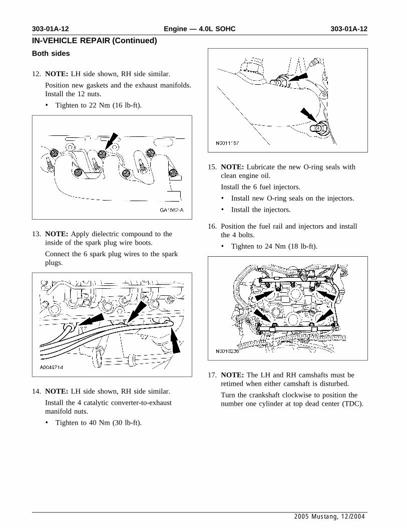
12. NOTE: LH side shown, RH side similar.
Position new gaskets and the exhaust manifolds.Install the 12 nuts.
• Tighten to 22 Nm (16 lb-ft).
15. NOTE: Lubricate the new O-ring seals withclean engine oil.
Install the 6 fuel injectors.
• Install new O-ring seals on the injectors.
• Install the injectors.
16. Position the fuel rail and injectors and install13. NOTE: Apply dielectric compound to the the 4 bolts.
inside of the spark plug wire boots. • Tighten to 24 Nm (18 lb-ft).Connect the 6 spark plug wires to the sparkplugs.
17. NOTE: The LH and RH camshafts must beretimed when either camshaft is disturbed.
14. NOTE: LH side shown, RH side similar. Turn the crankshaft clockwise to position theInstall the 4 catalytic converter-to-exhaust number one cylinder at top dead center (TDC).manifold nuts.
• Tighten to 40 Nm (30 lb-ft).
2005 Mustang, 12/2004

303-01A-13 303-01A-13Engine — 4.0L SOHC
IN-VEHICLE REPAIR (Continued)
18. CAUTION: Do not rotate the enginecounterclockwise. Rotating the enginecounterclockwise will result in incorrecttiming of the engine.
NOTE: The special tool must be installed onthe damper and should contact the engineblock, this positions the engine at TDC.
Install the special tool.
21. Tighten the top clamp bolts to 10 Nm (89lb-in).
19. NOTE: Leave the top 2 special tool clampbolts loose.
Install the special tools on the rear of the RHcylinder head.
22. Install the special tool.
20. NOTE: The camshaft timing slots areoff-center.
Position the camshaft timing slots below thecenterline of the camshaft to correctly fit thespecial tools, and install the special tools on thefront of the RH cylinder head.
2005 Mustang, 12/2004
303-01A-14 303-01A-14Engine — 4.0L SOHC
IN-VEHICLE REPAIR (Continued)
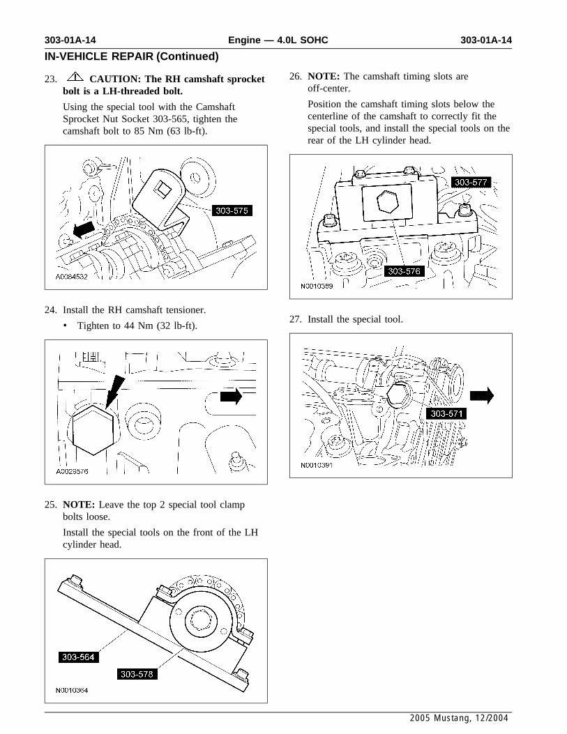
26. NOTE: The camshaft timing slots are23. CAUTION: The RH camshaft sprocketoff-center.bolt is a LH-threaded bolt.Position the camshaft timing slots below theUsing the special tool with the Camshaftcenterline of the camshaft to correctly fit theSprocket Nut Socket 303-565, tighten thespecial tools, and install the special tools on thecamshaft bolt to 85 Nm (63 lb-ft).rear of the LH cylinder head.
24. Install the RH camshaft tensioner.27. Install the special tool.
• Tighten to 44 Nm (32 lb-ft).
25. NOTE: Leave the top 2 special tool clampbolts loose.
Install the special tools on the front of the LHcylinder head.
2005 Mustang, 12/2004

303-01A-15 303-01A-15Engine — 4.0L SOHC
IN-VEHICLE REPAIR (Continued)
28. Tighten the bolts.
1 Tighten the special tool top 2 clamp bolts to10 Nm (89 lb-in).
2 Tighten the camshaft bolt to 85 Nm (63lb-ft).
31. Position the starter motor wiring retainerbracket and install the bolt.
• Tighten to 40 Nm (30 lb-ft).
29. Install the LH camshaft tensioner.
• Tighten to 44 Nm (32 lb-ft).
32. Position the front engine accessory drive(FEAD) bracket and A/C compressor. Install the3 bolts and the nut.
• Tighten to 47 Nm (35 lb-ft).
LH side
30. Position the ground strap and install the bolt.
• Tighten to 40 Nm (30 lb-ft).
• Attach the wiring harness retainer to thebackside of the cylinder head.
2005 Mustang, 12/2004
303-01A-16 303-01A-16Engine — 4.0L SOHC
IN-VEHICLE REPAIR (Continued)
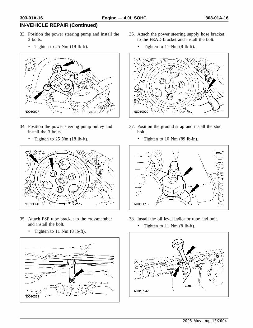
33. Position the power steering pump and install the 36. Attach the power steering supply hose bracket3 bolts. to the FEAD bracket and install the bolt.
• Tighten to 25 Nm (18 lb-ft). • Tighten to 11 Nm (8 lb-ft).
34. Position the power steering pump pulley and 37. Position the ground strap and install the studinstall the 3 bolts. bolt.
• Tighten to 25 Nm (18 lb-ft). • Tighten to 10 Nm (89 lb-in).
35. Attach PSP tube bracket to the crossmember 38. Install the oil level indicator tube and bolt.and install the bolt. • Tighten to 11 Nm (8 lb-ft).• Tighten to 11 Nm (8 lb-ft).
2005 Mustang, 12/2004

303-01A-17 303-01A-17Engine — 4.0L SOHC
IN-VEHICLE REPAIR (Continued)
RH side 42. Connect the heater hose to the thermostathousing.
39. NOTE: Inspect the O-ring seal. Install a newO-ring seal if necessary.
Position the thermostat housing and install the 3bolts.
• Tighten to 11 Nm (8 lb-ft).
43. Position the generator mounting bracketassembly and install the 2 bolts and the nut.
• Tighten to 47 Nm (35 lb-ft).
40. Position the coolant bypass hose clamp.
44. Install the accessory drive belt tensioner andbolt.
• Tighten to 47 Nm (35 lb-ft).
41. Install the upper radiator hose.
2005 Mustang, 12/2004
303-01A-18 303-01A-18Engine — 4.0L SOHC
IN-VEHICLE REPAIR (Continued)
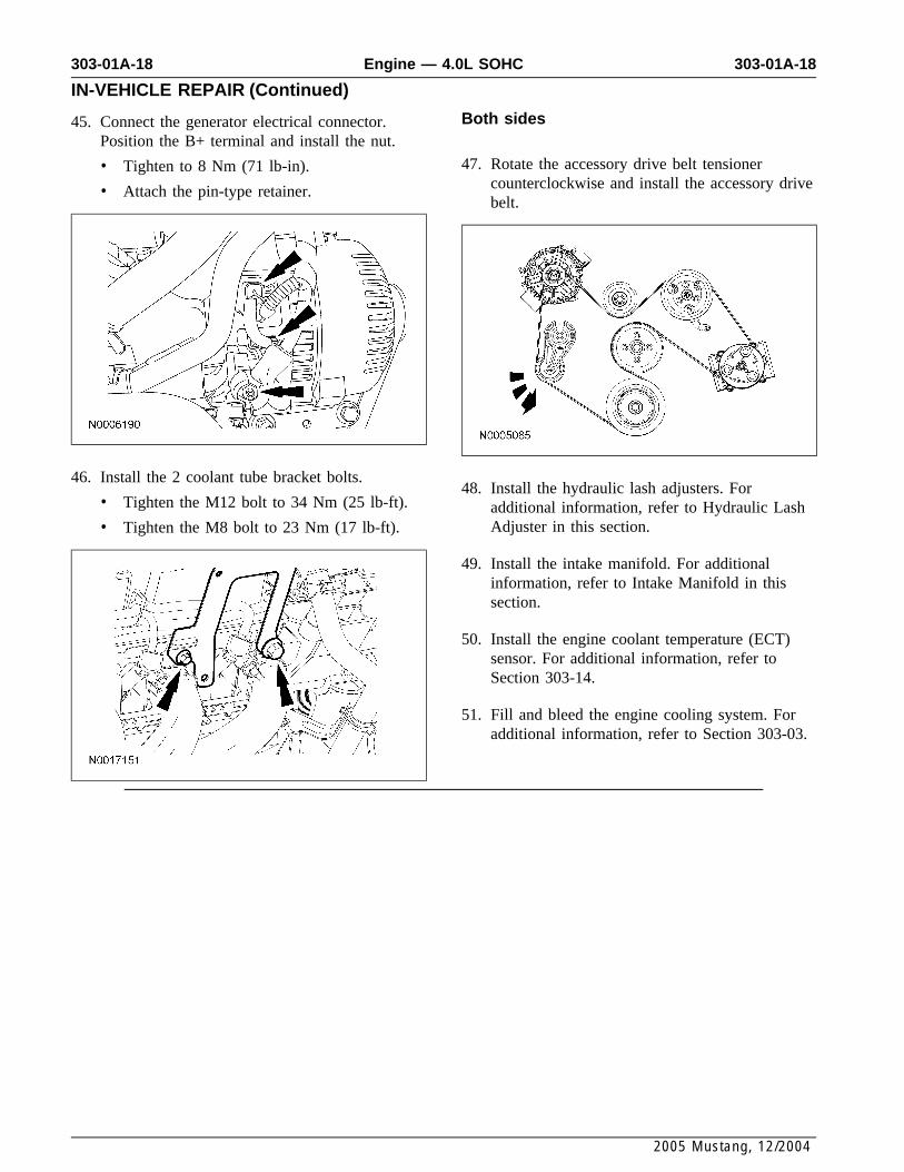
Both sides45. Connect the generator electrical connector.Position the B+ terminal and install the nut.
47. Rotate the accessory drive belt tensioner• Tighten to 8 Nm (71 lb-in).counterclockwise and install the accessory drive• Attach the pin-type retainer.belt.
46. Install the 2 coolant tube bracket bolts.48. Install the hydraulic lash adjusters. For
• Tighten the M12 bolt to 34 Nm (25 lb-ft). additional information, refer to Hydraulic LashAdjuster in this section.• Tighten the M8 bolt to 23 Nm (17 lb-ft).
49. Install the intake manifold. For additionalinformation, refer to Intake Manifold in thissection.
50. Install the engine coolant temperature (ECT)sensor. For additional information, refer toSection 303-14.
51. Fill and bleed the engine cooling system. Foradditional information, refer to Section 303-03.
2005 Mustang, 12/2004