In uence of Nano{Wear of Tool on the Magnitude of Cutting ...kdm.p.lodz.pl/articles/2012/1_...
10
Mechanics and Mechanical Engineering Vol. 16, No. 1 (2012) 5–13 c ⃝ Technical University of Lodz Influence of Nano–Wear of Tool on the Magnitude of Cutting Forces Andrzej Lorenc Institute of Machine Tools and Production Engineering Technical University of L´ od´ z [email protected] Anna S lawi´ nska Piotr J´ o´ zwiak Department of Vehicles and Fundamentals of Machine Design Technical University of L´ od´ z [email protected] [email protected] Received (18 October 2012) Revised (19 December 2012) Accepted (5 January 2013) The paper presents results of research by means of Scanning Probe Microscopy (SPM), the rake face wear of inserts covered with titanium nitride. The influence of nano–wear on the magnitude of cutting force has been described. Keywords : SPM microscopy, nano–wear, coatings topography, cutting forces 1. Introduction Every day new materials are being formed, weighting less and at the same time having higher strength parameters, however at the same time being more difficult in machining. Due to increasing machining requirements new tool materials are being created. Tool contour and angles change, excessive wear of a cutting tool is not allowed. The parameters of machining increase as well as tool life. The paper presents the nano–wear of cutting inserts. The nano–wear has the influence on the cutting forces during turning and therefore effect on the machined surface i.e. for the surface shape and roughness. Using scanning probe microscopy (AFM and STM) we are able to investigate the wear of inserts covered with TiN, TiC [4 ] or other compounds as well as ceramic inserts. Knowing the real time of the wear of applied layers upon examination we conducted the investigation on the influence of
-
Upload
nguyenkhanh -
Category
Documents
-
view
219 -
download
3
Transcript of In uence of Nano{Wear of Tool on the Magnitude of Cutting ...kdm.p.lodz.pl/articles/2012/1_...

Mechanics and Mechanical Engineering
Vol. 16, No. 1 (2012) 5–13c⃝ Technical University of Lodz
Influence of Nano–Wear of Tool on the Magnitudeof Cutting Forces
Andrzej Lorenc
Institute of Machine Tools and ProductionEngineering
Technical University of [email protected]
Anna S lawinskaPiotr Jozwiak
Department of Vehicles and Fundamentalsof Machine Design
Technical University of [email protected]@p.lodz.pl
Received (18 October 2012)
Revised (19 December 2012)
Accepted (5 January 2013)
The paper presents results of research by means of Scanning Probe Microscopy (SPM),the rake face wear of inserts covered with titanium nitride. The influence of nano–wearon the magnitude of cutting force has been described.
Keywords: SPM microscopy, nano–wear, coatings topography, cutting forces
1. Introduction
Every day new materials are being formed, weighting less and at the same timehaving higher strength parameters, however at the same time being more difficultin machining. Due to increasing machining requirements new tool materials arebeing created. Tool contour and angles change, excessive wear of a cutting tool isnot allowed. The parameters of machining increase as well as tool life. The paperpresents the nano–wear of cutting inserts. The nano–wear has the influence onthe cutting forces during turning and therefore effect on the machined surface i.e.for the surface shape and roughness. Using scanning probe microscopy (AFM andSTM) we are able to investigate the wear of inserts covered with TiN, TiC [4 ] orother compounds as well as ceramic inserts. Knowing the real time of the wear ofapplied layers upon examination we conducted the investigation on the influence of

6 Lorenc, A., S lawinska, A., Jozwiak P.
nano–wear on the magnitude of cutting forces. In the next stage of research we willcheck the influence of nano–wear on the machined surface quality.
2. Conditions of conducting research and samples
Commercially available six blade cutting insert, marked as WNMG 060404–WF hasbeen used in the research.
The sample: titanium nitride layer on a substrate of sintered carbide,
Cutting tests have been carried out with the following parameters of machining:
• cutting speed: vc = 300 m/min
• feed rate: f = 0,05 mm/rev, f = 0,1 mm/rev, f = 2 mm/rev, f = 3 mm/rev
• depth of cut: a = 1 mm
• machined material: C45 steel, 30 HRC ±2
Conditions of conducting the research:
• STM (scanning tunneling microscope), constant current mode, current of0,80 nA, the needle with a diameter of 0.25 mm, wire prepared of Ir-Pt (irid-ium 10%, platinum 90%) by cutting with a wire cutter,
• scanning direction: along the x–axis and y–axis
• scanning was performed at atmospheric pressure and room temperature.
The wear of the rake face of the surface layer of the sample was the subjectof investigation. Measurements were made on the surface layer of samples, beforemachining and after periods of turning lasting respectively: 36 s, 1 min 12 s, 2 min24 s, 4 min 48 s. Selected results have been included in the paper.
3. The research stand
Research was carried out on the stand presented in Fig.1.
Machine cutting tests have been conducted on the numerically controlled latheSL10 made by HAAS. Measurement signals from Kistler’s force gauge type 9121,Kistler’s amplifier type 5070 A and A/C converter card type 2855A4 were trans-ferred and recorded on a PC hard drive using Kistler’s DynoWare program. Fig.2 presents the distribution of forces during machine cutting, explains denotationsused in experimental courses of machine cutting forces. The following denotationswere adopted: Fz = Fc – cutting force in z direction, Ft = Fy – feed force, Fp =Fx – thrust force.
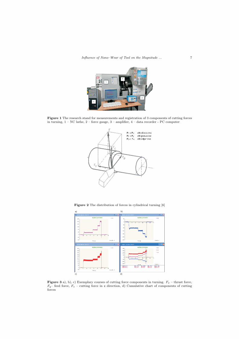
The exemplary courses of cutting forces components obtained from the researchpresents Fig. 3.
Influence of Nano–Wear of Tool on the Magnitude ... 7
Figure 1 The research stand for measurements and registration of 3 components of cutting forcesin turning, 1 – NC lathe, 2 – force gauge, 3 – amplifier, 4 – data recorder - PC computer
Figure 2 The distribution of forces in cylindrical turning [6]
a) b)
c) d)
Figure 3 a), b), c) Exemplary courses of cutting force components in turning. Fx – thrust force,Fy– feed force, Fz – cutting force in z direction, d) Cumulative chart of components of cuttingforces

8 Lorenc, A., S lawinska, A., Jozwiak P.
4. Results of the research
Fig. 4 presents three dimensional topography of the surface of the new insert coveredwith a layer of titanium nitride (TiN). Grains of a varying size in the range from700 to 1000 nm with oval rounded edges form the top layer [1].
The study was conducted using a number of scan areas, each surface scannedalong the x–axis and the y–axis. Figs 4, 7–11 shows the results of measuring thesurface layer of examined inserts. Figures marked with a letter b) show the two–dimensional surface with a marked measuring x and y axes. Figures marked withthe letter c) respectively show the micro–geometry of the surface measured alongthe x and y axis. Figs marked with a letter c) present the three–dimensional surfaceof the examined samples. The measured values are given in nanometers.
4.1. The wear of insert covered with TiN layer
Fig. 5 presents the wear traces of the sample after 1 minute 12 seconds of operation.Still can be observed hilly structure. The height of grains with traces of wear variesin the range of 700–780 nm.
a) b)
c)
Figure 4 a), b) Image of TiN layer. The new insert, c) Surface geometry along x, y axis

Influence of Nano–Wear of Tool on the Magnitude ... 9
Table 1 Mean values of components of the cutting force after 1 min 12 sec turning
FeedConstant parameters Cutting forces[N]
– mean valueαv V c material Fx Fy Fz
V f1= 0,05mm/rev
1mm 300 m/min C45
82 100 48
V f2= 0,1 mm/rev 110 152 69V f3= 0,2 mm/rev 115 198 128V f4= 0,3 mm/rev 210 205 167
a) b)
c)
Figure 5 a), b) Abrasive wear of the tool (TiN) after 1 minute 12 sec. of cutting,c) Geometry ofsurface along x, y axis
a) b)
Figure 6 a) Traces of cutting tool wear after 1 min. 12 sec. of work, b) after 2 min. 24 sec. ofturning

10 Lorenc, A., S lawinska, A., Jozwiak P.
5 10 15 20 25 30
-300
-200
-100
0
100
200
300
400
500
600
Time [s]
F [N]y
F [N]z
F [N]x
feed steel C45
Figure 7 The cumulative chart of components of cutting forces - the first test of turning
a) b)
c)
Figure 8 a), b) Abrasive wear of the tool (TiN) after 2 min 24 sec of work, c) Geometry of surfacealong x, y axis

Influence of Nano–Wear of Tool on the Magnitude ... 11
Table 2 Mean values of components of the cutting force after 4 min 48 of turning
Feed rateConstant parameters Cutting force [N]
– mean valueαv V c material Fx Fy Fz
V f1= 0,05 mm/rev
1mm 300 m/min C45
82 138 42V f2= 0,1 mm/rev 93 182 70V f3= 0,2 mm/rev 132 238 132V f4= 0,3 mm/rev 205 269 221
5 10 15 20 25 30
-300
-200
-100
0
100
200
300
400
500
600
700
800
Time [s]
posuw stal C45
Cycle No.: 1
Fx [N]
Fy [N]
Fz [N]
Time [s]
F [N]x
F [N]y
F [N]z
feed steel C45
Figure 9 The cumulative chart of components of cutting forces – the second test of turning
Photographs of wear traces of inserts after the time of turning equal to 1 minute12 seconds and 2 minutes 24 seconds are presented on the Fig. 6.
After 2 minutes, 24 seconds of operation the granular structure disappearedfrom topography and a terraced structure formed (Fig. 8). Tabs 1, 2, 3, present thevalues of components of the cutting forces generated by the turning of C45 steel.Turning conditions: constant cutting speed of 300 m / min and a constant depthof cut equal to 1 mm for different feed values. Mean values of the cutting forcecomponents were read from the graph (Figs 7, 9, 11).
Table 3
Feed rateConstant parameters Cutting force [N]
– mean valueαv V c material Fx Fy Fz
V f1= 0,05mm/rev
1 mm 300 m/min C45
98 143 120
V f2= 0,1 mm/rev 102 170 148V f3= 0,2 mm/rev 160 260 210V f4= 0,3 mm/rev 260 280 362

12 Lorenc, A., S lawinska, A., Jozwiak P.
a)
b)
c)
Figure 10 a), b) Abrasive wear of the tool (TiN) after 4 min 48 sec of work, c) Geometry ofsurface along x, y axis
posuw stal C45
5 10 15 20 25 30
-300
-200
-100
0
100
200
300
400
500
600
700
Time [s]Cycle No.: 1
Fx [N]
Fy [N]
Fz [N]
feed steel C45
F [N]x
F [N]y
F [N]z
Figure 11 The cumulative chart of components of cutting forces - the fourth test of turning
After 4 minutes, 48 seconds of operation TiN coating has been worn off (Fig.10). Remained visible structure of sintered carbide of a height varying in the rangeof 150–220 nm [5].
5. Conclusions
1. The process of the abrasive wear of the cutting insert covered with TiN layerruns in an analogical manner during turning on conventional machines [3,4].
2. After 4 minutes 48 seconds of cutting it can be seen the lack of TiN layer onthe measured surface.
3. By comparing the force charts (Fig. 7. Tab. 1., Fig. 9., Tab. 2, Fig. 11,Tab. 3.) it can be stated that during the cutting process occurs the abrasion of TiNlayer what generates the increase of values of all components of the cutting force.
The research stand has been created under the project no WND–RPLD–05–03–

Influence of Nano–Wear of Tool on the Magnitude ... 13
00–00–59/08 : ”Adaptation of the educational infrastructure of the Faculty of Me-chanical Engineering of Technical University of Lodz to predict needs and expecta-tions of the labour market of the region of Lodz through the purchase of the equipmentpredicted for the modern teaching methods”.
References
[1] Chen, Z. Y., Castleman, A. W.: Growth of Titanium Nitride: From Cluster toMicrocrystals, J. Chem. Phys., 98 (1), pp 231–235, 1993.
[2] Howland, R., Benatar, L.:A Practical Guide to Scanning Probe Microscopy,Warszawa, 2002.
[3] S lawinska, A., Lorenc, A., Jozwiak, P: Okreslenie zuzycia warstw wierzchnichp lytek pokrywanych azotkiem tytanu przy pomocy mikroskopu tunelowego, XXIIISympozjon Podstaw Konstrukcji Maszyn, Rzeszow - Przemysl , Materia ly Konferen-cyjne – Suplement, p. 26–30, 2007.
[4] Lorenc, A., S lawinska, Jozwiak, P.: Proby okreslenia za pomoc mikroskopiiSPM wybranych parametrow warstwy wierzchniej pow lok nak ladanych na ostrzaskrawajace, Obrobka Skrawaniem, Nauka a Przemys l, Vol. 5 p. 427 – 434, ISBN 978–83–61101–10–9, 2011.
[5] Meldner, B., Darlewski, J.: Narzedzia skrawajace w zautomatyzowanej produkcji,WNT, ISBN 83–204–1308, 1991.
[6] PN–87/M–01020, PN–83/M–58350