In This Appendix · 0008 = Ch1/Fn1 Reset 0009 = Ch1/Fn2 Reset 000A = Ch2/Fn1 Reset 000B = Ch2/Fn2...
21
S YSTEM F UNCTIONS B B APPENDIX APPENDIX APPENDIX In This Appendix... System Functions ....................................................................................................... B-2 Write All Registers (IBoxes) ....................................................................................... B-3 Write All Registers (DL-PLC)...................................................................................... B-4 Write One Register (IBoxes)...................................................................................... B-5 Write One Register (DL-PLC) .................................................................................... B-6 Read All Registers (IBoxes)........................................................................................ B-7 Read All Registers (DL-PLC) ...................................................................................... B-8 Read One Register (IBoxes) ...................................................................................... B-9 Read One Register (DL-PLC) ................................................................................... B-10 Read Error Code (IBoxes) ........................................................................................ B-11 Read Error Code (DL-PLC)....................................................................................... B-12 System Functions Examples Overview .................................................................... B-13 Single Channel Simulating Retentive Quad Counter ............................................ B-14 Dual Channel Simulating Retentive Quad Counters .............................................. B-17 Reading CTRIO Internal Registers ........................................................................... B-20
Transcript of In This Appendix · 0008 = Ch1/Fn1 Reset 0009 = Ch1/Fn2 Reset 000A = Ch2/Fn1 Reset 000B = Ch2/Fn2...
SyStem FunctionS BBAppendixAppendixAppendix
In This Appendix...System Functions ....................................................................................................... B-2
Write All Registers (IBoxes) ....................................................................................... B-3
Write All Registers (DL-PLC)...................................................................................... B-4
Write One Register (IBoxes) ...................................................................................... B-5
Write One Register (DL-PLC) .................................................................................... B-6
Read All Registers (IBoxes) ........................................................................................ B-7
Read All Registers (DL-PLC) ...................................................................................... B-8
Read One Register (IBoxes) ...................................................................................... B-9
Read One Register (DL-PLC) ................................................................................... B-10
Read Error Code (IBoxes) ........................................................................................ B-11
Read Error Code (DL-PLC) ....................................................................................... B-12
System Functions Examples Overview .................................................................... B-13
Single Channel Simulating Retentive Quad Counter ............................................ B-14
Dual Channel Simulating Retentive Quad Counters .............................................. B-17
Reading CTRIO Internal Registers ........................................................................... B-20
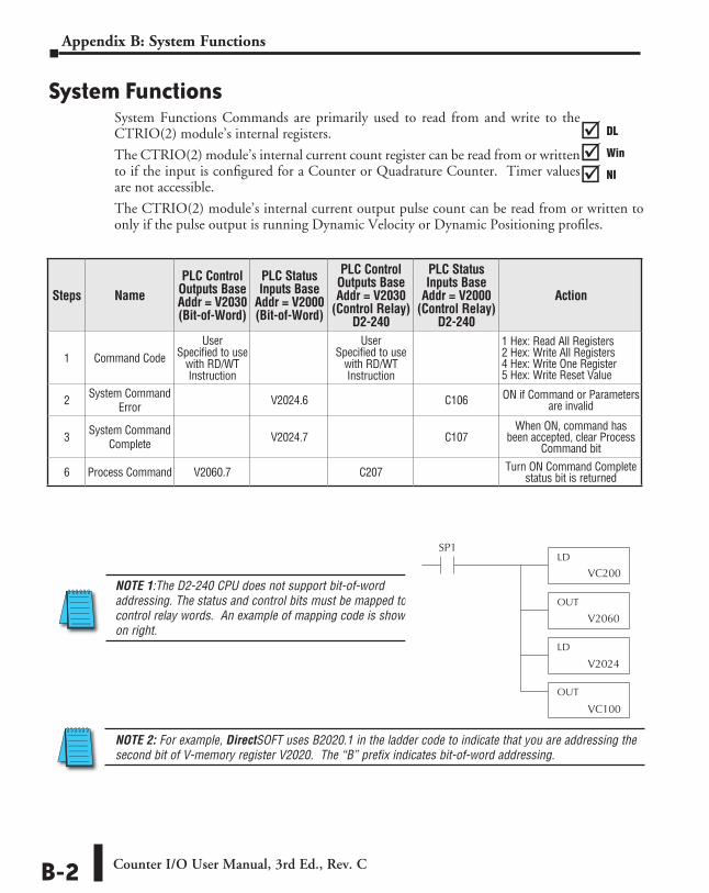
System FunctionsSystem Functions Commands are primarily used to read from and write to the CTRIO(2) module’s internal registers.
The CTRIO(2) module’s internal current count register can be read from or written to if the input is configured for a Counter or Quadrature Counter. Timer values are not accessible.
The CTRIO(2) module’s internal current output pulse count can be read from or written to only if the pulse output is running Dynamic Velocity or Dynamic Positioning profiles.
Steps NamePLC Control
Outputs Base Addr = V2030 (Bit-of-Word)
PLC Status Inputs Base
Addr = V2000 (Bit-of-Word)
PLC Control Outputs Base Addr = V2030
(Control Relay) D2-240
PLC Status Inputs Base
Addr = V2000 (Control Relay)
D2-240
Action
1 Command CodeUser
Specified to use with RD/WT Instruction
User Specified to use
with RD/WT Instruction
1 Hex: Read All Registers 2 Hex: Write All Registers 4 Hex: Write One Register 5 Hex: Write Reset Value
2 System Command Error V2024.6 C106 ON if Command or Parameters
are invalid
3 System Command Complete V2024.7 C107
When ON, command has been accepted, clear Process
Command bit
6 Process Command V2060.7 C207 Turn ON Command Complete status bit is returned
NOTE 1:The D2-240 CPU does not support bit-of-word addressing. The status and control bits must be mapped to control relay words. An example of mapping code is shown on right.
LD
OUT
LD
OUT
VC200
SP1
V2060
V2024
VC100
NOTE 2: For example, DirectSOFT uses B2020.1 in the ladder code to indicate that you are addressing the second bit of V-memory register V2020. The “B” prefix indicates bit-of-word addressing.
DL
Win
NI
���
DL
Win
NI
���
DL
Win
NI
���
DL
Win
NI
���
Counter I/O User Manual, 3rd Ed., Rev. CB-2
Appendix B: System Functions
Start
System Function(Write All Registers)
(IBoxes)
Yes
No
[SysCmdComplete]= ON?
Yes
No
PARAMETERS:
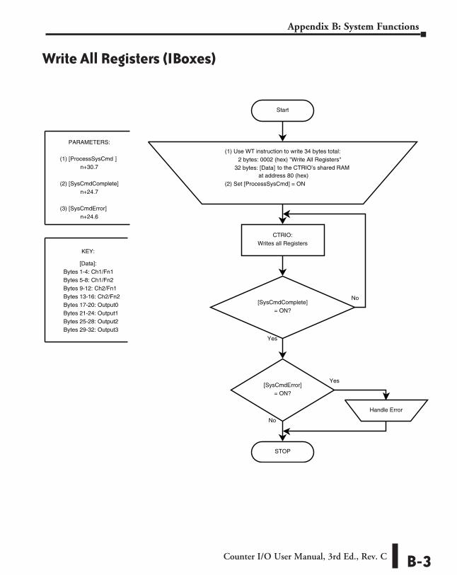
(1) [ProcessSysCmd ]n+30.7
(2) [SysCmdComplete]n+24.7
(3) [SysCmdError]n+24.6
[SysCmdError]= ON?
STOP
Handle Error
(1) Use WT instruction to write 34 bytes total:2 bytes: 0002 (hex) "Write All Registers"
32 bytes: [Data] to the CTRIO’s shared RAM at address 80 (hex)
(2) Set [ProcessSysCmd] = ON
CTRIO:Writes all Registers
KEY:
[Data]:Bytes 1-4: Ch1/Fn1Bytes 5-8: Ch1/Fn2Bytes 9-12: Ch2/Fn1Bytes 13-16: Ch2/Fn2Bytes 17-20: Output0Bytes 21-24: Output1Bytes 25-28: Output2Bytes 29-32: Output3
Write All Registers (IBoxes)
Counter I/O User Manual, 3rd Ed., Rev. C B-3
Appendix B: System Functions
Start
System Function(Write All Registers)
(DL-PLC)
Yes
No
[SysCmdComplete]= ON?
Yes
No
PARAMETERS:
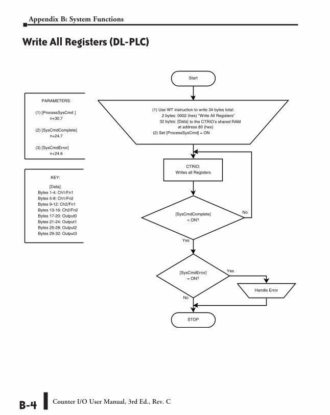
(1) [ProcessSysCmd ]n+30.7
(2) [SysCmdComplete]n+24.7
(3) [SysCmdError]n+24.6
[SysCmdError]= ON?
STOP
Handle Error
(1) Use WT instruction to write 34 bytes total:2 bytes: 0002 (hex) "Write All Registers"
32 bytes: [Data] to the CTRIO’s shared RAM at address 80 (hex)
(2) Set [ProcessSysCmd] = ON
CTRIO:Writes all Registers
KEY:
[Data]:Bytes 1-4: Ch1/Fn1Bytes 5-8: Ch1/Fn2Bytes 9-12: Ch2/Fn1Bytes 13-16: Ch2/Fn2Bytes 17-20: Output0Bytes 21-24: Output1Bytes 25-28: Output2Bytes 29-32: Output3
Write All Registers (DL-PLC)
Counter I/O User Manual, 3rd Ed., Rev. CB-4
Appendix B: System Functions
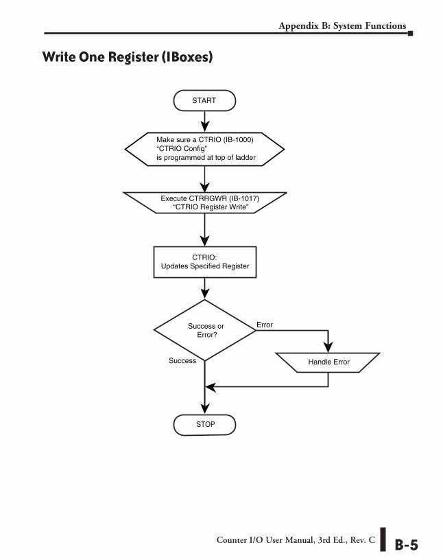
CTRIO:Updates Specified Register
Execute CTRRGWR (IB-1017)“CTRIO Register Write”
ErrorSuccess orError?
STOP
START
System Function(Write One Register)
(IBoxes)
is programmed at top of ladder
Make sure a CTRIO (IB-1000)“CTRIO Config”
Success Handle Error
Write One Register (IBoxes)
Counter I/O User Manual, 3rd Ed., Rev. C B-5
Appendix B: System Functions
Start
System Function(Write One Register)
(DL-PLC)
Yes
No
[SysCmdComplete]= ON?
Yes
No
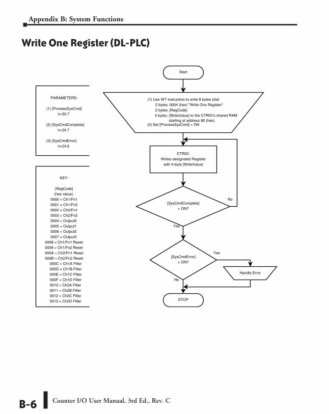
PARAMETERS:
(1) [ProcessSysCmd]n+30.7
(2) [SysCmdComplete]n+24.7
(3) [SysCmdError]n+24.6
[SysCmdError]= ON?
STOP
Handle Error
(1) Use WT instruction to write 8 bytes total2 bytes: 0004 (hex) "Write One Register"2 bytes: [RegCode]4 bytes: [WriteValue] to the CTRIO’s shared RAM
starting at address 80 (hex)(2) Set [ProcessSysCmd] = ON
CTRIO:Writes designated Register
with 4-byte [WriteValue]
KEY:
[RegCode](hex value):
0000 = Ch1/Fn10001 = Ch1/Fn20002 = Ch2/Fn10003 = Ch2/Fn20004 = Output00005 = Output10006 = Output20007 = Output3
0008 = Ch1/Fn1 Reset0009 = Ch1/Fn2 Reset000A = Ch2/Fn1 Reset000B = Ch2/Fn2 Reset
000C = Ch1A Filter000D = Ch1B Filter000E = Ch1C Filter000F = Ch1D Filter0010 = Ch2A Filter0011 = Ch2B Filter0012 = Ch2C Filter0013 = Ch2D Filter
Write One Register (DL-PLC)
Counter I/O User Manual, 3rd Ed., Rev. CB-6
Appendix B: System Functions
Start
System Function(Read All Registers)
(IBoxes)
Yes
No
[SysCmdComplete]= ON?
Yes
No
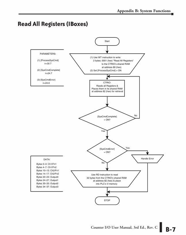
PARAMETERS:
(1) [ProcessSysCmd]n+30.7
(2) [SysCmdComplete]n+24.7
(3) [SysCmdError]n+24.6
[SysCmdError]= ON?
STOP
Handle Error
(1) Use WT instruction to write 2 bytes: 0001 (hex) "Read All Registers"
to the CTRIO’s shared RAM at address 80 (hex)
(2) Set [ProcessSysCmd] = ON
CTRIO:Reads all Registers &
Places them in its shared RAMat address 82 (hex) for retrieval
DATA:
Bytes 0–3: Ch1/Fn1Bytes 4–7: Ch1/Fn2Bytes 10–13: Ch2/Fn1Bytes 14–17: Ch2/Fn2Bytes 20–23: Output0Bytes 24–27: Output1Bytes 30–33: Output2Bytes 34–37: Output3
Use RD instruction to read 32 bytes from the CTRIO’s shared RAM
at address 82 (hex) & placeinto PLC’s V-memory
Read All Registers (IBoxes)
Counter I/O User Manual, 3rd Ed., Rev. C B-7
Appendix B: System Functions
Start
System Function(Read All Registers)
(DL-PLC)
Yes
No
[SysCmdComplete]= ON?
Yes
No
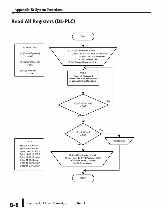
PARAMETERS:
(1) [ProcessSysCmd ]n+30.7
(2) [SysCmdComplete]n+24.7
(3) [SysCmdError]n+24.6
[SysCmdError]= ON?
STOP
Handle Error
(1) Use WT instruction to write 2 bytes: 0001 (hex) "Read All Registers"
to the CTRIO’s shared RAM at address 80 (hex)
(2) Set [ProcessSysCmd] = ON
CTRIO:Reads all Registers &
Places them in its shared RAMat address 82 (hex) for retrival
DATA:
Bytes 0–1: Ch1/Fn1Bytes 4–7: Ch1/Fn2Bytes 10–13: Ch2/Fn1Bytes 14–17: Ch2/Fn2Bytes 20–23: Output0Bytes 24–27: Output1Bytes 30–33: Output2Bytes 34–37: Output3
(1) Use RD instruction to read 32 bytes from the CTRIO’s shared RAM
at address 82 (hex) & placeinto PLC’s V-memory
Read All Registers (DL-PLC)
Counter I/O User Manual, 3rd Ed., Rev. CB-8
Appendix B: System Functions
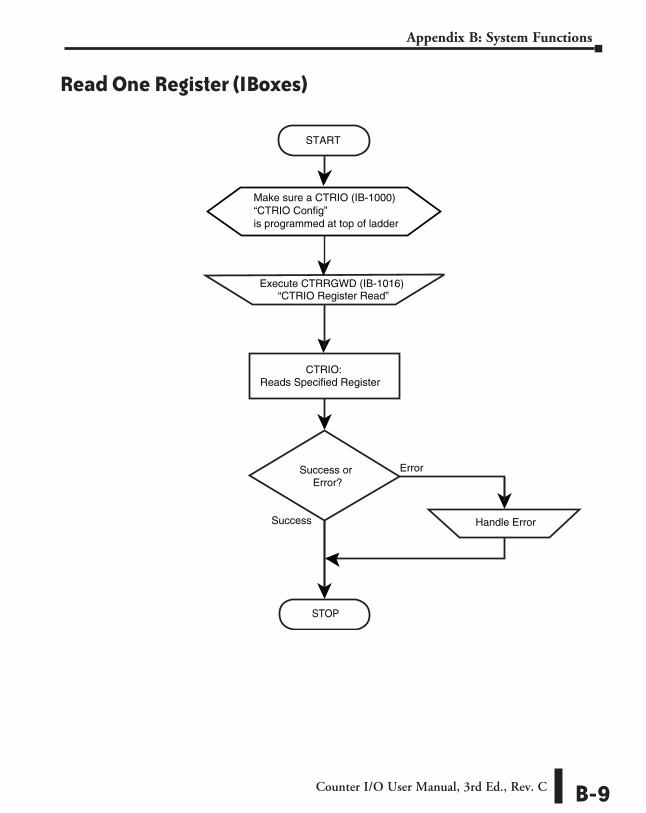
CTRIO:Reads Specified Register
Execute CTRRGWD (IB-1016)“CTRIO Register Read”
ErrorSuccess orError?
STOP
START
System Function(Read One Register)
(IBoxes)
is programmed at top of ladder
Make sure a CTRIO (IB-1000)“CTRIO Config”
Success Handle Error
Read One Register (IBoxes)
Counter I/O User Manual, 3rd Ed., Rev. C B-9
Appendix B: System Functions
Start
System Function(Read One Register)
(DL-PLC)
Yes
No
[SysCmdComplete]= ON?
Yes
No
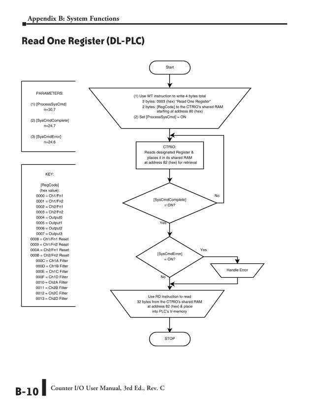
PARAMETERS:
(1) [ProcessSysCmd]n+30.7
(2) [SysCmdComplete]n+24.7
(3) [SysCmdError]n+24.6
[SysCmdError]= ON?
STOP
Handle Error
(1) Use WT instruction to write 4 bytes total2 bytes: 0003 (hex) “Read One Register"2 bytes: [RegCode] to the CTRIO’s shared RAM
starting at address 80 (hex)
(2) Set [ProcessSysCmd] = ON
CTRIO:Reads designated Register &
places it in its shared RAMat address 82 (hex) for retrieval
KEY:
[RegCode](hex value):
0000 = Ch1/Fn10001 = Ch1/Fn20002 = Ch2/Fn10003 = Ch2/Fn20004 = Output00005 = Output10006 = Output20007 = Output3
0008 = Ch1/Fn1 Reset0009 = Ch1/Fn2 Reset000A = Ch2/Fn1 Reset000B = Ch2/Fn2 Reset
000C = Ch1A Filter000D = Ch1B Filter000E = Ch1C Filter000F = Ch1D Filter0010 = Ch2A Filter0011 = Ch2B Filter0012 = Ch2C Filter0013 = Ch2D Filter Use RD instruction to read
32 bytes from the CTRIO’s shared RAM at address 82 (hex) & place
into PLC’s V-memory
Read One Register (DL-PLC)
Counter I/O User Manual, 3rd Ed., Rev. CB-10
Appendix B: System Functions
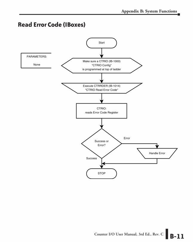
Start
System Function(Read Error Code)
(IBoxes)
CTRIO:reads Error Code Register
Make sure a CTRIO (IB-1000)"CTRIO Config"
is programmed at top of ladder
Execute CTRRDER (IB-1014)"CTRIO Read Error Code"
Error
Success
Success orError?
STOP
Handle Error
PARAMETERS:
None
Read Error Code (IBoxes)
Counter I/O User Manual, 3rd Ed., Rev. C B-11
Appendix B: System Functions
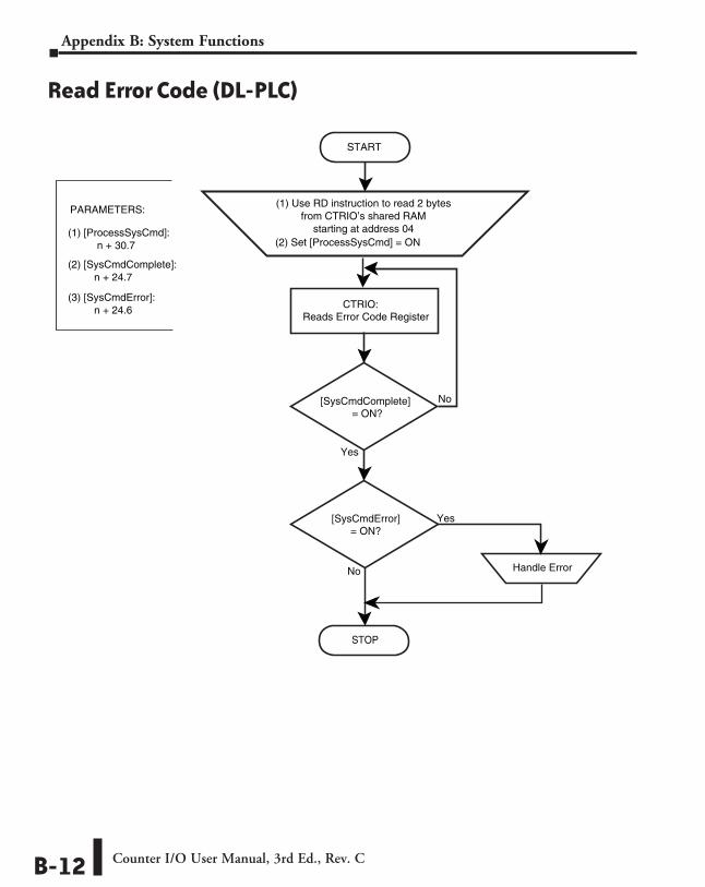
START
(Read Error Code)(DL-PLC)
STOP
starting at address 04
(1) Use RD instruction to read 2 bytesfrom CTRIO’s shared RAM
PARAMETERS:
(1) [ProcessSysCmd]: n + 30.7
(2) [SysCmdComplete]:n + 24.7
(3) [SysCmdError]:n + 24.6
Yes
No
No
Yes
Handle Error
[SysCmdComplete]= ON?
CTRIO:Reads Error Code Register
[SysCmdError]= ON?
(2) Set [ProcessSysCmd] = ON
System Function
Read Error Code (DL-PLC)
Counter I/O User Manual, 3rd Ed., Rev. CB-12
Appendix B: System Functions
System Functions Examples Overview
NOTE: System Functions are supported only when the CTRIO module is installed in the same base as the DirectLOGIC CPU.
The Systems Functions examples on the following pages use the DirectLOGIC Write to Intelligent Module (WT) and/or Read from Intelligent Module (RD) instructions to write to or read from the CTRIO’s internal registers.
Reading From CTRIO Internal MemoryReading the CTRIO’s internal memory consists of several steps. Step one is using the WT instruction to send a Systems Function’s command to the CTRIO telling it to put its internal register values into the CTRIO’s “shared RAM”. Step two is processing the request for the internal register values using the Process Command bit. Step three is using the RD instruction to read the values from the CTRIO’s “shared RAM” memory into PLC V-memory.
Steps 1 and 2: WT instruction and Process Command PLC V-memory ==> CTRIO’s Shared RAM
CTRIO’s Shared RAM ==> Process Command to internal processor CTRIO’s Shared RAM <== Internal data values
Step 3: RD instruction PLC V-memory <== CTRIO’s Shared RAM
Writing to CTRIO Internal Memory Writing to the CTRIO’s internal registers is basically a two step process. Step one is using the WT instruction to send a System Function command and the desired data values to the CTRIO’s “Shared RAM”. Step two is using the Process Command bit to tell the CTRIO to process the command and data values that are in the CTRIO’s Shared RAM. This moves the data values from the Shared RAM into the CTRIO’s internal registers.
Steps 1 and 2: WT instruction (command and data) and Process Command Bit: PLC V-memory ==> CTRIO Shared RAM
CTRIO Shared RAM ==> Process Command to internal processor CTRIO Shared RAM ==> internal data registers
NOTE: This function is not available when the CTRIO module is installed in an EBC expansion base.
Counter I/O User Manual, 3rd Ed., Rev. C B-13
Appendix B: System Functions
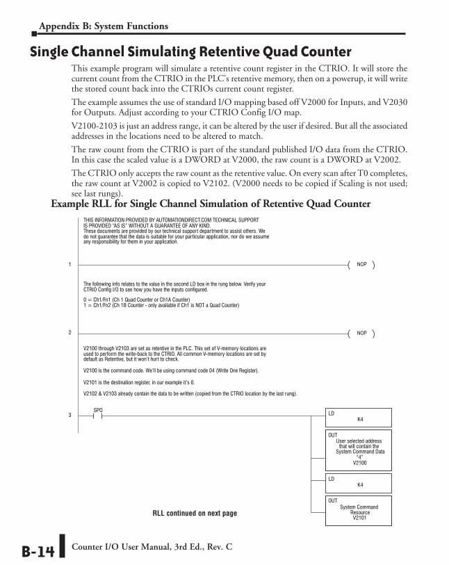
Single Channel Simulating Retentive Quad Counter This example program will simulate a retentive count register in the CTRIO. It will store the current count from the CTRIO in the PLC's retentive memory, then on a powerup, it will write the stored count back into the CTRIOs current count register.
The example assumes the use of standard I/O mapping based off V2000 for Inputs, and V2030 for Outputs. Adjust according to your CTRIO Config I/O map.
V2100-2103 is just an address range, it can be altered by the user if desired. But all the associated addresses in the locations need to be altered to match.
The raw count from the CTRIO is part of the standard published I/O data from the CTRIO. In this case the scaled value is a DWORD at V2000, the raw count is a DWORD at V2002.
The CTRIO only accepts the raw count as the retentive value. On every scan after T0 completes, the raw count at V2002 is copied to V2102. (V2000 needs to be copied if Scaling is not used; see last rungs).
NOP
NOP
NOP
SET
END
RST
LDK4
LDK4
LDK8
LDK2
LDK80
LDD
OUTD
V2000
V2102
TMRFE/RT0K5
SPO
SPO
SP1
SP1
SP1 T0
T0
T0
C1000
B2024.7
C1000
B2024.6
System Command Data
OUTD
V2102System Command Data
LDD
V2002System Command Data
V2100
V2101
OUT
OUT
“4”System Command Data
User selected addressthat will contain the
V2100 through V2103 are set as retentive in the PLC. This set of V-memory locations are
V2100 is the command code. We’ll be using command code 04 (Write One Register).
V2101 is the destination register, in our example it’s 0.
V2102 & V2103 already contain the data to be written (copied from the CTRIO location by the last rung).
V2100
B2060.7
B2060.7
WT
“4”SysCmdCod value of
User selected addressthat will contain the
Process SystemCommand
Process SystemCommand
System CommandResource
used to perform the write-back to the CTRIO. All common V-memory locations are set by
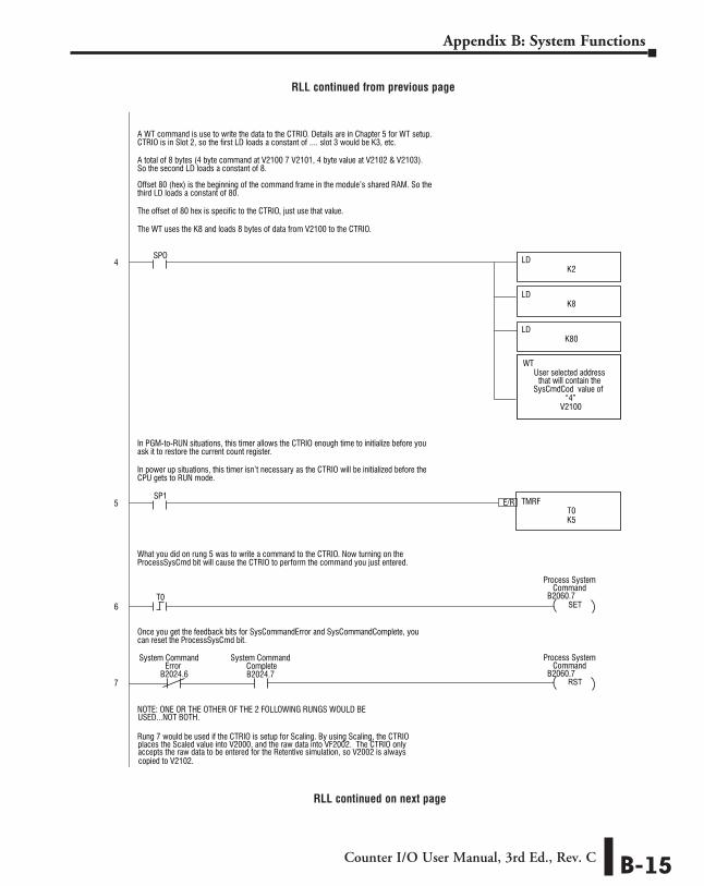
A WT command is use to write the data to the CTRIO. Details are in Chapter 5 for WT setup.CTRIO is in Slot 2, so the first LD loads a constant of .... slot 3 would be K3, etc.
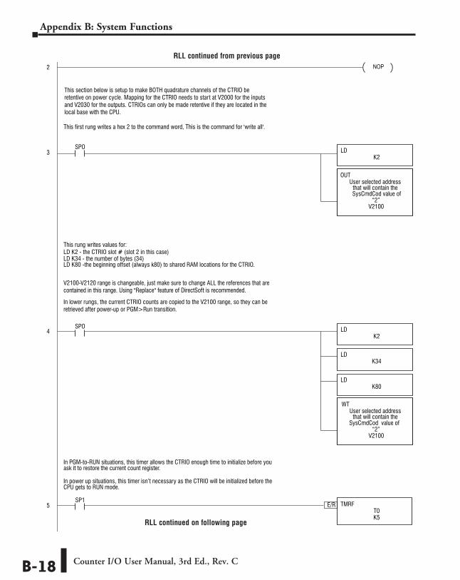
In PGM-to-RUN situations, this timer allows the CTRIO enough time to initialize before you ask it to restore the current count register.
What you did on rung 5 was to write a command to the CTRIO. Now turning on the ProcessSysCmd bit will cause the CTRIO to perform the command you just entered.
Once you get the feedback bits for SysCommandError and SysCommandComplete, youcan reset the ProcessSysCmd bit.
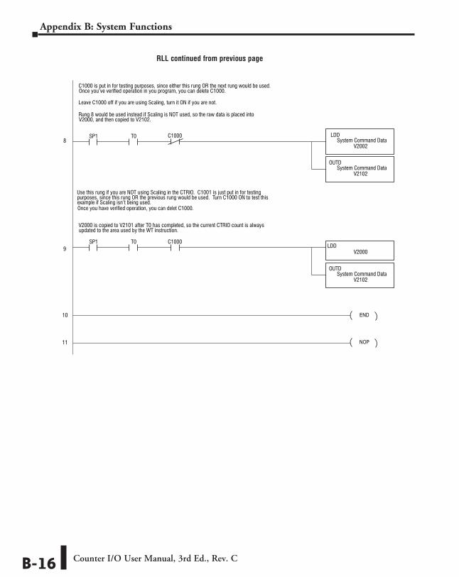
Rung 8 would be used instead if Scaling is NOT used, so the raw data is placed into
Leave C1000 off if you are using Scaling, turn it ON if you are not.
V2000, and then copied to V2102.
V2000 is copied to V2101 after T0 has completed, so the current CTRIO count is alwaysupdated to the area used by the WT instruction.
C1000 is put in for testing purposes, since either this rung OR the next rung would be used.Once you’ve verified operation in you program, you can delete C1000.
NOTE: ONE OR THE OTHER OF THE 2 FOLLOWING RUNGS WOULD BEUSED...NOT BOTH.
Rung 7 would be used if the CTRIO is setup for Scaling. By using Scaling, the CTRIO places the Scaled value into V2000, and the raw data into VF2002. The CTRIO onlyaccepts the raw data to be entered for the Retentive simulation, so V2002 is alwayscopied to V2102.
Use this rung if you are NOT using Scaling in the CTRIO. C1001 is just put in for testingpurposes, since this rung OR the previous rung would be used. Turn C1000 ON to test thisexample if Scaling isn’t being used. Once you have verified operation, you can delet C1000.
In power up situations, this timer isn’t necessary as the CTRIO will be initialized before theCPU gets to RUN mode.
A total of 8 bytes (4 byte command at V2100 7 V2101, 4 byte value at V2102 & V2103). So the second LD loads a constant of 8.
Offset 80 (hex) is the beginning of the command frame in the module’s shared RAM. So the
The offset of 80 hex is specific to the CTRIO, just use that value.
The WT uses the K8 and loads 8 bytes of data from V2100 to the CTRIO.
third LD loads a constant of 80.
The following info relates to the value in the second LD box in the rung below. Verify yourCTRIO Config I/O to see how you have the inputs configured.
These documents are provided by our technical support department to assist others. We
THIS INFORMATION PROVIDED BY AUTOMATIONDIRECT.COM TECHNICAL SUPPORTIS PROVIDED “AS IS” WITHOUT A GUARANTEE OF ANY KIND.
do not guarantee that the data is suitable for your particular application, nor do we assume any responsibility for them in your application.
0 = Ch1/Fn1 (Ch 1 Quad Counter or Ch1A Counter)1 = Ch1/Fn2 (Ch 1B Counter - only available if Ch1 is NOT a Quad Counter)
default as Retentive, but it won’t hurt to check.
1
2
3
4
5
6
7
8
9
10
11
System Command System CommandCompleteError
RLL continued on next page
Example RLL for Single Channel Simulation of Retentive Quad Counter
Counter I/O User Manual, 3rd Ed., Rev. CB-14
Appendix B: System Functions
NOP
NOP
NOP
SET
END
RST
LDK4
LDK4
LDK8
LDK2
LDK80
LDD
OUTD
V2000
V2102
TMRFE/RT0K5
SPO
SPO
SP1
SP1
SP1 T0
T0
T0
C1000
B2024.7
C1000
B2024.6
System Command Data
OUTD
V2102System Command Data
LDD
V2002System Command Data
V2100
V2101
OUT
OUT
“4”System Command Data
User selected addressthat will contain the
V2100 through V2103 are set as retentive in the PLC. This set of V-memory locations are
V2100 is the command code. We’ll be using command code 04 (Write One Register).
V2101 is the destination register, in our example it’s 0.
V2102 & V2103 already contain the data to be written (copied from the CTRIO location by the last rung).
V2100
B2060.7
B2060.7
WT
“4”SysCmdCod value of
User selected addressthat will contain the
Process SystemCommand
Process SystemCommand
System CommandResource
used to perform the write-back to the CTRIO. All common V-memory locations are set by
A WT command is use to write the data to the CTRIO. Details are in Chapter 5 for WT setup.CTRIO is in Slot 2, so the first LD loads a constant of .... slot 3 would be K3, etc.
In PGM-to-RUN situations, this timer allows the CTRIO enough time to initialize before you ask it to restore the current count register.
What you did on rung 5 was to write a command to the CTRIO. Now turning on the ProcessSysCmd bit will cause the CTRIO to perform the command you just entered.
Once you get the feedback bits for SysCommandError and SysCommandComplete, youcan reset the ProcessSysCmd bit.
Rung 8 would be used instead if Scaling is NOT used, so the raw data is placed into
Leave C1000 off if you are using Scaling, turn it ON if you are not.
V2000, and then copied to V2102.
V2000 is copied to V2101 after T0 has completed, so the current CTRIO count is alwaysupdated to the area used by the WT instruction.
C1000 is put in for testing purposes, since either this rung OR the next rung would be used.Once you’ve verified operation in you program, you can delete C1000.
NOTE: ONE OR THE OTHER OF THE 2 FOLLOWING RUNGS WOULD BEUSED...NOT BOTH.
Rung 7 would be used if the CTRIO is setup for Scaling. By using Scaling, the CTRIO places the Scaled value into V2000, and the raw data into VF2002. The CTRIO onlyaccepts the raw data to be entered for the Retentive simulation, so V2002 is alwayscopied to V2102.
Use this rung if you are NOT using Scaling in the CTRIO. C1001 is just put in for testingpurposes, since this rung OR the previous rung would be used. Turn C1000 ON to test thisexample if Scaling isn’t being used. Once you have verified operation, you can delet C1000.
In power up situations, this timer isn’t necessary as the CTRIO will be initialized before theCPU gets to RUN mode.
A total of 8 bytes (4 byte command at V2100 7 V2101, 4 byte value at V2102 & V2103). So the second LD loads a constant of 8.
Offset 80 (hex) is the beginning of the command frame in the module’s shared RAM. So the
The offset of 80 hex is specific to the CTRIO, just use that value.
The WT uses the K8 and loads 8 bytes of data from V2100 to the CTRIO.
third LD loads a constant of 80.
The following info relates to the value in the second LD box in the rung below. Verify yourCTRIO Config I/O to see how you have the inputs configured.
These documents are provided by our technical support department to assist others. We
THIS INFORMATION PROVIDED BY AUTOMATIONDIRECT.COM TECHNICAL SUPPORTIS PROVIDED “AS IS” WITHOUT A GUARANTEE OF ANY KIND.
do not guarantee that the data is suitable for your particular application, nor do we assume any responsibility for them in your application.
0 = Ch1/Fn1 (Ch 1 Quad Counter or Ch1A Counter)1 = Ch1/Fn2 (Ch 1B Counter - only available if Ch1 is NOT a Quad Counter)
default as Retentive, but it won’t hurt to check.
1
2
3
4
5
6
7
8
9
10
11
System Command System CommandCompleteError
RLL continued on next page
RLL continued from previous page
Counter I/O User Manual, 3rd Ed., Rev. C B-15
Appendix B: System Functions
NOP
NOP
NOP
SET
END
RST
LDK4
LDK4
LDK8
LDK2
LDK80
LDD
OUTD
V2000
V2102
TMRFE/RT0K5
SPO
SPO
SP1
SP1
SP1 T0
T0
T0
C1000
B2024.7
C1000
B2024.6
System Command Data
OUTD
V2102System Command Data
LDD
V2002System Command Data
V2100
V2101
OUT
OUT
“4”System Command Data
User selected addressthat will contain the
V2100 through V2103 are set as retentive in the PLC. This set of V-memory locations are
V2100 is the command code. We’ll be using command code 04 (Write One Register).
V2101 is the destination register, in our example it’s 0.
V2102 & V2103 already contain the data to be written (copied from the CTRIO location by the last rung).
V2100
B2060.7
B2060.7
WT
“4”SysCmdCod value of
User selected addressthat will contain the
Process SystemCommand
Process SystemCommand
System CommandResource
used to perform the write-back to the CTRIO. All common V-memory locations are set by
A WT command is use to write the data to the CTRIO. Details are in Chapter 5 for WT setup.CTRIO is in Slot 2, so the first LD loads a constant of .... slot 3 would be K3, etc.
In PGM-to-RUN situations, this timer allows the CTRIO enough time to initialize before you ask it to restore the current count register.
What you did on rung 5 was to write a command to the CTRIO. Now turning on the ProcessSysCmd bit will cause the CTRIO to perform the command you just entered.
Once you get the feedback bits for SysCommandError and SysCommandComplete, youcan reset the ProcessSysCmd bit.
Rung 8 would be used instead if Scaling is NOT used, so the raw data is placed into
Leave C1000 off if you are using Scaling, turn it ON if you are not.
V2000, and then copied to V2102.
V2000 is copied to V2101 after T0 has completed, so the current CTRIO count is alwaysupdated to the area used by the WT instruction.
C1000 is put in for testing purposes, since either this rung OR the next rung would be used.Once you’ve verified operation in you program, you can delete C1000.
NOTE: ONE OR THE OTHER OF THE 2 FOLLOWING RUNGS WOULD BEUSED...NOT BOTH.
Rung 7 would be used if the CTRIO is setup for Scaling. By using Scaling, the CTRIO places the Scaled value into V2000, and the raw data into VF2002. The CTRIO onlyaccepts the raw data to be entered for the Retentive simulation, so V2002 is alwayscopied to V2102.
Use this rung if you are NOT using Scaling in the CTRIO. C1001 is just put in for testingpurposes, since this rung OR the previous rung would be used. Turn C1000 ON to test thisexample if Scaling isn’t being used. Once you have verified operation, you can delet C1000.
In power up situations, this timer isn’t necessary as the CTRIO will be initialized before theCPU gets to RUN mode.
A total of 8 bytes (4 byte command at V2100 7 V2101, 4 byte value at V2102 & V2103). So the second LD loads a constant of 8.
Offset 80 (hex) is the beginning of the command frame in the module’s shared RAM. So the
The offset of 80 hex is specific to the CTRIO, just use that value.
The WT uses the K8 and loads 8 bytes of data from V2100 to the CTRIO.
third LD loads a constant of 80.
The following info relates to the value in the second LD box in the rung below. Verify yourCTRIO Config I/O to see how you have the inputs configured.
These documents are provided by our technical support department to assist others. We
THIS INFORMATION PROVIDED BY AUTOMATIONDIRECT.COM TECHNICAL SUPPORTIS PROVIDED “AS IS” WITHOUT A GUARANTEE OF ANY KIND.
do not guarantee that the data is suitable for your particular application, nor do we assume any responsibility for them in your application.
0 = Ch1/Fn1 (Ch 1 Quad Counter or Ch1A Counter)1 = Ch1/Fn2 (Ch 1B Counter - only available if Ch1 is NOT a Quad Counter)
default as Retentive, but it won’t hurt to check.
1
2
3
4
5
6
7
8
9
10
11
System Command System CommandCompleteError
RLL continued from previous page
Counter I/O User Manual, 3rd Ed., Rev. CB-16
Appendix B: System Functions
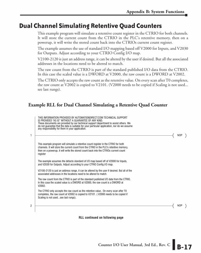
Dual Channel Simulating Retentive Quad CountersThis example program will simulate a retentive count register in the CTRIO for both channels. It will store the current count from the CTRIO in the PLC's retentive memory, then on a powerup, it will write the stored count back into the CTRIOs current count register.
The example assumes the use of standard I/O mapping based off V2000 for Inputs, and V2030 for Outputs. Adjust according to your CTRIO Config I/O map.
V2100-2120 is just an address range, it can be altered by the user if desired. But all the associated addresses in the locations need to be altered to match.
The raw count from the CTRIO is part of the standard published I/O data from the CTRIO. In this case the scaled value is a DWORD at V2000, the raw count is a DWORD at V2002.
The CTRIO only accepts the raw count as the retentive value. On every scan after T0 completes, the raw count at V2002 is copied to V2101. (V2000 needs to be copied if Scaling is not used...see last rungs).
Example RLL for Dual Channel Simulating a Retentive Quad Counter
NOP
NOP
SET
END
RST
LDK34
LDK2
LDK80
TMRFE/RT0K5
SPO
SP1
TA0 K18
T0
B2024.7B2024.6
LDD
V2012Channel 2 count
LDD
V2002Current Raw Count
OUTD
“Ch2Fn1”V2105
System Command Data
OUTD
“Ch1Fn1”V2101
System Command Data
This section below is setup to make BOTH quadrature channels of the CTRIO beretentive on power cycle. Mapping for the CTRIO needs to start at V2000 for the inputsand V2030 for the outputs. CTRIOs can only be made retentive if they are located in thelocal base with the CPU.
The CTRIO only accepts the raw count as the retentive value.. On every scan after T0completes, the raw count at V2002 is copied to V2101. ( V2000 needs to be copied ifScaling is not used...see last rungs).
This first rung writes a hex 2 to the command word, This is the command for 'write all'.
V2100
B2060.7
B2060.7
WT
“2”SysCmdCod value of
User selected addressthat will contain the
Process SystemCommand
Process SystemCommand
This rung writes values for:LD K2 - the CTRIO slot # (slot 2 in this case)
In PGM-to-RUN situations, this timer allows the CTRIO enough time to initialize before you ask it to restore the current count register.
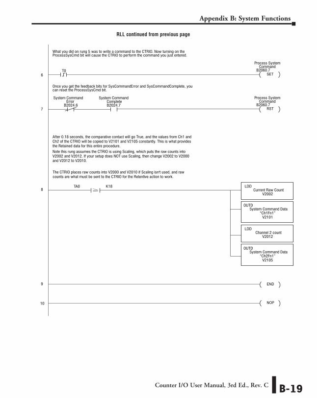
What you did on rung 5 was to write a command to the CTRIO. Now turning on the ProcessSysCmd bit will cause the CTRIO to perform the command you just entered.
Once you get the feedback bits for SysCommandError and SysCommandComplete, youcan reset the ProcessSysCmd bit.
The CTRIO places raw counts into V2000 and V2010 if Scaling isn't used, and rawcounts are what must be sent to the CTRIO for the Retentive action to work.
Note this rung assumes the CTRIO is using Scaling, which puts the raw counts intoV2002 and V2012. If your setup does NOT use Scaling, then change V2002 to V2000and V2012 to V2010.
After 0.18 seconds, the comparative contact will go True, and the values from Ch1 andCh2 of the CTRIO will be copied to V2101 and V2105 constantly. This is what providesthe Retained data for this entire procedure.
In power up situations, this timer isn’t necessary as the CTRIO will be initialized before theCPU gets to RUN mode.
LD K34 - the number of bytes (34)LD K80 -the beginning offset (always k80) to shared RAM locations for the CTRIO.
V2100-V2120 range is changeable, just make sure to change ALL the references that arecontained in this range. Using "Replace" feature of DirectSoft is recommended.
In lower rungs, the current CTRIO counts are copied to the V2100 range, so they can beretrieved after power-up or PGM>Run transition.
This example program will simulate a retentive count register in the CTRIO for bothchannels. It will store the current count from the CTRIO in the PLC's retentive memory,then on a powerup, it will write the stored count back into the CTRIOs current countregister
The example assumes the defacto standard of I/O map based off of V2000 for Inputs,and V2030 for Outputs. Adjust according to your CTRIO Config I/O map.
These documents are provided by our technical support department to assist others. We
THIS INFORMATION PROVIDED BY AUTOMATIONDIRECT.COM TECHNICAL SUPPORTIS PROVIDED “AS IS” WITHOUT A GUARANTEE OF ANY KIND.
do not guarantee that the data is suitable for your particular application, nor do we assume any responsibility for them in your application.
V2100-2120 is just an address range, it can be altered by the user if desired. But all of theassociated addresses in the locations need to be altered to match.
The raw count from the CTRIO is part of the standard published I/O data from the CTRIO.In this case the scaled value is a DWORD at V2000, the raw count is a DWORD atV2002.
NOP1
3
2
4
5
6
7
8
9
10
System Command System CommandCompleteError
LDK2
SPO
V2100
OUT
“2”SysCmdCod value of
User selected addressthat will contain the
RLL continued on following page
Counter I/O User Manual, 3rd Ed., Rev. C B-17
Appendix B: System Functions
NOP
NOP
SET
END
RST
LDK34
LDK2
LDK80
TMRFE/RT0K5
SPO
SP1
TA0 K18
T0
B2024.7B2024.6
LDD
V2012Channel 2 count
LDD
V2002Current Raw Count
OUTD
“Ch2Fn1”V2105
System Command Data
OUTD
“Ch1Fn1”V2101
System Command Data
This section below is setup to make BOTH quadrature channels of the CTRIO beretentive on power cycle. Mapping for the CTRIO needs to start at V2000 for the inputsand V2030 for the outputs. CTRIOs can only be made retentive if they are located in thelocal base with the CPU.
The CTRIO only accepts the raw count as the retentive value.. On every scan after T0completes, the raw count at V2002 is copied to V2101. ( V2000 needs to be copied ifScaling is not used...see last rungs).
This first rung writes a hex 2 to the command word, This is the command for 'write all'.
V2100
B2060.7
B2060.7
WT
“2”SysCmdCod value of
User selected addressthat will contain the
Process SystemCommand
Process SystemCommand
This rung writes values for:LD K2 - the CTRIO slot # (slot 2 in this case)
In PGM-to-RUN situations, this timer allows the CTRIO enough time to initialize before you ask it to restore the current count register.
What you did on rung 5 was to write a command to the CTRIO. Now turning on the ProcessSysCmd bit will cause the CTRIO to perform the command you just entered.
Once you get the feedback bits for SysCommandError and SysCommandComplete, youcan reset the ProcessSysCmd bit.
The CTRIO places raw counts into V2000 and V2010 if Scaling isn't used, and rawcounts are what must be sent to the CTRIO for the Retentive action to work.
Note this rung assumes the CTRIO is using Scaling, which puts the raw counts intoV2002 and V2012. If your setup does NOT use Scaling, then change V2002 to V2000and V2012 to V2010.
After 0.18 seconds, the comparative contact will go True, and the values from Ch1 andCh2 of the CTRIO will be copied to V2101 and V2105 constantly. This is what providesthe Retained data for this entire procedure.
In power up situations, this timer isn’t necessary as the CTRIO will be initialized before theCPU gets to RUN mode.
LD K34 - the number of bytes (34)LD K80 -the beginning offset (always k80) to shared RAM locations for the CTRIO.
V2100-V2120 range is changeable, just make sure to change ALL the references that arecontained in this range. Using "Replace" feature of DirectSoft is recommended.
In lower rungs, the current CTRIO counts are copied to the V2100 range, so they can beretrieved after power-up or PGM>Run transition.
This example program will simulate a retentive count register in the CTRIO for bothchannels. It will store the current count from the CTRIO in the PLC's retentive memory,then on a powerup, it will write the stored count back into the CTRIOs current countregister
The example assumes the defacto standard of I/O map based off of V2000 for Inputs,and V2030 for Outputs. Adjust according to your CTRIO Config I/O map.
These documents are provided by our technical support department to assist others. We
THIS INFORMATION PROVIDED BY AUTOMATIONDIRECT.COM TECHNICAL SUPPORTIS PROVIDED “AS IS” WITHOUT A GUARANTEE OF ANY KIND.
do not guarantee that the data is suitable for your particular application, nor do we assume any responsibility for them in your application.
V2100-2120 is just an address range, it can be altered by the user if desired. But all of theassociated addresses in the locations need to be altered to match.
The raw count from the CTRIO is part of the standard published I/O data from the CTRIO.In this case the scaled value is a DWORD at V2000, the raw count is a DWORD atV2002.
NOP1
3
2
4
5
6
7
8
9
10
System Command System CommandCompleteError
LDK2
SPO
V2100
OUT
“2”SysCmdCod value of
User selected addressthat will contain the
RLL continued on following page
RLL continued from previous page
Counter I/O User Manual, 3rd Ed., Rev. CB-18
Appendix B: System Functions
NOP
NOP
SET
END
RST
LDK34
LDK2
LDK80
TMRFE/RT0K5
SPO
SP1
TA0 K18
T0
B2024.7B2024.6
LDD
V2012Channel 2 count
LDD
V2002Current Raw Count
OUTD
“Ch2Fn1”V2105
System Command Data
OUTD
“Ch1Fn1”V2101
System Command Data
This section below is setup to make BOTH quadrature channels of the CTRIO beretentive on power cycle. Mapping for the CTRIO needs to start at V2000 for the inputsand V2030 for the outputs. CTRIOs can only be made retentive if they are located in thelocal base with the CPU.
The CTRIO only accepts the raw count as the retentive value.. On every scan after T0completes, the raw count at V2002 is copied to V2101. ( V2000 needs to be copied ifScaling is not used...see last rungs).
This first rung writes a hex 2 to the command word, This is the command for 'write all'.
V2100
B2060.7
B2060.7
WT
“2”SysCmdCod value of
User selected addressthat will contain the
Process SystemCommand
Process SystemCommand
This rung writes values for:LD K2 - the CTRIO slot # (slot 2 in this case)
In PGM-to-RUN situations, this timer allows the CTRIO enough time to initialize before you ask it to restore the current count register.
What you did on rung 5 was to write a command to the CTRIO. Now turning on the ProcessSysCmd bit will cause the CTRIO to perform the command you just entered.
Once you get the feedback bits for SysCommandError and SysCommandComplete, youcan reset the ProcessSysCmd bit.
The CTRIO places raw counts into V2000 and V2010 if Scaling isn't used, and rawcounts are what must be sent to the CTRIO for the Retentive action to work.
Note this rung assumes the CTRIO is using Scaling, which puts the raw counts intoV2002 and V2012. If your setup does NOT use Scaling, then change V2002 to V2000and V2012 to V2010.
After 0.18 seconds, the comparative contact will go True, and the values from Ch1 andCh2 of the CTRIO will be copied to V2101 and V2105 constantly. This is what providesthe Retained data for this entire procedure.
In power up situations, this timer isn’t necessary as the CTRIO will be initialized before theCPU gets to RUN mode.
LD K34 - the number of bytes (34)LD K80 -the beginning offset (always k80) to shared RAM locations for the CTRIO.
V2100-V2120 range is changeable, just make sure to change ALL the references that arecontained in this range. Using "Replace" feature of DirectSoft is recommended.
In lower rungs, the current CTRIO counts are copied to the V2100 range, so they can beretrieved after power-up or PGM>Run transition.
This example program will simulate a retentive count register in the CTRIO for bothchannels. It will store the current count from the CTRIO in the PLC's retentive memory,then on a powerup, it will write the stored count back into the CTRIOs current countregister
The example assumes the defacto standard of I/O map based off of V2000 for Inputs,and V2030 for Outputs. Adjust according to your CTRIO Config I/O map.
These documents are provided by our technical support department to assist others. We
THIS INFORMATION PROVIDED BY AUTOMATIONDIRECT.COM TECHNICAL SUPPORTIS PROVIDED “AS IS” WITHOUT A GUARANTEE OF ANY KIND.
do not guarantee that the data is suitable for your particular application, nor do we assume any responsibility for them in your application.
V2100-2120 is just an address range, it can be altered by the user if desired. But all of theassociated addresses in the locations need to be altered to match.
The raw count from the CTRIO is part of the standard published I/O data from the CTRIO.In this case the scaled value is a DWORD at V2000, the raw count is a DWORD atV2002.
NOP1
3
2
4
5
6
7
8
9
10
System Command System CommandCompleteError
LDK2
SPO
V2100
OUT
“2”SysCmdCod value of
User selected addressthat will contain the
RLL continued from previous page
Counter I/O User Manual, 3rd Ed., Rev. C B-19
Appendix B: System Functions
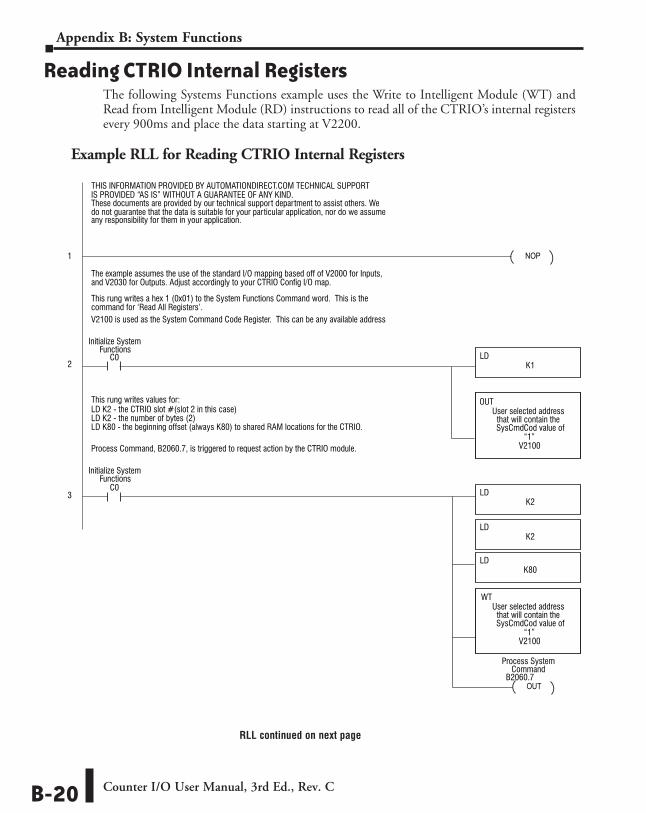
Reading CTRIO Internal RegistersThe following Systems Functions example uses the Write to Intelligent Module (WT) and Read from Intelligent Module (RD) instructions to read all of the CTRIO’s internal registers every 900ms and place the data starting at V2200.
Example RLL for Reading CTRIO Internal Registers
NOP
SET
END
LDK2
LDK2
LDK80
LDK1
LDK32
LDK2
LDK82
TMRE/RT0K9
C0
C0
C0
T0
This rung writes values for:
LD K80 - the beginning offset (always K80) to shared RAM locations for the CTRIO.
V2100 is used as the System Command Code Register. This can be any available address
Process Command, B2060.7, is triggered to request action by the CTRIO module.
V2200
C0
WT
Initialize SystemFunctions
OUTB2060.7
RSTC0
Process SystemCommand
Initialize SystemFunctions
LD K2 - the CTRIO slot #(slot 2 in this case)
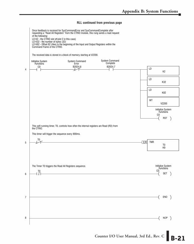
Once feedback is received for SysCommandError and SysCommandComplete afterrequesting a “Read All Registers” from the CTRIO module, this rung sends a read request
This self-running timer, T0, controls how often the internal registers are Read (RD) fromthe CTRIO.
The Timer T0 triggers the Read All Registers sequence.
This timer will trigger the sequence every 900ms.
of the following:
The received data is stored in a block of memory starting at V2200.
Command Frame of the CTRIO.
The example assumes the use of the standard I/O mapping based off of V2000 for Inputs, and V2030 for Outputs. Adjust accordingly to your CTRIO Config I/O map.
These documents are provided by our technical support department to assist others. We
THIS INFORMATION PROVIDED BY AUTOMATIONDIRECT.COM TECHNICAL SUPPORTIS PROVIDED “AS IS” WITHOUT A GUARANTEE OF ANY KIND.
do not guarantee that the data is suitable for your particular application, nor do we assume any responsibility for them in your application.
This rung writes a hex 1 (0x01) to the System Functions Command word. This is thecommand for ‘Read All Registers’.
LD K2 - the number of bytes (2)
LD K82 - Offset 82 (Hex) is the beginning of the Input and Output Registers within the
LD K2 - the CTRIO slot #(slot 2 in this case)LD K32 - the number of bytes (32)
1
2
3
4
5
6
7
8
System CommandComplete
System CommandError
Initialize SystemFunctions
Initialize SystemFunctions
Initialize SystemFunctions
V2100
WT
“1”SysCmdCod value of
User selected addressthat will contain the
V2100
OUT
“1”SysCmdCod value of
User selected addressthat will contain the
B2024.7B2024.6
T0
NOP
RLL continued on next page
Counter I/O User Manual, 3rd Ed., Rev. CB-20
Appendix B: System Functions
RLL continued from previous page
NOP
SET
END
LDK2
LDK2
LDK80
LDK1
LDK32
LDK2
LDK82
TMRE/RT0K9
C0
C0
C0
T0
This rung writes values for:
LD K80 - the beginning offset (always K80) to shared RAM locations for the CTRIO.
V2100 is used as the System Command Code Register. This can be any available address
Process Command, B2060.7, is triggered to request action by the CTRIO module.
V2200
C0
WT
Initialize SystemFunctions
OUTB2060.7
RSTC0
Process SystemCommand
Initialize SystemFunctions
LD K2 - the CTRIO slot #(slot 2 in this case)
Once feedback is received for SysCommandError and SysCommandComplete afterrequesting a “Read All Registers” from the CTRIO module, this rung sends a read request
This self-running timer, T0, controls how often the internal registers are Read (RD) fromthe CTRIO.
The Timer T0 triggers the Read All Registers sequence.
This timer will trigger the sequence every 900ms.
of the following:
The received data is stored in a block of memory starting at V2200.
Command Frame of the CTRIO.
The example assumes the use of the standard I/O mapping based off of V2000 for Inputs, and V2030 for Outputs. Adjust accordingly to your CTRIO Config I/O map.
These documents are provided by our technical support department to assist others. We
THIS INFORMATION PROVIDED BY AUTOMATIONDIRECT.COM TECHNICAL SUPPORTIS PROVIDED “AS IS” WITHOUT A GUARANTEE OF ANY KIND.
do not guarantee that the data is suitable for your particular application, nor do we assume any responsibility for them in your application.
This rung writes a hex 1 (0x01) to the System Functions Command word. This is thecommand for ‘Read All Registers’.
LD K2 - the number of bytes (2)
LD K82 - Offset 82 (Hex) is the beginning of the Input and Output Registers within the
LD K2 - the CTRIO slot #(slot 2 in this case)LD K32 - the number of bytes (32)
1
2
3
4
5
6
7
8
System CommandComplete
System CommandError
Initialize SystemFunctions
Initialize SystemFunctions
Initialize SystemFunctions
V2100
WT
“1”SysCmdCod value of
User selected addressthat will contain the
V2100
OUT
“1”SysCmdCod value of
User selected addressthat will contain the
B2024.7B2024.6
T0
NOP
Counter I/O User Manual, 3rd Ed., Rev. C B-21
Appendix B: System Functions