In System Programmer - Microchip...
20
www.rovingnetworks.com 1 RN-WIFLYCR-UM-.01 RN-ISP-UM In-System Programmer USER MANUAL © 2012 Roving Networks. All rights reserved. RN-ISP-UM-1.1 Version 1.1 1/19/2012
Transcript of In System Programmer - Microchip...
www.rovingnetworks.com 1
RN-WIFLYCR-UM-.01
RN-ISP-UM
In-System Programmer
USER MANUAL © 2012 Roving Networks. All rights reserved.
RN-ISP-UM-1.1 Version 1.1 1/19/2012
www.rovingnetworks.com 2
RN-ISP-UM-1.1
OVERVIEW
You use Roving Networks In-System-Programmer (ISP), RN-ISP, to download code to WiFly modules and debug it. The
ISP can download code to the WiFly evaluation boards if they have a 16 or 10-pin debug header. The ISP measures
current consumption and plots the power profiles of the WiFly modules in different power states. It also exposes the
hardware signals and certain GPIO pins for debugging. The ISP has reset and wake buttons that help with debugging
applications.
The RN-ISP is part of the RN-SDK, which consists of:
• RN-IDK—This board contains the WiFly module, dual power supplies, multiple hardware interfaces (e.g., UART,
SDIO/SPI slave, and SPI master), and current measurement capability that allows power profiling of the WiFly
module.
• RN-ISP—The ISP provides a means to download and debug application code to the WiFly module.
• USB cable—This cable connects the RN-ISP to a Linux-based development computer’s USB port.
• 16-way ribbon cable—This cable provides data and power connections between the RN-ISP and the RN-IDK.
PREREQUISITES
Before using the RN-ISP, you must have the following hardware and software:
• Development PC with Linux and a USB port.
• Configuration permissions for the development PC. Developers should have an account on the development PC
with either sudo (if using Ubuntu) or root access.
• RN-SDK hardware.
• Jira access to software tools and libraries for developing applications on the WiFly module.
NOTE: The development environment is Linux. You cannot development firmware in the Windows or Mac
environments.
www.rovingnetworks.com 3
RN-ISP-UM-1.1
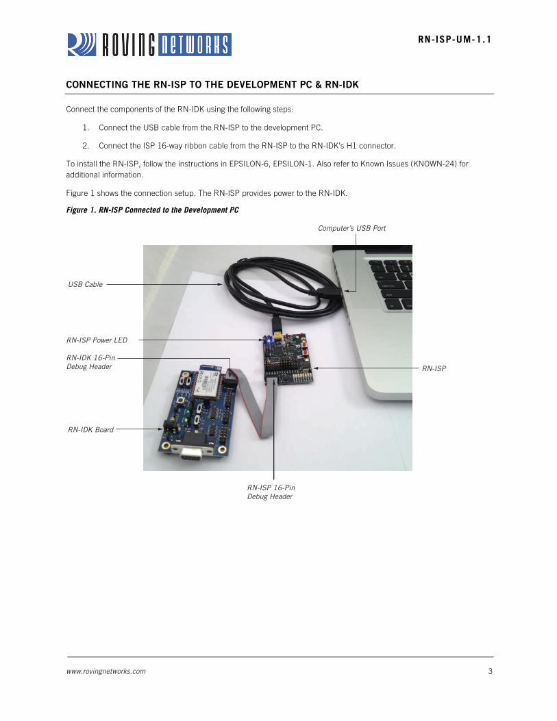
CONNECTING THE RN-ISP TO THE DEVELOPMENT PC & RN-IDK
Connect the components of the RN-IDK using the following steps:
1. Connect the USB cable from the RN-ISP to the development PC.
2. Connect the ISP 16-way ribbon cable from the RN-ISP to the RN-IDK’s H1 connector.
To install the RN-ISP, follow the instructions in EPSILON-6, EPSILON-1. Also refer to Known Issues (KNOWN-24) for
additional information.
Figure 1 shows the connection setup. The RN-ISP provides power to the RN-IDK.
Figure 1. RN-ISP Connected to the Development PC
USB Cable
RN-ISP Power LED
RN-ISP 16-Pin Debug Header
RN-ISPRN-IDK 16-PinDebug Header
RN-IDK Board
Computer’s USB Port
www.rovingnetworks.com 4
RN-ISP-UM-1.1
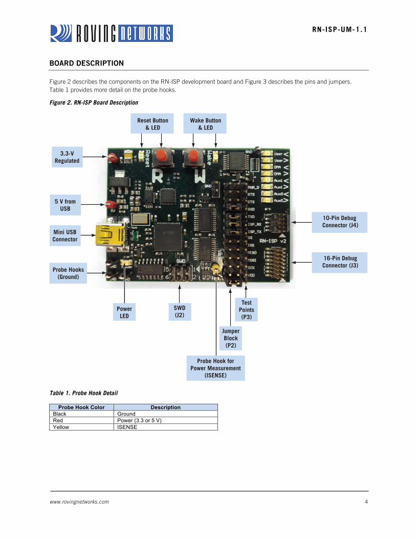
BOARD DESCRIPTION
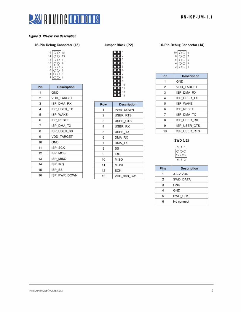
Figure 2 describes the components on the RN-ISP development board and Figure 3 describes the pins and jumpers.
Table 1 provides more detail on the probe hooks.
Figure 2. RN-ISP Board Description
Table 1. Probe Hook Detail
Probe Hook Color Description Black Ground Red Power (3.3 or 5 V) Yellow ISENSE
Reset Button& LED
SWD(J2)
3.3-VRegulated
16-Pin DebugConnector (J3)
10-Pin Debug Connector (J4)
Wake Button& LED
5 V fromUSB
Mini USBConnector
Probe Hooks(Ground)
Probe Hook forPower Measurement
(ISENSE)
PowerLED
JumperBlock(P2)
TestPoints(P3)
www.rovingnetworks.com 5
RN-ISP-UM-1.1
Figure 3. RN-ISP Pin Description
16-Pin Debug Connector (J3)
Pin Description
1 GND
2 VDD_TARGET
3 ISP_DMA_RX
4 ISP_USER_TX
5 ISP_WAKE 6 ISP_RESET
7 ISP_DMA_TX
8 ISP_USER_RX
9 VDD_TARGET
10 GND
11 ISP_SCK
12 ISP_MOSI
13 ISP_MISO
14 ISP_IRQ
15 ISP_SS
16 ISP_PWR_DOWN
Jumper Block (P2)
Row Description
1 PWR_DOWN
2 USER_RTS
3 USER_CTS
4 USER_RX
5 USER_TX
6 DMA_RX
7 DMA_TX
8 SS
9 IRQ
10 MISO
11 MOSI
12 SCK
13 VDD_3V3_SW
10-Pin Debug Connector (J4)
Pin Description
1 GND
2 VDD_TARGET
3 ISP_DMA_RX
4 ISP_USER_TX
5 ISP_WAKE
6 ISP_RESET
7 ISP_DMA_TX
8 ISP_USER_RX
9 ISP_USER_CTS
10 ISP_USER_RTS
SWD (J2)
Pins Description
1 3.3-V VDD
2 SWD_DATA
3 GND
4 GND
5 SWD_CLK
6 No connect
15131197531
161412108642
12345678910111213
97531
108642
4
5 13
26
www.rovingnetworks.com 6
RN-ISP-UM-1.1
USING CUSTOM FIRMWARE
You can develop custom firmware and load it into the WiFly module’s flash memory. The following sections describe how to
load and run custom applications.
Load an Application into Flash Memory
Applications are stored in the WiFly module’s flash memory. To load applications onto the flash memory, you use the
module’s DMA_UART port. To load the Hello World example application, perform the following steps:
1. Connect the hardware as described previously.
2. Open a terminal window on the development computer.
3. Change directory to the examples directory, which contains the Hello World application.
4. Build and load the application image into flash memory using the make load <cr> command.
Roving Networks provides a variety of example applications, all of which include a makefile with a make target named load.
Run the Application
Once the application has been loaded successfully, open a console window and launch a terminal program such as
minicom to monitor the output on the UART port. To start the application, assert the reset momentarily by pressing and
releasing the RN-ISP’s reset button. Your application begins running. See Figure 4.
Figure 4. Hello World Example Application
Reset & Wake Buttons
The RN-ISP board has reset and wake buttons to reset and wake the application. To assert the RESET signal, press and
hold the reset button until the LED turns on, which causes your application to restart. To de-assert the RESET signal, press
the reset button again and the LED turns off.
To wake the module from sleep, press and hold the wake button. The wake LED turns on indicating that the WAKE signal
is asserted, causing your application to wake from sleep. To de-assert the WAKE signal, press the wake button again. The
LED turns off.
www.rovingnetworks.com 7
RN-ISP-UM-1.1
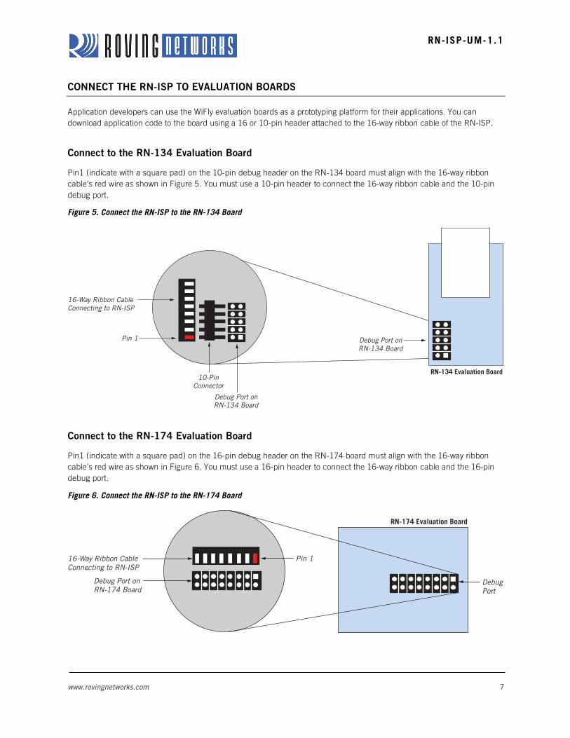
CONNECT THE RN-ISP TO EVALUATION BOARDS
Application developers can use the WiFly evaluation boards as a prototyping platform for their applications. You can
download application code to the board using a 16 or 10-pin header attached to the 16-way ribbon cable of the RN-ISP.
Connect to the RN-134 Evaluation Board
Pin1 (indicate with a square pad) on the 10-pin debug header on the RN-134 board must align with the 16-way ribbon
cable’s red wire as shown in Figure 5. You must use a 10-pin header to connect the 16-way ribbon cable and the 10-pin
debug port.
Figure 5. Connect the RN-ISP to the RN-134 Board
Connect to the RN-174 Evaluation Board
Pin1 (indicate with a square pad) on the 16-pin debug header on the RN-174 board must align with the 16-way ribbon
cable’s red wire as shown in Figure 6. You must use a 16-pin header to connect the 16-way ribbon cable and the 16-pin
debug port.
Figure 6. Connect the RN-ISP to the RN-174 Board
16-Way Ribbon CableConnecting to RN-ISP
Pin 1
10-PinConnector
Debug Port onRN-134 Board
RN-134 Evaluation Board
Debug Port onRN-134 Board
16-Way Ribbon CableConnecting to RN-ISP
Pin 1
RN-174 Evaluation Board
DebugPort
Debug Port on RN-174 Board
www.rovingnetworks.com 8
RN-ISP-UM-1.1
USING ROVING NETWORKS FIRMWARE ON THE WIFLY MODULE
You can use the ISP to monitor and configure the WiFly module while it is running a Roving Networks application.
Additionally, you can go into command mode and configure the various parameters using the ASCII command interface.
The RN-ISP can be used to configure Roving Networks firmware from a Linux, Windows, or Mac computer. However,
before you can use the RN-ISP with a Windows or a Mac computer, you must install FTDI chip drivers from the FTDI
website at http://www.ftdichip.com/Drivers/VCP.htm. Refer to “Appendix A: Installing FTDI drivers for Windows” on page 9
for installation instructions.
NOTE: You cannot develop firmware on a Windows or Mac computer. However, you can use Windows, Mac, or Linux
computers to monitor and configure the firmware.
Launch a terminal emulator program and select the user UART COM port. The default COM port settings are 9,600 baud,
8 bits, no parity, and 1 stop bit. Enter the escape sequence $$$ to go into command mode. The module returns CMD
indicating that it is in command mode.
For a complete list of commands, refer to the command reference section in the WiFly Advanced User Manual, which is
available on the Support page of the Roving Networks web site at http://www.rovingnetworks.com/Support_Overview.
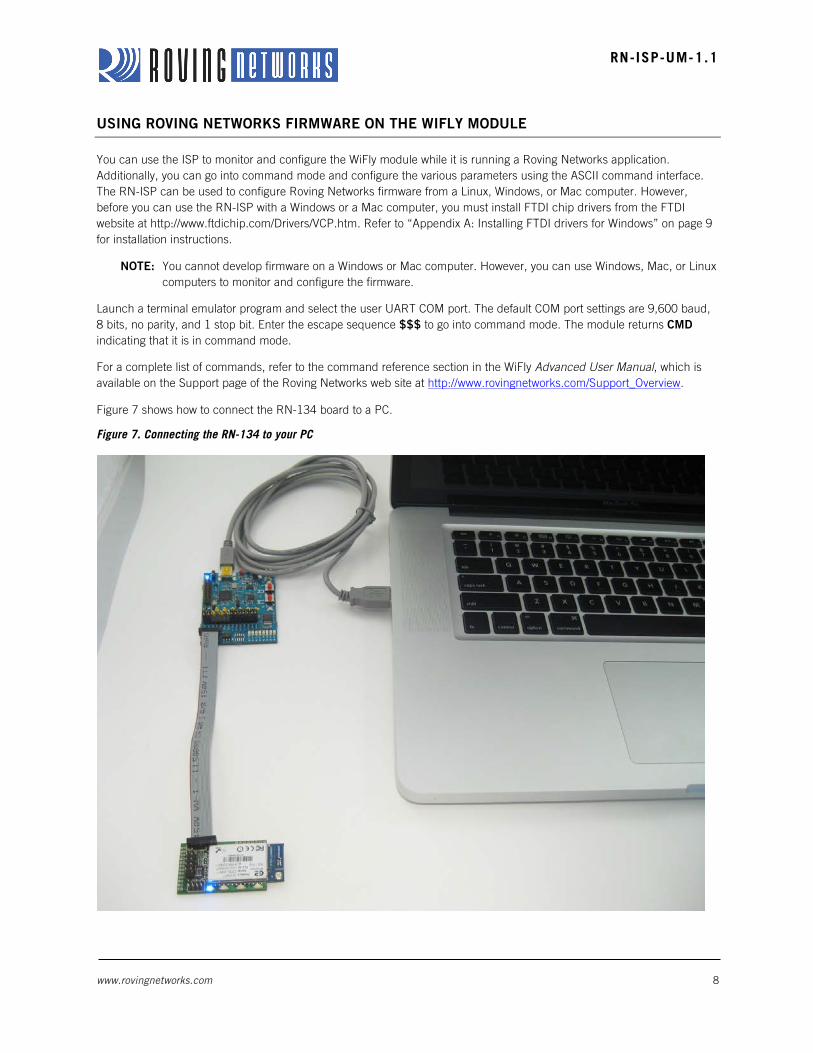
Figure 7 shows how to connect the RN-134 board to a PC.
Figure 7. Connecting the RN-134 to your PC
www.rovingnetworks.com 9
RN-ISP-UM-1.1
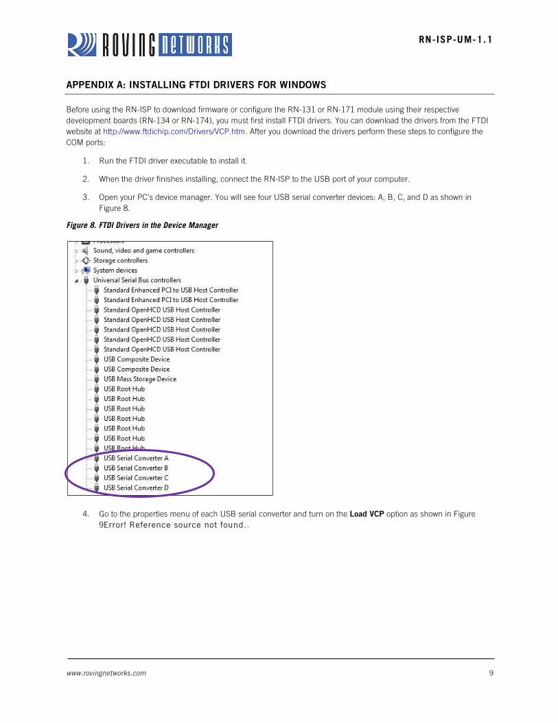
APPENDIX A: INSTALLING FTDI DRIVERS FOR WINDOWS
Before using the RN-ISP to download firmware or configure the RN-131 or RN-171 module using their respective
development boards (RN-134 or RN-174), you must first install FTDI drivers. You can download the drivers from the FTDI
website at http://www.ftdichip.com/Drivers/VCP.htm. After you download the drivers perform these steps to configure the
COM ports:
1. Run the FTDI driver executable to install it.
2. When the driver finishes installing, connect the RN-ISP to the USB port of your computer.
3. Open your PC’s device manager. You will see four USB serial converter devices: A, B, C, and D as shown in
Figure 8.
Figure 8. FTDI Drivers in the Device Manager
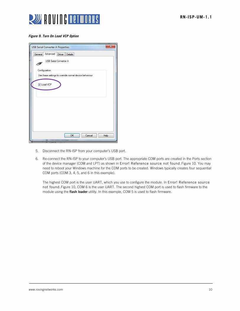
4. Go to the properties menu of each USB serial converter and turn on the Load VCP option as shown in Figure
9Error! Reference source not found..
www.rovingnetworks.com 10
RN-ISP-UM-1.1
Figure 9. Turn On Load VCP Option
5. Disconnect the RN-ISP from your computer’s USB port.
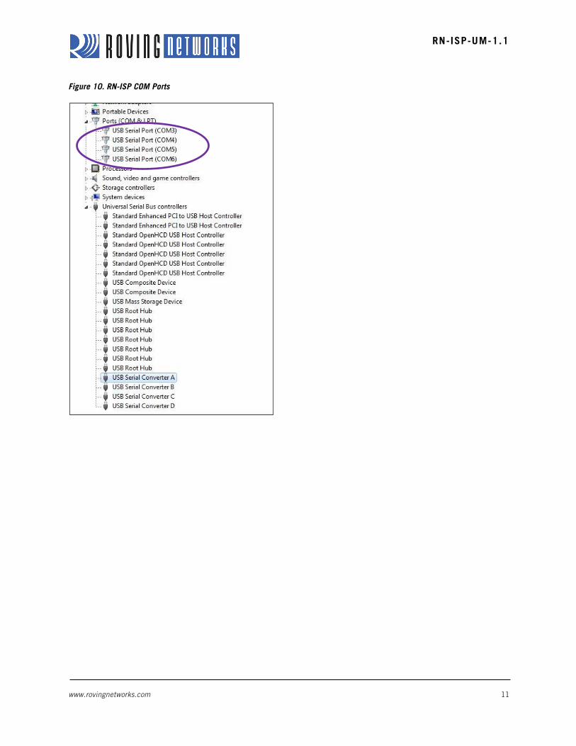
6. Re-connect the RN-ISP to your computer’s USB port. The appropriate COM ports are created in the Ports section
of the device manager (COM and LPT) as shown in Error! Reference source not found.Figure 10. You may
need to reboot your Windows machine for the COM ports to be created. Windows typically creates four sequential
COM ports (COM 3, 4, 5, and 6 in this example).
The highest COM port is the user UART, which you use to configure the module. In Error! Reference source
not found.Figure 10, COM 6 is the user UART. The second highest COM port is used to flash firmware to the
module using the flash loader utility. In this example, COM 5 is used to flash firmware.
www.rovingnetworks.com 11
RN-ISP-UM-1.1
Figure 10. RN-ISP COM Ports
www.rovingnetworks.com 12
RN-ISP-UM-1.1
APPENDIX B: USING THE RN-ISP TO MEASURE THE POWER PROFILE
You can use the RN-ISP to measure the power profile of the application that is running on the WiFly module. This tool is
very useful for plotting the current drawn by the module in different states, such as sleep, idle, and receiving and
transmitting data.
To use this tool, you must have licensed the SDK from Roving Networks and installed it on a Linux computer. When the
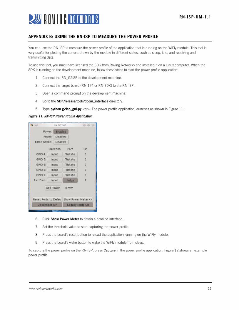
SDK is running on the development machine, follow these steps to start the power profile application:
1. Connect the RN_G2ISP to the development machine.
2. Connect the target board (RN-174 or RN-SDK) to the RN-ISP.
3. Open a command prompt on the development machine.
4. Go to the SDK/release/tools/dcom_interface directory.
5. Type python g2isp_gui.py <cr>. The power profile application launches as shown in Figure 11.
Figure 11. RN-ISP Power Profile Application
6. Click Show Power Meter to obtain a detailed interface.
7. Set the threshold value to start capturing the power profile.
8. Press the board’s reset button to reload the application running on the WiFly module.
9. Press the board’s wake button to wake the WiFly module from sleep.
To capture the power profile on the RN-ISP, press Capture in the power profile application. Figure 12 shows an example
power profile.
www.rovingnetworks.com 13
RN-ISP-UM-1.1
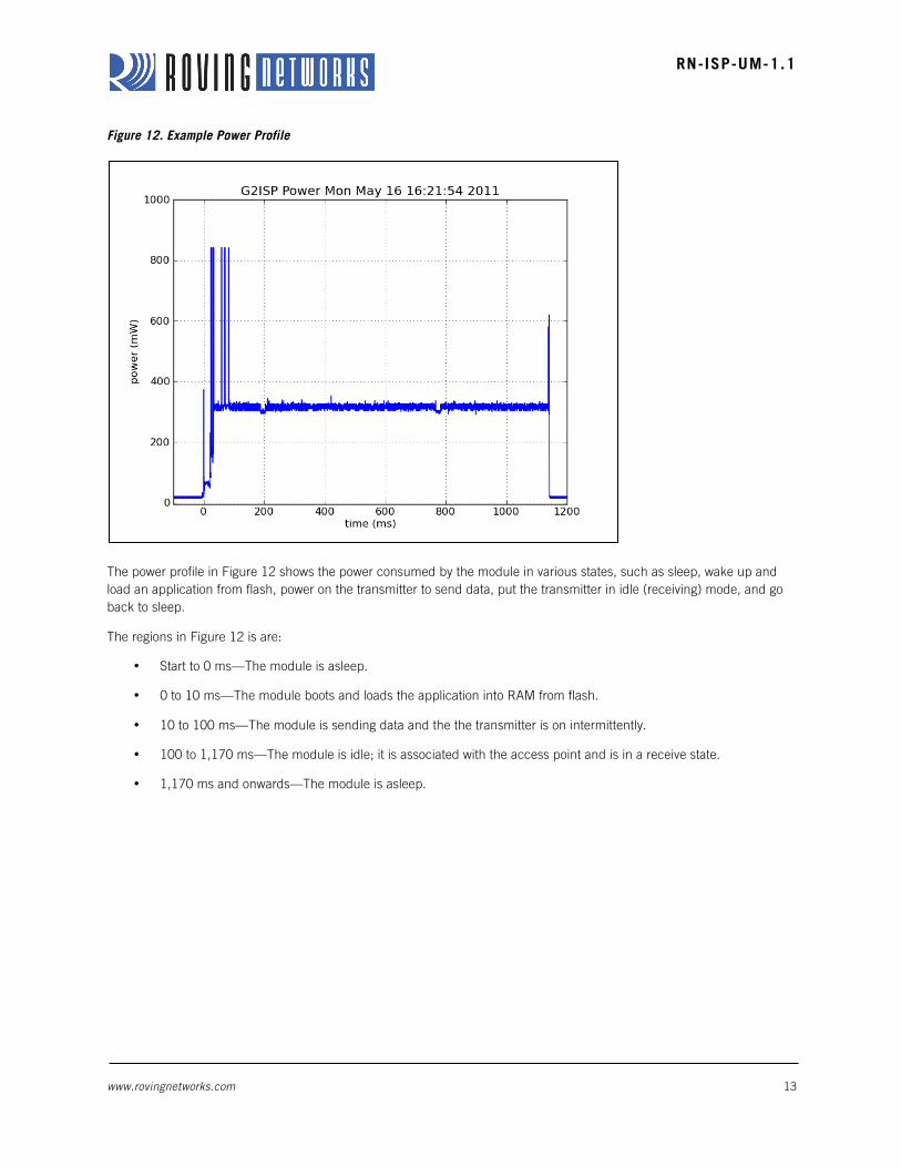
Figure 12. Example Power Profile
The power profile in Figure 12 shows the power consumed by the module in various states, such as sleep, wake up and
load an application from flash, power on the transmitter to send data, put the transmitter in idle (receiving) mode, and go
back to sleep.
The regions in Figure 12 is are:
• Start to 0 ms—The module is asleep.
• 0 to 10 ms—The module boots and loads the application into RAM from flash.
• 10 to 100 ms—The module is sending data and the the transmitter is on intermittently.
• 100 to 1,170 ms—The module is idle; it is associated with the access point and is in a receive state.
• 1,170 ms and onwards—The module is asleep.
www.rovingnetworks.com 14
RN-ISP-UM-1.1
FLASH LOADER UTILITY
It is sometimes convenient to load a binary image without installing and using the SDK. With the flash loader utility, you can
flash the firmware onto the module using a PC. To use the flash loader utility, you must have the RN-ISP and a target
board with a 16-pin debug header.
To set up the hardware, first, connect the target board to the RN-ISP using a 16-pin ribbon cable. Then, connect the
RN-ISP to the PC using a USB cable.
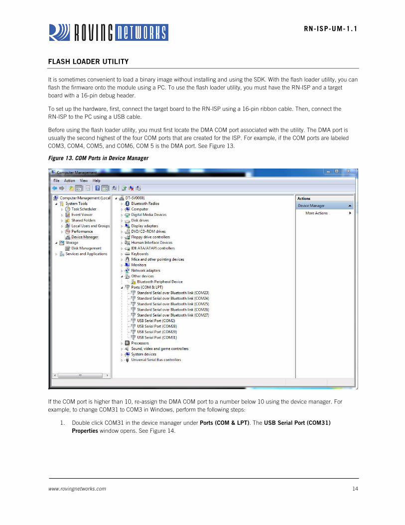
Before using the flash loader utility, you must first locate the DMA COM port associated with the utility. The DMA port is
usually the second highest of the four COM ports that are created for the ISP. For example, if the COM ports are labeled
COM3, COM4, COM5, and COM6, COM 5 is the DMA port. See Figure 13.
Figure 13. COM Ports in Device Manager
If the COM port is higher than 10, re-assign the DMA COM port to a number below 10 using the device manager. For
example, to change COM31 to COM3 in Windows, perform the following steps:
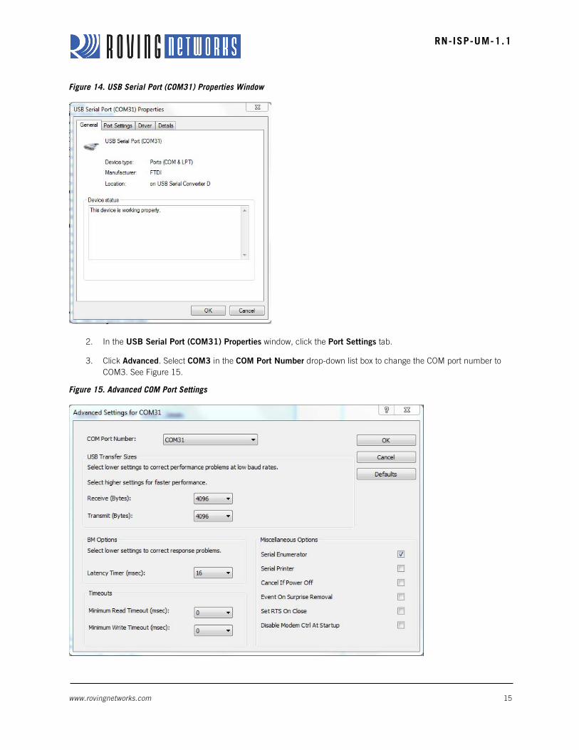
1. Double click COM31 in the device manager under Ports (COM & LPT). The USB Serial Port (COM31)
Properties window opens. See Figure 14.
www.rovingnetworks.com 15
RN-ISP-UM-1.1
Figure 14. USB Serial Port (COM31) Properties Window
2. In the USB Serial Port (COM31) Properties window, click the Port Settings tab.
3. Click Advanced. Select COM3 in the COM Port Number drop-down list box to change the COM port number to
COM3. See Figure 15.
Figure 15. Advanced COM Port Settings
www.rovingnetworks.com 16
RN-ISP-UM-1.1
NOTE: If all ports from COM1 through COM10 are in use, follow the instructions in the COM port reset application
note to clear out the COM ports. The application note is available on the Roving Networks Documentation &
Resources web page at http://www.rovingnetworks.com/resources/show/.
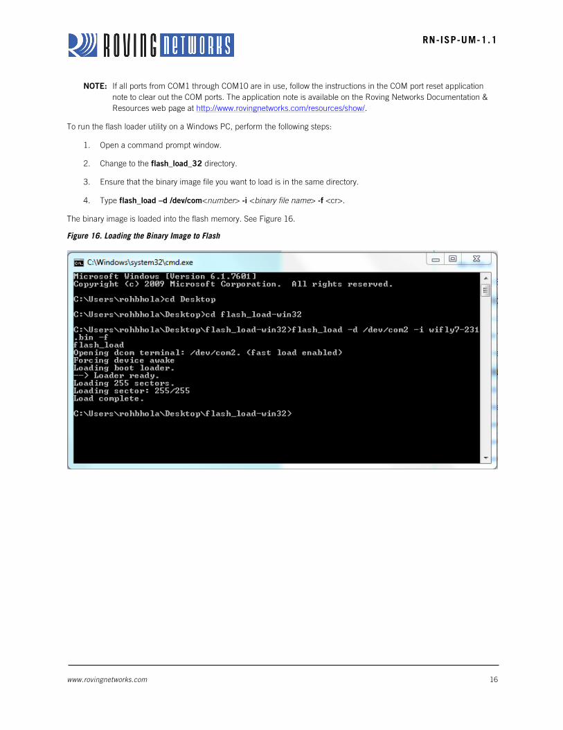
To run the flash loader utility on a Windows PC, perform the following steps:
1. Open a command prompt window.
2. Change to the flash_load_32 directory.
3. Ensure that the binary image file you want to load is in the same directory.
4. Type flash_load –d /dev/com<number> -i <binary file name> -f <cr>.
The binary image is loaded into the flash memory. See Figure 16.
Figure 16. Loading the Binary Image to Flash
www.rovingnetworks.com 17
RN-ISP-UM-1.1
APPENDIX D: LEGACY BOARD DIAGRAM
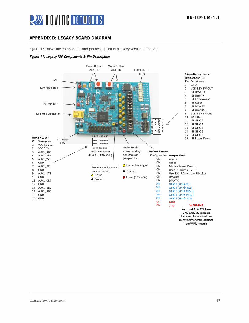
Figure 17 shows the components and pin description of a legacy version of the ISP.
Figure 17. Legacy ISP Components & Pin Description
Mini USB Connector
Jumper BlockAwakeResetModule Power DownUser TX (TX into RN-‐131)User RX (RX from the RN-‐131)DMA RXDMA TXGPIO 8 (SPIàCS)GPIO 6 (SPI à IRQ)GPIO 5 (SPIàMISO)GPIO 4 (SPIàMOSI)GPIO 9 (SPI à SCK)GND 3.3V
Reset ButtonAnd LED
Wake ButtonAnd LED
16-‐pin Debug Header (Debug Conn 16)Pin Description1 GND2 VDD 3.3V SW OUT3 ISP DMA RX4 ISP User TX5 ISP Force Awake6 ISP Reset7 ISP DMA TX8 ISP User RX9 VDD 3.3V SW Out10 GND Out11 ISP GPIO 912 ISP GPIO 413 ISP GPIO 514 ISP GPIO 615 ISP GPIO 816 ISP Power Down
1 3 5 7 9 11 13 15
2 4 6 8 10 12 14 16
ISP Power LED
AUX 1 connector(Port B of FTDI Chip)
1 3 5 7 9 11 13 15
2 4 6 8 10 12 14 16AUX1 HeaderPin Description1 VDD 3.3V J22 VDD 3.3V3 AUX1_BB54 AUX1_BB45 AUX1_TX6 GND7 AUX1_RX8 GND9 AUX1_RTS10 GND11 AUX1_CTS12 GND13 AUX1_BB714 AUX1_BB615 GND16 GND
Probe Hooks corresponding to signals on jumper block
UART Status LEDs
Default Jumper Configuration
ONONONONONONONOFFOFFOFFOFFOFFONON WARNING
You must ALWAYS have GND and 3.3V jumpers
installed. Failure to do so might permanently damage
the WiFly module
Probe hooks for current measurement.
Jumper block signal
Ground
Power (3.3V or 5V)
5V from USB
3.3V Regulated
GND
ISENSEGround
www.rovingnetworks.com 18
RN-ISP-UM-1.1
RESOURCES & RELATED DOCUMENTS
For more information, refer to the following sources, which are available on the Support page on the Roving Networks
website at http://www.rovingnetworks.com/support.php:
• RN-131 Data Sheet
• RN-134 Data Sheet
• RN-171 Data Sheet
• RN-174 Data Sheet
• Advanced User Manual
• COM Port Reset Application Note
• http://www.ftdichip.com/Drivers/VCP.htm (FTDI drivers)

www.rovingnetworks.com 19
RN-ISP-UM-1.1
NOTES

www.rovingnetworks.com 20
RN-ISP-UM-1.1
Roving Networks, Inc.
102 Cooper Court
Los Gatos, CA 95032
+1 (408) 395-5300
www.rovingnetworks.com
Copyright © 2012 Roving Networks. All rights reserved. Roving Networks is a
registered trademark of Roving Networks. Apple Inc., iPhone, iPad, iTunes, Made
for iPhone are registered trademarks of Apple Computer.
Roving Networks reserves the right to make corrections, modifications, and other
changes to its products, documentation and services at any time. Customers
should obtain the latest relevant information before placing orders and should verify
that such information is current and complete.
Roving Networks assumes no liability for applications assistance or customer’s
product design. Customers are responsible for their products and applications
which use Roving Networks components. To minimize customer product risks,
customers should provide adequate design and operating safeguards.
Roving Networks products are not authorized for use in safety-critical applications
(such as life support) where a failure of the Roving Networks product would
reasonably be expected to cause severe personal injury or death, unless officers of
the parties have executed an agreement specifically governing such use.


![WriteNow! ISP Programmer Device List · 2017. 11. 22. · WriteNow! ISP Programmer Device List * = Included free of charge Updated November 2017 Adesto AT25DF011* [SPI] AT25DF021*](https://static.fdocuments.us/doc/165x107/5ff93023f7033723f0432fa1/writenow-isp-programmer-device-2017-11-22-writenow-isp-programmer-device.jpg)