Modern advances in glass-coated microwires: A significant ...
Research ArticleIn Situ SEM Torsion Test of Metallic GlassMicrowires Based on Micro Robotic Manipulation
Chenchen Jiang,1,2 Haojian Lu,1 Ke Cao,1 Wenfeng Wan,1 Yajing Shen,1,3 and Yang Lu1,2
1Department of Mechanical and Biomedical Engineering, City University of Hong Kong, Kowloon, Hong Kong2Center for Advanced Structural Materials (CASM), Shenzhen Research Institute, City University of Hong Kong,Shenzhen 518057, China3Centre for Robotics and Automation, Shenzhen Research Institute, City University of Hong Kong, Shenzhen 518057, China
Correspondence should be addressed to Yajing Shen; [email protected] and Yang Lu; [email protected]
Received 24 March 2017; Accepted 25 July 2017; Published 23 August 2017
Academic Editor: Nicolas Delorme
Copyright © 2017 Chenchen Jiang et al.This is an open access article distributed under the Creative CommonsAttribution License,which permits unrestricted use, distribution, and reproduction in any medium, provided the original work is properly cited.
Microwires, such as metallic, semiconductor, and polymer microwires and carbon fibers, have stimulated great interest due totheir importance in various structural and functional applications. Particularly, metallic glass (MG) microwires, because of theiramorphous atoms arrangement, have some unique mechanical properties compared with traditional metals. Despite the fact thatsubstantial research efforts have been made on the mechanical characterizations of metallic glass microwires under tension orflexural bending, the mechanical properties of microwires under torsional loading have not been well studied, mainly due to theexperimental difficulties, such as the detection of torsion angle, quantitative measurement of the torsional load, and the alignmentbetween the specimen and torque meter. In this work, we implemented the in situ SEM torsion tests of individual La50Al30Ni20metallic glass (MG) microwires successfully based on a self-developed micro robotic mechanical testing system. Unprecedenteddetails, such as the revolving vein-pattern along the torsion direction on MG microwires fracture surface, were revealed. Ourplatform could provide critical insights into understanding the deformation mechanisms of other microwires under torsionalloading and can even be further used for robotic micromanufacturing.
1. Introduction
Microwires, such as metallic [1, 2], semiconducting [3, 4],and composite microwire [5, 6], biomaterial fiber [7], andcarbon fiber [8, 9], have unusual mechanical and physicalproperties, making them promising for various mechatronicapplications in micro electronics devices [10] or solar cells[11]. For example, polymer microwires with high elasticityeven can function as a spring element to produce jumpingor flapping motions in microrobots [12]. ZnO microwires,on the other hand, which have unique piezoelectric property,have been demonstrated to act as microsensor or fieldeffect transistor [13]. Among those crystalline and non-crystalline microstructured materials, BMG (bulk metallicglass) has received tremendous research attention becauseof its unique physical and mechanical properties such asultrahigh strength, high hardness, and large elastic strain[14, 15] due to the amorphous state of the atoms. Compared
with the normal metals having crystalline lattice structures,which can facilitate dislocation movement under stress,making them soft and ductile, MGs, on the other hand,are normally hard and brittle at bulk scales [16]. Recently,MG microwires have received increased interests due totheir different properties compared to their bulk coun-terparts; for instance, magnetic metallic glass microwiresexhibit extremely soft magnetic behavior because of theabsence of magnetocrystalline anisotropy, grain boundaries,and crystalline structure defects [17–20]. However, in-depthunderstanding of the mechanical properties of these novelMG micromaterials is still necessary for developing newapplications, such as micro/nanoelectromechanical system(MEMS/NEMS) devices [21], heterogeneous catalysts [22],and magnetic sensors [23]. What is more, as the variousmicrowires’ applications circumstances have become compli-cated, themechanical property of these materials has becomea bottleneck constraint for long service time.
HindawiScanningVolume 2017, Article ID 6215691, 7 pageshttps://doi.org/10.1155/2017/6215691
2 Scanning
Although there have been extensive studies on themechanical behavior of microwire materials in the past twodecades, such as static tensile test [24–27], micro/nanoinden-tation measurement [28–30], bending measurement [31–33],and dynamic resonance frequency fatigue test [34, 35], littlewas reported on the behavior of microwire under the tor-sional loading [36–38]. Torsion of thin wires is a fundamentaland excellent approach to explore the mechanical behavior,from elastic deformation, through yielding, to the strain-hardening regime. The reason for the rareness of torsiontest of microwire was the great challenge involved in theexperiment, such as the alignment between the specimenand the rotation axis, the detection of torsion angle, and thesensibility and calibration of torque meter. In this paper, weinvestigated the torsion fracture behavior of the La50Al30Ni20MGmicrowire under in situ SEM and compared the fracturesurface with tensile loading test [24–26] based on a self-developed micro robotic mechanical testing system. Afteranalyzing the pattern on the fracture surface, the fracturemechanism of the microwire under torsion loading wasproposed. The fracture resulted from the fact that the localtemperature became very high to themelting point of theMGmaterial and a fluid layer was generated; then the nucleatednano/microvoid caused the failure. The interesting revolvedvein-pattern microstructures were firstly observed by therobot system we developed which we believe can be usedin many other applications in the future, for example, microassembly of nanoelectronic devices.
2. Sample and Experimental Procedures
2.1. MG Microwire Preparation. The metallic glass (MG)microwire samples (dia. 70 𝜇m) used in this work are fab-ricated by rapid quenching of alloy proportions from theirliquid mixture. As the mechanical or magnetic property ofthe microwire is highly related to the microstructure of thematerials [39, 40], the structure and composition should beconfirmed before experiment. The chemical composition ofthe metallic glass is evaluated through the energy dispersiveX-ray spectroscopy (EDS) studies carried out on the MGmicrowires, which reaffirmed the composition to be approx-imately La50Al30Ni20 (in atomic%). X-ray diffraction (XRD)studies on the MG microwires were carried out to confirmthe amorphous nature of the material.
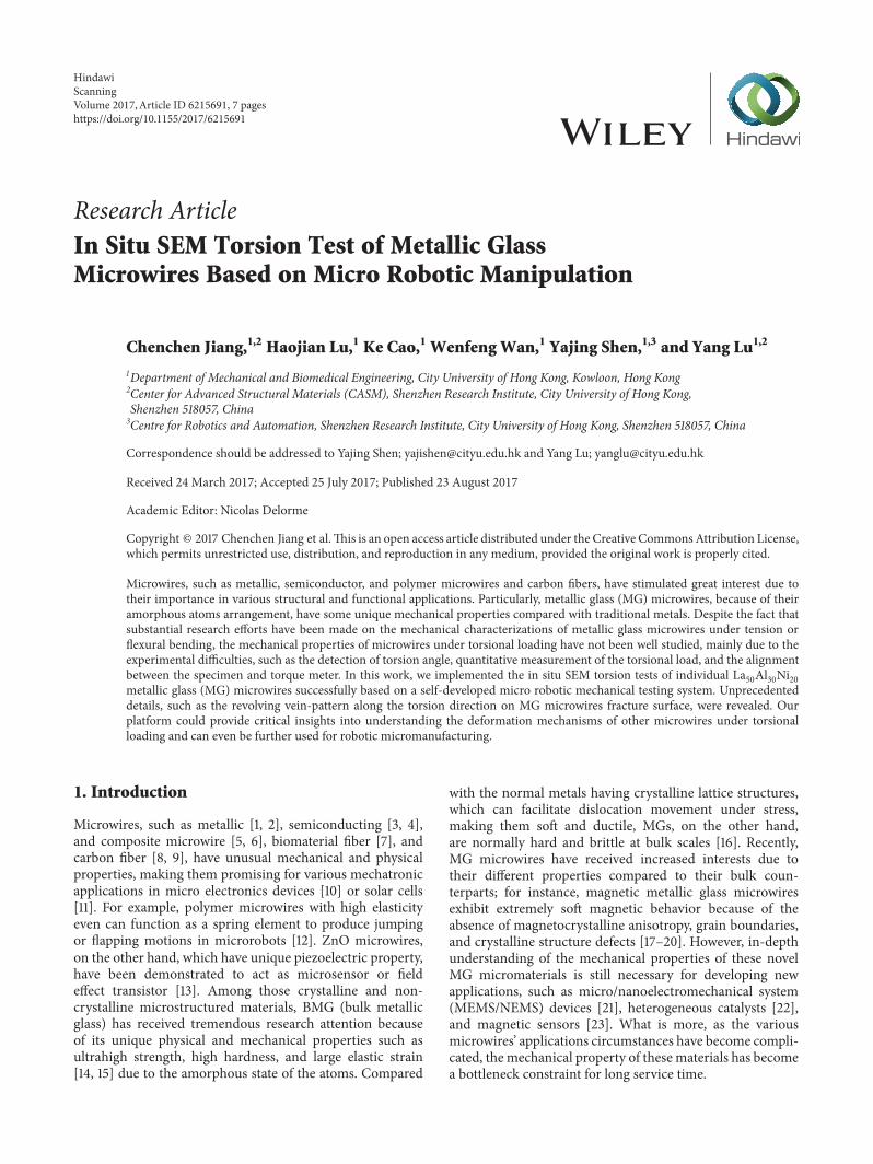
2.2. Micro Robotic Mechanical Testing System. The self-developed micro robotic mechanical testing system is illus-trated in Figure 1(a). The robot mainly comprised two parts[41–43]. The left motion part includes a rotary positionerand two linear positioners. If we set the world coordinate asFigure 1(a) shows, the rotation axis is along the 𝑍 direction.Upon the rotary positioner (RP), the linear positioner (LP 1)which moves in 𝑌 direction is joined. Then another linearpositioner (LP 2) that moves in 𝑋 direction is connectedto the first one. LP 1 and LP 2’s movement directions aremutually perpendicular. Each nanopositioner of the robot isresponsible for one independent movement; thereby the leftpart of the robot has three degrees of freedom (DOFs) intotal: two mutually perpendicular translational movements
(along 𝑋 and 𝑌 directions, resp.) and one rotation (therotation axis is along 𝑧-axis). The right part includes threelinear positioners, which can move independently in 𝑋, 𝑌,𝑍 directions, as Figure 1(a) shows. A metal basement is usedto fix the two parts. Additionally, two T-shape stages werefabricated to clamp the sample at each side as the inset imageshows. With the small footprint of the robot setup, it issuitable for SEM chamber for in situ experiment, as shownby Figure 1(b).
As to the parameters of the positioners, the travel range,resolution, and repeatability for the rotary positioner RP are360∘ endless, (1 × 10⁻⁶)∘ and 5% over the full range, respec-tively. The travel range, resolution, and repeatability of thelinear positioners are 20mm, 1 nm, and 50 nm, respectively.Due to their high accuracy, the compact drive units canachieve the challenging positioning task of precise alignmentin torsion test.
2.3. Experimental Setup. At first, the MG microwire samplewas fixed between the T-shape stage on the left part andthe metal plate by screwing. Then the robot was put in theSEM chamber and connected with the control box throughthe port. Because the SEM imaging system can only providethe 2D image information, it is very difficult to obtain theposition of the sample directly based on the SEM images.An automatic forward-backward alignment strategy wasproposed to address this challenge.
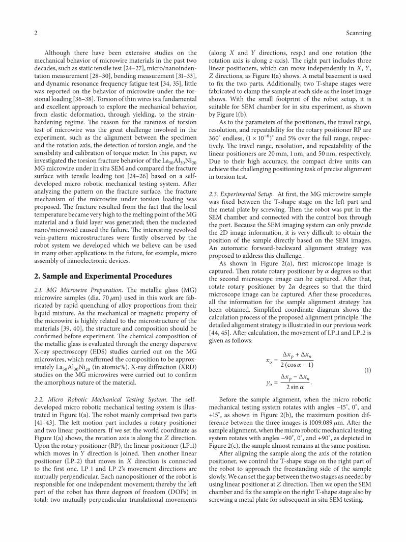
As shown in Figure 2(a), first microscope image iscaptured. Then rotate rotary positioner by 𝛼 degrees so thatthe second microscope image can be captured. After that,rotate rotary positioner by 2𝛼 degrees so that the thirdmicroscope image can be captured. After these procedures,all the information for the sample alignment strategy hasbeen obtained. Simplified coordinate diagram shows thecalculation process of the proposed alignment principle. Thedetailed alignment strategy is illustrated in our previous work[44, 45]. After calculation, the movement of LP 1 and LP 2 isgiven as follows:
𝑥𝑜 =Δ𝑥𝑝 + Δ𝑥𝑛
2 (cos𝛼 − 1)
𝑦𝑜 =Δ𝑥𝑝 − Δ𝑥𝑛
2 sin𝛼.
(1)
Before the sample alignment, when the micro roboticmechanical testing system rotates with angles −15∘, 0∘, and+15∘, as shown in Figure 2(b), the maximum position dif-ference between the three images is 1009.089 𝜇m. After thesample alignment, when themicro roboticmechanical testingsystem rotates with angles −90∘, 0∘, and +90∘, as depicted inFigure 2(c), the sample almost remains at the same position.
After aligning the sample along the axis of the rotationpositioner, we control the T-shape stage on the right part ofthe robot to approach the freestanding side of the sampleslowly.We can set the gap between the two stages as needed byusing linear positioner at𝑍 direction.Then we open the SEMchamber and fix the sample on the right T-shape stage also byscrewing a metal plate for subsequent in situ SEM testing.
Scanning 3
Rotarypositioner
Linearpositioner(Y)LP_1
Linearpositioner (X)
LP_2Sample on T-shape stage
Linearpositioner (X)
Linearpositioner (Y)
Linearpositioner (Z)
Basement
Rotationaxis
X
Y
Z
(a)
Manipulation robot
Sample holder
(b)
Figure 1: (a) is the photography of the robot and the illustration of the different key parts. The rotation axis is along the 𝑍 direction of theworld coordinate. (b) shows that the small footprint of the robot is suitable for the in situ SEM experiment. The inset image is magnificationof the T-shape stage with screws used to clamp the sample.
SampleYp
yP0
Pb
Pb
Po
PoPf
Pf
2
Xp
Xp
xP0
Xf
X0
Xb
ΔXb
ΔXf
Zp
Sample
LP_1
LP_2
(a)
15∘0∘−15∘
494.783 m
1009.089 m200 m
(b)
90∘0∘−90∘
100 m
(c)
Figure 2: (a) Illustration of the alignment process. (b) The images captured from SEM at different angles can be used to calculate how muchLP 1 and LP 2 have to move. (c) The alignment result shows that no matter how many rotations there are, the sample remains almost at thesame position.
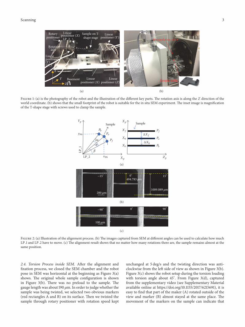
2.4. Torsion Process inside SEM. After the alignment andfixation process, we closed the SEM chamber and the robotpose in SEM was horizontal at the beginning as Figure 3(a)shows. The original whole sample configuration is shownin Figure 3(b). There was no preload to the sample. Thegauge length was about 190 𝜇m. In order to judge whether thesample was being twisted, we selected two obvious markers(red rectangles A and B) on its surface. Then we twisted thesample through rotary positioner with rotation speed kept
unchanged at 5 deg/s and the twisting direction was anti-clockwise from the left side of view as shown in Figure 3(b).Figure 3(c) shows the robot setup during the torsion loadingwith torsion angle about 45∘. From Figure 3(d), capturedfrom the supplementary video (see Supplementary Materialavailable online at https://doi.org/10.1155/2017/6215691), it iseasy to find that part of the maker (A) rotated outside of theview and marker (B) almost stayed at the same place. Themovement of the markers on the sample can indicate that
4 Scanning
(a)
(A)
(B)
Torsion direction
(b)
(c)
(A)
(B)
(d)
(e)
(A)
(B)
(C)
50 m
(f)
Figure 3: Images selected during the experiment. (a) is the robot pose at the beginning of the experiment. (b) is the sample configuration atthe time of (a). The effective length of the sample was about 190𝜇m. Two markers were selected on the surface to judge whether the rotationhappened. The rotation direction was anticlockwise from the left side of view. (c) shows the robot pose during the torsion loading and thedisplacement of marker (A) was much more obvious than marker (B) as (d) shows. The sample fractured at about 55 degrees of rotation asshown in (e). (f) is the final morphology of the sample, which shows that the marker (A) moved a lot and the fracture happened at the middlepart of the sample, partly because of the nonuniformity of the sample diameter or internal defects inside the microwire. The scale bar for the(b), (c), and (d) was 50𝜇m.
the clamping was firm enough. Figures 3(e) and 3(f) wereimages to show the robot pose and sample morphology whenfracture happened at 55∘.
3. Results and Discussions
The shear strain can be calculated by 𝛾 = 𝜑 ∗ 𝑅/𝐿, inwhich 𝜑 indicates the rotation angle;𝑅 and 𝐿 are the diameterand effective length of the microwire. According to theimages captured during the experiment, the MG microwire(dia. 70 𝜇m) with length about 190𝜇m fractured at about 55degrees of distortion, whichmeans themaximumshear strainof the sample was about 17.6%. According to the rotationtheory, the maximum shear strain located at the rightmostside of the sample between the clamp. However, the fracturethat happened at the middle part of the sample may bebecause of the nonuniformity of the diameter or internaldefects inside the microwire.
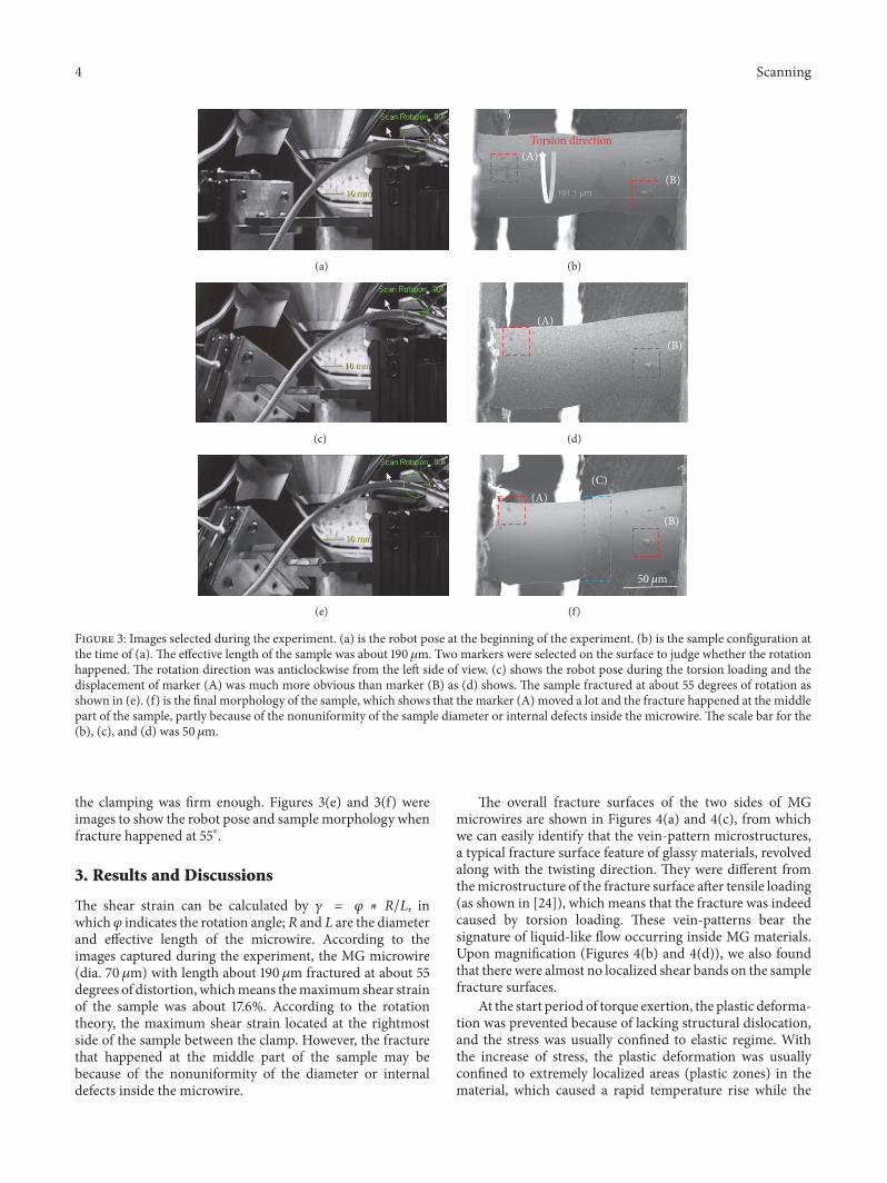
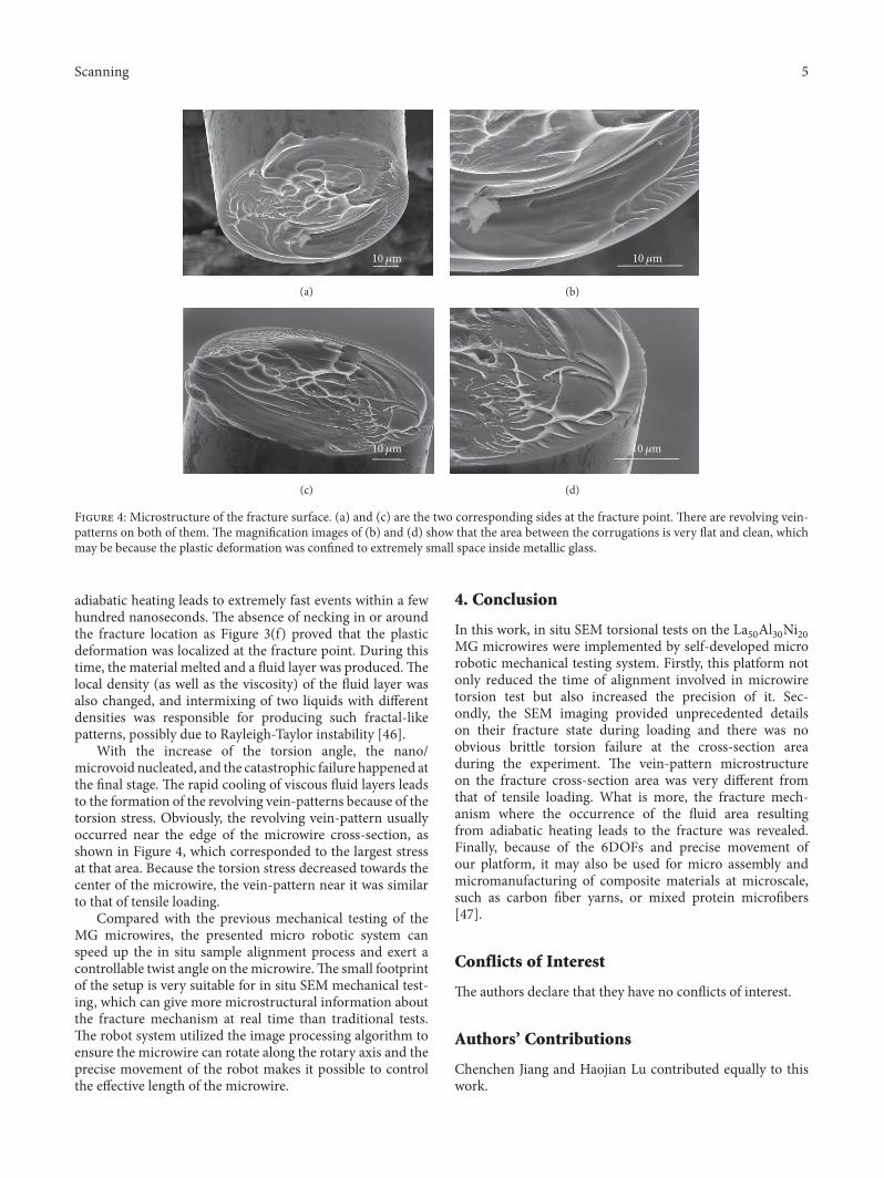
The overall fracture surfaces of the two sides of MGmicrowires are shown in Figures 4(a) and 4(c), from whichwe can easily identify that the vein-pattern microstructures,a typical fracture surface feature of glassy materials, revolvedalong with the twisting direction. They were different fromthemicrostructure of the fracture surface after tensile loading(as shown in [24]), which means that the fracture was indeedcaused by torsion loading. These vein-patterns bear thesignature of liquid-like flow occurring inside MG materials.Upon magnification (Figures 4(b) and 4(d)), we also foundthat there were almost no localized shear bands on the samplefracture surfaces.
At the start period of torque exertion, the plastic deforma-tion was prevented because of lacking structural dislocation,and the stress was usually confined to elastic regime. Withthe increase of stress, the plastic deformation was usuallyconfined to extremely localized areas (plastic zones) in thematerial, which caused a rapid temperature rise while the
Scanning 5
10 m
(a)
10 m
(b)
10 m
(c)
10 m
(d)
Figure 4: Microstructure of the fracture surface. (a) and (c) are the two corresponding sides at the fracture point. There are revolving vein-patterns on both of them. The magnification images of (b) and (d) show that the area between the corrugations is very flat and clean, whichmay be because the plastic deformation was confined to extremely small space inside metallic glass.
adiabatic heating leads to extremely fast events within a fewhundred nanoseconds. The absence of necking in or aroundthe fracture location as Figure 3(f) proved that the plasticdeformation was localized at the fracture point. During thistime, the material melted and a fluid layer was produced.Thelocal density (as well as the viscosity) of the fluid layer wasalso changed, and intermixing of two liquids with differentdensities was responsible for producing such fractal-likepatterns, possibly due to Rayleigh-Taylor instability [46].
With the increase of the torsion angle, the nano/microvoid nucleated, and the catastrophic failure happened atthe final stage. The rapid cooling of viscous fluid layers leadsto the formation of the revolving vein-patterns because of thetorsion stress. Obviously, the revolving vein-pattern usuallyoccurred near the edge of the microwire cross-section, asshown in Figure 4, which corresponded to the largest stressat that area. Because the torsion stress decreased towards thecenter of the microwire, the vein-pattern near it was similarto that of tensile loading.
Compared with the previous mechanical testing of theMG microwires, the presented micro robotic system canspeed up the in situ sample alignment process and exert acontrollable twist angle on themicrowire.The small footprintof the setup is very suitable for in situ SEM mechanical test-ing, which can give more microstructural information aboutthe fracture mechanism at real time than traditional tests.The robot system utilized the image processing algorithm toensure the microwire can rotate along the rotary axis and theprecise movement of the robot makes it possible to controlthe effective length of the microwire.
4. Conclusion
In this work, in situ SEM torsional tests on the La50Al30Ni20MG microwires were implemented by self-developed microrobotic mechanical testing system. Firstly, this platform notonly reduced the time of alignment involved in microwiretorsion test but also increased the precision of it. Sec-ondly, the SEM imaging provided unprecedented detailson their fracture state during loading and there was noobvious brittle torsion failure at the cross-section areaduring the experiment. The vein-pattern microstructureon the fracture cross-section area was very different fromthat of tensile loading. What is more, the fracture mech-anism where the occurrence of the fluid area resultingfrom adiabatic heating leads to the fracture was revealed.Finally, because of the 6DOFs and precise movement ofour platform, it may also be used for micro assembly andmicromanufacturing of composite materials at microscale,such as carbon fiber yarns, or mixed protein microfibers[47].
Conflicts of Interest
The authors declare that they have no conflicts of interest.
Authors’ Contributions
Chenchen Jiang and Haojian Lu contributed equally to thiswork.
6 Scanning
Acknowledgments
The authors gratefully acknowledge the samples from Profes-sor Yong Yang at the Department ofMechanical and Biomed-ical Engineering, City University of Hong Kong. The authorsacknowledge the funding supports by ResearchGrants Coun-cil of the Hong Kong Special Administrative Region (CityU11209914, CityU 11278716), the National Natural ScienceFoundation of China (51301147, 61403323), and Shenzhen(China) Basic Research Project (JCYJ20160329150236426).
References
[1] N. Ranjan, M. Mertig, G. Cuniberti, and W. Pompe, “Dielec-trophoretic growth of metallic nanowires and microwires:Theory and experiments,” Langmuir, vol. 26, no. 1, pp. 552–559,2010.
[2] A. Zhukov, C. Garcıa, J. J. Del Val et al., “Studies of Fe-Cumicrowires with nanogranular structure,” Journal of PhysicsCondensed Matter, vol. 21, no. 3, Article ID 035301, 2009.
[3] J. Hu, Y. Bando, J. Zhan, X. Yuan, T. Sekiguchi, and D.Golberg, “Self-assembly of SiO2 nanowires and Si microwiresinto hierarchical heterostructures on a large scale,” AdvancedMaterials, vol. 17, no. 8, pp. 971–975, 2005.
[4] L. Jiang, Y. Fu, H. Li, and W. Hu, “Single-crystalline, size, andorientation controllable nanowires and ultralong microwires oforganic semiconductor with strong photoswitching property,”Journal of the American Chemical Society, vol. 130, no. 12, pp.3937–3941, 2008.
[5] R. Varga, T. Ryba, Z. Vargova, K. Saksl, V. Zhukova, andA. Zhukov, “Magnetic and structural properties of Ni-Mn-GaHeusler-type microwires,” Scripta Materialia, vol. 65, no. 8, pp.703–706, 2011.
[6] X. Lu, Y. Yu, L. Chen et al., “Poly(acrylic acid)-guided synthesisof helical polyaniline microwires,” Polymer, vol. 46, no. 14, pp.5329–5333, 2005.
[7] S.-P. Tsai, D. W. Howell, Z. Huang et al., “The effect ofprotein fusions on the production and mechanical propertiesof protein-basedmaterials,”Advanced FunctionalMaterials, vol.25, no. 9, pp. 1442–1450, 2015.
[8] E. T.Thostenson,W.Z. Li,D. Z.Wang, Z. F. Ren, andT.W.Chou,“Carbon nanotube/carbon fiber hybrid multiscale composites,”Journal of Applied Physics, vol. 91, no. 9, pp. 6034–6037, 2002.
[9] G.Guitchounts, J. E.Markowitz,W.A. Liberti, andT. J. Gardner,“A carbon-fiber electrode array for long-termneural recording,”Journal of Neural Engineering, vol. 10, no. 4, Article ID 046016,2013.
[10] Q. Yang, W. Wang, S. Xu, and Z. L. Wang, “Enhancing lightemission of ZnOmicrowire-based diodes by piezo-phototroniceffect,” Nano Letters, vol. 11, no. 9, pp. 4012–4017, 2011.
[11] M. C. Putnam, S. W. Boettcher, M. D. Kelzenberg et al., “Simicrowire-array solar cells,” Energy and Environmental Science,vol. 3, no. 8, pp. 1037–1041, 2010.
[12] J. Lee and J. Kim, “Fabrication of strongly anchored, highaspect ratio elastomeric microwires for mechanical and opticalapplications,” Journal of Micromechanics and Microengineering,vol. 21, no. 8, Article ID 085016, 2011.
[13] G. Chai, E. Rusu, L. Chow et al., “Microsensor on single ZnOmicrowire,” in Proceedings of the 2009 International Semicon-ductor Conference, CAS 2009, pp. 275–278, October 2009.
[14] K. S. Nakayama, Y. Yokoyama, G. Xie et al., “Metallic glassnanowire,” Nano Letters, vol. 8, no. 2, pp. 516–519, 2008.
[15] L. Tian, Y.-Q. Cheng, Z.-W. Shan et al., “Approaching the idealelastic limit of metallic glasses,” Nature Communications, vol. 3,article no. 609, 2012.
[16] X. K. Xi, D. Q. Zhao, M. X. Pan, W. H. Wang, Y. Wu, and J. J.Lewandowski, “Fracture of brittle metallic glasses: Brittlenessor plasticity,” Physical Review Letters, vol. 94, no. 12, Article ID125510, 2005.
[17] A. Zhukov, M. Vazquez, J. Velazquez, A. Hernando, andV. Larin, “Magnetic properties of Fe-based glass-coatedmicrowires,” Journal of Magnetism and Magnetic Materials, vol.170, no. 3, pp. 323–330, 1997.
[18] A. Zhukov, K. Chichay, A. Talaat et al., “Manipulation ofmagnetic properties of glass-coated microwires by annealing,”Journal of Magnetism andMagnetic Materials, vol. 383, pp. 232–236, 2015.
[19] A. Zhukov, M. Ipatov, and V. Zhukova, “Advances in giant mag-netoimpedance of materials,” Handbook of Magnetic Materials,vol. 24, pp. 139–236, 2015.
[20] V. Zhukova, M. Ipatov, and A. Zhukov, “Thin magnetically softwires for magnetic microsensors,” Sensors, vol. 9, no. 11, pp.9216–9240, 2009.
[21] P. Sharma, N. Kaushik, H. Kimura, Y. Saotome, and A. Inoue,“Nano-fabrication with metallic glass - an exotic material fornano-electromechanical systems,” Nanotechnology, vol. 18, no.3, Article ID 035302, 2007.
[22] M. Zhao, K. Abe, S.-I. Yamaura, Y. Yamamoto, and N. Asao,“Fabrication of Pd-Ni-P metallic glass nanoparticles and theirapplication as highly durable catalysts in methanol electro-oxidation,” Chemistry of Materials, vol. 26, no. 2, pp. 1056–1061,2014.
[23] T. A. Phan, M. Hara, H. Oguchi, and H. Kuwano, “Currentsensors using Fe-B-Nd-Nb magnetic metallic glass micro-cantilevers,” Microelectronic Engineering, vol. 135, pp. 28–31,2015.
[24] A. Banerjee, C. Jiang, L. Lohiya, Y. Yang, and Y. Lu, “Fracto-emission in lanthanum-based metallic glass microwires underquasi-static tensile loading,” Journal of Applied Physics, vol. 119,no. 15, Article ID 155102, 2016.
[25] H. Sun, Z. Ning, G. Wang et al., “Tensile strength reliabilityanalysis of Cu48Zr48Al4 amorphous microwires,” Metals, vol.6, no. 12, article no. 296, 2016.
[26] H. Shen, D. Xing, H. Wang et al., “Tensile properties andfracture reliability ofmelt-extracted Gd-rich amorphous wires,”Materials Research, vol. 18, pp. 66–71, 2015.
[27] Y. Lu and J. Lou, “Quantitative in-situ nanomechanical charac-terization of metallic nanowires,” JOM, vol. 63, no. 9, pp. 35–42,2011.
[28] P. Kumar and M. S. R. N. Kiran, “Nanomechanical characteri-zation of indium nano/microwires,”Nanoscale Research Letters,vol. 5, no. 7, pp. 1085–1092, 2010.
[29] Z. Liu, X. Yan, Z. Lin, Y. Huang, H. Liu, and Y. Zhang,“Mechanical properties and indentation-induced damage ofhigh-quality ZnO microwires,”Materials Research Bulletin, vol.47, no. 3, pp. 750–754, 2012.
[30] H. Zhang, K. W. Siu, W. Liao, Q. Wang, Y. Yang, and Y. Lu, “Insitu mechanical characterization of CoCrCuFeNi high-entropyalloy micro/nano-pillars for their size-dependent mechanicalbehavior,” Materials Research Express, vol. 3, no. 9, Article ID094002, 2016.
Scanning 7
[31] S. Maekawa, K. Takashima, M. Shimojo et al., “Fatigue tests ofNi-P amorphous alloymicrocantilever beams,” Japanese Journalof Applied Physics, Part 1: Regular Papers and Short Notes andReview Papers, vol. 38, no. 12 B, pp. 7194–7198, 1999.
[32] M. M. McClarty, J. P. Bruce, M. S. Freund, and D. R. Oliver,“Piezoresistive characterization of bottom-up, n-type siliconmicrowires undergoing bend deformation,” Applied PhysicsLetters, vol. 106, no. 2, Article ID 022107, 2015.
[33] S. K. Deb Nath, H. Tohmyoh, and M. A. Salam Akanda,“Evaluation of elastic, elastic-plastic properties of thin Pt wireby mechanical bending test,” Applied Physics A: MaterialsScience and Processing, vol. 103, no. 2, pp. 493–496, 2011.
[34] G. Khatibi, A. Betzwar-Kotas, V. Groger, and B. Weiss, “Astudy of the mechanical and fatigue properties of metallicmicrowires,” Fatigue and Fracture of Engineering Materials andStructures, vol. 28, no. 8, pp. 723–733, 2005.
[35] P. Li, Q. Liao, S. Yang et al., “In situ transmission electronmicroscopy investigation on fatigue behavior of single ZnOwires under high-cycle strain,” Nano Letters, vol. 14, no. 2, pp.480–485, 2014.
[36] Y. J. Dai, Y. Huan, M. Gao et al., “Development of a high-resolution micro-torsion tester for measuring the shear mod-ulus of metallic glass fibers,”Measurement Science and Technol-ogy, vol. 26, no. 2, Article ID 025902, 2015.
[37] D. Liu, Y. He, X. Tang, H. Ding, P. Hu, and P. Cao, “Sizeeffects in the torsion of microscale copper wires: experimentand analysis,” Scripta Materialia, vol. 66, no. 6, pp. 406–409,2012.
[38] C. Jiang, D. Hu, and Y. Lu, “Digital micromirror device (DMD)-based high-cycle torsional fatigue testing micromachine for 1Dnanomaterials,”Micromachines, vol. 7, no. 3, article 49, 2016.
[39] V. Zhukova, A. F. Cobeo, A. Zhukov et al., “Correlation betweenmagnetic and mechanical properties of devitrified glass-coatedFe71.8Cu1Nb3.1Si15B9.1 microwires,” Journal of Magnetism andMagnetic Materials, vol. 249, no. 1-2, pp. 79–84, 2002.
[40] A. Zhukov, M. Ipatov, A. Talaat et al., “Correlation of crystallinestructure with magnetic and transport properties of glass-coated microwires,” Crystals, vol. 7, no. 2, p. 41, 2017.
[41] Y. Shen, Z. Zhang, and T. Fukuda, “Bending spring rateinvestigation of nanopipette for cell injection,” Nanotechnology,vol. 26, no. 15, Article ID 155702, 2015.
[42] W. Shang,H. Lu,W.Wan, T. Fukuda, andY. Shen, “Vision-basednano robotic system for high-throughput non-embedded cellcutting,” Scientific Reports, vol. 6, Article ID 22534, 2016.
[43] W. Wan, H. Lu, V. Zhukova, M. Ipatov, A. Zhukov, and Y. Shen,“Surface defect detection of magnetic microwires by miniaturerotatable robot inside SEM,” AIP Advances, vol. 6, no. 9, ArticleID 095309, 2016.
[44] Y. Shen, W. Wan, H. Lu, T. Fukuda, and W. Shang, “Automaticsample alignment under microscopy for 360∘ imaging based onthe nanorobotic manipulation system,” IEEE Transactions onRobotics, vol. 33, no. 1, pp. 220–226, 2017.
[45] Y. Shen, W. Wan, L. Zhang, L. Yong, H. Lu, and W. Ding,“Multidirectional image sensing for microscopy based on arotatable robot,” Sensors (Switzerland), vol. 15, no. 12, pp. 31566–31580, 2015.
[46] D. H. Sharp, “An overview of rayleigh-taylor instability,” PhysicaD: Nonlinear Phenomena, vol. 12, no. 1-3, pp. 3–IN10, 1984.
[47] Z. Huang, Y. Lu, R. Majithia et al., “Size dictates mechanicalproperties for protein fibers self-assembled by the drosophilahox transcription factor ultrabithorax,” Biomacromolecules, vol.11, no. 12, pp. 3644–3651, 2010.

Submit your manuscripts athttps://www.hindawi.com
Hindawi Publishing Corporationhttp://www.hindawi.com Volume 2014
High Energy PhysicsAdvances in
The Scientific World JournalHindawi Publishing Corporation http://www.hindawi.com Volume 2014
Hindawi Publishing Corporationhttp://www.hindawi.com Volume 2014
FluidsJournal of
Atomic and Molecular Physics
Journal of
Hindawi Publishing Corporationhttp://www.hindawi.com Volume 2014
Hindawi Publishing Corporationhttp://www.hindawi.com Volume 2014
Advances in Condensed Matter Physics
OpticsInternational Journal of
Hindawi Publishing Corporationhttp://www.hindawi.com Volume 2014
Hindawi Publishing Corporationhttp://www.hindawi.com Volume 2014
AstronomyAdvances in
International Journal of
Hindawi Publishing Corporationhttp://www.hindawi.com Volume 2014
Superconductivity
Hindawi Publishing Corporationhttp://www.hindawi.com Volume 2014
Statistical MechanicsInternational Journal of
Hindawi Publishing Corporationhttp://www.hindawi.com Volume 2014
GravityJournal of
Hindawi Publishing Corporationhttp://www.hindawi.com Volume 2014
AstrophysicsJournal of
Hindawi Publishing Corporationhttp://www.hindawi.com Volume 2014
Physics Research International
Hindawi Publishing Corporationhttp://www.hindawi.com Volume 2014
Solid State PhysicsJournal of
Computational Methods in Physics
Journal of
Hindawi Publishing Corporationhttp://www.hindawi.com Volume 2014
Hindawi Publishing Corporationhttp://www.hindawi.com Volume 2014
Soft MatterJournal of
Hindawi Publishing Corporationhttp://www.hindawi.com
AerodynamicsJournal of
Volume 2014
Hindawi Publishing Corporationhttp://www.hindawi.com Volume 2014
PhotonicsJournal of
Hindawi Publishing Corporationhttp://www.hindawi.com Volume 2014
Journal of
Biophysics
Hindawi Publishing Corporationhttp://www.hindawi.com Volume 2014
ThermodynamicsJournal of