In Situ Chemical Oxidation for Groundwater Remediation: New Developments … remediation/3 In... ·...
29
In Situ Chemical Oxidation for Groundwater Remediation: New Developments and Directions Michelle Crimi Associate Professor Clarkson University Institute for a Sustainable Environment July 4 th , 2014
Transcript of In Situ Chemical Oxidation for Groundwater Remediation: New Developments … remediation/3 In... ·...
In Situ Chemical Oxidation for Groundwater Remediation: New
Developments and Directions
Michelle Crimi Associate Professor Clarkson University Institute for a Sustainable Environment July 4th, 2014
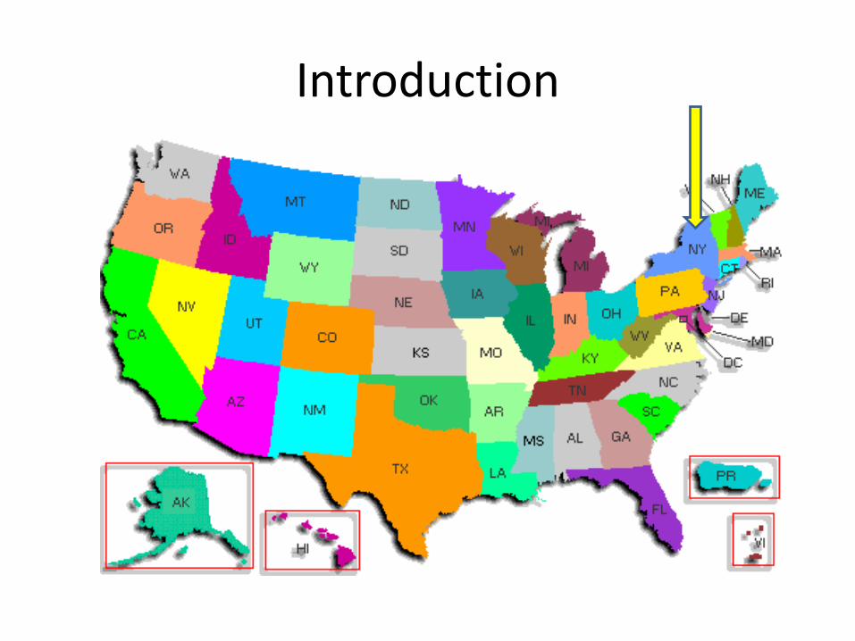
Introduction
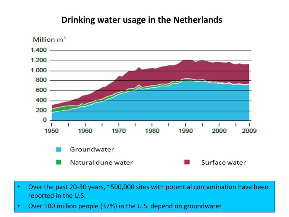
Drinking water usage in the Netherlands
• Over the past 20-30 years, ~500,000 sites with potential contamination have been reported in the U.S.
• Over 100 million people (37%) in the U.S. depend on groundwater
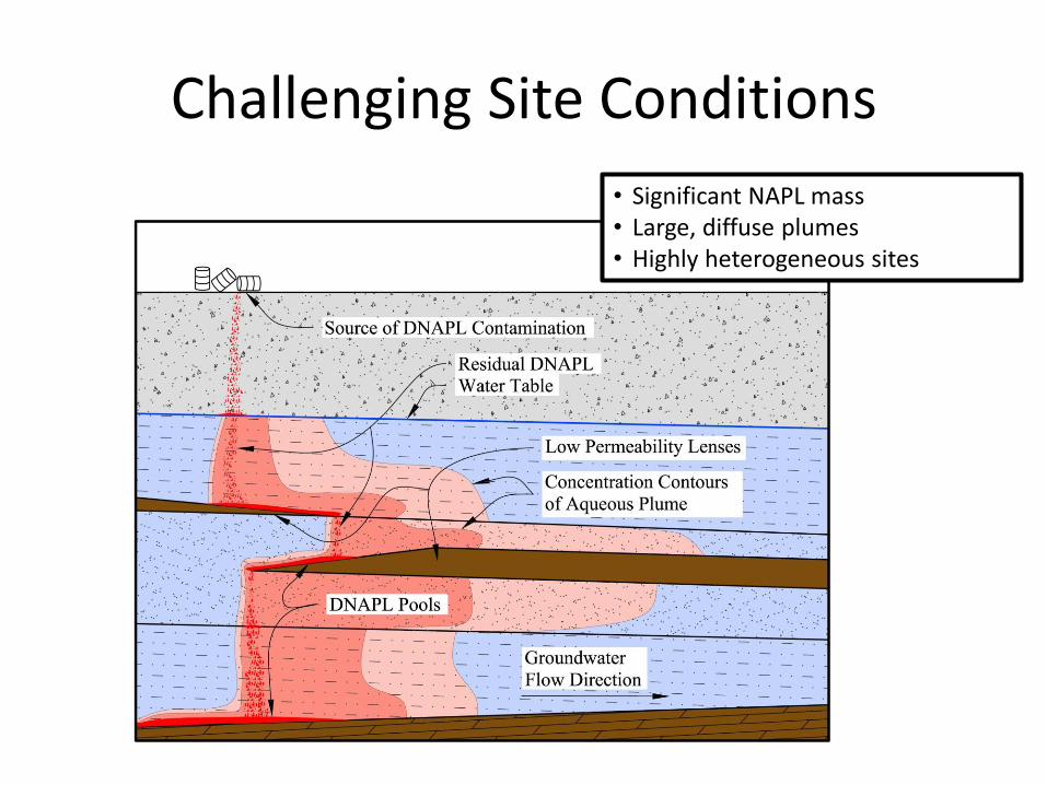
Challenging Site Conditions
• Significant NAPL mass • Large, diffuse plumes • Highly heterogeneous sites
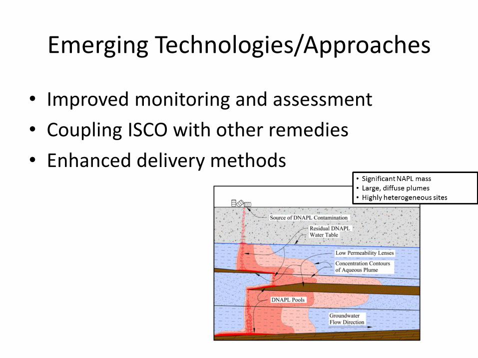
Emerging Technologies/Approaches
• Improved monitoring and assessment
• Coupling ISCO with other remedies
• Enhanced delivery methods
Improved Monitoring / Assessment
• Field methods
– Integrated use of real-time monitoring methods for process control
• Automated, real-time sensor networks
– Oxidation-reduction potential (ORP) and electrical conductivity (EC) probes connected to data loggers
• Real-time data for oxidant distribution
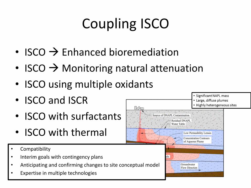
Coupling ISCO
• ISCO Enhanced bioremediation
• ISCO Monitoring natural attenuation
• ISCO using multiple oxidants
• ISCO and ISCR
• ISCO with surfactants
• ISCO with thermal
• Compatibility
• Interim goals with contingency plans
• Anticipating and confirming changes to site conceptual model
• Expertise in multiple technologies
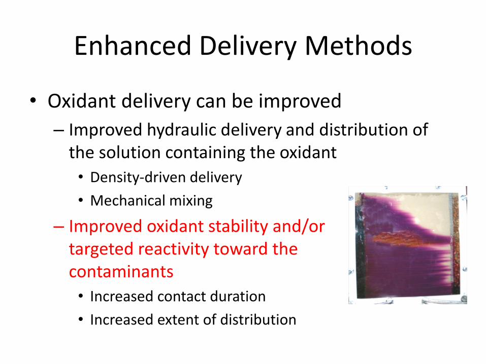
Enhanced Delivery Methods
• Oxidant delivery can be improved
– Improved hydraulic delivery and distribution of the solution containing the oxidant
• Density-driven delivery
• Mechanical mixing
– Improved oxidant stability and/or targeted reactivity toward the contaminants
• Increased contact duration
• Increased extent of distribution
Examples
• Polymers and delivery aids
– Improve movement into low permeability zones and contact between oxidant and contaminant
• Encapsulated oxidants
– Slow and long-term release of oxidant due to diffusion or due to interaction of contaminant with encapsulating material
• Wax cylinders containing oxidant

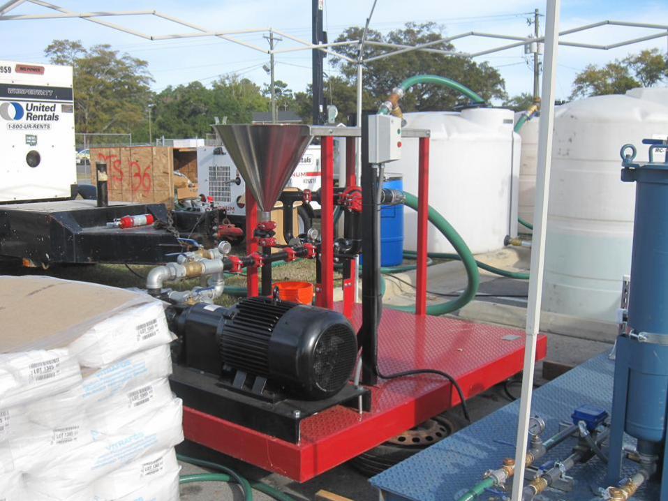
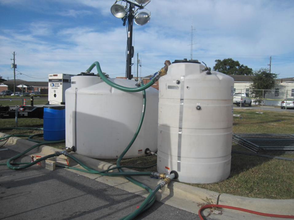
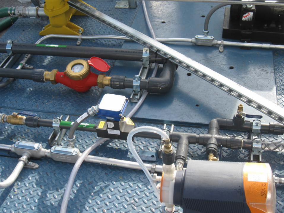
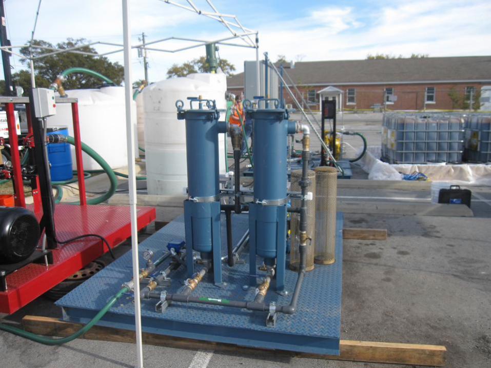
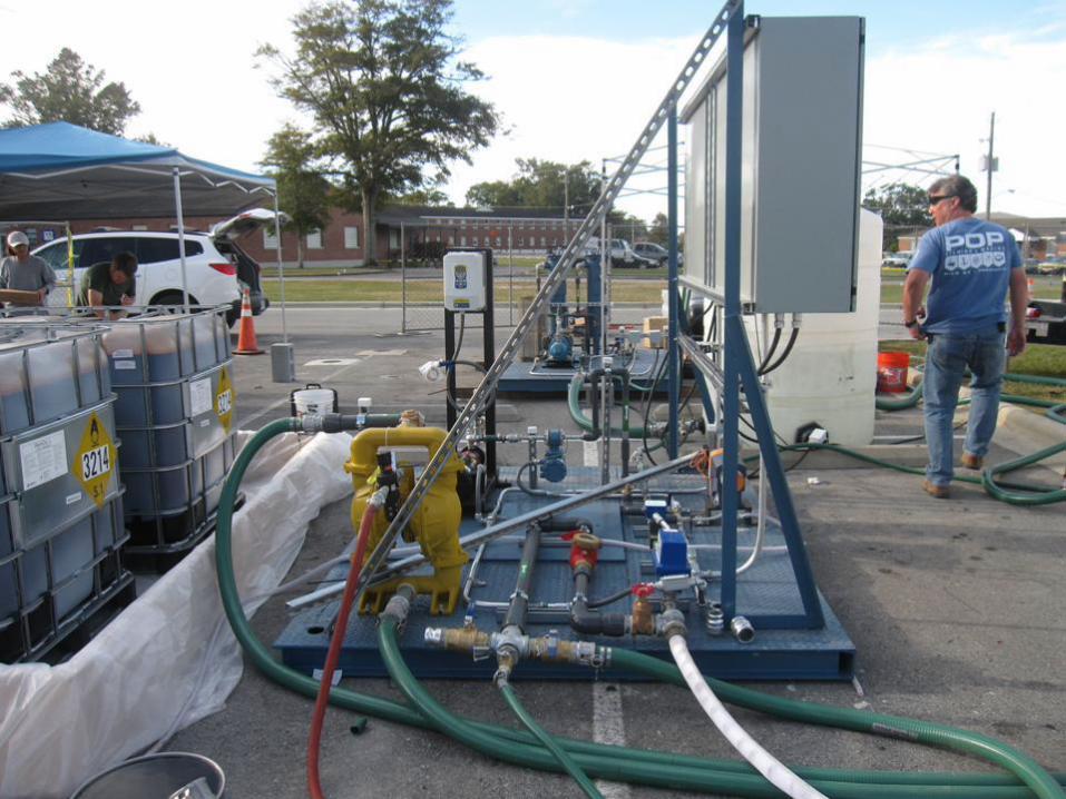
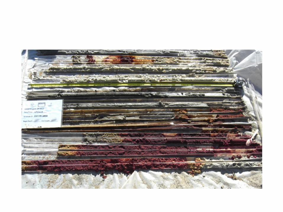
Polymers for enhanced oxidant delivery
Case Study

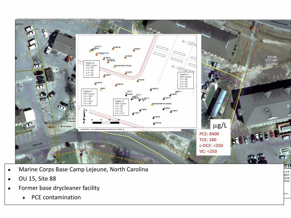
● Marine Corps Base Camp Lejeune, North Carolina
● OU 15, Site 88
● Former base drycleaner facility
PCE contamination
PCE: 8400 TCE: 180 c-DCE: <250 VC: <250
mg/L
Depths of CMT 1 ports: 1-2 = 33’ 1-3 = 44’ 1-4 = 53’ 1-5 = 58’
Depths of CMT 2 ports: 2-2 = 30.5’ 2-3 = 36’ 2-4 = 43.5’ 2-5 = 58’
Depths of CMT 3 ports: 3-2 = 40’ 3-3 = 47’ 3-4 = 53’ 3-5 = 57.5’
Depths of CMT 4 ports: 4-1 = 40’ 4-2 = 49’ 4-3 = 54’ 4-4 = 58’


25
30
35
40
45
50
55
60
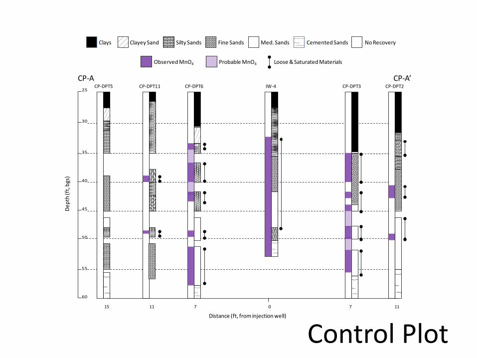
CP-DPT5 CP-DPT11 CP-DPT6 CP-DPT3IW-4 CP-DPT2
0 7 1171115
De
pth
(ft,
bgs
)
Distance (ft, from injection well)
Clays Clayey Sand Silty Sands Fine Sands Med. Sands Cemented Sands No Recovery
Observed MnO4 Probable MnO4 Loose & Saturated Materials
CP-A CP-A’
Control Plot
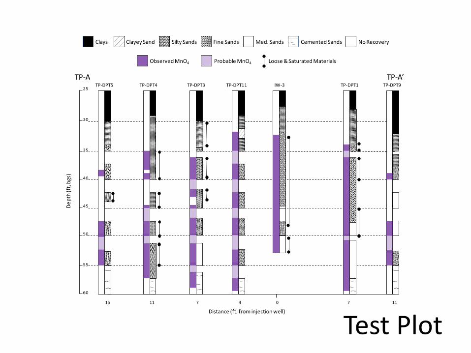
Test Plot
Clays Clayey Sand Silty Sands Fine Sands Med. Sands Cemented Sands No Recovery
Observed MnO4 Probable MnO4 Loose & Saturated Materials
25
30
35
40
45
50
55
60
TP-DPT5 TP-DPT4 TP-DPT3 TP-DPT1IW-3 TP-DPT9
0 7 1171115
De
pth
(ft,
bgs
)
Distance (ft, from injection well)
TP-DPT11
4
TP-A TP-A’

N
N
N
N
Control Plot: Sweep = 33% Test Plot: Sweep = 66%
Slow release oxidants
Case Study
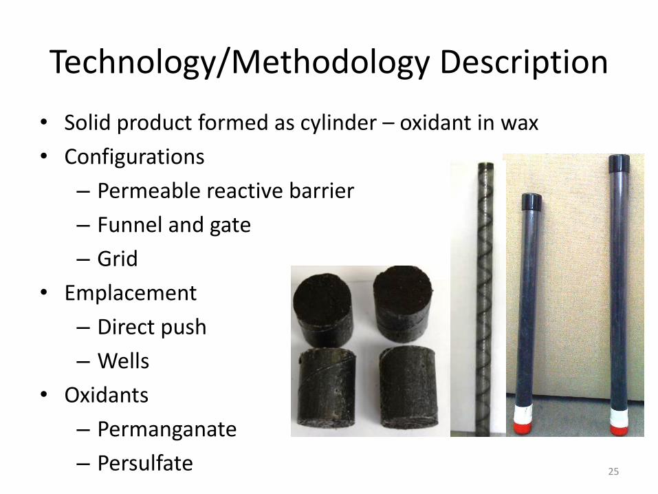
• Solid product formed as cylinder – oxidant in wax
• Configurations
– Permeable reactive barrier
– Funnel and gate
– Grid
• Emplacement
– Direct push
– Wells
• Oxidants
– Permanganate
– Persulfate
Technology/Methodology Description
25
26
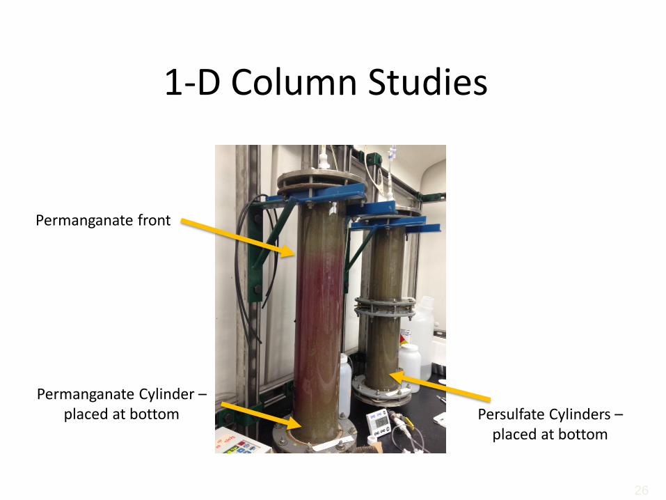
Permanganate Cylinder – placed at bottom Persulfate Cylinders –
placed at bottom
Permanganate front
1-D Column Studies
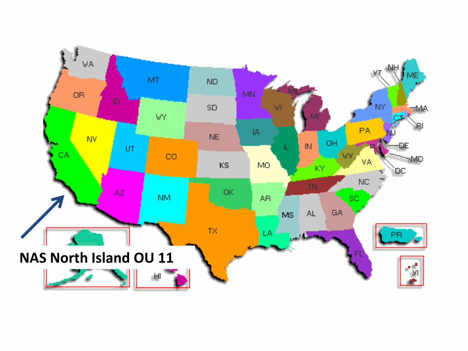
NAS North Island OU 11
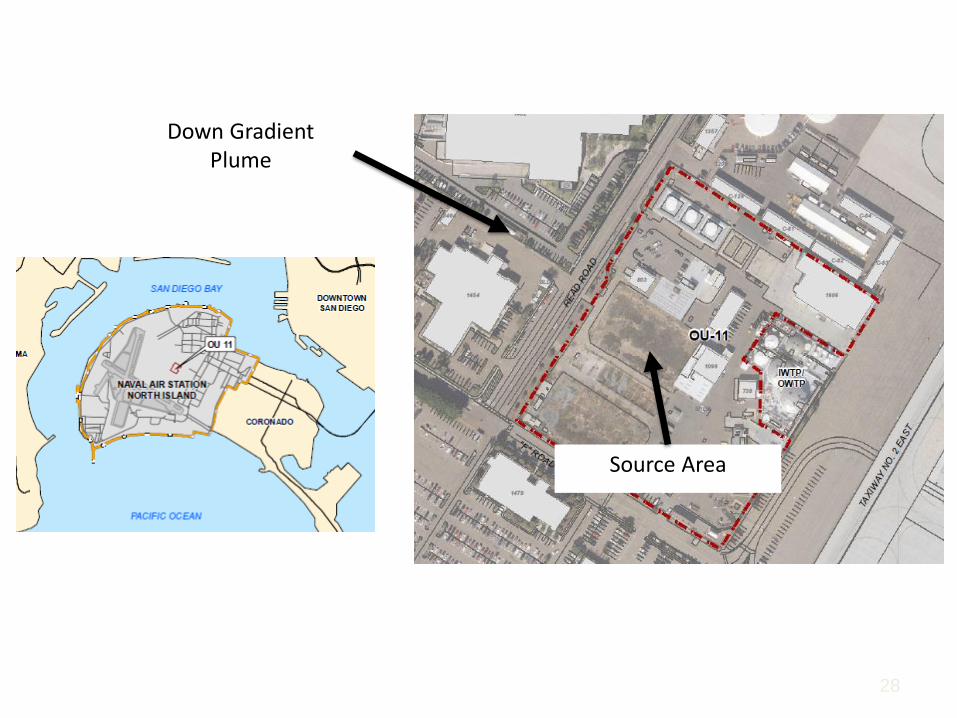
28
Source Area
Down Gradient Plume
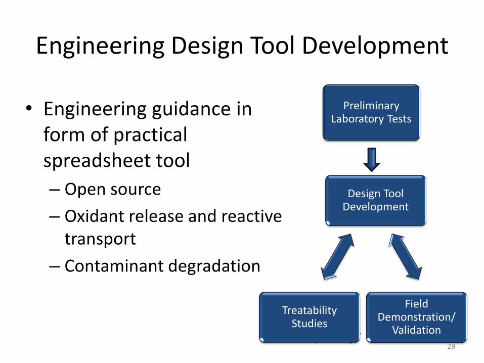
Engineering Design Tool Development
• Engineering guidance in form of practical spreadsheet tool
– Open source
– Oxidant release and reactive transport
– Contaminant degradation
29
Design Tool Development
Field Demonstration/
Validation
Treatability Studies
Preliminary Laboratory Tests