In-Service Inspection Program for the SRS Waste Tanks - SRS CAB
21
1 In-Service Inspection Program for the SRS Waste Tanks: Update 9/01/09 Karthik Subramanian SRR, Office of the Chief Engineer SRR-STI-2009-00532
Transcript of In-Service Inspection Program for the SRS Waste Tanks - SRS CAB

1
In-Service Inspection Program for the SRS Waste Tanks: Update
9/01/09
Karthik SubramanianSRR, Office of the Chief Engineer
SRR-STI-2009-00532

2
Acronyms
• SRR: Savannah River Remediation
• SI: Structural Integrity• ISI: In-Service Inspection• Kgal: Thousands of
gallons• Mgal: Millions of gallons• SRNL: Savannah River
National Laboratory• SST: Single Shell Tank• DST: Double Shell Tank• VSC: Vapor Space
Corrosion
• GAO: Government Accountability Office
• DNFSB: Defense Nuclear Facilities Safety Board
• TSIP: Tank Structural Integrity Panel
• SCC: Stress Corrosion Cracking
• AUT: Automated Ultrasonic Inspection
3
Safety/Security
• SRR Committed to Safety and Security Excellence
• Still THE priority• SRR will continue the
SRS safety tradition• Security is like safety:
SRR will keep it front and center

4
Outline
• Calendar Year 2008 Inspection Results
• Waste Tank Design• Structural Integrity (SI) Program• Corrosion Control Program• In-Service Inspection (ISI) Program• SRR Program Status

5
CY2008 Inspection Results
• WSRC-STI-2009-00352, “Annual Radioactive Waste Tank Inspection Program – 2008”
• 6782 photographs• 1633 visual/video inspections
• Two new leaksites identified– Tank 5 (during final cleaning) and Tank 12(during
waste removal)– Consistent with known degradation mechanisms in
non-compliant, old-style Type I/II tanks with partial secondary containment
– Specific response/communication plans during waste removal and cleaning activities
6
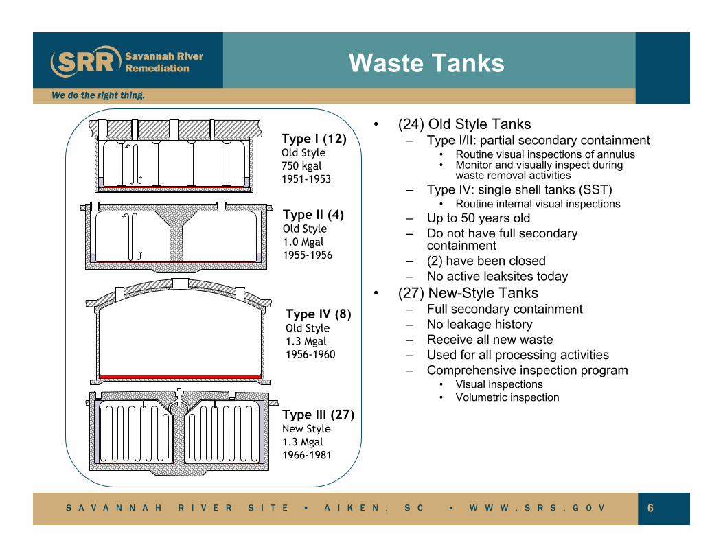
Type I (12)Old Style750 kgal1951-1953
Type II (4)Old Style1.0 Mgal1955-1956
Type III (27)New Style1.3 Mgal 1966-1981
Type IV (8)Old Style1.3 Mgal 1956-1960
Waste Tanks
• (24) Old Style Tanks– Type I/II: partial secondary containment
• Routine visual inspections of annulus• Monitor and visually inspect during
waste removal activities– Type IV: single shell tanks (SST)
• Routine internal visual inspections– Up to 50 years old– Do not have full secondary
containment– (2) have been closed– No active leaksites today
• (27) New-Style Tanks– Full secondary containment– No leakage history– Receive all new waste– Used for all processing activities– Comprehensive inspection program
• Visual inspections• Volumetric inspection

7
Structural Integrity Program
• Waste tanks provide critical interim containment for waste prior to processing and permanent disposal
• Comprehensive integrated approach to maintaining structural integrity of tanks, a critical component of operations
• Evolving program to successfully address emerging issues and preclude consequential degradation
Structural Integrity
Controls
Design &Fabrication
OperationalHistory
FailureAnalysis
In-ServiceInspection
DegradationMechanisms
FractureAnalysis
ProbabilisticAnalysis
Structural Integrity
Corrosion/TemperatureControls
Design &Fabrication
OperationalHistory
FailureAnalysis
In-ServiceInspection
DegradationMechanisms
StructuralAnalysis
MetallurgicalAnalysis

8
Complex-Wide Tank Farm Structural Integrity Focus
History of Tank Farms SI
DST Expert Panel Commissioned
Tank SI Workshop
SST SI Panel Commissioned
VSC Workshop II
DST Chemistry Optimization Workshop
2nd TFA SI Workshop
1st TFA SI Workshop
DOE Order 435.1TSIP Report
SRS SI Topical Report
TSIP Commissioned
Corrosion Techno logy Exchange (SRNL)
Hanford Life Extension Panel
VSC Workshop I
DNFSB 2001-1 Recommendation
3rd TFA SI Workshop
Hanford DST Liquid Level Workshop
GAO Report on Hanford SSTs
1990 1992 1994 1996 1998 2000 2002 2004 2006 2008 2010
9
Degradation Mechanisms
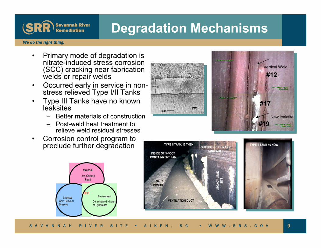
• Primary mode of degradation is nitrate-induced stress corrosion (SCC) cracking near fabrication welds or repair welds
• Occurred early in service in non-stress relieved Type I/II Tanks
• Type III Tanks have no known leaksites
– Better materials of construction– Post-weld heat treatment to
relieve weld residual stresses• Corrosion control program to
preclude further degradation
MaterialMaterial
Low Carbon Low Carbon SteelSteel
StressesStressesWeld Residual Weld Residual StressesStresses
EnvironmentEnvironment
Concentrated Nitrates Concentrated Nitrates or Hydroxidesor Hydroxides
SCC
OUTSIDE OF PRIMARY TANK WALLINSIDE OF 5-FOOT
CONTAINMENT PAN
LEGA
CY L
EAK
SITESALT
DEPOSITS
VENTILATION DUCT
TYPE II TANK 16 THENTYPE II TANK 16 THEN
#12
#17
#19
Vertical Weld
New leaksite
TYPE II TANK 16 NOWTYPE II TANK 16 NOW
10
Corrosion Control Program
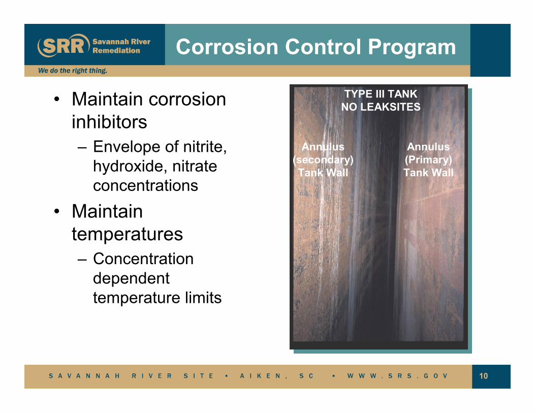
• Maintain corrosion inhibitors– Envelope of nitrite,
hydroxide, nitrate concentrations
• Maintain temperatures– Concentration
dependent temperature limits
Annulus(secondary)Tank Wall
Annulus(Primary)Tank Wall
TYPE III TANKNO LEAKSITES
11
Comprehensive Inspection Program
• Visual Surveillance– Still photography – ( ~5000 photos/year)– Wide Angle– Direct– Video Camera Inspections (over ~1000
video/visual exams/year)• In-Service Inspection Program
– NDE inspections included remote automated ultrasonic (AUT) inspection supplemented by remote visual inspection.

12
Comprehensive Inspection Program
• Type I/II tanks– No active leaksites– Use of conductivity probes in annulus– Routine visual inspections of annulus– Monitor and visually inspect during waste
removal activities• Type III/IIIA tanks
– Comprehensive visual inspection program– Comprehensive volumetric inspection
program

13
Visual Inspections
• Visual evidence of changes in tank component appearance– Leak sites– Corrosion– Abnormal conditions

14
Ultrasonic Inspections
• Historical Volumetric Wall Measurements
– Data collection initiated in 1967– Collected over 24,000 spot
measurements thru 1985
• NEW PROGRAM 1st CYCLE COMPLETED
• All 27 Type III tanks inspected with new program
• Examinations look for wall thinning, pitting, and Stress Corrosion Cracking
• Type II Tank 15 inspected twice• Inspect primary and secondary walls• Formal methodology for disposition of
results
• Access thru small-diameter riser
• On-board cameras

15
Ultrasonic Inspection of a Tank
1 1
2
3
4
(4 Strips)
Probe travels over 1 mile during a tank inspection

16
1st Cycle Baseline Data
• Consistent with understanding of waste chemistry and known mechanisms
• One-riser inspections as likely to find pitting as four-riser inspections
• No reportable, service induced indications (i.e., wall thinning, pitting, or cracking) on the primary tank wall.
• Revealed incipient pitting and non-reportable indications on the interior of the few primary tank walls.
– Most are pre-service• Revealed reportable wall
thickness and locally thin areas on the secondary wall and floor.
Tank #
Inspection Year (FY) / Inspection Type *
Incipient PittingIndications Comments
25 2004 / AOne 0.35” diameter pit 0.036” deep.
Isolated, broad shallow pitting
29 2006 / FS
Four 0.5” diameter pits 0.019 – 0.065” deep
Isolated, broad shallow pitting
31 2003 / AOne ~0.37” diameter pit 0.046” deep
Isolated, broad shallow pitting
32 2003 / FS
Three pits, max 0.75” diameter and 0.055” deep
Isolated, broad shallow pitting.
49 2005 / A
A band of pitting ~85 to 114 inches tank elevation. Up to 0.75” diameter and 0.040” deep. Broad shallow pitting
* FS = Full Scope A= Augmented

17
Tank 492004
Baseline Data: Incipient Pitting Definition
• Incipient pitting is a term used to describe small pit-like indications prior to them becoming reportable or actionable
• The term describes a shallow indication
• The term does not necessarily imply that the pit has recently developed or that it is still growing
• Many incipient pits may have developed pre-service

18
2nd Cycle ISI Plan
• Revised SRS ISI Program for waste tanks inspects all 27 Type III/IIIA tanks– Incipient interior tank wall indications– Wall thickness of secondary– Knuckle region in select tanks– High stress region: Tank 50
• Frequency– All 27 type III/IIIA tanks shall be inspected every 6-10 years – Tank 15 shall be inspected seven years after the most recent
inspection– A formal review of the ISI program shall be performed every
three years• Acceptance Criteria outlines actions in response to
indications consistent with national “Tank Structural Integrity Panel” recommendations

19
2009 Tank 29 Inspection
• Special inspection performed on Tank 29 to confirm assumption of circumferential uniformity of service-induced pitting
• One-strip inspection covers all historical interfaces (e.g., liquid-air) known to be the highest risk areas for corrosion
• Tank 29 inspected through all accessible risers (16) to provide the rigorous technical bases prior to launching of the next cycle of inspections

20
Summary
• The structural integrity program for the SRS tanks has over 50 years of successful operation
• Program aggressively addresses emerging issues
• Program proactively evolves in support of mission goals
• Technology-based evolution of programs•• POISED TO SUPPORT THE FUTUREPOISED TO SUPPORT THE FUTURE

21
• Questions?