Bye, Bye Supernova Nebulas Black Holes Stars By Grant and Nicholas Rockets are awesome!

thecambook
wild country
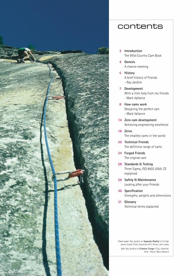
3 IntroductionThe Wild Country Cam Book
4 GenesisA chance meeting
5 HistoryA brief history of Friends - Ray Jardine
7 DevelopmentWith a little help from my friends - Mark Vallance
8 How cams workDesigning the perfect cam- Mark Vallance
14 Zero cam developmentAchieving engineering excellence
16 ZerosThe smallest cams in the world
20 Technical FriendsThe definitive range of cams
24 Forged FriendsThe original cam
28 Standards & TestingThree Sigma, ISO 9002 UIAA, CE explained
29 Safety & Maintenance Looking after your Friends
30 SpecificationStrengths, weights and dimensions
31 GlossaryTechnical terms explained
Front cover: Ray Jardine on Separate Reality 5.11d highabove Cookie Cliffs, Yosemite,1977. Photo: John Lakey
Left: Ray Jardine on Crimson Cringe 5.12a, Yosemite,1975. Photo: Mark Vallance
contents

‘Cams can’t work, put a nut in, it’s stronger’, ‘they won’t grip inLimestone’, ‘you can’tuse rigid ones inhorizontal cracks’,‘these are lighter butthose have morerange’, ‘just how dothey work anyway?’There has always been a special buzzabout Friends. More than any otherpiece of climbing gear Friends havealways created and polarised opinion.Every climber has a question and apoint of view and over the years their counter–intuitive nature andcomplicated physics has perplexedand excited climbers’ in equalmeasure.
Guide books describe cracks by Friendsize and climbers stories of life savingFriend placements are legendary. They are quite simply the mostimportant, the most expensive andthe most desired piece of gear on any climber’s rack.
Yet paradoxically, when polled,climbers still don’t seem to trustthem absolutely. Most would preferto set off on a lonely run-out pitchabove a ‘bomber nut’ than trust to itscomplicated mechanical equivalent.
So why should this beautifully
engineered machine, thatrevolutionised climbing world-wideover two decades ago be viewed withsuch ambivalence? The simple answeris that many climbers just don’t getthem. Why do these 21 componentsmade from exotic aluminium alloyand carbon steel, grip tenaciously inthe crack as we fall past, protectingus from certain disaster? Where didthey come from, who invented them,how do they work?
The Wild Country Cam Book will notonly explain why Friends work buthow they work, where they workbest, as well as the circumstanceswhere they may not work. Based onover two decades of experience inFriend manufacture, Wild Countryknows more about cams than anyother company and is best placed togive you the answers to thequestions you most wanted to ask.
Learn about the design of Friendsfrom prototype to production, thematerials and manufacturingtechniques, the quality control, thestandards and the testing involved.
Learn how a cam works, what is camangle, cam range, predictability andstability, friction and flares.
Learn about using Friends safely inparallel, flared and horizontal cracksand how to select the best Friend forthe job, Forged, Technical or the newZero cams.
The Wild Country Cam Book has beenwritten to answer all your questionsabout cams, but one question youmay quite rightly ask is why now?The answer is quite simply ZeroCams. This project more than anyother focussed us on explaining moreabout what we do, as we struggledwith the complexities of moving thegame on in cam design. We had tore-evaluate our ideas and techniques
and most importantly, we had toreinvent how we tested and usethese radical miniature cams outthere on the crag.
The Zero cam was the catalyst butThe Cam Book became much morefor us. The desire to write down thedistillation of 25 years of knowledgefor climbers to learn and understandabout cams became compelling. So whether you are an experiencedbig wall climber or fresh apprenticestraight from the gym, we trust you will enjoy the Wild Country Cam Book, brought to you by TheCam Company.
Martin Atkinson, Wild Country
THE CAM COMPANY 3
introduction> the wild country cam book
Above: Andy Cave testing Zeros on Cerro Mascara,Bader Valley, Paine, Patagonia. Photo: Simon Nadin

4 THE CAM COMPANY
Scott Burke on 33rd pitch of Freerider, (left of the Salathé Headwall a 5.10offwidth) Freerider is 37 pitches of 12d/13a. Photo: Eric Perlman
genesis> a chance meeting
The beginning of the Wild Country story
was a chance meeting between two
climbers from entirely different
backgrounds, Ray Jardine and Mark
Vallance. Had that meeting not taken
place, who is to say if camming devices
would have ever graced our hardware
racks. Of course most people would say
that someone else would have invented
them, but these things are always easy
with hindsight. I would prefer to believe
that if these two climbers, one a
scientist and the other an entrepreneur,
had not teamed up to climb together in
the summer of 1972, ‘Friends’ might
never have been.
Ray grew up in Colorado Springs, a
normal upbringing which included many
outdoor activities but remarkably no
climbing. In 1962 he decided that
aerospace engineering was the career
for him and set about his studies with a
will. It was while on a summer vacation
job in Yellowstone Park that Ray took
climbing lessons with instructor Barry
Corbet of Everest fame. The die was cast
and Ray threw himself into his new
passion, climbing many routes in the
Tetons that year.
By 1964 he had moved on to Northrop
University, Los Angeles, to study
Aeronautical and Astronautical
Engineering, qualifying in 1967 with a
degree in his chosen speciality. Moving
to Denver he began work as a systems
analyst, specialising in computer
simulated space flight, shaping
trajectories for earth satellite and
interplanetary missions.
Through the late 60’s climbing took
on more urgency for Ray. By 1970 he
decided to give up the space race and
began climbing full time, with Yosemite
occupying his ambitions. It was
undoubtedly during this frenzy of
climbing activity that culminated with
his first ascent of the Nose on El
Capitan, that his need to protect those
soaring crack lines developed. The next
two years saw the grades escalate and
by the end of 1972 he had climbed his
first 5.11 New Dimensions, which was
the first all nut ascent. Clean ‘pin free’
climbing was introduced to America by
Yvon Chouinard in the 60’s, and as Ray
pushed the grades ever higher, the need
for a new fast method to protect his
ambitious projects became obvious. The
Friend was born.
Ray had begun to work on his first
prototype Friend in 1971 and during the
following five years both his climbing
career and Friend development
accelerated at an extraordinary pace.
During 1976 and 1977 Ray’s investment
in climbing was paying off, even though
his other passion, Friends, had yet to
become a commercial reality. His
success on Routes like Crimson Cringe
5.12, Hangdog Flyer 5.12c, Separate
Reality 5.12, Owl Roof 5.12c, Rostrum
5.12c and the first 5.13 in the valley,
Phoenix, were not only due to his
outstanding climbing ability but
undoubtedly the success of his early
prototype Friends.
During the summer of 1972 Ray had
met and climbed with fellow instructor
and future business partner Mark
Vallance at the Colorado Outward
Bound School, although at this time
Ray’s early prototypes were still top
secret. It was much later, in 1975, that
Ray introduced his prototype cams to
Mark, a story told later in The Cam Book,
securing a future for what was to
become the first commercial camming
device, the Friend.
In 1977, after many frustrating attempts
to get his Friends made in the USA, Ray
teamed up with Mark Vallance to develop
and produce Friends in Derbyshire,
England. The story of that beginning, the
risks, the commitment, the facts, the
myths and the characters that made it all
possible is now told by these two
remarkable men.
Steve Foster, Wild Country

Some day we climbers may wear special
gloves and shoes enabling us to scale
blank walls like spiders. Should we fall
off, like spiders our body harnesses may
instantly attach safety lines to the rock.
If and when inventors develop this
technology, we will no doubt consider it
clever… but obvious – thanks to our
20-20 hindsight. But for now, none
of us can envision the details.
And so it was with the Friends 25
years ago when I was inventing
them. The need was apparent, at
least to me, but the actual
configuration was elusive to me
and everyone else.
Seeking a device that would anchor
itself in a crack, and hold with
greater power the harder the pull, I
began the inventive process in
1971 with a dual sliding wedge
design. Taking advantage of my
aerospace engineering background
I analyzed this configuration and
found it mathematically unsound.
The internal friction between any
kind of wedges reduce their
holding power and in many
situations such a device could pull
out. I was inventing for my own
use and was not about to
compromise safety.
The constant angle spiral is ubiquitous
in nature, from seashells and pinecones
to swirling barometric pressure gradients
and the great spiral nebulas. Really it is
just an expression of uniform growth.
Descartes described the principle
mathematically in 1638, calling it the
equiangular spiral. Since then constant
angle cams have been used in
uncountable mechanical devices.
Configuring a workable device, however,
proved to be an enormous task. In
retrospect it took someone with
aerospace engineering skills, a questing
mind coupled with extreme motivation
and a passion for climbing – something
of a rare combination in those days
perhaps. For months I worked, building
camming prototypes, testing them at
the local crags and innovating design
improvements in the evenings at home.
In the end I filled a couple of sizable
boxes with discarded prototypes.
Then one day after
trying absolutely
everything I could
think of, and
continually
straining my mind
for ever more ideas,
the concept came to me of
a double set of opposing and
independently spring loaded cams. Like
wheels of a car having independent
suspension, each of these cams would
be able to adjust to widely varying
surface irregularities, within its limit of
course. I put one of these ‘quads’
together and took it to the crags for
testing. The cams were spring-loaded
against each other, and they were held
together with a high-tensile steel bolt.
But the bolt was wrapped with a piece
of ordinary strap iron as a stem, and of
course the device lacked any kind of
trigger.
On a 5.8 route which I called Fantasia
located at Split Rocks, I climbed to a
stance where I could almost let go
with both hands, I managed to
squiggle the quad into a handsized
crack. By the way it behaved I knew
instantly that it was the answer.
The following spring, 1974, I took
my first set of working prototype
Friends to Yosemite and climbed
dozens of difficult routes with
them. These units were rough hewn
and extremely limited by today’s
standards, and I had only a limited
number of them: four size 21/2s
and three 31/2s. But they certainly
proved their worth, and at season’s
end three of us used them in an
attempt to climb the Nose in a day.
Three hours of late afternoon
downpour immobilised us beneath
the Great Roof and forced a bivy
at Camp V. But we did finish
in 20 hours total climbing
time, and managed to cut
the previous three-day
record in half.
In 1977 Mark Vallance
invited me to the UK
to help him start
manufacturing Friends.
Mark is a highly
dedicated and gifted individual, and
was the first person to see the
widespread appeal of Friends. Friend
marketability is obvious now, but it
certainly was not then, and Mark was
the visionary who made it happen.
The next year, Mark founded Wild
Country and started selling Friends.
Ray Jardine – 19 April, 1998.
THE CAM COMPANY 5
history> a brief history of friends
Above Top: Ray Jardine nesting on Eagle Ledge, the Nose El Capitan circa 1980 Photo: Daniel BolsterAbove: First working prototype Friend with strap iron stem Photo: Ray Jardine


THE CAM COMPANY 7
development> with a little help from my friends
Starting a new business is like havingone hundred feet of rope out, norunners and 5.10 move in front of you, and it can feel like that forweeks on end.
I prepared to jump, the weather wasperfect, clear sky, hard frost and ascattering of snow. The camera teamwas in position and waiting, the‘radio mike’ was turned on andrecording.
I climbed past the top Friend, got myfeet above it, climbed a little higher – ‘Hell I’ll give them a real show’ – andclimbed a little higher still. Then Ijumped.
As the rope tightened, my belayerwas jerked upwards and I felt mybreath being knocked out of me. Iwas lowered to the ground – noneed for a ‘retake’. The five minuteepisode on the BBC’s Tomorrow’sWorld programme was aired at theend of January 1978 and a six yearsecret was out of the bag.
It was 1972 when I first met RayJardine in Colorado, I was on my wayback from Antarctica. We were bothworking for Outward Bound andbetween courses climbed together.Though I did not know it then, hewas carrying the first prototypeFriend around with him – four camson a shaft with no stem or trigger. It required four hands to get it outof a crack.
My first experience of Friends wasmuch later, in 1975. Ray was verysecretive. He was carrying a blue nylonbag around which clinked and rattled.It was another hot October day. Wewere below Washington Column,about to make the first ascent ofPower Failure. I was sworn to secrecybefore the blue bag was opened andI was allowed to see its contents.
Ray’s prototypes were an oddselection. Some of them were
beautifully made with polishedaluminium, carefully filed edges,sophisticated trigger assembly andeven ‘J slots’ for holding the triggerin the closed position for neatnessand fast action. Others were gnarledand bent from use and testing, orjust slung together to try out somenew idea, but retained in thearmoury because they worked.
The name ‘friends’ was coined byChris Walker when he and Ray wereabout to go climbing with severalclimbers who were not in on thesecret. Chris wanted to know if Rayhad the bag of goodies, but didn’tknow how to ask without giving thegame away. Finally he said, “haveyou got the bag of Friends, Ray?”.The name stuck.
After several disappointments Rayasked me to make Friends inEngland. Much of the work we didtogether over the summer of 1977came to nothing. We could not findanyone to extrude the 7075 stemalloy. Everything was too expensive.A simple nut with one blob ofaluminium, two drilled holes, a singlepiece of wire and a swage cost undertwo pounds (1977). How could Imake a piece of kit with twentyseven high tolerance parts and awhole stack of holes and operations,and get it into the shops at a halfway realistic price?
When Ray left for California inSeptember he must have thoughtthat yet another attempt to getFriends off the ground had failed,but a few weeks later everythingstarted to fall into place. Now I hadto go for it, the long unprotectedlead. I borrowed all the money Icould and got the bank to give me a second mortgage on my house. I had some stationery printed andstarted to place orders for tools andcomponents. Finally, in November, I took a deep breath and gave up my job – no runners on this climb –either success, or a big, big fall.
Mark Vallance
Extract from an article published in
the 1978 Climber’s Club Journal.
I prepared to jump, the
weather was perfect,
clear sky, hard frost and
a scattering of snow.
Left: Ray Jardine making the first ascent in 1977 of Phoenix 5.13a, Yosemite USA Photo: George MeyersRight: Mark Vallance on Left Unconquerable, E1 5b, Stanage, Peak District, England 1979 Photo: Pete Freeman
8 THE CAM COMPANY
how cams work> designing the perfect cam
Keith Pike on El Matador 5.11a on Devils Tower, Wyoming, USA. Photo: Brian Bailey
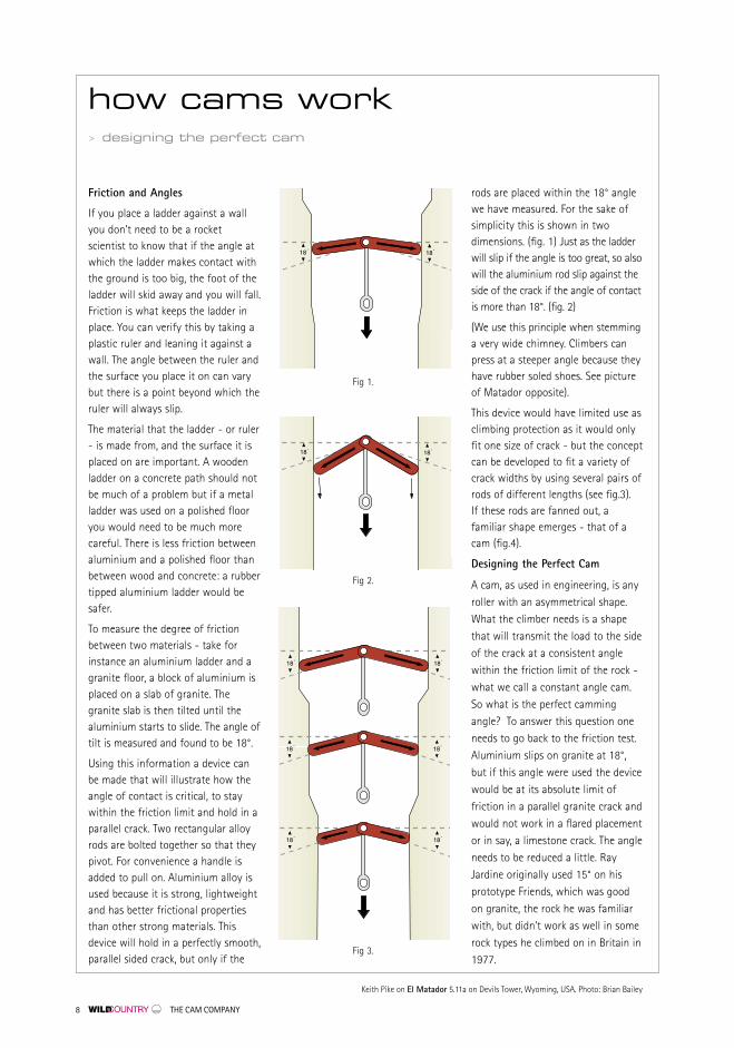
Friction and Angles
If you place a ladder against a wallyou don’t need to be a rocketscientist to know that if the angle atwhich the ladder makes contact withthe ground is too big, the foot of theladder will skid away and you will fall.Friction is what keeps the ladder inplace. You can verify this by taking aplastic ruler and leaning it against awall. The angle between the ruler andthe surface you place it on can varybut there is a point beyond which theruler will always slip.
The material that the ladder - or ruler- is made from, and the surface it isplaced on are important. A woodenladder on a concrete path should notbe much of a problem but if a metalladder was used on a polished flooryou would need to be much morecareful. There is less friction betweenaluminium and a polished floor thanbetween wood and concrete: a rubbertipped aluminium ladder would besafer.
To measure the degree of frictionbetween two materials - take forinstance an aluminium ladder and agranite floor, a block of aluminium isplaced on a slab of granite. Thegranite slab is then tilted until thealuminium starts to slide. The angle oftilt is measured and found to be 18°.
Using this information a device canbe made that will illustrate how theangle of contact is critical, to staywithin the friction limit and hold in aparallel crack. Two rectangular alloyrods are bolted together so that theypivot. For convenience a handle isadded to pull on. Aluminium alloy isused because it is strong, lightweightand has better frictional propertiesthan other strong materials. Thisdevice will hold in a perfectly smooth,parallel sided crack, but only if the
rods are placed within the 18° anglewe have measured. For the sake ofsimplicity this is shown in twodimensions. (fig. 1) Just as the ladderwill slip if the angle is too great, so alsowill the aluminium rod slip against theside of the crack if the angle of contactis more than 18°. (fig. 2)
(We use this principle when stemminga very wide chimney. Climbers canpress at a steeper angle because theyhave rubber soled shoes. See pictureof Matador opposite).
This device would have limited use asclimbing protection as it would onlyfit one size of crack - but the conceptcan be developed to fit a variety ofcrack widths by using several pairs ofrods of different lengths (see fig.3). If these rods are fanned out, afamiliar shape emerges - that of acam (fig.4).
Designing the Perfect Cam
A cam, as used in engineering, is any
roller with an asymmetrical shape.
What the climber needs is a shape
that will transmit the load to the side
of the crack at a consistent angle
within the friction limit of the rock -
what we call a constant angle cam.
So what is the perfect camming
angle? To answer this question one
needs to go back to the friction test.
Aluminium slips on granite at 18°,
but if this angle were used the device
would be at its absolute limit of
friction in a parallel granite crack and
would not work in a flared placement
or in say, a limestone crack. The angle
needs to be reduced a little. Ray
Jardine originally used 15° on his
prototype Friends, which was good
on granite, the rock he was familiar
with, but didn’t work as well in some
rock types he climbed on in Britain in
1977.
Fig 1.
Fig 2.
Fig 3.


THE CAM COMPANY 11
After much testing, Ray and WildCountry decided on 13.75° (see fig.5),an angle that worked well on mostrock types and allowed for use inquite flared cracks, in such rock asgranite and gritstone. Wild Countryhas never needed to change thisangle, which has becomeinternationally acknowledged as thedefinitive camming angle.
Stability
Having designed the perfect cam weneed to make a workable piece ofprotection. A device using twoconstant angle cams rather than thetwo rods as used in the first prototypewould still be very unstable. Friendshave four cams, which offer muchgreater stability in the same way asfour wheels is more stable than threewheels on a car. The width betweenthe cams also plays a key role in thisstability - compare a wide sports carwith a narrow van, which is morelikely to topple over. Therefore as partof the design of Friends the camspacing increases proportionatelywith the cam size, ensuring maximumstability throughout the range ofsizes.
Plane of rotation
As the cams rotate about the axle(known as the plane of rotation) theforce that they transmit to the sidesof the crack is directional. Friendsshould be placed - whenever possible- so that the stem is aligned in thedirection of the anticipated load fromthe falling climber and directing thestem downwards generally worksbest. This is not always possible, andsometimes the fall may not load thecams in a downwards direction, butthe single stem is designed to allowthe unit to swivel and align itselfcorrectly in most circumstances (seefig.6). If the load is not applied in the
plane of rotation - the cams can slipsideways. Remember the ladder. Ifyou present the ladder other than ata right angle to the house it will beunstable and can slip sideways asyou climb up it.
Walking
If you place a Friend in a smoothsided crack and move the stem, onepair of cams will grab the sides ofthe crack whilst the second pair willslide deeper into the crack. If thestem is moved in the oppositedirection the second pair of cams willgrab, and the first pair slide in deeper(fig. 7). This is called walking and cancause a cam to move into aplacement that is less safe - possiblymaking it move to a wider part of thecrack where the cams no longerwork. Because rope movement andrope drag can cause the Friend tomove we use strong springs to helpto keep the unit in the position theleader intended. Sometimes the tiringleader may curse the designspecification but the springs havebeen carefully developed to providethe maximum placement stability.
Flared cracks
To go back to the friction test again,the same result would be obtained ifa block of alloy the size of a sugarcube or a block weighing two tonswere used. The angle at which theblock will start to slip is independentof the load applied. What this meansin practice is that if you place a camin a flare and pull on it, and it doesnot come out, (and so long as you donot disturb the placement), the camwill hold up to the limit of the unitor the rock. To fully appreciate this,think back to the ladder. If theground where the ladder was placedsloped down hill there would still bea spot where the ladder would hold
Mark Vallance looking lean after success on Shishapangma in 1990 on Antenna E4 6a, Cornwall, England.Photo: Steve Foxley. Stefan Glowacz high on the first ascent of Odyssee 2000, (9-), Polar Bear Spire, BaffinIsland, Canada. Access to the route was by kayaking through arctic waters. Photo: Gerhard Heidorn
Fig 4.
Fig 5.
how cams work> designing the perfect cam

Mike Weeks, Man From Uncle (E6 6b), Pembroke,Wales, UK. Photo: Simon Carter, Onsight Photography.
Airlie Anderson on a one day ascent of Zodiac 5.10 A3, El Capitan, Yosemite. Photo: Ian Parnell
and beyond which the foot of theladder would slip. As the angle atwhich the ground slopes increases,there will come a point at which theladder will never hold. The same istrue of flared cracks. Depending onthe type of rock there will be an angleof flair in which the Friend will neverhold.
Getting them out
We’ve all done it; crammed in a unitin desperation knowing it will be areal nightmare for the second. Whenleading, try not to place them incracks that are too tight. Whenseconding, assess the placementbefore doing anything - you mightsave yourself a lot of trouble. If itlooks or feels as though it’s stuck,squeeze the trigger as hard as youcan before trying to remove the cam.If this does not work and the unitseems well and truly stuck, ask for atight rope and/or clip into anotherpiece so that you can use both hands,or if on a shorter climb, rappel down
how cams work> designing the perfect cam
later. Concentrate on one pair ofcams at a time and try to feel or seeif there is any movement. The floatingtrigger design of Friends will enableyou to do this as it allows themanipulation of individual pairs ofcams on either side of the axle. Tryusing a nut key to free the cams. Usea pair of wires looped round thetrigger to pull on the trigger barwhilst pressing or tapping the end ofthe stem to release the cams. Trymoving or tapping the cams sideways- in the direction the axle is pointing.Don’t get angry and don’t give up,most cams can be removed withpatience.
Conclusion
Climbers develop skills in seeingopportunities for placing nuts andthe same is true of camming units.Whilst these skills overlap, they aredistinct. Some climbers can makegreat nut placements but, usuallybecause they don’t fully understandthem, are less successful at placing
Fig 6.
Fig 7.
1
2
3
camming units. Selecting the rightsize of unit first time requiresexperience and using them is a skilland as such needs to be learnt andpractised. Your safety is enhanced bythis skill.
Understanding how cams work, thedesign parameters and the limitationof friction, cam angle and rock typewill help to increase your safetyfurther. As with all climbing gear,when the chips are down, a marginalplacement made with a completeunderstanding of the dynamics ofcam design is better than noplacement and informed andintelligent misuse of your equipmentis better than having no gear at all.
Mark Vallance


14 THE CAM COMPANY
Right: Andy Cave on Janus, E6 6b, Curbar Edge, Derbyshire. Photo: J Houlihan, Witness
Wild Country has always madeproducts that are relevant to theclimbing standards of the day andwhat grabbed our attention was therapid development of ‘clean aid’,‘speed’ and the ‘big free’ ascents bythe Huber brothers, Leo Houldingand others.
Smaller cams had proved invaluablefor these routes, but as weexperimented with our own smallcam designs we saw there was aproblem to be solved.Axle/termination design basicallyhadn’t changed for 20 years andremained a barrier to theminiaturisation necessary to takecams on to the next level - realmicro sizes.
Traditional cam design had beenrestricted by the need to achieve themaximum strength possible to meetinternational standards. We neededto go back to basics, so we askedclimbers to build a wish list fromtheir perspective of cutting edgeperformance. During theseconversations it was size, weight,and flexibility that were the keyelements, while interestingly,strength seemed to matter less aslong as they were, in climberparlance, ‘strong enough’.
Our engineers provided a solution. Their ‘Direct Loading Axle’ removedthe weight and especially bulk of theold axle/termination design, allowinga much smaller cam-head to beused. A ‘Flexistem’ protected thevery light wire rope needed for such
tiny units whilst a ‘Guided TriggerSystem’ allowed confident triggeringwith minimal flex, essential forplacement and removal.
Strength
While every effort was made tomake Zeros as strong as possible,the radical design limited theamount of strength that we couldbuild into them, especially in thesmaller sizes. Zeros 1 and 2 whichare rated as ‘Progression Equipment’and cannot therefore berecommended for free climbing’.However similar criteria are appliedto test small nuts for example RPs.Yet these are used extensively forfree climbing and are essentialcomponents of any rack.
Zeros 1 and 2 were designedprimarily to extend an aid climbersrack but with a distinct nod to thefree climber and it is quite clear thatthey will perform the same role asthe RPs described above.
Function
We soon came to understand thatthese units were a step forward inour understanding of camperformance. As with any new device there was aperiod of adjustment, getting usedto the new techniques necessary toachieve the best results. From ourtesting it became obvious that Zerosunlike larger cams, needed adifferent approach.
We found it easier to place Zerosfrom a static position for example in‘aiders’, than in the middle of adynamic free climbing move, andthe more gently the cams are pulledback the easier they were to place,more like precisely placing a micronut than a cam.
Depth of Placement
Due to the small expansion range,we found it advisable to place Zerosso that we could view all the camsto make sure they were seated well.Even relatively smooth rock, has anirregular surface which can allowthe cams to expand out of range.Obviously the deeper the placementthe less visible the unit and thegreater the possibility the camsover- expanding.
Camstops
Zero cams are the first micro camsto have cam stops rated to thestrength of the unit. During testingwe found that they performed animportant role in anchoring the unitin extreme direct aid placements. We do not recommended that this isthe first choice of placement andshould only be undertaken byexperienced aid climbers.
Conclusion
We are now sure, Zeros are ‘clever’enough and strong enough tosatisfy what cutting edge climbersdemanded, the ultimate tool in theirquest for more and more extremeadventures.
Richie Patterson, Wild Country
zero cam development> achieving engineering excellence


16 THE CAM COMPANY
SizeNew Zeros take cam sizes smallerthan has ever been possible. Six sizesstart at a minuscule 0.22" (5.5mm).This ultra-small cam dimension isachieved by using a new, compact,patent pending Direct Loading Axle™which amalgamates termination andaxle into one unit, allowing the camsto operate without the hindrance ofbulky conventional assembly.
FlexibilityNew technology was developed toprovide climbers with total stem
"New products appear from time to
time that make routes easier and
sometimes people claim these
advances warrant grade revisions.
After testing Zeros I know these
claims are for real, Zeros will do
much more than we can yet
imagine. Speed times will shrink and
grades really will need adjustment.
These are the indispensible granite
tools for the 21st century."
Kevin Thaw
Russel S. Mitrovitch climbing The Joshua Tower, Baffin Island, Canada. The big walls of Baffin Island offer serious and remote challenges to modern activists. Photo: Russel S. Mitrovitch collection
zeros> the smallest cams in the world
flexibility and complete control. This was achieved with a new, patentpending Flexistem™ system whichoverlays the wire rope stem. Thisallows flexibility up to the base of the cam-head, minimising thepossibility of levering the cams out of shallow seams.
ControlFlexibility is of limited use withoutcontrol, and the patent pendingGuided Trigger™ system achieves
positive directional control of thecams through an innovativecombination of flexible springs andguides which overlay the stainlesssteel wire rope stem. These prevent‘bowing’ as the trigger is retracted yet allow individual manipulation ofthe cams in restricted placements.

>1. Patent pending direct loadingaxle™ allows cams down to a crackwidth of 5.5mm (0.22 inches)
>2. Patent pending Flexi-stem™ systempermits the most extreme camplacements
>3. Patent pending Guided Trigger™system allows total control of thecam head.
>4. Six Sizes Z1 through Z6 arecolour coded and include newexclusive 10mm Dyneema™ double loop fast extending slings
>5. Incredibly light weight, the Zero One weighs a mere 1ozincluding sling, lighter than a wire-gate karabiner
Left: Zero One Actual Size
Above: Computer Aided Design (CAD)
enabled Wild Country to create
our unique direct loading axle™(Patent pending) made from 4340
Nicromo steel and using Nickel plating
to protect against corrosion.
VersatilityTo complete the design of theseexceptional micro-cams, They weresubjected to a rigorous test regime.Zeros are small, but not too small forthe beefy, taped hands of a crack-climber. Zeros are colour coded forfumble-free racking. Finally, Zeros arefitted with an ultra-light colour-coded 10mm Dyneema™ sling whichis bar-tacked in a double loop for fastextending when required.
LightnessThese new technologies, reducingcomponents, re-evaluating and goingbeyond the boundaries of currentcamming technology, have created arange of cams which are lighter andmore compact than anythingpreviously imagined. Sizes Z1 throughZ3 are all lighter than most standard’biners’. The complete set (6 pieces) weighs 9.5oz
(268gm) – little more than a single
Technical Friend 4.
2
3
4
1
5

18 THE CAM COMPANY
Because Zero cams are different, it is vitally important that you readand understand the instructionssupplied with each cam.
Not all sizes of Zero cams complywith EN12276 and are thereforeclassed as progression equipment.Progression equipment must only be used for direct aid, this means it must only be subjected to static
loads not exceeding the strength as marked on the device. See specification chart for completedetails.
Zero cams may be damaged in a fall or, in the case of progressionequipment, the axle may bend whenweighted with a static loadapproaching the rated strength, and consequently should always
be examined before re-use.
If your Zero Cam exhibits signs ofwear, defect, or bending, or if there is any doubt about its serviceability,replace it. It is recommended thatany equipment involved in a seriousfall or weighted sufficiently to causebending of the axle in the case of progression equipment, should be replaced.
Above: Dave Hesleden on Duncans Dyhedral attempting the first free ascent at E4 6a an800m route on Cerro Mascara, Bader Valley, Paine, Patagonia. Photo: Simon Nadin
zeros are different
Above: Z1 and Z2 are
shown at actual size

THE CAM COMPANY 19
dynamics
A General Placement: It is vitally
important that all the cams make
contact with the sides of the crack,
preferably in the middle 1/2 of their
expansion range (i.e. the cams should
be between 1/4 to 3/4 open) as the
minimum breaking strengths in
kilonewtons (kN) is tested at 1/2
expansion (refer to specification
chart on page 30).
You should note particularly that
when using Zeros rated as
progression equipment, their
expansion range is very small and
therefore the margin of error is
equally small. When placing
progression equipment inspect the
placement carefully to ensure that all
four cams are in contact with the
crack as stated above, paying
particular attention to the two rear
cams which will be difficult to see.
Avoid deep placements (particularly
Zero cams rated as progression
equipment) where setting and
retraction will be problematical.
B Maximum Strength: As a general
principle in order to obtain the
maximum strength from Zeros, they
should always be placed with the
stem in line with the anticipated
direction of loading. This will ensure
that the force of the fall will be
transmitted directly to the cams in
their plane of rotation and will avoid
adverse torsional forces on the stem
(see fig. B).
C Horizontal Placement: and
D Vertical Placement: Zero cams are
designed specifically to work in
extreme horizontal placements and
shallow vertical cracks. Flexibility to
the base of the cams means no
termination to lever out the
placement. But be aware these
extreme direct aid placements require
expert training and may only support
body weight.
Caution: When removing Zero cams
take care to avoid exerting excessive
force on the trigger mechanism, due
to the miniaturisation of the
components (particularly with Zeros
rated as progression equipment).
The trigger mechanisms are rated at
only 45kgs. You will find a gentle
approach when placing or retracting
Zeros reaps rewards in speed and
safety.
B
C
D
A
Above: Dave Hesleden on Cuernos Est, Bader Valley, Paine, Patagonia. Photo: Simon NadinBottom Right: Z2 in extreme vertical placement
20 THE CAM COMPANY
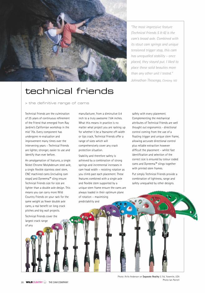
”The most impressive feature
(Technical Friends 5 & 6) is the
cam’s broad axle. Combined with
its stout cam springs and unique
tensioned trigger stop, this cam
has unequalled stability - once
placed, they stayed put. I liked to
place these solid beauties more
than any other unit I tested.“
Johnathan Thesenga, Climbing 183
Technical Friends are the culmination
of 25 years of continuous refinement
of the Friend that emerged from Ray
Jardine’s Californian workshop in the
mid ‘70s. Every component has
undergone re-evaluation and
improvement many times over the
intervening years – Technical Friends
are lighter, stronger, easier to use and
identify than ever before.
An amalgamation of features, a single
Nickel Chrome Molybdenum steel axle,
a single flexible stainless steel stem,
CNC machined cams (including cam
stops) and Dyneema™ sling ensure
Technical Friends size for size are
lighter than a double axle design. This
means you can carry more Wild
Country Friends on your rack for the
same weight as fewer double axle
cams, a real benefit on long crack
pitches and big wall projects.
Technical Friends cover the
largest crack range
of any
manufacturer, from a diminutive 0.4
inch to a truly awesome 7.64 inches.
What this means in practice is no
matter what project you are racking up
for whether it be a fearsome off-width
or tips crack, Technical Friends offer a
range of sizes which will
comprehensively cover any crack
protection situation.
Stability and therefore safety is
achieved by a combination of strong
springs and incremental increases in
cam head width – resisting rotation as
you climb past each placement. These
features combined with a single axle
and flexible stem supported by a
unique stem frame ensure the cams are
always loaded in their optimum plane
of rotation – maximising
predictability and
safety with every placement.
Complementing the mechanical
attributes of Technical Friends are well
thought out ergonomics - directional
control coming from the use of a
floating trigger and unique stem frame,
allowing accurate directional control
plus reliable extraction however
difficult the placement – whilst fast
identification and selection of the
correct size is ensured by colour coded
cams and Dyneema™ slings together
with printed stem frames.
Put simply Technical Friends provide a
combination of lightness, range and
safety unequalled by other designs.
technical friends> the definitive range of cams
Photo: Airlie Anderson on Separate Reality 5.11d, Yosemite, USA Photo: Ian Parnell

THE CAM COMPANY 21
>1. CNC machined cams with integralcam stops made from 7075 aircraftquality aluminium.
>2. Nickel Chrome Molybdenun steelaxle 85TPSI.
>3. Stainless steel axle nuts riveted fortotal security.
>4. Tuned springs resist ‘walking’ withoptimum trigger pressure.
>5. Stainless steel axle terminationswaged to wire rope with 45 tonpressure.
>6. 7x7 Stainless steel wire rope,flexible and corrosion resistant.
>7. Stainless steel sling terminationswaged to wire rope with 45 tonpressure.
>8. Impact modified temperaturetolerant nylon stem frame providesdirectional control and rigidity.
>9. Impact modified nylon trigger‘floats’ to minimise interferencefrom rope or rock.
>10. Flexible and light weight 7x7stainless steel trigger wiresconnect trigger to cams.
>11. Aluminium swage connects triggerwire to rigid L wire.
>12. Stainless steel L wire controls thecams and is recessed into the camproviding a snag free profile to thecam head.
Bottom Right: Detail of Technical Friends CNC machined cam stops which give passive strength shouldthe cams run out of expansion range in an inward flaring crack.
7
1
4
23
5
5
9
12
11
6
8
10


THE CAM COMPANY 23
Technical Friend 00,(Shown right atactual size)Minimum strength 10kN
A General Placement:Always ensure that all the camsmake contact with the sides ofthe crack, preferably in the middle1/2 of their expansion range (i.e.the cams should be between 1/4to 3/4 open). Always ensure thedirection of loading is in the planeof rotation of the cammingmechanism (see fig. A).
B Vertical Cracks:As a general principle, in order toobtain the maximum strengthfrom Friends they should alwaysbe placed with the stem in linewith the anticipated direction ofloading. This will ensure that theforce of the fall will be transmitteddirectly to the cams in their planeof rotation and will avoid adversetorsional forces on the stem (see fig. B).
C Horizontal Placement: Technical Friends may be loadedover an edge as long as the stemmakes contact with the edge in itsflexible section, however, this maycause damage to the cable (seefig. C).
D WARNING: The strength of Friends placed invertical (‘bottoming’) cracks whereit is impossible to align the stemin the direction of the anticipatedload will be seriouslycompromised (see fig. D).
Above: George Smith on Ugly, E7 6b/c, Trwyn y Tal, Lleyn Peninsula, Wales. Photo: Ray WoodLeft: Beth Rodden on Sphinx Crack, 5.13b/c, South Platte, Colorado Photo: Topher Donahue
A
B
C
D
dynamics

24 THE CAM COMPANY
Above: Chester Dreiman on Super Crack 5.10, Canyonlands Utah, circa 1986. Photo: Ed Webster
forged friends> the original cam
Forged Friends have evolved directlyfrom Ray Jardine’s visionary designwhich revolutionised the climbingworld back in 1978. Despite theirnew colour coded cams, Dyneema™slings, cam stops and forged stemsyou might wonder why rigid stemscontinue to be made alongsideflexible stem units. The answer isfourfold - price, weight, precisionand durability.
Undoubtedly a flexible stem can beplaced in horizontal cracks withoutworry but with a little preparation(see Gunk’s Tie-off fig E page 27)Forged Friends provide safehorizontal crack protection even inthe smaller sizes.
Experienced users of rigid stemFriends have also realised that thebigger sizes don’t need a tie off at all, as burying the stem in ahorizontal deep placement puts littlestrain on a Forged stem, only
exposing the very end to the force ofthe fall see figure A, page 27.
Another endearing feature of ForgedFriends is the control provided by a rigid stem, ensuring preciseplacement and easier retrieval due tothe direct transfer of the triggeringaction through to the cams. Theindependent control of each pair ofcams can be used to the full on rigidunits, allowing precise movements ofthe trigger to tease out even themost stubborn placement.
Don’t dismiss Forged stem Friends asoutdated - the benefits of thisoriginal design will impress you withtheir honest performance andpredictability.

THE CAM COMPANY 25
"I remember when Friends
appeared in the late 1970s. Back
then I climbed in EB rock shoes,
flared jeans and a tie dyed shirt,
and I drove a VW van. The shoes
and clothes wore out long ago
and the van broke down too. But
I’ve still got most of my original
Friends on my rack, 23 years later."
Greg Child
>1. The stems are forged into an ‘I’beam section increasing strengthwhilst reducing weight.
>2. Forged Friends feature colour codedcams with CNC machine integral camstops which give passive strengthshould the Friend ‘walk’ and the camsbecome fully opened in flaring cracks.
>3. The dedicated slings are made from12mm Dyneema™ and are colourmatched with the cams to aid fastidentification.
>4. Redesigned Cam profiles ensuretangle free racking on the biggest of big wall racks.
Below: Ray Jardine’s first working
prototype used in 1974 on a record one
and a half day ascent of the Nose with
Lou Dawson and Kris Walker. This early
Friend bears a remarkable resemblence
to the current design of Forged Friend
with the exception of the trigger lock
(later dropped from the design) and is
testimony to the integrity of his original
concept.
1
4
2
3
Above: Stefan Glowacz training on VW Bus, Smith Rocks, Oregon, USA. Photo: Uli Wiesmeier
THE CAM COMPANY 27
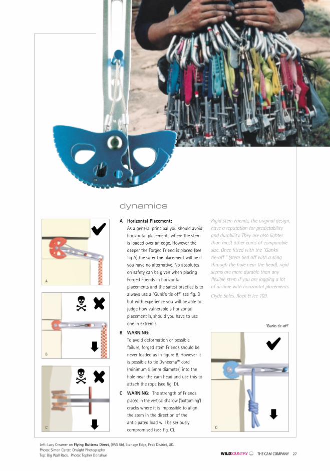
A Horizontal Placement:As a general principal you should avoid
horizontal placements where the stem
is loaded over an edge. However the
deeper the Forged Friend is placed (see
fig A) the safer the placement will be if
you have no alternative. No absolutes
on safety can be given when placing
Forged Friends in horizontal
placements and the safest practice is to
always use a "Gunk’s tie off" see fig. D
but with experience you will be able to
judge how vulnerable a horizontal
placement is, should you have to use
one in extremis.
B WARNING:To avoid deformation or possible
failure, forged stem Friends should be
never loaded as in figure B. However it
is possible to tie Dyneema™ cord
(minimum 5.5mm diameter) into the
hole near the cam head and use this to
attach the rope (see fig. D).
C WARNING: The strength of Friends
placed in the vertical shallow (‘bottoming’)
cracks where it is impossible to align
the stem in the direction of the
anticipated load will be seriously
compromised (see fig. C).
Rigid stem Friends, the original design,have a reputation for predictabilityand durability. They are also lighterthan most other cams of comparablesize. Once fitted with the “Gunks tie-off “ (stem tied off with a slingthrough the hole near the head), rigidstems are more durable than anyflexible stem if you are logging a lot of airtime with horizontal placements.
Clyde Soles, Rock & Ice 109.
dynamics
D
A
C
C
B
‘Gunks tie-off’
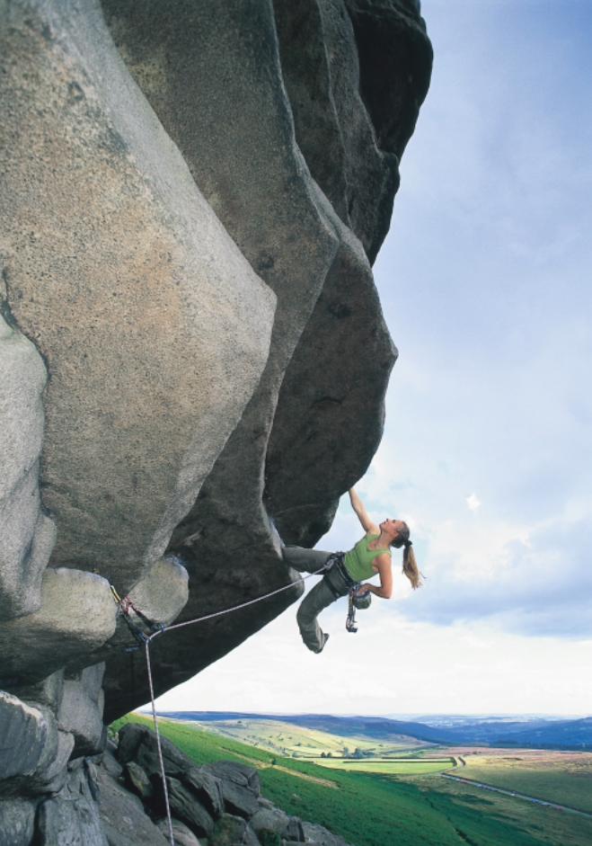
Left: Lucy Creamer on Flying Buttress Direct, (HVS 5b), Stanage Edge, Peak District, UK. Photo: Simon Carter, Onsight Photography.Top: Big Wall Rack. Photo: Topher Donahue

28 THE CAM COMPANY
3σσ – Three Sigma The Three Sigma Rating system is amethod of Statistical Quality Control (SQC)which we use to describe, analyse, andcontrol the rated strengths of ourproducts. For each batch produced, astatistically representative sample is takenand tested to destruction in accordancewith the relevant European Standard forthat product and/or our own approvedinternal Quality Assurance Procedures.
These procedures are an integral part ofour Quality Assurance System. From thedata obtained from destruction testing, theaverage (or mean) and sample standarddeviation (which is a measure of variancebased upon the results obtained) iscalculated. 3σ is three times the samplestandard deviation. When 3σ is deductedfrom the mean result obtained, we canpredict the spread of results which wouldbe obtained if we were to destroy theentire batch (which is why we sampleonly!). We monitor this data closely frombatch to batch to ensure that the ratedstrength (as marked on the product) isalways less than the mean minus threetimes the sample standard deviation. Thisensures that the minimum breakingstrength for all products is consistentlyhigher than the rated strength as markedon the product.
BS EN ISO9002 Quality Assured FirmWild Country is registered to InternationalStandard ISO 9002: 1994 (Certificate No.C/7545.Q/2678). This is the internationally-accepted model for Quality AssuranceManagement Systems, which has beenadopted in over 150 countries worldwide.
UIAA Standards The UIAA (International Union of AlpineAssociations) began the process offormulating standards for climbingand mountaineering equipment over3 decades ago. With the advent of thePPE (Personal Protective EquipmentDirective 89/686/EEC) in 1989 it appearedthat UIAA standards no longer had anyrelevance. However the UIAAhas continued to monitor and shadow EN standards and is currently formulatinga standard for belay devices which will indue course be adopted as an EN standard.
CE CertificationWhere required by law (European UnionDirective 89/686/EEC - for Personal Protective Equipment). Wild Country products are type examined,tested and certified (see EN12276 below).
The organisation responsible for ourISO 9002 Quality System and CE marking is Notified Body No. 0120 (SGS UK Ltd.Ellesmere Port, Cheshire, CH65 3EN).
European Standard EN 12276
5.1 Test methodsAt least two frictional anchors shall beprovided for each test. If a frictionalanchor is manufactured in different sizes,each size shall be tested.
5.2 Apparatus for strength test
5.2.1 Layout
The apparatus consists of two parallel,rigid steel supporting jaws for theadjustable parts of the frictional anchorand of a loading bar with a diameter of (10± 0.1) mm for the means of attachment,see figure 1.The static friction between the supportingjaws and the frictional anchor shall be
great enough to prevent the frictionalanchor from slipping through at the testload, but the maximal surface roughness
of Rmax shall no exceed 500µm. Thesurface of the loading bar shall have anarithmetical mean deviation of the profileof Rmax = 6,3 µm.
There are no surface roughness
requirements for the loading bar when
the means of attachment is other than
textile material.
5.2.2 Adjustment
The distances between the supporting jawsshall be according to the followingformula:
Position 1: s = bmin+[(bmax – bmin)/4]
Position 2: s = bmin+[(bmax – bmin) 3/4 ]
Where
bmin is the minimum adjustable width
bmax is the maximum adjustable width
If the range between bmax and bmin isless than 5mm only one position accordingto the following formula shall be adjusted:
S = bmin+[(bmax – bmin) /2]
standards and testing> wild country cams are tested to the most stringent
international standards
1. Loading Bar2. Supporting Jaws3. Frictional Anchor4. Means of Attachment
Fig. 1

SafetyThe safe working life of Wild CountryFriends may be as little as one use inextreme circumstances, therefore it isvitally important that you check yourFriends before each use. If any of thefollowing are detected you should retirethe Friend from use immediately and seekexpert advice.
a) Metal components: corrosion, burrs,cracks, distortion, broken or frayedcables, excessive wear, deformed stem.
b) Flexible stems: particularly check thatthe stem is straight and not sufferingfrom deformation, abrasion or brokenstrands of wire.
c) Textile slings: check for broken stitches,cut of worn threads.
TemperatureAlways keep products made wholly orpartially from textile elements below 50°Cas the performance of the Dyneema™ fromwhich they are made may be affected attemperatures above this. Tests down to-40°C show no permanent change inthe performance of this materialalthough it may stiffen while attemperatures below 0°C.
Sea WaterIt is essential that all Wild CountryFriends are cleaned as soon as it ispractical after exposure to sea wateror any saline environment (e.g. whenused on sea cliffs).
Chemicals and Corrosive ReagentsAvoid all contacts with chemicalreagents as they will affect theperformance of this product (e.gvehicle battery acid, bleach. etc).Discard any product immediately ifcontact has or is suspected to haveoccurred (the product maypermanently weaken without showingany signs).
MaintenanceWild Country Friends are not usermaintainable with the exception ofcleaning and lubrication (whererelevant).
Inspect your Friends for the following -they may require cleaning and lubricationas detailed below:
a) Ensure that the unit operates smoothlythroughout its complete range ofmovement.
b) Ensure that when the trigger is releasedfrom any position the cams instantlyreturn to their fully expanded position.
CleaningFirst rinse the Friend in clean cold water ofdomestic supply quality. If still soiled rinsein warm water (maximum temperature40˚C) with pure soap. Thoroughly rinse anddry naturally in a warm ventilated roomaway from direct heat.
LubricationThe camming mechanism must belubricated periodically and after anycleaning and drying process. This willensure smooth operation and resistance tocorrosion. A kerosene based lubricantshould be sprayed between the cams and
directed at the axle and springs.Operate the Friend several times toensure even penetration of thelubricant. Allow to drain and then
wipe off any surplus lubricant. Avoidcontamination of the Dyneema™ slingwith the lubricant. If this occurs referto cleaning.
StorageAfter any necessary cleaning andlubrication, store unpacked in a cool,dark, dry, ventilated place away fromsharp edges, pressure, corrosives or anypossible causes of damage. Wetequipment should first be allowed todry as detailed above.
ObsolescenceWild Country Friends will deteriorate
over time in the course of normal use
and because of this we are required by
directive 89/686/EEC to give a
obsolescence date. It is difficult to be
precise but a conservative estimate
for this product is that it has a life
span of ten years from the date of
first use for metal components or five
years from date
of first use or
ten years from
date of first
storage for textile
components.
However, please
note that the following
factors will further reduce
the safe working life:Metal Components: normal use, exposureto chemical reagents, heat contamination,high impact load or failure to maintain(clean/lubricate) as recommended. Seeabove.
Textile Components: most textile materialsused in safety equipment are known todegrade gradually with time, even whenstored in ideal conditions. Additionallynormal use, rope burn, exposure tochemical reagents, exposure to elevatedtemperatures, high impact load, prolongedexposure to UV light including sunlight,abrasion, cuts or failure to maintain (clean)as recommended will cause furtherreductions in strength. See above.
WarningIn accordance with EU Directive 89/686/EC WildCountry Ltd. supplies detailed instructions with allits products and recommends that the user readsand understands these instructions before use. If you are in doubt, require further advice orwould like a copy of the instructions for any WildCountry product, you should contact us at theaddress printed in this Cam Book. It is the user’sresponsibility at all times to ensure that he or sheunderstands the correct and safe use of anyequipment supplied by Wild Country Ltd., uses itonly for the purposes for which it is designed andpractises all proper safety procedures. Themanufacturer or supplier will not accept anyresponsibility for damage, injury or deathresulting from misuse.
THE CAM COMPANY 29
safety and maintenance> always read and understand the instructions
supplied with each product
Wild Country Ltd. Reserves the right to modify without notice the design and specifications of products described in this Cam Book.
All weights, volumes and sizing specifications, where quoted, are nominal.
Wild Country Ltd. All rights reserved © 2002
specification> strengths, weights and dimensions
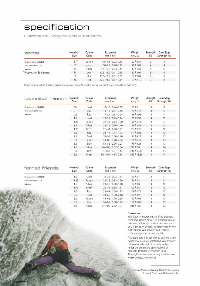
zeros Nominal Colour Expansion Weight Strength Cam StopSize Code mm / inch gm / oz kN Strength kN
Z1* purple 5.5-7.8 / 0.22-0.31 23 / 0.81 3 3Z2* green 7.0-9.8 / 0.28-0.39 29 / 1.02 4 4Z3 silver 8.5-12.2 / 0.33-0.48 43 / 1.51 6 6Z4 gold 10.3-16.0 / 0.41-0.63 50 / 1.94 6 6Z5 blue 13.0-19.0 / 0.51-0.75 57 / 2.01 9 9Z6 red 17.0-24.0 / 0.67-0.94 61 / 2.15 9 9
Patent pending. All sizes feature passive strength cam stops. All weights include dedicated colour coded Dyneema™ sling.
CE approved to EN12276
UIAA approved to 125
3σσ rated
*Progression Equipment
Nominal Colour Expansion Weight Strength Cam StopSize Code mm / inch gm / oz kN Strength kN
00 Gold 10–16 / 0.40–0.63 60 / 2 10 60 Blue 13–19 / 0.51–0.75 79 / 2.77 14 110.5 Red 17–24 / 0.67–0.94 85 / 2.98 14 111.0 Gold 19–29 / 0.75–1.14 95 / 3.33 14 111.25 Purple 21–33 / 0.83–1.30 98 / 3.43 14 111.5 Silver 23–35 / 0.90–1.40 98 / 3.43 14 121.75 Green 25–41 / 0.98–1.61 107 / 3.75 14 122.0 Red 29–44 / 1.14–1.73 111 / 3.89 14 122.5 Gold 33–55 / 1.30–2.16 122 / 4.27 14 123.0 Purple 43–66 / 1.70–2.60 155 / 5.43 14 133.5 Blue 51–82 / 2.00–3.23 178 / 6.23 14 134.0 Silver 64–100 / 2.52–3.94 217 / 7.6 14 145.0 Red 84–138 / 3.31–5.43 348 / 12.18 14 146.0 Green 118–194 / 4.64–7.64 533 / 18.66 14 14
technical friends
CE approved to EN12276
UIAA approved to 125
3σσ rated
Nominal Colour Expansion Weight Strength Cam StopSize Code mm / inch gm / oz kN Strength kN
1.0 Gold 19–29 / 0.75–1.14 89 / 3.1 14 111.25 Purple 21–33 / 0.83–1.30 94 / 3.3 14 111.5 Silver 23–35 / 0.90–1.40 94 / 3.3 14 121.75 Green 25–41 / 0.98–1.61 100 / 3.5 14 122.0 Red 29–44 / 1.14–1.73 106 / 3.71 14 122.5 Gold 33–55 / 1.30–2.16 120 / 4.2 14 123.0 Purple 43–66 / 1.70–2.60 143 / 5.01 14 133.5 Blue 51–82 / 2.00–3.23 168 / 5.88 14 134.0 Silver 64–100 / 2.52–3.94 216 / 7.56 14 13
forged friends
CE approved to EN12276
UIAA approved to 125
3σσ rated
GuaranteesWild Country guarantees all of its productsfrom new against defects in workmanship ormaterials, unless the product has been wornout, misused, or abused, as determined by ourexamination. Wild Country will repair orreplace any product as appropriate.
This guarantee is in addition to your statutoryrights which remain unaffected. Wild CountryLtd. reserves the right to modify withoutnotice the design and specifications ofproducts described in this Cam Book. All weights volumes and sizing specifications,where quoted, are nominal.
Left: Alan Mullen on Auricle, Grade VI, Cairngorms,Scotland. Photo: Alan Mullen collection

Left: Nathan Martin on Pitch 2, Six Star 5.13b, Indian Creek, Utah. Photo: Jay SmithRear cover: ‘Big Wall Hands’, circa 1987. Photo: Uli Wiesmeier
Axle: The steel rod about which the cams rotate. See page 21component 2.
Bar tack: High strength stitch pattern used to sew climbing tapetogether.
Cam Stop: The load bearing stop which prevents the cams from overrotating when a camming device runs out of expansion range.See page 21.
Camming angle: The angle at which the load is transmitted to the side of aparallel crack. See page 11 Fig 5.
CNC: Computer Numeric Control used to programme automaticmilling machines.
Coefficient of friction: The mathematical constant that defines the degree of frictionbetween any two surfaces.
Constant angle cam: A cam which maintains the same angle of contact with thecrack face throughout its expansion range. See page11 Fig 5.
Dyneema™: A high strength polyaramid fibre which is weight for weightstronger than steel.
Direction of loading: The way in which the force of a fall loads a camming device.See page11.
Expansion range: The distance between the opened and closed position of acamming device.
Flared crack: A rock crack which increases in size either inwards oroutwards.
Forging: The process of heating metal before shaping it by pressure orimpact. See page 25 fig.1.
Friend: The name given to the original camming device designed byRay Jardine and produced by Wild Country in 1977.
L wire: The L shaped rigid wire used to connect the cam to thetrigger assembly. See page 21 component 12.
Patent: An official licence from a government granting a business thesole right, for a limited period, to make and sell a piece ofequipment.
Plane of rotation: The area within which the cams rotate at right anges to the axle.
Swage: The method of construction used to join the wire rope stemto the axle and sling terminations.
Stem: The component that connects the cam/axle assembly to thesling. See flexible stems page 21 and forged stems. See page 25 fig 1.
Springs: The components which push the cams into their fullyexpanded position thereby holding the cams against the crackwall. See page 21 component 4.
Stem frame: The component which supports the flexible stem providingdirectional control. See page 21 component 8.
SLCD: Acronym for ‘spring loaded camming device’ often used todescribe ‘Friends’. See above.
Termination: The component swaged (see above) to either end of a theflexible stem. See page 21 components 5&7.
Trigger: The bar which pulls the trigger wires which retract the cams.See page 21 component 9.
Trigger wire: Flexible wire which connects the L wire to the Trigger. See above and page 21 component 10.
Walking: Process whereby the camming device climbs deeper into acrack by reacting to rope movement. See page 12 figure 7.
Editor: Steve FosterDesign: vivid creative ltd. www.vividcreative.com
Thanks: Ray Jardine, Mark and Jan Vallance and Richie Patterson.
glossary> technical terms explained

Meverill Road, Tideswell, Buxton, Derbyshire, England SK17 8PY
T +44 (0) 1298 871010, F +44 (0) 1298 872077, E [email protected], W wildcountry.co.uk