In-Line Localized Monitoring of Catalyst Activity in Selective
12
Transcript of In-Line Localized Monitoring of Catalyst Activity in Selective

US 20090305425A1
(12) Patent Application Publication (10) Pub. No.: US 2009/0305425 A1 (19) United States
Muzio et al. (43) Pub. Date: Dec. 10, 2009
(54) IN-LINE LOCALIZED MONITORING OF CATALYST ACTIVITY IN SELECTIVE CATALYTIC NOX REDUCTION SYSTEMS
(75) Inventors: Lawrence J. Muzio, Laguna Niguel, CA (US); Randall A. Smith, Huntington Beach, CA (U S)
Correspondence Address: TOWNSEND AND TOWNSEND AND CREW, LLP TWO EMBARCADERO CENTER, EIGHTH FLOOR SAN FRANCISCO, CA 94111-3834 (US)
(73) Assignee: FOSSIL ENERGY RESEARCH CORP., Laguna Hills, CA (US)
(21) App1.No.: 12/500,672
(22) Filed: Jul. 10, 2009
Related US. Application Data
(63) Continuation of application No. 11/112,667, ?led on Apr. 21, 2005.
114 79 CONTROLLER
I |
: 77 I I | I I
I l I I I I | I I I I I 113 I I I I I I I
: NOX I I |__ _________ ____._/
(60) Provisional application No. 60/571,100, ?led on May 14, 2004.
Publication Classi?cation
(51) Int. Cl. G01N 31/00 (2006.01)
(52) U.S. Cl. ........ .. 436/37; 422/68.1; 422/82.12; 422/62
(57) ABSTRACT
Localized catalyst activity in an SCR unit for controlling emissions from a boiler, poWer plant, or any facility that generates NOX-containing ?ue gases is monitored by one or more modules that operate on-line Without disrupting the normal operation of the facility. Each module is positioned over a designated lateral area of one of the catalyst beds in the SCR unit, and supplies ammonia, urea, or other suitable reductant to the catalyst in the designated area at a rate that produces an excess of the reductant over NO,C on a molarbasis through the designated area. Sampling probes upstream and downstream of the designated area draW samples of the gas stream for NO,C analysis, and the catalyst activity is deter mined from the difference in NO,C levels between the tWo probes.
62 64
61
CATALYST
63
109
COOLER NOX
O2
COOLER NOX
O2
110
Patent Application Publication Dec. 10, 2009 Sheet 1 0f 4 US 2009/0305425 A1
g3
‘-\ $$ 9 \\\ tf\\\\ A _ ___/'A\
a\\\ HM 3 v a - KH- _ a g
573:8}: \2 \a \g

Patent Application Publication Dec. 10, 2009 Sheet 2 0f 4 US 2009/0305425 A1
41
47
46 /
Fig. 2
/45
Patent Application Publication Dec. 10, 2009 Sheet 3 0f 4 US 2009/0305425 A1
51
56 Fig. 3
55
Patent Application Publication Dec. 10, 2009 Sheet 4 0f 4 US 2009/0305425 A1
v at wow
0:
wow
00? Nov
No
vAoz mmzooo
No
vAoz $.68 no
E A
R
O

US 2009/0305425 A1
IN-LINE LOCALIZED MONITORING OF CATALYST ACTIVITY IN SELECTIVE
CATALYTIC NOX REDUCTION SYSTEMS
CROSS-REFERENCES TO RELATED APPLICATIONS
[0001] This application is a continuation of application Ser. No. 11/1 12,667, ?led Apr. 21, 2005, Which is related to US. Provisional Patent Application No. 60/571, 100, ?led May 14, 2004, and claims all bene?ts legally capable of being offered by both such applications. The entire contents of both such applications are incorporated herein by reference.
BACKGROUND OF THE INVENTION
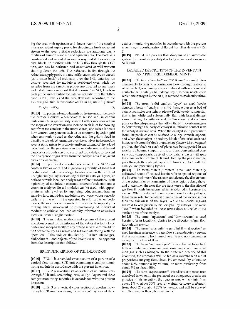
[0002] 1. Field of the Invention [0003] This invention resides in the ?eld of NO,C emissions from combustion facilities, and methods and plant equipment using selective catalytic reduction (SCR) for controlling and reducing the emissions. [0004] 2. Description of the PriorArt [0005] A Widely used process for the reduction of NO,C emissions from coal-?red utility boilers and in combustion ?ue gases in general is the process knoWn as selective cata lytic NO,C reduction (SCR). In this process, the NO,C in the ?ue gas is reacted With oxygen and ammonia over a solid catalyst Which is either a metal such as titanium, vanadium or plati num, or a Zeolite or a ceramic, to reduce the nitrogen in NO,C to molecular nitrogen With Water as a by-product. The utility industry has invested billions of dollars in SCR units, and these units collectively utiliZe a volume of catalyst that is on the order of 200,000 m2. [0006] The performance of an SCR unit, as measured by the change in NO,C concentration across the unit (ANOX), depends on the catalyst activity and the area velocity Av of the unit according to the relation
ANofi-amv (1)
[0007] Where K is the catalyst activity andAV is de?ned by the relation
Q (2) A, = TS
[0008] Where Q is the ?ue gas ?oW rate through the unit, V is the bulk catalyst volume, and AS is the surface area of the catalyst per unit volume of the catalyst. Contributing to the catalyst activity K are such factors as the mass transfer coef ?cient, the kinetic rate constant and various geometric fac tors. The typical SCR catalyst is rated by its vendor With an initial catalyst activity K0. The catalyst activity and hence the NO,C reduction potential of the unit decrease gradually over time as the catalyst is subjected to macro- and micropore diffusion, absorption, desorption, chemical reactions involv ing the catalyst itself, and catalyst poisons. To maintain the desired level of NO,C reduction, the rate of ammonia injection must then be increased to compensate for the decrease in catalyst activity. This in turn results in greater amounts of unreacted ammonia leaving the unit (the “ammonia slip”) and therefore greater cost in operating the unit, a greater risk of pollution, and possible adverse impacts on doWnstream equipment. Catalyst degradation is further complicated by the fact that in large catalytic reactors the catalyst is deployed in
Dec. 10, 2009
tWo or more distinct and separated layers, With different lay ers tending to degrade at different rates. Even in a single layer, the catalyst can undergo different degradation rates at differ ent locations in the layer. As the catalyst continues to degrade, replacement or regeneration is eventually necessary. Typi cally, one-third to one-fourth of the catalyst is replaced or regenerated approximately every 15,000 to 25,000 hours of continuous use.
[0009] A Well-run boiler or combustion facility Will have a catalyst management procedure for the SCR unit that Will alloW the facility to comply With the regulatory requirements for NO,C and NH3 emissions, and yet conform to the outage schedule for the facility. Periodic monitoring of the catalyst provides the most ef?cient use of the catalyst and alloWs operators to maintain the facility in compliance With the regulations. Monitoring methods that are in current use intro duce ine?iciencies of their oWn, hoWever. [0010] One of these methods is by monitoring the ammonia slip. Another is by monitoring the ammonia content of the ?y ash. Either method provides only an indirect indication of the catalyst activity, and only a gross or overall indication of any loss in activity. These methods Will not differentiate betWeen situations in Which all catalyst layers are losing activity at approximately the same rate from those in Which upstream layers are losing activity at a greater rate than those doWn stream. A further dif?culty is that increases in the ammonia slip or in the ammonia content of the ?y ash may be the result of factors other than catalyst activity, such as an ammonia injection grid that is not properly adjusted or any other irregu larity in the ammonia injection system. [0011] Another monitoring method is that in Which samples of catalyst are removed from the reactor and trans ferred to a laboratory for direct determinations of the catalyst activity or the activity ratio K/KO. This can also be done With catalyst coupons retained in the reactor in a special removable holder. Removal of the samples or coupons hoWever usually requires that the unit be taken off-line. Unless the unit is expressly shut doWn for the sampling, the time interval betWeen sampling opportunities Will be dictated by the out age schedule of the unit rather than concerns over the catalyst activity and can be very long. For those units operating on a schedule that is designed to accommodate the oZone season, for example, outages may occur as seldom as once or tWice a year. For units operating year-round, the sampling frequency may be even loWer, such as once every other year. A further problem With the WithdraWal of catalyst samples is that the analyses of these samples provide no information regarding hoW any observed decrease in catalyst activity occurred, i.e., Whether the decrease occurred sloWly and gradually over time or by a step change resulting from a boiler upset, a fuel change, or some other occurrence not related to the SCR unit itself.
SUMMARY OF THE INVENTION
[0012] The present invention resides in modules for moni toring catalytic activity on a localiZed basis in an SCR unit, methods of on-line monitoring of SCR catalyst activity uti liZing such modules, and SCR units that contain such mod ules, all either reducing or eliminating the de?ciencies of the prior art methods. Each module is siZed to extend over a lateral area of a catalyst layer that is small relative to the full area of the layer as Well as the cross section of the gas ?oW stream through the SCR reactor and includes a pair of sam pling probes for draWing samples from the gas stream travers
US 2009/0305425 A1
ing the area both upstream and downstream of the catalyst plus a reductant supply probe for directing a fresh reductant stream to the area. Suitable reductants are ammonia gas, a mixture of ammonia and air, and aqueous urea. The module is constructed and mounted in such a Way that it does not dis rupt, block, or interfere With the bulk ?oW through the SCR unit, and can be activated and deactivated at Will Without shutting doWn the unit. The reductant is fed through the reductant supply probe at a rate suf?cient to achieve an excess (on a mole basis) of reductant over the NO,C entering the catalyst area that the module is positioned over, While the samples from the sampling probes are directed to analyZers and a data processing unit that determine the NO,C levels in each probe and calculate the catalyst activity from the differ ence in NO,C levels and the area How rate according to the folloWing relation, Which is derived from Equation (1) above:
K:Avln(1—ANOX) (3)
[0013] In preferred embodiments of the invention, the mod ule further includes a temperature sensor and, in certain embodiments, a gas velocity sensor. Further modules Within the scope of the invention also include an air inlet for bloWing soot from the catalyst in the module area, and miscellaneous ?oW control components such as an ammonia injection grid When ammonia is used as the reductant, the grid is siZed to distribute the added ammonia over the catalyst in the module area, a static mixer to promote uniform mixing of the added reductant into the gas stream in the module area, and lateral barriers or shrouds siZed to surround the catalyst to prevent the divergence of gas ?oWs from the catalyst area to adjacent areas or vice versa.
[0014] In preferred embodiments as Well, the SCR unit contains tWo or more, and in general a plurality, of these test modules distributed at strategic locations across the Width of a single catalyst layer or among different catalyst layers, or both, to provide localiZed analyses at different locations. With a plurality of modules, a common source of reductant and a common analyZer for all modules can be used, With appro priate sWitching valves for supplying reductant and draWing samples from individual modules in sequence, either periodi cally or at the Will of the operator. In still further embodi ments, the modules are mounted on a movable support per mitting lateral movement or re-positioning of individual modules to achieve localiZed activity information at various locations from a single module.
[0015] The modules, methods and systems of the present invention permit the monitoring of the catalyst activity to be performed independently of any outage schedule for the SCR unit or the facility as a Whole and Without interfering With the operation of the unit or the facility. Further advantages, embodiments, and objects of the invention Will be apparent from the description that folloWs.
BRIEF DESCRIPTION OF THE DRAWINGS
[0016] FIG. 1 is a vertical cross section of a portion of a vertical ?oW-through SCR unit containing a catalyst moni toring module in accordance With the present invention. [0017] FIG. 2 is a vertical cross section of an entire ?oW through SCR unit containing three catalyst layers and three catalyst monitoring modules in accordance With the present invention.
[0018] FIG. 3 is a vertical cross section of another How through SCR unit containing three catalyst layers and three
Dec. 10, 2009
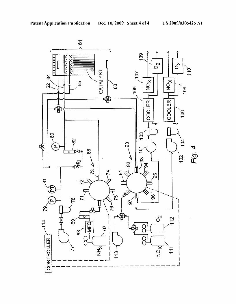
catalyst monitoring modules in accordance With the present invention, in a con?guration different from that shoWn in FIG. 2. [0019] FIG. 4 is a process How diagram of an automated system for monitoring catalyst activity at six locations in an SCR unit.
DETAILED DESCRIPTION OF THE INVENTION AND PREFERRED EMBODIMENTS
[0020] The terms “reactor” and “SCR unit” are used inter changeably to refer to a continuous ?oW-through reactor in Which an NOx-containing gas is combined With ammonia and contacted With catalyst to undergo any of various reactions in Which the nitrogen in the NO,C is reduced to molecular nitro gen. [0021] The term “solid catalyst layer” as used herein denotes a body of catalyst in solid form, either as a bed of catalyst particles or a unitary piece of solid catalytic material, that is immobile and substantially ?at, With lateral dimen sions that signi?cantly exceed its thickness, and contains pores or though-passages that alloW the NOx-containing gas to How through the body of catalyst in intimate contact With the catalyst surface area. When the catalyst is in particulate form, the particles can be retained on a tray or mesh support, and When the catalyst is a unitary block of material such as a honeycomb ceramic block or a stack of plates With corrugated pro?les, the block or stack of plates can be supported in the reactor by beams, support grids, or other conventional con struction components. Typically, the catalyst layer Will span the cross section of the SCR unit, forcing the gas stream to pass through the catalyst layer in intimate contact With the catalyst and preventing bypass. [0022] The terms “lateral,” “lateral area,” and “laterally delineated section” as used herein refer to spatial regions of the internal volume of the reactor, and denote the dimensions or the extremities or boundaries of these regions along the x and y-axes, i.e., the axes that are transverse to the direction of gas ?oW through the reactor (Which is referred to herein as the Z-axis). Whenused in reference to a section of a catalyst layer, these terms refer to the lateral dimensions of the section rather than the thickness of the layer. While the spatial regions referred to Will generally be occupied by catalyst, the Word “area” When included in these terms does not refer to the surface area of the catalyst. [0023] The terms “upstream” and “downstream” as used herein refer to locations relative to the direction of gas ?oW through the reactor. [0024] The term “substantially parallel ?oW direction” as used herein in reference to a gas ?oW stream denotes a stream that is substantially both non-diverging and non-converging along its direction of How. [0025] The term “ammonia gas” is used herein to include both undiluted ammonia and ammonia mixed With air or an inert gas such as nitrogen. In the preferred practice of this invention, the ammonia Will be fed as a mixture With air, at proportions ranging from about 1% ammonia by volume to about 80% ammonia by volume, or more preferably from about 5% to about 60%. [0026] The term “aqueous urea” is used herein to mean urea dissolved in Water. In the preferred use of aqueous urea in the practice of this invention, the aqueous urea Will contain from about 1% to about 50% urea by Weight, or more preferably from about 2% to about 25% by Weight, and Will be sprayed into the ?ue gas through an atomiZer.

US 2009/0305425 A1
[0027] The term “selectively strike” as used herein in ref erence to an air or gas stream directed to a section of the
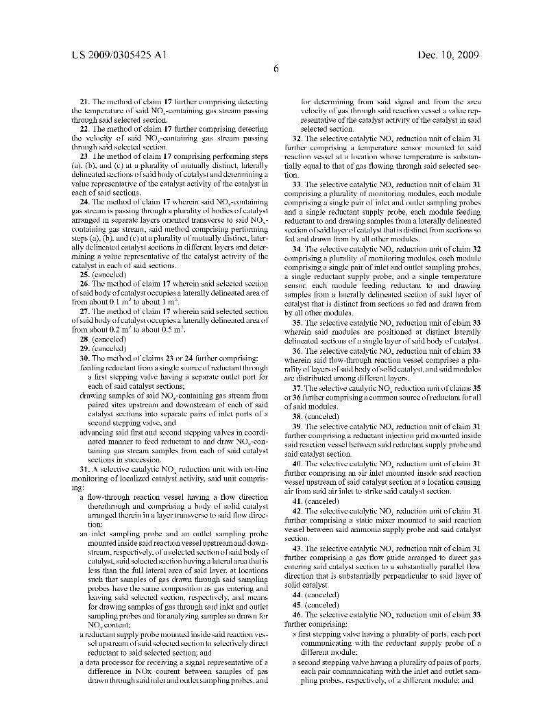
catalyst bed denotes that the entire stream is con?ned to the area With the lateral extremities of the section and does not diverge outside those extremities. [0028] The terms “a” and “an” as used herein mean “one or more,” and are therefore broader in scope than the term “plu rality.” [0029] While this invention is capable of implementation in a Wide range of constructions, applications, and embodi ments, a thorough understanding Will be gained by a detailed examination of a speci?c embodiment. Such an embodiment is shoWn in the draWings and explained beloW. [0030] FIG. 1 represents a partial cross section of an SCR unit taken along the direction of gas ?oW through the unit (the Z-axis), shoWing one test module in accordance With the invention. In this cross section, tWo catalyst layers are shoWn, the ?rst 11 positioned upstream of the second 12 and both spanning the entire cross section of the unit. The How direc tion of NOx-containing gas through this unit is from the top doWn in the vieW shoWn in the Figure. The gas thus passes through the catalyst in the ?rst layer 11 before proceeding to the catalyst in the second layer 12. A single module 13 is positioned to monitor the catalyst activity in a laterally des ignated section 14 of the second catalyst layer 12. The section 14 has lateral extremities, of Which only tWo opposing sides 15, 16 are visible in this cross section, that de?ne an area that is a relatively small portion of the entire cross section of the unit. In preferred applications, the lateral area of the section ranges from about 0.1 m2 to about 1 m2, and more preferably from about 0.2 m2 to about 0.5 m2. The ratio of this area to the cross section area of the entire reactor is preferably about 0.25 or less, and more preferably about 0.1 or less. The shape of the module section area 14 can be square, circular, or any prac tical or convenient shape, and Will be determined by the How con?gurations emerging from the ammonia inlet probe and any lateral barriers (discussed beloW) that are included in the module. The dimensions, area ratio, and shape are not critical to the invention and can vary Widely.
[0031] The ammonia supply probe 17 is a component of the module, and in the embodiment shoWn in the Figure the probe incorporates an ammonia injection grid and is positioned directly upstream of (above) the designated area 14 of the catalyst bed in Which the activity determination is to be per formed. The probe and grid are selected and arranged to produce an ammonia stream that selectively strikes the des ignated area 14 and preferably strikes substantially the entire area. The height of the probe and grid above the catalyst bed Will vary depending on the grid con?guration and any other components included in the module. In most cases, a height of from about 1 foot to about 8 feet (0.3 to 2.4 meters), and preferably from about 2 feet to about 6 feet (0.6 to l .8 meters), Will provide the best results, depending on any additional components that might be placed betWeen the grid and the catalyst surface. [0032] The inlet sampling probe 21 is likeWise positioned upstream of the designated area 14 of the catalyst bed, and the outlet sampling probe 22 is positioned doWnstream of the designated area. In this embodiment, the inlet sampling probe 21 is positioned upstream of the ammonia injection grid 17 to assure that the analysis of the sample draWn through this probe is representative of the gas stream ?oWing through the unit at that level. Both sampling probes preferably include a
Dec. 10, 2009
?lter incorporated into the probe to prevent soot or solid matter in general from entering the lines leading to the ana lyZer(s). [0033] The mounting structures 23, 24 for the ammonia supply probe and grid 17 and for the inlet and outlet sampling probes 21, 22 and all other components of the module are any conventional supports, beams, frames, brackets, or the like that Will secure the components in place Without disrupting or interfering With the gas ?oW through the SCR unit as a Whole. The mounting structures may range from simple angle irons to Which the components are bolted or Welded in ?xed posi tions, to rails along Which the components are slid so that they can be positioned at different locations along a particular catalyst layer. The mounting structures can be combined to make the module a unitary piece of equipment With all com ponents attached, or they can be individual beams or rails for individual components of the module. Accordingly, the mod ule can be manufactured as a separate piece of equipment or constructed as part of the SCR unit itself from individual components. [0034] Further components for optional, and in certain cases preferred, inclusion in a module of the present inven tion, as mentioned above, are a temperature sensor, a soot bloWer, a How recti?er to guide the NOx-containing gas enter ing the module into a substantially parallel ?oW direction, a static mixer doWnstream of the ammonia probe and ammonia injection grid to promote the uniform mixing of the ammonia With the gas flow stream, and a shroud or lateral enclosure Wall as further assurance against lateral diffusion of gases or interfering materials betWeen the catalyst area addressed by the module and adjacent catalyst areas. These optional com ponents can be included individually or in any combination, and all can be mounted to module by conventional mounting ?xtures.
[0035] In the embodiment shoWn in FIG. 1, the module includes a thermocouple 25 centered in the module and posi tioned above, i.e., upstream of, the catalyst area addressed the module. Optionally the thermocouple can be positioned on the doWnstream side of the catalyst area. Temperature sensors other than thermocouples can be used as Well. Examples are thermistors, metallic resistive temperature devices (RTDs), infrared sensors, bimetallic devices, ?uid-expansion devices, and change-of-state temperature sensors. [0036] The module ofFIG. 1 also includes a soot bloWer 26 Which is an air injection inlet Whose purpose is to clear the catalyst area 14 of ash particles that might obstruct the How of gas through the catalyst area. Air is the most convenient, but the bloWer can utiliZe any gas that Will not affect the catalyst.
[0037] A still further component shoWn in the module of FIG. 1 is a How recti?er 27. The recti?er can be any arrange ment of plates, tubes, or grid that guide the bulk gas ?oW toWard the module in a parallel direction. The How recti?er can be similar in design and construction to the How recti?ers that are often used in SCR units as a Whole but reduced in scale to the dimensions of the module. A further component shoWn in the Figure is a static mixer 28. Blade-type static mixers and helical static mixers are examples of mixers that are Widely available from commercial suppliers to the chemi cal engineering industry. Other designs can be used as Well. Here again, the appropriate static mixer Will be one Whose siZe matches the scale of the module. Also shoWn in the Figure is a How measuring device 29 to measure the ?ue gas

US 2009/0305425 A1
velocity approaching the catalyst. Conventional ?oW measur ing devices can be used; examples are thermal anemometers and pitot tubes. [0038] Also included as part of the module of FIG. 1 is the shroud referred to above, in the form of sheet metal Walls of Which only tWo 31, 32 are visible. These Walls enclose the perimeter of the space above the catalyst area 14. A still further component is a portable NO,C analyZer 33 that is shoWn mounted to the ?oWlines extending from the inlet and outlet sampling probes. Portable NO,C analyZers are knoWn in the industry and readily available from commercial suppliers. An example is the non-sampling type MEXA-720NOx AnalyZer of Horiba Instruments Incorporated (Irvine, Calif., USA). Other NO,C analyZers, portable and on-portable, can also be used and are discussed beloW.
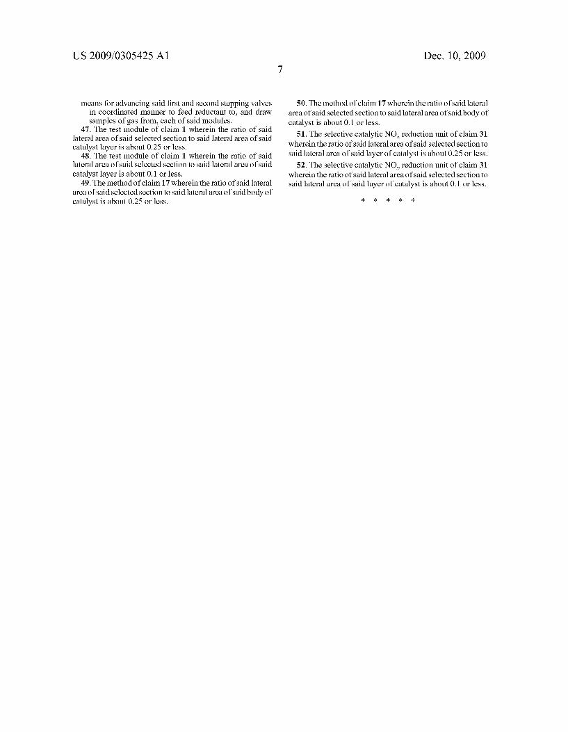
[0039] The number of modules used in a single SCR unit is not critical to the invention and can vary. Preferably, a plural ity of modules are used so that localiZed catalyst activity can be monitored at different sites along the How path of the gas being treated in the unit. Movable modules, as described above, can also serve to provide localiZed monitoring data over Wide areas. Typical con?gurations of the catalyst layers in an SCR unit are shoWn in FIGS. 2 and 3, With different arrangements of modules. In FIG. 2, the SCR unit 41 has three layers 42, 43, 44 of catalyst, and three modules 45, 46, 47 distributed across a single layer. In FIG. 3, the SCR unit 51 likeWise has three catalyst layers 52, 53, 54, and three mod ules 55, 56, 57 are shoWn, one in each layer. The modules in FIG. 3 are movable as indicated by the arroWs, so that each can be placed at any location across the Width of the catalyst bed that it is adjacent to.
[0040] The peripheral equipment and components used in association With the modules of the present invention are conventional components that are knoWn in the boiler and poWer plant industry and readily available from commercial suppliers. The primary peripheral comments include pumps for draWing samples through the sample probes, ?oW control lers for the supply lines for ammonia and air, NO,C analyZers, and, if desired, oxygen analyZers. For NO,C analyses other than by the use of the portable analyZers mentioned above, chemiluminescence NO,C analyZers are of particular interest. Examples are Brand-Gaus Chemiluminescence NO,C AnalyZ ers (Brand-Gaus, LLC, P?ugerville, Tex., USA), ECO PHYSICS Chemiluminescence NO,C AnalyZers (ECO PHYS ICS, INC., AnnArbor, Mich., USA), and Environmental Ana lytical Systems’ Model 400 CLD and Model 400 HCLD Chemiluminescent NO/NO,C AnalyZers (Environmental Ana lytical Systems, Barry’s Bay, Ontario, Canada).AnalyZers for molecular oxygen are also included in certain embodiments of the invention for the purpose of detecting leaks in the sampling system. Examples of oxygen analyZers are the Series 800 Zirconia Oxygen AnalyZer of Illinois Instruments, Inc. (Johnsburg, Ill., USA), the Integrated Type In Situ Zir conia Oxygen AnalyZer Model ZR202G of YokogaWa Cor poration of America (NeWnan, Ga., USA), and the CGA351 Zirconia Oxygen AnalyZer of GE Panametrics (Gymea, NeW South Wales, Australia). [0041] Monitoring systems in accordance With this inven tion can be designed for manual operation or automated operation. Manually operated systems Will be those With manually controlled sample pumps, manually controlled ana lyZers, and manual controls in general for energiZing indi
Dec. 10, 2009
vidual modules or positioning movable modules. An example of an automated system for six test modules in a single SCR unit is shoWn in FIG. 4.
[0042] The system of FIG. 4 performs analyZes from each of the six modules in succession, one at a time. Only one module 61 of the six is shoWn. The How lines to and from the module are an inlet sampling line 62 and an outlet sampling line 63 from the inlet and outlet sampling probes, respec tively, an ammonia supply line 64, and an air supply line 65 for the soot bloWer. TWo stepping valves control the selection of the module that is in use and the progression of the analysis from one module to the next. The ?rst stepping valve 66 is supplied by a single source of anhydrous ammonia gas 67, Whose ?oW rate is controlled by a mass ?oW controller 68, and measured by a How meter 69. The stepping valve rotates betWeen six outlet ports 71, 72, 73, 74, 75, 76, one for each of the six modules. Before reaching a module, the ammonia is combined With air from an air source such as a bloWer 77, Which passes through a ?lter 78, pressure gauges 79, 80, a pressure transmitter 81, and a How meter 82. The same air source feeds air to the air supply line 65 supplying the soot bloWer. The second stepping valve 90 receives gas stream samples from the inlet and outlet sampling lines 62, 63, respectively, through a pair of inlet ports that represent one of six pairs ofinlet ports 91, 92, 93, 94, 95, 96, one for each ofthe six modules. A single pair of outlet ports 97 from the stepping valve leads to a single pair of sample pumps 101, 102, one pump for the inlet samples and the other for the outlet samples. The samples thus draWn pass through ?lters 103, 104 and moisture removers 105, 106 (such as for example thermoelectric coolers), and each sample stream is then passed through a NO,C analyZer 107, 108 and an oxygen ana lyZer 109, 110. The outlets of the analyZers are open to vent. Supplies of NO,C 111 and molecular oxygen 112 are con nected to the system for use in calibrating the analyZers, and a separate source of air 113 is available for cleaning the transfer lines betWeen analyses. The stepping valves 66, 90, and all other components of the system that are susceptible of control in the automated operation of the system are con nected to a common controller 114 such as a computer, a
programmable logic controller, or a segment of the main control system of the utility as a Whole.
[0043] The monitoring of localiZed catalyst activity With the use of the modules described above can be performed While the SCR unit is in full operation, and is preferably performed While the unit is operating at full load. The typical SCR unit has either tWo, three, or four catalyst bed layers, each layer being approximately 40 to 60 square feet (3 .7 to 5 .5 square meters) in lateral area and approximately 3 feet (1 meter) in depth. A typical gas velocity through an SCR unit is approximately 15 feet per second (4.6 meters per second) at an operating temperature of approximately 700° F. (3700 C.). A presently preferred module area is a section that is square in shape With each side measuring 2 feet (0.61 meter) in length. The amount of ammonia fed to the module to pass through the catalyst area covered by the module Will be any amount that achieves a molar excess relative to the NO,C entering the cata lyst at that area. The amount of NO,C entering the area is readily determined by analysis of a sample draWn the inlet sampling probe, thereby alloWing a determination of the appropriate amount of ammonia feed. As noted above, molar ratios in excess of 1.0 are preferred, and molar ratios of about 1.2 or greater are more preferred. In a presently preferred method, a mixture of ammonia and air at an airzammonia