In-house project
32
All right reserved @International Research Institute for Nuclear Decommissioning (IRID) ©International Research Institute for Nuclear Decommissioning In-house project Development of technology for detailed investigation inside the primary containment vessel (on-site demonstration for detailed investigation inside PCV through X-6 penetration) Final report for FY2020 May, 2021 International Research Institute for Nuclear Decommissioning (IRID)
Transcript of In-house project

All right reserved @International Research Institute for Nuclear Decommissioning (IRID)©International Research Institute for Nuclear Decommissioning
In-house project
Development of technology for detailed
investigation inside the primary containment
vessel (on-site demonstration for detailed
investigation inside PCV through X-6 penetration)
Final report for FY2020
May, 2021
International Research Institute for Nuclear Decommissioning
(IRID)

©International Research Institute for Nuclear Decommissioning
1Contents
1.Background and purpose of the project
2.Overview of the project
3.Project organization
4.Implementation items and results
4.1 Access and investigation equipment
4.2 Equipment related to establishing the access route
4.3 Other ancillary facilities
4.4 Equipment for collecting fuel debris
4.5 Conducting field demonstrations
4.6 Others
5.Summary and future plan

©International Research Institute for Nuclear Decommissioning
21. Background and purpose of the project
【Overview of the PCV cross-section and
the investigation points】
Reactor building
structure
Reactor pressure
vessel (RPV)
Primary
containment vessel
(PCV)
Pedestal
Major investigation area
(inside the pedestal)
X-6 penetration
【Purpose】
The access and investigation equipment is
intended to enter through the X-6 penetration
that was used for a previous investigation inside
the PCV after making a larger-diameter opening.
A detailed investigation will be undertaken to
verify the effectiveness of this technology.
Additionally, fuel debris collection equipment will
be installed to collect the depositions in the PCV,
and the effectiveness of the developed
technology will be confirmed.
【Background】As a result of investigation inside the primary
containment vessel (PCV) of Unit 2 conducted in
January 2018, pebble-and clay-like depositions
were confirmed on the entire pedestal bottom.
Moreover, a part of the fuel assemblies had
dropped on the bottom, and the depositions
identified in the surrounding area were
presumed to be fuel debris. CRD bottom

©International Research Institute for Nuclear Decommissioning
3
FY2017-2018: Development of Technology for Detailed Investigation Inside the PCV
Development of Sampling Technology for
Retrieving Fuel Debris and Reactor Internals.
Development of Technology for Increasing
the Scale of Fuel Debris Retrieval in Stages
Development of Technology for
Retrieving Fuel Debris and Reactor
Internals
FY2016-2017: Development of Technology for Investigation Inside the PCV
FY2018-2019: Development of Technology for Detailed Investigation Inside the PCV (onsite
demonstration for detailed investigation inside the PCV through X-6 penetration)
2. Overview of the project
FY2020-2023: Development of Technology for Detailed Investigation Inside the PCV (onsite
demonstration for detailed investigation inside the PCV through X-6 penetration)
Subsidy
projects
IRID
In-house
project

©International Research Institute for Nuclear Decommissioning
4Project organization
東京電力ホールディングス株式会社
○ 現場実証における工程管理
○ 現場実証フェーズのマネジメント
○ 役所等対外対応
東芝エネルギーシステムズ株式会社
○ X-6ペネ ハッチの開放 全体計画
○ X-6ペネ ハッチ開放に向けた準備
〇現地実証
東京電力ホールディングス株式会社
○ アクセス・調査装置
①現場状況を考慮したモックアップ試験
②作業訓練
○ 少量燃料デブリ回収装置
①作業訓練
○ 現場実証
技術研究組合 国内廃炉研究開発機構(本部)
○ 開発計画の策定と技術統括
○ 技術・装置開発の進捗などの技術工程管理
○ 装置開発フェーズにおけるマネジメント
三菱重工業株式会社
○ アクセス・調査装置
①現場状況を考慮したモックアップ試験
②作業訓練
○ アクセスルート構築のための関連機器
①作業訓練
○ その他付帯設備
①設計、製作
○ 少量燃料デブリ回収装置
①作業訓練
○ 現場実証
→アクセス・調査装置、その他の作業訓練
→現地実証(内部詳細調査)
→X-6ペネ ハッチ関連装置の作業訓練
→現地実証(X-6ペネハッチ開放)
→アクセス・調査装置の作業訓練
→現地実証(アクセス・調査装置運転)
International Research Institute for Nuclear Decommissioning (IRID)
• Development planning and technological
management
• Technological process control: Progress of
technology and equipment development
• Technology management for development phase
Tokyo Electoric Power Company (TEPCO) Holdings, Inc.
• Schedule management for site verification
• Management of the field demonstration phase
• Administration work, including communication
with government
Mitsubishi Heavy Industries, Ltd. Toshiba Energy Systems and
Solutions Corporation
TEPCO Holdings, Inc.
→Access and investigation apparatus and
other operation training
→Conducting field demonstrations (detailed
investigation inside a PCV)
→Operation training for X-6 penetration
hatch opening equipment
→Site verification (X-6 penetration
hatch opening)• Access and investigation apparatus
1.Mock-up test considering the site
condition
2.Operation training
• Equipment related to establishing the
access route
1.Operation training
• Other ancillary facilities
1.Design and manufacturing
• Small-amount fuel debris collection
equipment
1.Operation training
• Conducting field demonstrations
• Overoll plan of X-6 penetration hatch
opening
• Preparation for X-6 penetration hatch
opening
• Conducting field demonstrations
→Operation training for access and
investigation apparatus
→Site verification (access and
investigation apparatus operation)
• Access and investigation apparatus
1.Mock-up test considering the site
condition
2.Operation training
• Small-amount fuel debris collection
equipment
• Operation training
• Conducting field demonstrations

©International Research Institute for Nuclear Decommissioning
5
【Mock-up for the arm (test for passing through the X-6 penetration) 】
Simulated X-6
penetration
structure
CRD rail
Arm (link)Carriage Insert
Camera on the arm head
Travelling test rail
・The test result confirmed that the arm can pass through the X-6 penetration without interference.
・Interference risks can be reduced by appropriate motion control to prevent moving the link part backward
under its own weight and moving forward by a driving motor of the link part. Consequently, swinging motions
of the arm head in a horizontal direction were controlled (both amplitudes are approximately 20mm).
・The minimum clearance in the test is 10mm. The clearance will be increased by adjusting the height of the
insert position.
Wand
Test condition (overview) Test condition (exit of X-6 penetration)
Simulated X-6 penetration structure
模式図
アーム傾き X-6ペネ
キャリッジ
走行レール
Minimum clearance
アームを傾けた際に
アームが後退する動き
アームが前進する動き
水平方向の揺動
両者の動きをバランスさせることで揺動を低減
4. Implementation items and results
(1) Mock-up test considering the site condition
4.1 Access and investigation equipment
Swinging motions can be reduced by balanced motion of the two parts.

©International Research Institute for Nuclear Decommissioning
6
There are concerns over interference and other issues because of the narrowness of the spaces in the
enclosure. Therefore, the mechanical interference was checked after the arm and Dexter were installed
in the cell, and electrical connections including the camera connection were also checked.
The test results confirmed that the arm and the maintenance manipulator can be moved without
mechanical interference, and electric functions (control and image signals) are at satisfactory levels.
【Installation test】
Maintenance manipulator (Dexter)
Arm
Installing equipment in the enclosure
(1) Mock-up test considering the site condition
4.1 Access and investigation equipment

©International Research Institute for Nuclear Decommissioning
7
【A mock-up test for the maintenance manipulator (Dexter)】
・A mock-up test for Dexter using a simulated arm in the enclosure was carried out.
・Feasibility of remote operation by Dexter was confirmed according to a procedure
manual.
・Arm camera replacement
Removed and installed the arm camera, bracket, and
cable connector using a remote-operated bolt.
Simulated arm
Arm camera
Cable
Remote-operated bolt
Dexter arm
Bracket
Removal of the arm camera Removal of the bracket
Bracket
Remote-
operated bolt
Cable connecter
Bracket
Arm camera
Remote-
operated bolt
(1) Mock-up test considering the site condition
4.1 Access and investigation equipment

©International Research Institute for Nuclear Decommissioning
8
【A mock-up test for the maintenance manipulator
(Dexter)】
Enclosure camera
Dexter
Stand
Stand
Enclosure camera
・Change of the camera position in the enclosure
Removal and installation of a winch hook on the
enclosure camera, withdrawal of the camera from
the stand installed in the enclosure, and insertion
of the camera into another stand.
Stand
Enclosure camera
Withdrawal of the enclosure camera Insertion of the enclosure camera
Winch hook
Winch hook
(1) Mock-up test considering the site condition
4.1 Access and investigation equipment
©International Research Institute for Nuclear Decommissioning
9
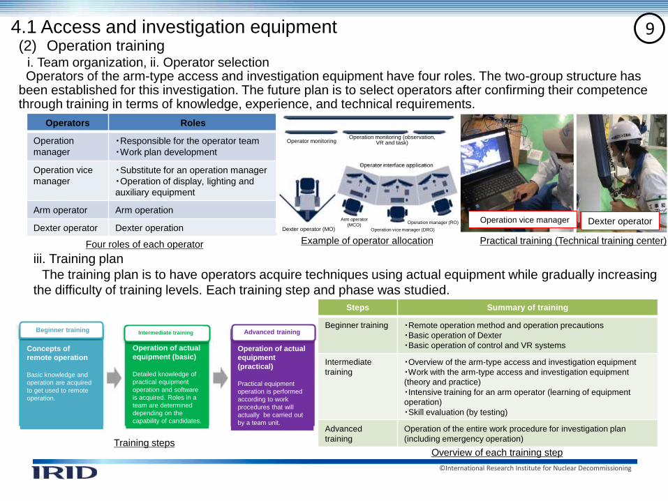
iii. Training plan
The training plan is to have operators acquire techniques using actual equipment while gradually increasing
the difficulty of training levels. Each training step and phase was studied.
(2) Operation trainingi. Team organization, ii. Operator selection Operators of the arm-type access and investigation equipment have four roles. The two-group structure has
been established for this investigation. The future plan is to select operators after confirming their competence through training in terms of knowledge, experience, and technical requirements.
4.1 Access and investigation equipment
Operators Roles
Operation
manager
・Responsible for the operator team
・Work plan development
Operation vice
manager
・Substitute for an operation manager
・Operation of display, lighting and
auxiliary equipment
Arm operator Arm operation
Dexter operator Dexter operation
Example of operator allocation
Training steps
Practical training (Technical training center)
Dexter operatorOperation vice manager
Steps Summary of training
Beginner training ・Remote operation method and operation precautions
・Basic operation of Dexter
・Basic operation of control and VR systems
Intermediate
training
・Overview of the arm-type access and investigation equipment
・Work with the arm-type access and investigation equipment
(theory and practice)
・Intensive training for an arm operator (learning of equipment
operation)
・Skill evaluation (by testing)
Advanced
training
Operation of the entire work procedure for investigation plan
(including emergency operation)
Four roles of each operator
Overview of each training step
Operation of actual
equipment (basic)
Detailed knowledge of
practical equipment
operation and software
is acquired. Roles in a
team are determined
depending on the
capability of candidates.
Operation of actual
equipment
(practical)
Practical equipment
operation is performed
according to work
procedures that will
actually be carried out
by a team unit.
Beginner training
Concepts of
remote operation
Basic knowledge and
operation are acquired
to get used to remote
operation.
Intermediate training Advanced training
Operator monitoring
Operator interface application
Arm operator
(MCO)Operation vice manager (DRO)
Operation manager (RO)
Dexter operator (MO)
Operation monitoring (observation, VR and task)

©International Research Institute for Nuclear Decommissioning
10
Tokyo Electric Power Company (TEPCO) Holdings Inc. investigated depositions accumulated in the X-6
penetration and acquired more detailed information on the distribution of the deposition in the penetration
than existing image information.
The test results will be reflected in the future operational plan, its verification, and training.
The image information of the distribution in the X-6 penetration provided by TEPCO Holdings is as shown
below.
Horizontal section view (directly upward direction)
DepositionPCV sideR/B side
Horizontal section view (diagonally upward direction)
R/B side
PCV side
Deposition
Vertical section view (right side view from R/B)
Vertical section view (left side view from R/B)
R/B sidePCV side
PCV sideR/B side
Deposition
Deposition
4.2 Equipment related to establishing the access route(1) Operation training
【Investigation of depositions accumulated in the X-6 penetration】

©International Research Institute for Nuclear Decommissioning
11
【Overview】
【Progress status in FY 2020】
➢ The X-6 penetration hatch is opened by remote operation to establish the access route through which the investigation
equipment enters the PCV from the X-6 penetration, while ensuring that the isolation room*1) functions as the PCV boundary.
➢ The site test was carried out to confirm operability of equipment. Additionally, detailed work steps based on training results
were created and the site investigation was conducted.
【Hatch isolation room】○ Functions:
➢ Serves as a boundary while the hatch is being
opened.
➢ Serves as a boundary/shielding by means of an air-
tight door after the hatch has been opened.
○ Specifications: Approx. 5.5ton/W1.7×L5.3×H2.5m
【Isolation room in the stage】○Functions:
➢ Serves as a boundary covering the interior of
the concrete stage in the area from the X-6
penetration sleeve to the hatch isolation room.
○ Specifications: Approx.
1ton/W1.2×L1.7×H1.8m
【Common specifications】○Pressure resistance:6kPa(G)(1F=2
management value 5.5kPag or less)
○Main material: Carbon steel
*1) Isolation room: In-stage isolation room, hatch isolation room and robot carry-in room are collectively called “isolation room.”
【Hatch opening device】○Functions:
➢ Opens the hatch of the X-6 penetration
○Specifications: Approx.
2.3ton/W1×L2×H1.6m
【Robot carry-in room】○Functions:
➢ Serves as a boundary while the hatch is being
opened /during carry-in and carry-out of equipment
○ Specifications: Approx. 8ton/W1.7×L5.3×H2.5m
Hatch opening device (installed in the isolation room
Isolation room (full view from behind)
(Specifications and structures of
the isolation room>
Robot carry-in room
4.2 Equipment related to establishing the access route(2) X-6 penetration hatch opening: The overall plan and preparation
X-6
penetration
Concrete
stage
Earthquake resistance support
L Approx.8.2m W Approx.1.7m
H Approx.2.5 m

©International Research Institute for Nuclear Decommissioning
12
Hatch opening by using a hook toolFastened bolt releasing work using a hole saw
➢ The operability test for the main steps was conducted to confirm the work procedure and allocation of the workers and the
work hours.
➢ Work hours in each step to finish work within specified work hours at the site were confirmed.
➢Site investigation of the inside of the reactor building and the west yard was undertaken to verify hatch
opening at the site. The information obtained in this investigation will be utilized for the site verification.
Detecting buried metal in the reactor buildingMeasuring the west yard
【The operability confirmation test】
【Site investigation】
In-stage isolation room installation work
In-stage isolation
room
Hook tool X-6 penetration
hatch
Hatch opening
device (the arm
head)
ペネ前北西エリア付近
4.2 Equipment related to establishing the access route(2) X-6 penetration hatch opening, entire planning and preparation
M16 bolt
Hole saw
Checking dimensions of the
large object carry-in entrance The northwest area in
front of the penetration

©International Research Institute for Nuclear Decommissioning
134.3 Other ancillary facilities ・System image
Access and investigation
equipment main unit, X-6
penetration connecting
structure, etc.
・Actual system plan
Water supply
system
Ventilation
system
Other systems
PCV, X-6 penetration
【Main lines】① Water supply line for abrasive water jet (AWJ) unit
② Nitrogen supply line to check sealing of the X-6
penetration connection structure flange
③ Nitrogen purge line connecting to a maintenance
manipulator in the enclosure
④ Nitrogen supply line for air actuating valve
⑤ Nitrogen (air) exhaust line
⑥ Dehumidifying circulation line of the enclosure
①
②
④
⑤
③
⑥
No.1
No.3
No.2
No.6
No.4
No.7
No Revisions since FY 2020 Reasons for revision
1 The valve of a dehumidifying
circulation line(V-VS-003,010) was
replaced with an opening control
valve.
Improvement of operation
performance by adding a flow
regulation function.
2 A pressure gauge (PT-
001,002,003,004) was displayed in
the operation room.
Improvement of monitoring for the
access and investigation equipment
main unit, the X-6 penetration
connection structure, etc.
3 A pressure gauge (PT-001) function
was added to activate an alarm
when the pressure is high or low.
Improvement of enclosure
protection function.
4 A valve of a water supply line for
AWJ unit (V-WJ-002,004,006,008)
was replaced with an air controlled
valve.
Improvement of operation
performance.
5 A strain measuring instrument of
the X-6 penetration was removed.
Reflecting elimination of
requirements from the connecting
structure side.
6 Nitrogen flow measurement (FT/FI-
020) for arm cleaning was added.
Improvement of management
functions for amount of
consumption of nitrogen.
7 A hose diameter in the exit side of
supply water pump was changed
(25A→20A).
Improvement of procurement
efficiency.
➡The system plan was partly revised and refined to improve the operation performance.
(1) Design and manufacturing
ⅰ. System plan

©International Research Institute for Nuclear Decommissioning
14
・The site investigation was carried out and the site allocation plan was reviewed considering
the latest site environment conditions (radiation dose, distance constraints*, congestions
with other constructions by TEPCO Holdings, Inc., etc.)
* There are constraints on access and distance to the investigation equipment main unit (including sensors), control panels
and abrasive water jet (AWJ) unit from the viewpoint of voltage drop, noise, pressure loss of piping, etc.
Appro
x.1
2m
Approx. 32m
Ap
pro
x.
17
.5m
Control panel (approx.
10 panels) (stored in a
container)
Control panels
(approx.20 panels), WJ
unit (stored in a
container)
Access and investigation
equipment main unit
Inside
R/B
R/B
outside
yard
PCV
Valve rack, etc.
Access and length of piping/cable
to reach the investigation
equipment: Approx. 300mAccess and
length of
piping/cable
to reach the
investigation
equipment:
Approx. 60m
R/B: Reactor building
プラントルーム①
プラントルーム③
プラントルーム⑥
約6m
4.3 Other ancillary facilities
(1) Design and manufacturing ⅱ.Site allocation plan

©International Research Institute for Nuclear Decommissioning
15
Dimensions: Length 542mm x Width 211mm x Height 204mm (including a gripper)Mass: 7.6kg
Parts Revised design
Brush
methodBrush adopter
Improvement of handling capability by a manipulator
Simplified operation of implementation/removal of brush
adopter
Three-divided-brush structure (simplified collecting work)
Common
parts
Camera and light Adopted LED module (temperature reduction in
equipment)
Drawing position
for cables
Improvement of handling capability to avoid interferences
when connecting cables, etc.
0.00
0.20
0.40
0.60
0.80
1.00
1.20
1.40
1.60
0.35 1.0 2.0
鉛球回収量
(g)
鉛球径(mm)
ブラシA
ブラシB
ブラシC
従来品
Divided brush performance test for collecting simulated fuel debris
Mobile drip-proof cover
Drip-proof coverMain
body
Camera
Tool changer
Ac
tua
tor
Brush adapter
Cap
Mirror
LED
Electro-magnetic
valve
Improved brush adapter structure (one-touch method)
➢ Three-divided brush
➢ Quick coupler connection➢ Improved grip (processed ditch
+ stripes)
Some revisions were made to improve handling property by using a manipulator and to reduce
temperature inside equipment.
4.4 Equipment for collecting fuel debris【Brushing method】
Le
ad
co
llectio
n a
mo
un
t (g)
Lead spherical diameter (mm)
Brush A
Brush B
Brush C
Conventional brush
Existing brush
Adopter
Divided brush
Adopter A
Divided brush
Adopter B
Divided brush
Adopter C

©International Research Institute for Nuclear Decommissioning
16
Parts Revised design
Vacuum
vessel
Holder A/D
Spring guide Improvement of handling capability by a manipulator
Common
parts
Camera/light Adopted LED module (temperature reduction in
equipment)
Drawing position for
cables
Improvement of handling capability to avoid
interferences when connecting cables, etc.
Flow of improved holder removal
Holder A
➢ Improved grip (processed ditch + stripes)
Holder D
➢ Improved grip
(processed
ditch)
Spring guide
➢ Unified spring and guide
➢ Improved grip (processed
ditch)
Improved holder structure
Mobile drip-proof cover
Drip-proof coverMain
body
Camera
Tool changer
Ac
tua
tor
Holder A
Holder DMirror
LED
Electro-magnetic
valve
Dimensions: Length 550mm x Width 211mm x Height 204mm (including a gripper)Mass: 8.2 kg
Some revisions were made to improve handling property by using a manipulator and to reduce
temperature inside equipment.
4.4 Equipment for collecting fuel debris【Sucking method】
Holder A
Holder A
removal
Holder DSpring guide
Spring guide
removalHolder D
removal

©International Research Institute for Nuclear Decommissioning
17
【Purpose】 Study of adoption of low heat light because of a concern that internal temperature may exceed the operating
temperature limits.
【Conditions】 Environmental temperature in the PCV: 40℃ Temperature limits: Electro-magnetic valve (50℃), camera
(55℃), actuator (60℃)
【Results】 LED module: BFL359MX24 will be adopted.
BFL366DW12 BFL359MX24 OZLM1D65
Result of temperature test in equipment
Results of radiation-resistance test Results of test for adjusting camera lenses
Low voltage LED module
Number of tests
Type:BFL359MX24
Illu
min
atio
n
ライト候補 装置内温度 耐放性 注1) カメラ画像 電圧降下(計算値) 評価
現行ライト(10W)
× ー ー ー ×
LEDモジュールBFL366DW12×2(1.0W×2)
〇
装置内機器使用温度未満
〇(途中)
照射前後の照度変化微小(変化率-1.5
~1.4%)
〇画像鮮明カメラ絞り:F5.6
5.6V
(140m、0.16A、0.14sq)
〇
LEDモジュールBFL359MX24×1(1.6W)
〇
装置内機器使用温度未満
〇(途中)
照射前後の照度変化微小(変化率-2.9
~-1.5%)
〇画像鮮明:カメラ絞り:F4
2.3V
(140m、0.066A、0.14sq)電圧降下が小さい
◎
LEDモジュールOZLM1D65×2(1.4W×2)
〇
装置内機器使用温度未満
〇(途中)
照射前後の照度変化微小(変化率-2.5
~2.3%)
△他と比較して暗いカメラ絞り:F4
8.3V
(140m、0.24A、0.14sq)
△
注1)LEDモジュール電源OFF、γ線照射(線量率:100Gy/h以上、累積線量:80Gy)今後、LEDモジュール電源ON、γ線照射(線量率:10Gy/h以上、累積線量:20Gy)での照射試験実施予定
Performance comparison results of low voltage LED modules
Device Operating
temperature limits
Camera 0℃~55℃
Electro-
magnetic
valve
-10℃~50℃
Cylinder 0℃~60℃
Temperature limits
45℃ 48℃
47℃
50℃
Camera
Electro-magnetic
valveLight Cylinder
LED module light: BFL359MX24×1
*Space temperature in equipment at 40℃
Test conditions
4.4 Equipment for collecting fuel debris【Temperature reduction in equipment】
Candidate light Temperature in
equipment
Radiation resistance
*1)
Camera image Voltage decrease
(calculated value)
Evalu
ation
Current light
(10W)
x -- -- -- X
LED module
BFL366DW12x
2(1.0Wx2)
〇Less than
temperature used
in equipment
〇 (underway)
Small change in
illumination before/after
irradiation(rate of
change:-1.5-1.4%)
〇Clear image
Camera diaphragm:F5.6
5.6V](140m, 0.16A,
0.13sq)
〇
LED module
BFL359MX24x1
(1.6W)
〇Less than
temperature used
in equipment
〇 (underway)
Small change in
illumination before/after
irradiation (rate of
change:-2.9-1.5%)
〇Clear image
Camera diaphragm:F4
2.3V
(140m, 0.066A,
0.14sq)
Small voltage drop
◎
LED module
OZLM1D65x2(1
.4Wx2)
〇Less than
temperature used
in equipment
〇 (underway)
illumination before/after
irradiation (rate of
change:-2.5-2.3%)
△Darker than others
Clear image
Camera diaphragm:F5.6
8.3V
(140m, 0.24A,
0.14sq)
△
*1) LED module power off, gamma ray irradiation (dose rate: More than100Gyh, accumulated dose rate: 80Gy)The LED module will be power-on, gamma ray irradiation test (dose rate: More than 10Gyh, accumulated dose: 20Gy) will be conducted.
Vertically placed frameCover (Installed cover and movable cover
during testing)
Before irradiation
After 400Gy irradiation
BFL359M24x1 Unit: Lens aperture F4
Initial
position
(41mm
below
brush
head)
Halation can be seen. It is slightly dim.Lead outlines are clear.
Lead outlines are unclear. Lead outlines are clear. Lead outlines are clear.
Lenses aperture F

©International Research Institute for Nuclear Decommissioning
18
The site investigation confirmed the feasibility of satisfying various conditions of the space required
for implementation of the existing building and utilities, and traffic lines of construction vehicles
(reflecting the site investigation results in a layout plan, ref. 4.3 (1) ii.).
Plant room area A (ultra-high pressure open/close
area)
Allocation of the plant room is changed to ensure
enough space for connection of construction
vehicles.
Plant room area B (Unit 2 R/B west yard)
Interferences including an existing shielding room are
planned to be removed in advance.
4.5 Conducting field demonstrations (1) Site investigation
②Room x 2In front of yard in Unit 2 R/B
①Shielding room x 1
MHI allocation area and interferences
①Shielding room x 1 move

©International Research Institute for Nuclear Decommissioning
19
When transporting the enclosure, it is necessary to planarize depressed parts of the floor funnel
at two parts of the transportation route (northwest and southwest of the reactor building (R/B))
for the stable transportation in the R/B.
As a result of comparing the planarizing methods, a planarizing method of filling in depressed
parts with grout was adopted (Reason for selection; Durability of grout is high and there is no
radiation exposure during implementing grout).
Floor funnel on the transportation route Planarizing method using grout
Procedure for enclosure
transportationWest side passage
上面図施工イメージ図
北西エリア
南西エリア
西側通路
4.6 Others(1) Countermeasures for reliability improvement of transporting the access and
investigation equipment
i. Funnel planarization
Enclosure
Enclosure transportation
route (black arrow)
GroutFunnel perforated plate
Slope
Funnel perforated plate Grout
SlopeIron plate
Image viewing of
installation
Grout placing areaTop view
Northwest
area
We
st p
assa
ge
Southwest
area
Northwest area
Southwest area
West
passage
X-6 penetration
Transportation gate
for large materials
① Transportation
②Rotation
④Rotation
③Straight-
running
⑤Installation
Enclosure transportation route (black arrow)
Higher gradient in funnel
compared with other parts
(maximum difference:
Approx.80mm)
Steel plate surface
Slope
Perforated plate surface
Steel plate
Steel plate fo curing
perforated plate
Center of perforated
plate

©International Research Institute for Nuclear Decommissioning
20
As a result of a test that was carried out to determine the cause of transport carriage accidents, it was
confirmed that a high temperature environment would increase the possibility of failure due to the
transistor on the drive controller (DC) substrate.
As a countermeasure against high temperatures, a fin fan was installed on the transistor substrate to
confirm the effectiveness of temperature rise suppression, and the fan was also installed for the
transport carriage.
Transistor
Transport carriage
Fig. Temperature changes of the transistor before/after
countermeasure against high temperatures
(2-hour operation, outside temperature:: 35℃ )
60℃
:Before countermeasure against
high temperature
Tra
ns
isto
r te
mp
era
ture
(℃
)
:After countermeasure against high
temperature (fin-fan installation)
【Legends 】
46℃
Drive controller (DC)
4.6 Others(1) Countermeasures for reliability improvement of transporting the access and investigation
equipment
ii. Study on reliability improvement of the transport carriage
Appearance of fin fan installation DC figure of fin fan installation (top view)
DC main body
DC bottom
plate (in red)
Transistor
Fin
Fan
Base
Base
Base
DC bottom plate
*DC box is
partially cut off.
Fan.
Fin
*DC box
is
partially
cut off.
Time (h)

©International Research Institute for Nuclear Decommissioning
21(2) Study on calibration of gamma sensor and assembly of maintenance gamma sensor
ⅰ. Study on calibration of gamma sensor
4.6 Others
Relationship with spatial dose rate and output voltageRelationship with output voltage and temperatures of
detector
Test environment for measuring the
distribution of radiation dose
Overlapping image of measurement result and
panoramic image
Corresponding to
directions of high-dose
rate and radiation
source
Overview of gamma sensor and image figure of estimating gamma radiation source
Nearly linear
shapeNearly linear
shape
Equivalent to 1000Gy/h
considering shielding effects
of collimator and etc.
• To ensure a dynamic range of approximately 1Gy/h – 1000Gy/h (assuming isotropic radiation source), output voltage was calibrated to be an appropriate value for spatial dose rate, and its nearly linear shape was confirmed.* Silicon diode with temperature dependency was used as a detector.
• Irradiation test was carried out after calibration. The test result confirmed that the direction of the gamma sensor to detect radiation dose was appropriate.* A gamma sensor is designed to measure the distribution of gamma source in the PCV, and to contribute to estimating the location and distribution of fuel
debris in combination with measured data of the in-air laser light cutting device.
Rotation axis of
collimator
Rotation axis of sensor
Measured data of in-air laser light
cutting device
Detector
Gamma sensor
Radiation
source
Collimator
Pedestal
SlitImage view of estimated
gamma ray source
Strong
Week

©International Research Institute for Nuclear Decommissioning
22
Appearance of calibration facility
Appearance of basic performance inspection
Maintenance gamma sensor
Relationship between output voltage of detector and spatial dose rate
Maintenance gamma sensor: Test Use FF-A (red)
Gamma sensor: FF-A (blue)
Confirmed as having nearly
the same detection
performance.
• Manufacturing of maintenance gamma sensor, basic performance inspection and calibration were carried out.
* A maintenance gamma sensor is used when maintenance of the gamma sensor is required
(2) Study on calibration of gamma sensor and assembly of maintenance gamma sensor
ⅱ. Assembly of maintenance gamma sensor
4.6 Others
Oven and detector
Radiation Sources Ambient Temperature
Thermocouple (near)

©International Research Institute for Nuclear Decommissioning
23(3) Design, manufacturing and verification of caulking coating tool
Items Test results
① Coating test A coating test of a mock-up (simulated
touch plate) was carried out.
⇒Possible to coat more than the area of
φ600mm by remote operation.
② Pressure
resistance, air-
tightness and
leakage tests in
the coating area
Caulking coating parts of a mock-up was
pressurized up to 11kPaG (maximum
value of differential pressure in the PCV
and the enclosure) to confirm pressure
resistance and air-tightness, and measure
leakage amount
⇒No deformation was confirmed by visual
observation.
⇒Leakage rate was confirmed to be less
than 0.05vol%/h.
➢ Design and manufacturing of *caulking coating
tool Items Specifications
External
dimensions
H266mm×W293mm×L493mm
Weight 12.9kg
Driving method Nitrogen gas supply (0.5MPa)
Coating method Spray
Caulking
materials
Styrene-butandiene rubber (SBR)
Xylene (solvent)
Coating
performance
Coating area: φ600mm
Pressure resistance in coating area:
11kPa
*A tool designed to spray caulking materials to seal an isolation valve
when a sheet leak occurs at the isolation valve sealing part.
Spray nozzle (four nozzles)Caulking tank
(400ml×2)
N2 gas cylinder for spray
Tool changer (connection part of the arm)
Air cylinder for nozzle
positioning
➢ Performance verification by a single function test
Caulking coating toolSimulated touch plate
Mock-up (simulated
touch plate)
Coating
surface
After coating caulking material
Coating test facility
Pressure resistance and leakage test
4.6 Others

©International Research Institute for Nuclear Decommissioning
24
➢ Overview of the DPTE container
Items Specifications
External dimensions φ413mm×L1298mm×t1.5mm
Weight Approx. 95kg
Materials Container/lid: SUS304
Sealing part: Silicon rubber
Drawing part: SUS304 (main structure
part)
Containing part Containing part: Less than
φ300mm×L1100mm
Containing weight: Less than 50kg
Pressure resistance
and leakage
Pressure resistance:-5~10kPaG、Leakage amount: Less than 4×10⁻²Pa・m3/s
Major use Carry-in/out of investigation sensor
and tools
➢ Design of the DPTE container (for carry-in/out of sensors and tools)
✓ It is a cylindrical type container installed on the DPTE port
located at the side of the enclosure to carry in/out
investigation sensors and tools, and to carry out fuel debris.
✓ The DPTE container is designed to fit onto a port via a
double door interface. Materials can be transported while
maintaining airtightness inside the enclosure and
atmosphere in the reactor building to prevent spreading
contamination.
(stroke)
Main body
of container
DPTE350 port Container lid
Gripping tool for
manipulator
Drawing part
Contained
materials
DPTE container
(4) Design, manufacturing and verification of the DPTE container (1/2)
4.6 Others
©International Research Institute for Nuclear Decommissioning
25
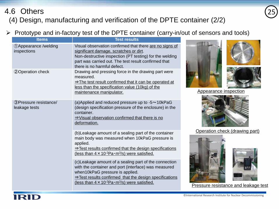
➢ Prototype and in-factory test of the DPTE container (carry-in/out of sensors and tools)Items Test results
①Appearance /welding
inspections
Visual observation confirmed that there are no signs of
significant damage, scratches or dirt.
Non-destructive inspection (PT testing) for the welding
part was carried out. The test result confirmed that
there is no harmful defect.
②Operation check Drawing and pressing force in the drawing part were
measured.
⇒The test result confirmed that it can be operated at
less than the specification value (10kg) of the
maintenance manipulator.
③Pressure resistance/
leakage tests
(a)Applied and reduced pressure up to -5~10kPaG
(design specification pressure of the enclosure) in the
container.
⇒Visual observation confirmed that there is no
deformation.
(b)Leakage amount of a sealing part of the container
main body was measured when 10kPaG pressure is
applied.
⇒Test results confirmed that the design specifications
(less than 4×10⁻²Pa・m3/s) were satisfied.
(c)Leakage amount of a sealing part of the connection
with the container and port (interface) was measured
when10kPaG pressure is applied.
⇒Test results confirmed that the design specifications
(less than 4×10⁻²Pa・m3/s) were satisfied.
Appearance inspection
Operation check (drawing part)
Pressure resistance and leakage test
(4) Design, manufacturing and verification of the DPTE container (2/2)
4.6 Others

©International Research Institute for Nuclear Decommissioning
26(5) Improvement of deposition removal
equipment
➢ Performance validation of cable removal
ItemsMock-up in
FY2020
Mock-up in
FY2019
Mock-up CRD rail
Space between left
and right
One side:
600mm
One side:
200mm
Grating scaffold on the
CRD rail Mock-up No mock-up
Simulated
deposition
(*)
Remaining
cablesNumber
of cables11 cables ←
Length Approx. 8m Approx.13m
DepositionApprox. 15L Approx. 38L
When a performance test was carried out in FY 2019,
a cable was caught in between the partition for testing
and the CRD rail and remained on the CRD rail.
In FY 2020, performance validation of deposition
removal was re-confirmed after reflecting the latest
information of the deposition and reviewing a mock-up
facility.
The test results confirmed that the range of cable
removal was extended (a cable remaining at the upper
half of a route that the arm-type access equipment will
pass through was almost totally removed.
*Latest information
Mock-up (FY2020) Mock-up (FY2019)
Grating scaffold
CRD rail (wide space between left ang right CRD rail (narrow space
between left and right)
Confirmation results (FY2019)
Confirmation results (FY2020)
350m
m
Cable
CRD rail
CRD rail
Partition for testing
Partition for testing
4.6 Others

©International Research Institute for Nuclear Decommissioning
275. Summary and future plan
(1) Summary of achievements in FY 2020
a. Access and investigation equipment:
i) The X-6 penetration pass-through test of the investigation arm test was carried out.
The test results confirmed that the arm can pass through a narrow area and that
controllability was improved.
ii) A mock-up test of a maintenance manipulator was carried out. The test results verified
that the camera for the investigation arm can be replaced and the position of camera in the
enclosure can also be changed by remote operation.
b. Isolation room and hatch opening equipment:
An operability test was carried out for the site operation. Additionally, detailed work steps
were created based on training results and the site investigation was conducted.
c. The design of fuel debris collection equipment was improved and modified, and the site
allocation plan was reviewed based on the site investigation results.
(2) Plans for FY 2021
a. Testing of the access and investigation equipment will be continued in factories (UK/Japan),
after which mock-up tests will start.
b. A field demonstration for other related equipment for establishment of the access route will
start accordingly after training.

©International Research Institute for Nuclear Decommissioning
28
Appendix

©International Research Institute for Nuclear Decommissioning
29Developed technology
X-6 penetration connecting structure
Arm-type access and
investigation
equipment(arm and enclosure)
Extension pipe X-6 penetration
PCVPedestal
Equipment and
structures
Main purpose
Arm-type access and
investigation
equipment
Acquisition of data on the inside of PCV (equipped with sensors), removal
of obstacles (equipped with tools)
X-6 penetration
connecting structure
Construction of PCV boundary and provision of access for arm (equipped
with isolation valve)
Extension pipe Shielding and provision of access for arm
Isolation room Shielding and construction of PCV boundary while X-6 penetration lid is
open (before X-6 penetration connecting structure is attached)
Deposit removal device Removal of deposit, etc. from inside the X-6 penetration
Isolation room(hatch isolation room)
X-6 penetrationDeposit removal device

©International Research Institute for Nuclear Decommissioning
30
サービスパネル
仕切弁
高線量物品搬出口
物品搬出入口背面パネル
8.8m
2m
2.4m
Access and investigation equipment
【 Specifications and structure of the arm enclosure 】
✓ Thickness of outer panel:
10 mm for top and side panels
25 mm for bottom panel
✓ Weight: approximately 30 tons
✓ Main material: Stainless steel
✓ Designed to withstand pressure: −5 to +10 kPaG
✓ Leakage rate: 0.05 vol%/h
✓ Accessories:
Dual-arm manipulator for maintenance, gate valve, camera,
light, etc.
【 Specifications and structure of arm-type equipment 】✓ Mountable sensor: 10 kg or less
✓ Mounted tools: Cutting and gripping tool
water jet cutting tool
✓ Arm length: Approximately 18 m (except wand)
✓ Pressing force: 400 N
✓ Positioning accuracy: ±100 mm
✓ Accumulated dose: 1 MGy
✓ Accessories: Camera and light
物品搬入出口高線量物品搬出口
保守用マニピュレータ
Carriage
Boom link
Tilt mechanism
Censor
Wand*
Telescopic arm
Biaxial joint
*An alternative tool can be equipped.
Manipulator for maintenance
Entrance/exit port
for materials
Exit port for high-
radiation materials
Service panels
Gate valve
©International Research Institute for Nuclear Decommissioning
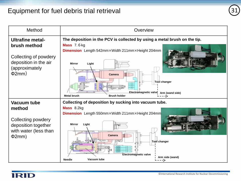
31Equipment for fuel debris trial retrieval
Method Overview
Ultrafine metal-
brush method
Collecting of powdery
deposition in the air
(approximately
Φ2mm)
The deposition in the PCV is collected by using a metal brush on the tip.
Mass 7.6kg
Dimension Length 542mm×Width 211mm×Height 204mm
Vacuum tube
method
Collecting powdery
deposition together
with water (less than
Φ2mm)
Collecting of deposition by sucking into vacuum tube.
Mass 8.2kg
Dimension Length 550mm×Width 211mm×Height 204mm
Camera
Light
Brush holderMetal brush
Mirror
Arm (wand side)
Needle
Mirror
Vacuum tubeArm side (wand)
Camera
Light
Electromagnetic valve
Electromagnetic valve
Tool changer
Tool changer