In-ceiling Housing - CCTV Dubai
20
In-ceiling Housing Installation Manual SHP-3701F
Transcript of In-ceiling Housing - CCTV Dubai

In-ceiling HousingInstallation Manual SHP-3701F

2_ SHP-3701F
TABLE OF CONTENTS
Overview ····························································································································3
What’s Included ·················································································································3
Installation Instructions ······································································································4
Installation (SCP-3430 Series) ···························································································4
Installation (SCP-3370/SNP-5200 SERIES) ······································································9
Installation (SCP-3371/SNP-5300 SERIES) ···································································13
Product Specifi cations····································································································18

SHP-3701F _3
ENG
OVERVIEW
This In-CEILING HOUSING is a mounting ADAPTOR that is designed to mount the smart
dome camera in built-in style on a double-layer ceiling.
WHAT’S INCLUDED
HOUSING SAFETY BRACKET (1EA) SAFETY WIRE (1SET)
TEMPLATE (1EA) SCREW (7EA)
LOWER BRACKET (SCP-3430 Series/SNP-5300 Series)
(1EA)
In-ceiling HousingInstallation Manual SHP-3701F
INSTALLATION MANUAL Fixing Bracket (1EA)

4_ SHP-3701F
INSTALLATION INSTRUCTIONSSelect an installation position or place that can endure more than 4 times of the total
weight of the installation structure.
At least 250mm or more of spare height is required above the CEILING BOARD.
CEILING BOARD’s thickness should be less than 40mm.
Be sure to secure the SAFETY WIRE to avoid a product fall.
If you want to attach the camera to the ADAPTOR, use the only provided SCREWS.
INSTALLATION (SCP-3430 SERIES)
Place the TEMPLATE on the CEILING BOARD and drill a guided hole.
❶ Remove the round fi lling (“C”) from the TEMPLATE.
➋ Place TEMPLATE A onto the CEILING BOARD to which you will attach the ceiling
mount ADAPTOR and drill a hole of Ø219mm in diameter.
See the fi gure below for the hole shape.
1.
2.
3.
4.
5.
1.
Ø219mm
형판
천장 보드
Ø219mm
250mm 이상일 것
천장보드 40mm 이하일 것
More than 250mm
CEILING BOARD Less than 40mm
TEMPLATE
CEILING BOARD

SHP-3701F _5
ENG
See the fi gure below to fi x the lower BRACKET with the provided SCREWs.
Insert the FRAME SET included in the smart dome camera package into the HOUSING
and fi x it using 3 provided SCREWs.
2.
3.
The lower BRACKET is specifi c to “SCP-3430 Series/SNP-5300 Series”.
하우징
하우징
프레임세트
스크류스크류
FRAME SET
SCREWSCREW
HOUSING
HOUSING
6_ SHP-3701F
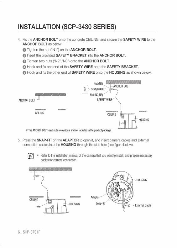
Fix the ANCHOR BOLT onto the concrete CEILING, and secure the SAFETY WIRE to the
ANCHOR BOLT as below:
❶ Tighten the nut (“N1”) on the ANCHOR BOLT.
➋ Insert the provided SAFETY BRACKET into the ANCHOR BOLT.
➌ Tighten two nuts (“N2”,”N3”) onto the ANCHOR BOLT.
➍ Hook and fi x one end of the SAFETY WIRE onto the SAFETY BRACKET.
➎ Hook and fi x the other end of SAFETY WIRE onto the HOUSING as shown below.
Press the SNAP-FIT on the ADAPTOR to open it, and insert camera cables and external
connection cables into the HOUSING through the side hole (see fi gure below).
Refer to the installation manual of the camera that you want to install, and prepare necessary
cables for camera connection.
4.
5.
M
앙카볼트
천장
너트(N1)
안전브라켓앙카볼트
너트(N2,N3)
안전와이어
천장
하우징
INSTALLATION (SCP-3430 SERIES)
The ANCHOR BOLTs and nuts are optional and not included in the product package.
ANCHOR BOLT
Nut (N1)
Safety BRACKET
Nut (N2,N3)SAFETY WIRE
ANCHOR BOLT
HOUSING
CEILINGCEILING
천장
홀 하우징
하우징
어댑터
스냅핏외부케이블
CEILING
HoleHOUSING
Adaptor
Snap-fi t
HOUSING
External Cable

SHP-3701F _7
ENG
Push the HOUSING inside the CEILING through the CEILING hole, and tighten the
SCREWs (x2) clockwise to fi x the HOUSING on the CEILING.
(The BRACKET will be positioned from <A> to <B> as shown.)
Ensure that the HOUSING is fi rmly secured to the CEILING BOARD.
Connect external cables to the CONNECTOR (ALARM-IN, POWER, RS-485 and ALARM
OUT) that is provided with the camera to be installed, and fi t the CONNECTOR into the
ADAPTOR.
Push in the cables inside the FRAME, and close the ADAPTOR.
Make sure that you wrap the BNC JACK with the insulation tube and use the insulation tape to
seal up the end of the insulation tube lest that it should protrude.
For more information about the cable connection, refer to the installation manual of the camera.
6.
M
7.
M
브라켓
브라켓
<A상태> <B상태>
브라켓하우징
브라켓
스크류시계방향으로 회전
BRACKET
SCREWTurn clockwise
HOUSING
BRACKET
BRACKET
BRACKET
<A> <B>
ALARM IN ALARM OUTRS-485
전원절연튜브
BNC잭어댑터 프레임
하우징
천장
Power
AdaptorBNC JACK
Insulation Tube
Frame
HOUSING
CEILING

8_ SHP-3701F
Hook the SAFETY WIRE to the FRAME’s SAFETY HOOK.
Align the camera with the 22-Pin CONNECTOR of the ADAPTOR, and push the HOOK on
either end of the CAMERA in the RACK direction of the FRAME-SET to secure the two.
When the installation is completed, remove both PROTECTIVE TAPE and PRETOECTIVE COVER
from the lens.
Attach the COVER to the HOUSING. Fit the corner groove of the cover into one of 4
grooves on the HOUSING before fi xing it.
8.
M
9.
INSTALLATION (SCP-3430 SERIES)
하우징
프레임
안전걸이
랙
안전와이어
카메라
어댑터
하우징
보호커버보호테이프
천장HOUSING
Frame
Safety Hook
Rack
SAFETY WIRE
Camera
Adaptor
PROTECTIVE TAPE PROTECTIVE COVER
CEILING
HOUSING
홈
하우징
홈커버
홈홈Groove
Groove
Groove
HOUSING
GrooveCover

SHP-3701F _9
ENG
INSTALLATION (SCP-3370/SNP-5200 SERIES)
Place the TEMPLATE on the CEILING BOARD and drill a guided hole.
❶ Remove the round fi lling (“C”) from the TEMPLATE.
➋ Place the TEMPLATE A onto the CEILING BOARD to which you will attach the
CEILING mount ADAPTOR and drill a Ø219mm hole.
See the fi gure below for the hole shape.
See the fi gure below to fi x the INSTALL BASE that is provided as a camera accessory.
1.
2.
Ø219mm
형판
천장 보드
Ø219mm
Check the arrow head
TEMPLATE
CEILING BOARD

10_ SHP-3701F
Fix the ANCHOR BOLT onto the concrete CEILING, and secure the SAFETY WIRE to the
ANCHOR BOLT as below:
❶ Tighten the NUT (“N1”) on the ANCHOR BOLT.
➋ Insert the provided SAFETY BRACKET into the ANCHOR BOLT.
➌ Tighten two NUTs (“N2”,”N3”) onto the ANCHOR BOLT.
➍ Hook and fi x one end of the SAFETY WIRE onto the SAFETY BRACKET.
➎ Hook and fi x the other end of SAFETY WIRE onto the HOUSING as shown below:
Press the SNAP-FIT on the ADAPTOR to open it, and insert camera cables and external
connection cables into the HOUSING through the side hole (see fi gure below).
Refer to the installation manual of the camera that you want to install, and prepare necessary
cables for camera connection.
3.
4.
M
천장
홀 하우징
INSTALLATION (SCP-3370/SNP-5200 SERIES)
앙카볼트
천장
너트(N1)
안전브라켓앙카볼트
너트(N2,N3)
안전와이어
천장
하우징
The ANCHOR BOLTs and nuts are optional and not included in the product package.
ANCHOR BOLT
CEILING
Nut (N1)
Safety BRACKET
Nut (N2,N3)SAFETY WIRE
ANCHOR BOLT
HOUSING
CEILING
CEILING
HOLE HOUSING

SHP-3701F _11
ENG
Push the HOUSING inside the CEILING through the CEILING hole, and tighten the
SCREWs (x2) clockwise to fi x the HOUSING on the CEILING.
(The BRACKET will be positioned from <A> to <B> as shown.)
Ensure that the HOUSING is fi rmly secured to the CEILING BOARD.
Arrange camera cables and close the hinge doorConnect the cables to the terminal block on the hinge door.
For details, refer to “Camera Wiring” of the camera’s
installation manual.
When done, close the hinge door.
DIP Switch SettingOn the bottom of the camera unit, there are
located one DIP switch for communications
and another DIP switch for ID setting. For
more information, refer to the camera’s
installation manual.
5.
M
6.
7. Protocol(SW2) ID(SW1)
브라켓
브라켓
<A상태> <B상태>
브라켓하우징
브라켓
스크류시계방향으로 회전
BRACKET
SCREWTurn clockwise
HOUSING
BRACKET
<B><A>
BRACKET
BRACKET

12_ SHP-3701F
Installing the camera Install the camera in the arrow direction as shown. Connect the SAFETY WIRE before
installing the camera.
The SAFETY WIRE is of the spring type that is locked on the INSTALL BASE. As shown in
the left fi gure, pull up the wire from the INSTALL BASE to hook it to the SAFETY WIRE hook.
When attaching the camera to the mount, check the arrow directions in the fi gure below before proceeding.
Remove the dome cover from the camera, and install the cover onto the HOUSING.
Fit the corner groove of the cover into one of 4 grooves on the HOUSING before fi xing it.
Installing the camera without removing the dome cover will cause an image out of focus.
8.
9.
SAFETY WIRE
Check the arrow head
Arrow Mark
Arrow Mark
홈
하우징
홈커버
홈
홈
When working on the network PTZ camera,
arrange the network cables through the bottom
hole of the HOUSING.
INSTALLATION (SCP-3370/SNP-5200 SERIES)
Cover Groove
Groove
Groove
GrooveHOUSING

SHP-3701F _13
ENG
INSTALLATION (SCP-3371/SNP-5300 SERIES)
Place the TEMPLATE on the CEILING BOARD and drill a guided hole.
❶ Remove the round fi lling (“C”) from the TEMPLATE.
➋ Place TEMPLATE A onto the CEILING BOARD to which you will attach the ceiling
mount ADAPTOR and drill a hole of Ø219mm in diameter.
See the fi gure below for the hole shape.
See the fi gure below to fi x the lower BRACKET with the provided SCREWs.
1.
2.
Ø219mm
형판
천장 보드
Ø219mm
TEMPLATE
CEILING BOARD
The lower BRACKET is specifi c to “SCP-3430 Series/SNP-5300 Series”.

14_ SHP-3701F
Connect the install base included in the PTZ camera to the housing for installation using
the 4 screws that are included as accessories.
Fix the ANCHOR BOLT onto the concrete CEILING, and secure the SAFETY WIRE to the
ANCHOR BOLT as below:
❶ Tighten the NUT (“N1”) on the ANCHOR BOLT.
➋ Insert the provided SAFETY BRACKET into the ANCHOR BOLT.
➌ Tighten two NUTs (“N2”,”N3”) onto the ANCHOR BOLT.
➍ Hook and fi x one end of the SAFETY WIRE onto the SAFETY BRACKET.
➎ Hook and fi x the other end of SAFETY WIRE onto the HOUSING as shown below:
3.
4.
INSTALLATION (SCP-3371/SNP-5300 SERIES)
앙카볼트
천장
너트(N1)
안전브라켓앙카볼트
너트(N2,N3)
안전와이어
천장
하우징
The ANCHOR BOLTs and nuts are optional and not included in the product package.
ANCHOR BOLT
CEILING
Nut (N1)
Safety BRACKET
Nut (N2,N3)SAFETY WIRE
ANCHOR BOLT
HOUSING
CEILING
인스톨베이스 스크류
하단 브라켓 위치표시
Align the position mark on the lower bracket with the screw direction on the install base, and assemble them.
Alignment Guide
Marks of lower
bracket
Install Base Screw

SHP-3701F _15
ENG
Press the SNAP-FIT on the ADAPTOR to open it, and insert camera cables and external
connection cables into the HOUSING through the side hole (see fi gure below).
Refer to the installation manual of the camera that you want to install, and prepare necessary
cables for camera connection.
Push the HOUSING inside the CEILING through the CEILING hole, and tighten the
SCREWs (x2) clockwise to fi x the HOUSING on the CEILING.
(The BRACKET will be positioned from <A> to <B> as shown.)
Ensure that the HOUSING is fi rmly secured to the CEILING BOARD.
5.
M
6.
M
브라켓
브라켓
<A상태> <B상태>브라켓
스크류시계방향으로 회전
브라켓하우징
BRACKET
SCREWTurn clockwise
HOUSING
BRACKET<B><A>
BRACKET
BRACKET
천장
홀 하우징
하우징
어댑터
스냅핏 외부케이블CEILING
HoleHOUSING
Adaptor
Snap-fi t
HOUSING
External Cable

16_ SHP-3701F
INSTALLATION (SCP-3371/SNP-5300 SERIES)
Camera Cable Arrangement and Hinged Door Close Connect the cable to the terminal block on the hinged door. Please
refer to ‘Camera Cabling Diagram’ in the installation manual.
After cabling, please close the hinged door.
7.
Camera Installation Insert the fi xing bracket into the camera bezel. Connect the safety cable fi rst, and then
assemble the camera. The safety cable is wound around the install base like a spring. Pull
from the install base as shown in the fi gure below to mount onto the hook of the safety cable.
After mounting the install base as shown in the fi gure, turn the unit in a clockwise direction.
After turning the unit, connect the screw on the fi xing bracket to the lower bracket.
※ To attach the camera to the mount, refer to the alignment guide marks as shown in the
fi gure.
8.
Alignment Direction Guides
Alignment Direction Guides
Alignment Directions

SHP-3701F _17
ENG
홈
홈커버
홈
홈
Remove the dome cover from the camera, and install the cover onto the HOUSING.
Fit the corner groove of the cover into one of 4 grooves on the HOUSING before fi xing it. Installing the camera without removing the dome cover will cause an image out of focus.
9.
When working on the network PTZ camera,
arrange the network cables through the bottom
hole of the HOUSING.
Cover Groove
Groove
Groove
GrooveHOUSING

18_ SHP-3701F
PRODUCT SPECIFICATIONSItem Specifi cations
Dimension (mm) Ø254 X H276.4
Weight 830g
Temperature -10˚ ~ 50˚
Material PC + ABS
Color Ivory
276.4 (10.88")
162 (6.38")
254 (10.0")
190.9 (7.51")

MEMO

•
• •
PT01-001585A