Methods for improving transient response of diesel engines ...

LUND UNIVERSITY
PO Box 117221 00 Lund+46 46-222 00 00
Improving the Efficiency of Gas Engines using Pre-chamber Ignition
Shah, Ashish
2015
Link to publication
Citation for published version (APA):Shah, A. (2015). Improving the Efficiency of Gas Engines using Pre-chamber Ignition. Lund University.
General rightsCopyright and moral rights for the publications made accessible in the public portal are retained by the authorsand/or other copyright owners and it is a condition of accessing publications that users recognise and abide by thelegal requirements associated with these rights.
• Users may download and print one copy of any publication from the public portal for the purpose of private studyor research. • You may not further distribute the material or use it for any profit-making activity or commercial gain • You may freely distribute the URL identifying the publication in the public portalTake down policyIf you believe that this document breaches copyright please contact us providing details, and we will removeaccess to the work immediately and investigate your claim.

Improving the Efficiencyof Gas Engines usingPre-chamber Ignition
Doctoral Thesis(Electronic version)
Ashish ShahDivision of Combustion EnginesDepartment of Energy Sciences
Sweden, December 2015

ISBN 978-91-7623-561-4 (printed version)978-91-7623-562-1 (electronic version)
ISRN LUTMDN/TMHP-15/1113-SEISSN 0282-1990
Division of Combustion EnginesDepartment of Energy SciencesFaculty of EngineeringLund UniversityP.O. Box 118SE-221 00 LundSweden
Copyright c© 2015 by Ashish Shah. All rights reserved.

Abstract
The aim of this project is to explore and understand the combustion phe-nomenon in engines operating on gaseous fuels, and develop technologies as analternative to the present diesel engine technologies for heavy duty applications;which are facing severe challenges like stringent emissions norms, high technologycosts and unsustainable fuel supply. The studies presented in this thesis focus onthe application of pre-chamber ignition system in heavy duty natural gas engines,as a means to improve fuel efficiency and reduce NOx emissions.
Initial experiments using pre-chamber spark plugs without auxiliary fuelingshowed improvements in combustion stability, but with only a marginal exten-sion in the dilution limit with excess air and EGR; and hence no significant fuelefficiency improvements. Following these observations, a literature survey wasconducted and it was soon realized that additional fueling to the pre-chamber willhelp scavenge the pre-chamber at the beginning of every cycle and also lead to theformation of an easily combustible mixture inside the pre-chamber, even while themain chamber is extremely fuel-lean. Further experiments conducted on a singlecylinder engine with a custom made pre-chamber assembly with auxiliary fuelingshowed considerable extension of the dilution limit of main chamber combustion,from an excess air ratio (λ) of about 1.7 (with an un-fueled pre-chamber) to over2.6. The maximum indicated efficiency observed at an operating load of 10 barIMEPg was over 47% with engine-out NOx emission levels below the ’EURO 6’limits (for heavy duty natural gas engines).
Following these finding, experiments to study the effect of pre-chamber volumeand nozzle diameter on resulting main chamber ignition were conducted, wherethe pre-chamber volume fraction of 2.4% and the nozzle diameter ratio in therange of 0.025-0.035 cm−1 were found to be optimum. CFD simulations were thenconducted to understand the fluid dynamic aspects of interactions between thepre-chamber jets and the main chamber charge, which revealed the importanceof jet momentum and jets-wall interaction on main chamber ignition. Furtherexperiments on a large bore marine engine to understand scaling requirementsfor pre-chamber design showed that the optimal pre-chamber volume (and withit the nozzle diameter) scales with the displacement volume of the engine. Grossindicated efficiency of 50% was also recorded.
i

Thesis contributions
The main contribution of the research presented in this thesis is the proof ofconcept for a pre-chamber ignition system operating with fuel rich pre-chambercombustion strategy as a very effective alternative ignition system for heavy dutynatural gas engines. The studies also contribute to the fundamental knowledge andunderstanding of the mechanism of pre-chamber ignition. The main contributionare listed below:
• It has been demonstrated that a pre-chamber ignition system without aux-iliary fueling improves combustion stability and main chamber ignition, butis not capable of considerably extending the dilution limit of main chambercombustion.
• It has been demonstrated that a pre-chamber ignition system with auxiliaryfueling, and specifically when a fuel-rich mixture is formed inside the pre-chamber, can substantially extend the dilution limit of main chamber com-bustion, such that a considerable improvement in fuel efficiency is achieved.
• The optimal pre-chamber volume of 2.4% of the engine’s compression volumeand a nozzle diameter ratio of 0.025-0.035 cm−1 are proposed, for an optimaltrade-off between main chamber ignition characteristics and engine out NOx
emissions.
• It has been shown that with an optimized pre-chamber ignition system, aheavy duty natural gas engine can operate with 50% gross indicated effi-ciency, an improvement from 42% with a conventional spark plug ignitionsystem.
ii

List of Publications
This thesis is based on the following papers, which will be referred to in thetext by their Roman numerals.
I Shah, A., Tunestal, P., and Johansson, B., ”Investigation of Performanceand Emission Characteristics of a Heavy Duty Natural Gas Engine Operatedwith Pre-Chamber Spark Plug and Dilution with Excess Air and EGR,” SAEInt. J. Engines 5(4):1790-1801, 2012.
II Shah, A., Tunestal, P., and Johansson, B., ”Applicability of Ionization Cur-rent Sensing Technique with Plasma Jet Ignition Using Pre-Chamber SparkPlug in a Heavy Duty Natural Gas Engine,” SAE Technical Paper 2012-01-1632, 2012.
III Shah, A., Tunestal, P., and Johansson, B., ”Effect of Relative Mixture Strengthon Performance of Divided Chamber Avalanche Activated Combustion Igni-tion Technique in a Heavy Duty Natural Gas Engine,” SAE Technical Paper2014-01-1327, 2014.
IV Shah, A., Tunestal, P., and Johansson, B., ”Effect of Pre-Chamber Volumeand Nozzle Diameter on Pre-Chamber Ignition in Heavy Duty Natural GasEngines,” SAE Technical Paper 2015-01-0867, 2015.
V Shah, A., Tunestal, P., and Johansson, B., ”CFD Simulations of Pre-chamberJets’ Mixing Characteristics in a Heavy Duty Natural Gas Engine,” SAETechnical Paper 2015-01-1890, 2015.
VI Shah, A., Tunestal, P., and Johansson, B., ”Scalability aspects of Pre-chamberIgnition in Heavy Duty Natural Gas Engines,” SAE Technical Paper, 2016.
Manuscript submitted for publication and presentation at the SAE 2016World Congress and Exhibition, April 12-14, 2016 at Detroit, Michigan,USA.
iii
Acknowledgements
First of all, I would like to express my gratitude to my main supervisor,Prof. Per Tunestal for all the guidance and support throughout my doctoralstudies. I have always been impressed by his multi-faced knowledge, which spanswell beyond the field of combustion engines! His friendliness and down-to-earthnature always made me feel comfortable in any situation.
I am equally thankful to Prof. Bengt Johansson who was my co-supervisorand also the head of the division of combustion engines. His fundamental andapplied knowledge of combustion engines is unrivaled! Conversations with himalways included his witty remarks which made even the most complex discussionsfun filled! Bengt also deserves a special thanks because he was my first point ofcontact with this division (in fact with Sweden) when I as a complete stranger methim in India back in 2011 and said ”I want to do a Ph.D at your division at LundUniversity”, and he was kind enough to grant my wish and make everything uptothis thesis possible. Thank you!
I am also thankful to Prof. Oivind Andersson and Dr. Martin Tuner at ourdivision for their friendly attitude and discussions with me. With four such seniorsand their knowledge and expertize at the division, I seldom felt the need to consulta technical or a language dictionary!
My research consisted of extensive laboratory work with engines and none ofmy accomplishments in the lab would have been possible without the laboratorytechnicians. All of them have been a great source of help and practical learning.I am specifically thankful to Tommy Petersen, Mats Bengtsson, Kjell Jonholm,Viktor Atanasovski, Patrik Johansson and Thomas Johansson.
I would also like to thank my project’s reference group members - Ola Stenlaasfrom Scania, Ingemar Magnusson from Volvo and Jari Hyvonen and SebastiaanBleuanus from Wartsila for their valuable technical feedbacks and also assessingthe industrial relevance of my research.
Any way of expressing gratitude to my friends and fellow students will be anunderstatement! The time and fun shared with them has always helped me relievemy stress and at time frustration due to the lab where something was alwaysnot working! A special thanks to my friends with whom I have shared my office– Hadeel Solaka, Nhut Lam, Sam Shamun, Erik Svensson and Changle Li, forthe fun times and also bear with my silly baseless jokes! I am equally thankfulto Prakash Narayanan, Srikanth Deshpande, Atanu Kundu, Yann Gallo, JessicaDahlstrom and Mengqin Shen for their good friendship and fun memories!
Last but not the least, I would like to thank my entire family for their love,support and understanding throughout the duration of my doctoral studies.
iv
Abbreviations and Symbols
AFR Air to fuel ratio (% m/m)aTDC After the firing top dead centerBDC Bottom dead centerbTDC Before the firing top dead centerCAD Crank angle degreeCFD Computational fluid dynamicsCH4 MethaneCNG Compressed natural gasCO Carbon monoxideCOV Coefficient of variationC.SP Conventional spark plugCO2 Carbon dioxideEGR Exhaust gas recirculationGHG Green house gasesGWP Global warming potentialH2O WaterIMEP Indicated mean effective pressureLHV Lower heating valueMC Main chamberNMHC Non-methane hydrocarbonNOx Oxides of NitrogenPC Pre-chamberPC.SP Pre-chamber spark plugPM Particulate matterRANS Reynolds-averaged NavierStokesTDC Top dead centerTHC / HC Total hydrocarbonλ, α Excess air ratio
v

Contents
1 Introduction 11.1 Challenges in the Transportation System . . . . . . . . . . . . . . . 11.2 Natural Gas as an Alternative Fuel . . . . . . . . . . . . . . . . . . 41.3 Research Motivation and Scope . . . . . . . . . . . . . . . . . . . . 5
2 Background of Pre-chamber Ignition Systems 72.1 Origin and Early Concepts . . . . . . . . . . . . . . . . . . . . . . 72.2 The L.A.G. Ignition Process . . . . . . . . . . . . . . . . . . . . . . 102.3 Modern Systems . . . . . . . . . . . . . . . . . . . . . . . . . . . . 15
3 Apparatus and Methodology 173.1 Experimental Setups . . . . . . . . . . . . . . . . . . . . . . . . . . 173.2 Diagnostic Techniques . . . . . . . . . . . . . . . . . . . . . . . . . 23
4 Experimental Studies 284.1 Un-fueled Pre-chamber studies . . . . . . . . . . . . . . . . . . . . 284.2 Fueled Pre-chamber studies . . . . . . . . . . . . . . . . . . . . . . 354.3 Effect of Pre-chamber Volume and Nozzle size . . . . . . . . . . . . 424.4 Scalability Aspects of Pre-chamber Ignition . . . . . . . . . . . . . 50
5 CFD Simulations of Pre-chamber Jets’ mixing characteristics 585.1 CFD Simulation Setup . . . . . . . . . . . . . . . . . . . . . . . . . 595.2 Results and Discussions . . . . . . . . . . . . . . . . . . . . . . . . 59
6 Summary and Conclusions 64
7 Suggestions for future activities 66
Bibliography 70

Chapter 1
Introduction
The modern society is heavily dependent on its transportation systems, which areuseful not only for personal mobility, but also for the transport of various goodsand services which have become an integral part of our lives. The transportationsystem can therefore be considered as the back-bone of the socio-economic systemthat exists today and a life without it is unimaginable. But as much a boon it is tothe society, it also poses several threats like energy security concerns for a country,adverse effect on human health and to the climate. This chapter begins by brieflydiscussing the challenges currently faced by countries in operating a sustainableand environmentally benign transportation system. The potential of natural gasas an alternative fuel to address some of the challenges is then discussed, andfinally, the hurdles faced in successfully implementing such alternative solutionsare presented, which also motivates the research presented in this thesis.
1.1 Challenges in the Transportation System
The two main challenges in today’s transportation system are its effect on theclimate and human health, and the concern of energy security at a national level.
Recently published data [1] plotted in figure 1.1 shows that the global emissionsof Green House Gases (GHG) are increasing and that one of the main reasons isthe emission of CO2 due to combustion of fossil fuels. It can also be seen thatthe transport sector is one of the major contributors with 13.1% of total GHGemissions. Data from well developed regions of the world, such as the EuropeanUnion [2] and the United States of America [3], show that the contribution ofthe transport sector to their total GHG emissions is well over 25% since othersectors like power generation are comparatively environmentally benign. Withinthe transport sector, the main contributor is the internal combustion engine whichproduces carbon-dioxide (CO2), water vapor (H2O), nitric oxide and methane(CH4), all of which are known green house gases.
1

Challenges in the Transportation System
Figure 1.1: Global CO2 emissions and the contribution of the transportation sys-tem [1]
This increased concentration of GHGs in the Earth’s atmosphere acts like ablanket by preventing the loss of energy to outer space and making the planetwarmer than it would otherwise be. This hypothesis, generally refereed to as theGreen House Effect, is supported by recorded historical data on global averagetemperatures and the resulting after-effects on loss of ice cover near the polesand global average sea level rise, as can be seen in Figure 1.2. These effectsare believed [2] to be the cause of increased rate of natural calamities, changingweather patterns and longer ’warm periods’ observed through-out the world in theprevious century.
In addition to these global consequences, internal combustion engines also poselocal threats because other gases and particles released due to combustion areharmful to human health. Oxides of Nitrogen (NOx) contributes to the formationof ground-level ozone, reacts to form nitrate particles, acid aerosols, as well asNO2; all of which cause serious respiratory problems [4]. Unburnt hydrocarbon(HC) emissions, which are generally classified as methane (CH4) and non-methanehydrocarbons (NMHC), are, apart from being GHGs, harmful to humans as theycause eye, nose, and throat irritation; headaches, loss of coordination, nausea;damage to liver, kidney, and the central nervous system [5]. Emissions of Carbon-monoxide (CO) are extremely harmful because Carbon monoxide poisoning is themost common type of fatal air poisoning in many countries [6]. Carbon monoxideis colorless, odorless, and tasteless, but highly toxic. It combines with hemoglobinto produce carboxyhemoglobin, which usurps the space in hemoglobin that nor-mally carries oxygen, but is ineffective for delivering oxygen to bodily tissues.Concentrations as low as 667 ppm (0.0667%) may cause up to 50% of the body’shemoglobin to convert to carboxyhemoglobin [7] which may result in seizure, coma,
2

Challenges in the Transportation System
Figure 1.2: Historical data on average surface temperatures, ice cover at the polesand global sea levels [1]
and fatality. Another type of emissions from internal combustion engines are par-ticulate matter (PM). The effects of inhaling particulate matter in humans andanimals include asthma, lung cancer, cardiovascular disease, respiratory diseases,premature delivery, birth defects, and premature death [8]. Soot (a type of partic-ulate matter) emitted largely from diesel engines, which was previously classifiedas probably carcinogenic to humans in 1988, was, in 2012, reclassified as carcino-genic to humans (group 1) by the International Agency for Research on Cancer(IARC) under the World Health Organization [9].
Another important challenge of today’s transportation system is that of energysecurity because many countries are heavily dependent on import of oil for theirmobility and transportation needs. For example, for the year 2010 in Europe, oilaccounted for 94% of energy consumed in transport out of which 84% was importedwith a bill of up to e1 billion a day [10]. Most of the oil supply in the world comesfrom politically unstable countries in the middle east (Figure 1.3) and hence thissituation is a serious energy security concerns for many developed countries.
3

Natural Gas as an Alternative Fuel
Figure 1.3: World oil reserves by region [11]
1.2 Natural Gas as an Alternative Fuel
One way to cope with the challenges detailed in the previous section is to shift tolow-CO2 alternatives to crude oil. Natural gas is one such fuel which has been mostsuccessful in replacing conventional liquid fuels like Diesel and Gasoline all over theworld. Natural gas can be supplied from large fossil fuel reserves, from biomassand waste as bio-methane, where production comes from sustainable localizedsources, and in the future also from ”methanisation” of hydrogen generated fromrenewable electricity. All can be injected into the natural gas grid for supply froma single network. Natural gas offers a long-term perspective in terms of security ofsupply to transportation and a large potential to contribute to the diversificationof transport fuels. It also offers significant environmental benefits, in particularwhen it is blended with bio-methane and provided that fugitive emissions areminimized. Published Well-to-wheel analysis data [12] on the total CO2 emissionsfrom a transportation system based on various alternative fuels shows that useof bio-gas produced from municipal waste and sewage can not only reduce CO2
emissions, but may also contribute to negative emissions, that is, consume CO2
from the environment.The fact that Natural Gas can not only be ’found’ but also be locally produced
from waste makes it a very attractive alternative fuel. There is however onemajor drawback of using natural gas, and that is emissions of methane (CH4)into the atmosphere. With CO2 assigned a Global Warming Potential(GWP) of1, methane is estimated to have a GWP of 28-36 over 100 years, which meansthat even small amounts of methane released in to the atmosphere at any stagein the transportation system may offset the benefits of CO2 emission reduction.But again, the green alternatives to fossil based natural gas as discussed earlierare still attractive due to the possibility of zero or even negative CO2 emissions.
4

Research Motivation and Scope
1.3 Research Motivation and Scope
Due to the reasons discussed above, natural gas engines are an attractive alter-native to the present day diesel engine technology for heavy duty applicationsdue also to reasons such as cheaper fuel, less expensive after treatment devicesand increasing network of gas fueling stations worldwide. However, they lag be-hind in fuel efficiency and operating load range due to reasons like limitation incompression ratio, throttling losses, engine knock, high NOx emissions and exces-sive exhaust gas temperature when operated with a stoichiometric mixture of fueland air. This has led to an increasing use of the fuel-lean combustion strategieswhich yield lower in-cylinder temperature which reduces NOx emissions and alsoheat losses, improving the thermodynamic efficiency. Fuel lean combustion alsomitigates knock and hence enable high load operation. However, the lean limitis limited by the capability of the ignition system to reliably ignite the fuel-leanmixture. To overcome this limitation, alternative ignition strategies [13] like laserinduced ignition [14, 15], diesel pilot injection [16, 17] and pre-chamber type ig-nition devices [18] have been proposed and evaluated by many researchers to areasonable extent but only few have been successfully commercialized.
Application of laser induced ignition in combustion engines is still in the re-search phase and also difficult to implement in mobile applications due to com-plexity of laser ignition systems. Diesel pilot injection in natural gas engines hasbeen implemented to some extent but mostly for stationary application due tofewer restrictions on space and ease of handling two fueling sub-systems. Re-cently, however, pilot ignited natural gas engines have been used for automotiveapplications [19]. As compared to these alternative methods, a pre-chamber ig-nition system offers a more simplified solution since it requires minimum or noengine modifications and is structurally less complex. It can also be consideredmore advantageous from the environmental perspective since it operates solely onnatural gas, whereas a conventional fuel (diesel) still forms a significant part ofthe mix fed to a dual fuel engine. This is also evident from the current trend ofmajor suppliers like Wartsila and MAN Diesel and Turbo gradually phasing outthe dual-fuel gas engines and replacing them with pre-chamber ignited lean burngas engines like the Wartsila 34SG and 50SG [20] and MAN 20V 35/44G [21].
Despite such benefits, to the best of the author’s knowledge, pre-chamber igni-tion systems have not been implemented commercially in heavy duty gas enginesfor automotive applications. The reason is believed to be the inherent complexityof ignition resulting from such systems and that the performance is extremely sen-sitive to the control parameters. This partially explains its successful applicationin gas engines for power generation [20, 21] which are essentially constant speedand load type and hence more easily optimized.
Therefore, the motivation behind the research presented in this thesis was tostudy the application of the pre-chamber ignition system as an alternative ignitionsystem in heavy duty natural gas engines used for mobile application, and toevaluate if the previously discussed benefits can be realized.
5

Research Motivation and Scope
The scope of this research was to study the influence of the pre-chamber ignitionsystem on the performance and emissions characteristics of heavy duty natural gasengines under laboratory conditions. Various strategies of operating a pre-chamberignition system were studied. Experiments were conducted to understand therequirements for geometrical and operating parameters of a pre-chamber ignitionsystem to maximize fuel efficiency and reduce engine out NOx emissions, sinceother emissions (HC and CO) are easily minimized using an oxidation catalyst.
6

Chapter 2
Background of Pre-chamberIgnition Systems
This chapter presents the history of the development of pre-chamber ignition sys-tems, right from their conceptual origin up to the current state-of-the-art systems.Important milestones, discoveries and inventions are discussed in sufficient detailsto form a background for the studies presented in this thesis.
2.1 Origin and Early Concepts
The first four stroke engine where the air and fuel mixture was compressed priorto ignition was practically demonstrated by Nikolaus August Otto in 1867 [22].Like the other concepts at the time, Otto’s first engine used a flame to ignite thecombustible mixture. Even though the use of jumping electrical spark for ignitionhad been demonstrated by Etienne Lenoir in his two stroke coal-gas powered enginein 1860 [22], it was not until the beginning of the 19th century that spark plugsalong with the ignition magneto developed by Robert Bosch were used in a fourstroke internal combustion engine.
Ever since, efforts have been made to overcome the inherent drawbacks of fourstroke spark ignition engines, which can be summarized as:
• Limitation in compression ratio
• Throttling losses at part load operation
• Excessive heat loses due to high temperature combustion, and hence low fuelefficiency
Stratified charge engine concepts for four stroke spark ignition engines havebeen studied as a key remedy to these problems for over a century, and interest-ingly, N. A. Otto had discussed the stratified charge strategy already in 1867 [23].
7
Origin and Early Concepts
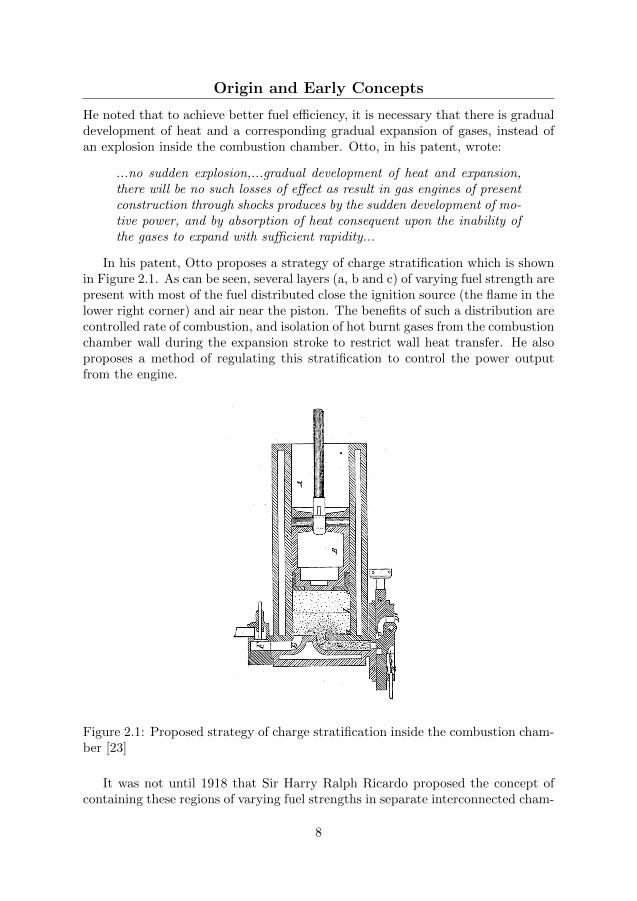
He noted that to achieve better fuel efficiency, it is necessary that there is gradualdevelopment of heat and a corresponding gradual expansion of gases, instead ofan explosion inside the combustion chamber. Otto, in his patent, wrote:
...no sudden explosion,...gradual development of heat and expansion,there will be no such losses of effect as result in gas engines of presentconstruction through shocks produces by the sudden development of mo-tive power, and by absorption of heat consequent upon the inability ofthe gases to expand with sufficient rapidity...
In his patent, Otto proposes a strategy of charge stratification which is shownin Figure 2.1. As can be seen, several layers (a, b and c) of varying fuel strength arepresent with most of the fuel distributed close the ignition source (the flame in thelower right corner) and air near the piston. The benefits of such a distribution arecontrolled rate of combustion, and isolation of hot burnt gases from the combustionchamber wall during the expansion stroke to restrict wall heat transfer. He alsoproposes a method of regulating this stratification to control the power outputfrom the engine.
Figure 2.1: Proposed strategy of charge stratification inside the combustion cham-ber [23]
It was not until 1918 that Sir Harry Ralph Ricardo proposed the concept ofcontaining these regions of varying fuel strengths in separate interconnected cham-
8

Origin and Early Concepts
bers within the engine’s combustion chamber [24]. He noted that with real workingfluids, the specific heat (not the ratio) increases with an increase in temperaturewhich results in less heating of working fluid by a unit fuel energy release. It istherefore of interest to keep the temperature during the cycle as low as possiblewhich also reduces heat losses. An important motivation behind this inventionwas to enable quantity governing (diesel-like) in spark ignited engines and avoidthe throttle and associated losses.
Figure 2.2 shows the layout of the first pre-chamber engine, the Ricardo ThreeValve Engine. In this design, only air was inducted in the main combustion cham-ber (B) through the main intake valve (D), whereas a fuel and air mixture wasinducted in the pre-chamber (G) through the third valve (H). The power out-put from the engine was governed by controlling the quantify of the fuel and airmixture inducted in the pre-chamber, while the mass of air inducted in the mainchamber was unaffected, hence eradicating throttling losses.
Figure 2.2: The layout of Riccardo’s Three Valve Pre-chamber engine [24]
Following Ricardo’s invention of the three valve engine, several other conceptsalong similar lines were proposed over the following decades. C. E. Summers [25]proposed an engine concept with a pre-chamber where the interconnecting channelwas large enough for flames to be ejected into the main chamber. The pre-chamberwas designed to assist this flame travel by inducing swirling motion. On the otherhand, Marion Mallory [26] proposed the use of extremely small nozzle diametersuch that there is sufficient pressure build-up inside the pre-chamber causing highvelocity jets, which he claimed are more efficient in igniting a fuel-lean chargein the main chamber. Later, A. Bagnulo [27, 28] proposed a design with chargestratification even inside the pre-chamber to control the rate of energy release in
9

The L.A.G. Ignition Process
the pre-chamber. N. O. Broderson [29] proposed a design in which the pre-chambervolume was almost half of the engine’s compression volume; and proposed differentfueling strategies to control the power output from the engine. R. M. Heintz [30]proposed the use of a stand pipe, a pipe extending from the pre-chamber nozzleup to the spark plug electrode gap, in an attempt to reduce spark plug fouling dueto deposits which was then common with pre-chamber engines. He also proposeduse of tangentially drilled nozzle holes to induce a swirling motion inside the pre-chamber to improve mixing and reduce fuel-rich zones which contribute to deposits.
The developments in pre-chamber engines until around 1965 were, with someexceptions, based on the strategy of forming a close to stoichiometric mixtureinside the pre-chamber at the time of spark while the main chamber was fuel-lean.The pre-chamber nozzle diameters were set such that the jets are of sufficientlyhigh velocity promoting turbulent mixing in the main chamber. The ignition inthe main chamber therefore relied on the high temperature of the stoichiometriccombustion products from the pre-chamber and turbulent mixing in the mainchamber.
2.2 The L.A.G. Ignition Process
A conceptually new way of operating a pre-chamber engine was developed in 1966,when a Russian scientist called Goossak Lev Abramovich (L. A. Gussak), proposed[31] the use of a very rich mixture (λ = 0.4-0.7) in the pre-chamber to produce alow temperature torch of incomplete combustion products (not a flame) containingchemically active species/atoms like CO, H2, aldehyde and peroxide. This conceptwas called ’Lavinia Aktyvatsia Gorenia’ in Russian and hence is generally referredto as the LAG-Ignition process.
Gussak conducted several studies to understand the effect of fuel rich com-bustion in the pre-chamber on the main chamber combustion. He convincinglydemonstrated the benefits of the fuel rich pre-chamber combustion strategy andwhile reproducing all of his important results here is not feasible, some of the keyresults are discussed in this section.
Figure 2.3 shows the effect of pre-chamber excess air ratio (denoted by α in thisplot) on the flammability limit of the main combustion chamber for stationary flowexperiments [32]. Another parameter used in the plot is δP , which is defined suchthat δP = 0 means that there is no pressure build-up in the pre-chamber, and δP =1 means infinite pressure build-up in the pre-chamber. Practically, δP is inverselyproportional to the nozzle diameter, that is, a smaller nozzle diameter tends toincrease δP . In Figure 2.3, there are two curves for a given value of δP , eachcorresponding to the extremities of the flammability limit in the main combustionchamber. One of the main observations from the plot is the apparent widening ofthe main chamber flammability limit as the mixture in the pre-chamber becomesfuel rich, specifically between αpc of 0.5 and 0.8. Another important observationfrom this plot is that the flammability limit widens when δP increases from 0.2
10

The L.A.G. Ignition Process
Figure 2.3: Effect of pre-chamber mixture strength of various operating parametersof a pre-chamber [32]
to 0.3, but then shrinks when δP is further increased to 0.7. This was a veryimportant finding because most of the earlier pre-chamber concepts deliberatelyused small nozzle diameters to increase the jet velocity.
The combustion temperature inside the pre-chamber is also plotted in figure2.3, which shows that the temperature peaks when the mixture inside the pre-chamber is slightly richer than stoichiometric, and reduces as the mixture becomesfuel rich. A practical implication of this finding is the reduction of NOx formationinside the pre-chamber.
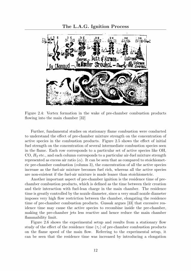
The reason behind the observed effect of nozzle diameter was explained bysome fluid dynamic aspects of the interaction between the pre-chamber jets andthe main chamber charge. Figure 2.4 shows the effect of δP on the resulting vortexformation in the main chamber. It can be seen, and expected, that the mixingvortices become smaller with an increase in δP , and Gussak argues that below acritical size, the vortices are unable to serve as sites for mixing and ignition in themain chamber. Hence a δP greater than a critical value reduces the flammabilitylimit of the main chamber.
11
The L.A.G. Ignition Process
Figure 2.4: Vortex formation in the wake of pre-chamber combustion productsflowing into the main chamber [32]
Further, fundamental studies on stationary flame combustion were conductedto understand the effect of pre-chamber mixture strength on the concentration ofactive species in the combustion products. Figure 2.5 shows the effect of initialfuel strength on the concentration of several intermediate combustion species seenin the flame. Each row corresponds to a particular set of active species like OH,CO, H2 etc., and each column corresponds to a particular air-fuel mixture strengthrepresented as excess air ratio (α). It can be seen that as compared to stoichiomet-ric pre-chamber combustion (column 3), the concentration of all the active speciesincrease as the fuel-air mixture becomes fuel rich, whereas all the active speciesare non-existent if the fuel-air mixture is made leaner than stoichiometric.
Another important aspect of pre-chamber ignition is the residence time of pre-chamber combustion products, which is defined as the time between their creationand their interaction with fuel-lean charge in the main chamber. The residencetime is greatly controlled by the nozzle diameter, since a very small nozzle diameterimposes very high flow restriction between the chamber, elongating the residencetime of pre-chamber combustion products. Gussak argues [33] that excessive res-idence time may cause the active species to recombine inside the pre-chamber,making the pre-chamber jets less reactive and hence reduce the main chamberflammability limit.
Figure 2.6 shows the experimental setup and results from a stationary flowstudy of the effect of the residence time (τr) of pre-chamber combustion productson the flame speed of the main flow. Referring to the experimental setup, itcan be seen that the residence time was increased by introducing a elongation
12

The L.A.G. Ignition Process
Figure 2.5: Streak photographs of stationary flame combustion - effect of fuelstrength [32]
13

The L.A.G. Ignition Process
Figure 2.6: The experimental apparatus and the investigation results of the de-pendence of the turbulent combustion rate Ut on the stationary flow velocity Wf
of the main mixture for different residence time of the pre-chamber combustionproducts and different pre-chamber mixture strengths [33]
pipe between the pre-chamber and the main flow. In the plot to the right, theturbulent combustion rate (Ut) is plotted against the stationary flow velocity (Wf )so that when the combuston rate equals the flow rate, the test point will fall onthe line marked Ut = Wf . On the other hand, as the combustion rate lags behindthe flow velocity, the test point lie in the area below that line. This plot is hencea measure of turbulent flow velocities achievable in the main flow for the givenpre-chamber setting of mixture strength and residence time.
It can be seen from the plot that for ignition without a pre-chamber, a combus-tion rate of only 100 m/s is possible, after which the flame does not stabilize. Forignition with a pre-chamber, there are two other groups of curves in the plot, onefor long residence time (τr = 12.5 ms) and the other one for a short residence time(τr = 6.6 ms). For each group, the pre-chamber mixture strength has been variedfrom close to stoichiometric to extremely fuel rich (αpc = 0.4). It can be seenthat out of the two groups, the group with the shorter residence time is capable ofstabilizing at much higher combustion rates of up to 200 m/s, whereas for the longresidence time cases, the maximum combustion rate is restricted to around 150m/s. Furthermore, for each residence time group, lower αpc is capable of highercombustion rates in the main flow. This plot hence highlights the importance ofresidence time, and proves that fuel rich combustion in the pre-chamber alone doesnot guarantee improved ignition performance in the main chamber. The residencetime, which is mainly affected by the nozzle diameter as discussed earlier, is alsoequally important.
14

Modern Systems
2.3 Modern Systems
Alongside the development of the LAG-process of ignition, the pre-chamber igni-tion system found extensive commercial application in light duty engines, intro-duced primarily to reduce exhaust emissions with the fuel efficiency improvementsbeing an additional advantage.
In the wake of the findings by Gussak on the importance of residence time,Newhall et. al. [34] developed a pre-chamber engine with the spark plug placedclose to the interconnecting channel between the pre- and the main chamber. Bythis arrangement, the combustion products are directly discharged into the mainchamber as the combustion proceeds towards the inner end of the pre-chamber.However, from the results presented, no significant benefits in terms of poweroutput or fuel efficiency were found.
In 1975, Honda developed a combustion concept termed Compound VortexControlled Combustion (CVCC) using pre-chamber ignition with additionalfueling. The particularity of the CVCC concept was three (or more) levels ofstratification in the combustion chamber. The pre-chamber was deliberately over-fueled such that some of the fuel flows out of the pre-chamber. This over-flown fuelpartially mixted with the main chamber charge during the compression stroke, butalso formed a comparatively fuel-rich cloud of mixture around the pre-chambernozzles. This formed three layers of stratification, first the pre-chamber beingextremely fuel rich, then the fuel rich mixture cloud surrounding the pre-chamberand finally the fuel-lean charge further out in the main chamber. It was arguedthat this fuel-rich cloud provides a favorable environment for the pre-chamber jetsto ignite the main chamber charge. The CVCC design demonstrated very lowengine-out emissions and also high fuel efficiency.
Several other light duty pre-chamber engines were developed, like the PorscheSKS engine [35] and the Volkswagen PCI [36] with some particularities of theirown but are not discussed further here.
Another major pre-chamber initiated combustion concept was developed byOppenheim et. al. [37] during late 1980s under the name of Pulsed Jet Com-bustion (PJC). In his patent, he states that:
...shortcomings of similar devices of the prior art is that they are notcapable of furnishing the required plumes capable of entraining asufficient amount of the compressed charge so that ignitionand subsequent combustion occur in the interior of the eddiesof which the plumes are formed, but essentially ignite the main chargeby establishing too readily the conventional flame fronts which traversethe charge at their own normal burning speed...
It is clear that in PJC, the pre-chamber was not just used as an ignition sourcefor the main chamber charge, but the concept required formation of large mixingeddies or plumes within which the main chamber charge is consumed. Experiments
15

Modern Systems
with the PJC system [38, 39, 40] showed that the dilution limit was only marginallyextended from λ = 1.66 to 1.81. The fuel efficiency improved while the HC andCO emissions increased.
Considering very recent developments, in 2003, General Motors developed thePremixed Charge Forced Auto-ignition (PCFA) ignition concept that operated ina dual mode combustion system, with pre-chamber ignition at low load and con-ventional spark ignition at high load to avoid excessive pressure rise rates [41].In 2005, Robert Bosch GmbH developed the Homogeneous Combustion Jet Igni-tion (HCJI) system [42] in which ignition inside the pre-chamber was achieved byauto-ignition by timely compression of pre-chamber charge by a separate piston.No published results of the performance of this system were found. In 2007, IAVGmbH and MULTITORCH GmbH developed pre-chamber spark plugs with pilotinjection [43] demonstrating injection of hydrogen as pre-chamber fuel to furtherextend the dilution limit of the main chamber from λ = 1.7 to 2.
And finally, the most recent developments of commercial pre-chamber ignitionsystems have been done by Mahle Powertrain, under the name of Turbulent JetIgnition – TJI [44]. Published studies with the TJI [45, 46] have shown extensionof dilution limit excess air to around λ = 2. It was also demonstrated that the TJIsystem is capable of stable operation with extremely low ignition energies (10mJ)as compared to conventional spark ignition system which required a minimumenergy of 40mJ at identical operating conditions.
The exact strategy of operation of these modern pre-chamber ignition systemsis not explicitly published but most of them are reportedly operated with a stoi-chiometric or a slightly fuel rich (0.9 < λ > 1) mixture in the pre-chamber, andmost of the published results are at low load operation in light duty engines.
It has been shown that pre-chamber ignition systems have undergone continu-ous development during the last century, but has not received as much attentionas the other popular alternative to spark ignition, diesel pilot injection. Thiscan partially be explained by the complex nature of the ignition resulting from apre-chamber ignition system. To conclude this chapter, a quote from Sir HarryRicardo’s patent in 1918 [24] is reproduced below, which adequately summarizesthe delicacy of pre-chamber ignition systems.
...if not just right, it may be very wrong; a very small change in formor dimension may upset the whole system...
– Sir Harry R. Ricardo
16
Chapter 3
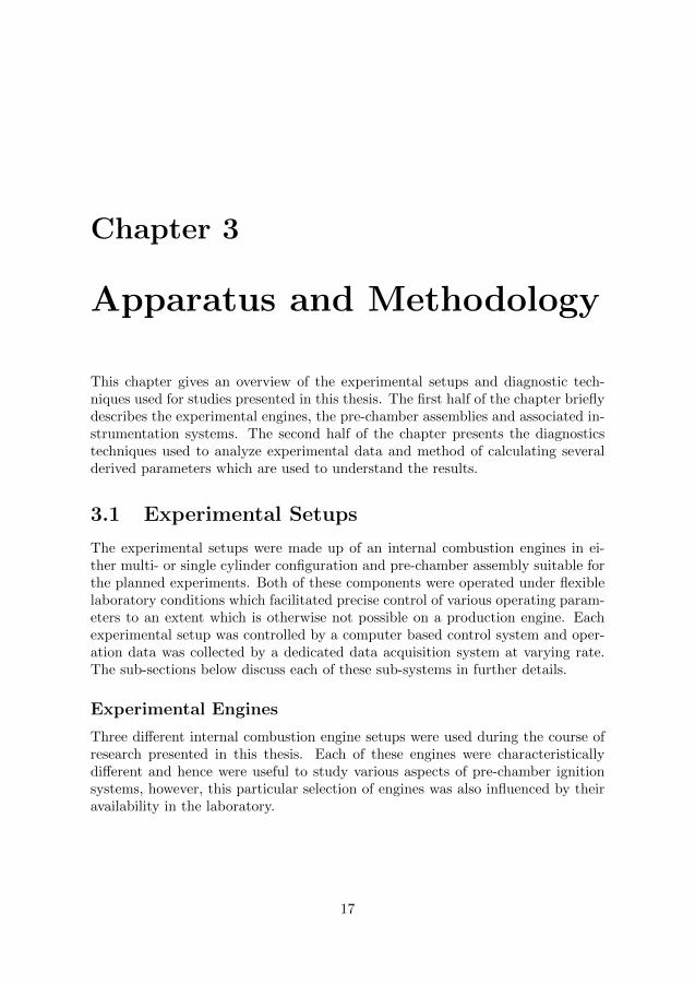
Apparatus and Methodology
This chapter gives an overview of the experimental setups and diagnostic tech-niques used for studies presented in this thesis. The first half of the chapter brieflydescribes the experimental engines, the pre-chamber assemblies and associated in-strumentation systems. The second half of the chapter presents the diagnosticstechniques used to analyze experimental data and method of calculating severalderived parameters which are used to understand the results.
3.1 Experimental Setups
The experimental setups were made up of an internal combustion engines in ei-ther multi- or single cylinder configuration and pre-chamber assembly suitable forthe planned experiments. Both of these components were operated under flexiblelaboratory conditions which facilitated precise control of various operating param-eters to an extent which is otherwise not possible on a production engine. Eachexperimental setup was controlled by a computer based control system and oper-ation data was collected by a dedicated data acquisition system at varying rate.The sub-sections below discuss each of these sub-systems in further details.
Experimental Engines
Three different internal combustion engine setups were used during the course ofresearch presented in this thesis. Each of these engines were characteristicallydifferent and hence were useful to study various aspects of pre-chamber ignitionsystems, however, this particular selection of engines was also influenced by theiravailability in the laboratory.
17

Experimental Setups
Volvo Multi-cylinder Engine
This engine was originally a 6 cylinder, 9.4 L diesel engine from Volvo Truckswhich was modified to operate in spark ignition mode using natural gas as fuel un-der a reduced compression ratio of 12:1. The engine was equipped with a variablegeometry turbocharger, a long route cooled EGR system, a multi-point gas injec-tion system and an inductive type ignition system. Pistons with Quartette typecombustion chamber design, which is known to generate high level of turbulenceto enhance lean combustion [47], were used. This was the first and only enginesetup that closely resembled a production engine and hence was used to performrelatively applied research studies with pre-chamber spark plugs. Further detailsabout this engine can be found in Paper I.
Scania Single-cylinder Engine
This engine was a 6-cylinder heavy duty diesel engine from Scania which wasmodified to operate with one active cylinder of 2.12 L displacement volume. Theremaining cylinders were motored without compression. The compression ratio ofthe active cylinder, which originally was 17.3:1, was reduced to 12:1 by introducinga spacer of appropriate thickness between the engine block and cylinder head.The original piston with a shallow bowl-in-piston design of combustion chamberwas used. Natural gas fuel injectors were installed in the intake manifold formain chamber fueling and an inductive type ignition system with variable dwelltime control was installed. A high pressure (10 bar-a) air reservoir fed the enginethrough a pressure regulator to adjust the intake pressure to the desired level. Thissingle cylinder engine setup was prepared specifically for fundamental studies tounderstand the mechanism of pre-chamber ignition with auxiliary fueling. Specialarrangements were made to accurately measure the air and gas flow to the enginethough both the main and pre-chamber to calculate the excess air ratios in bothchambers at the time of ignition. Further details can be found in Papers III & IV.
Wartsila Single-cylinder Engine
This engine was a large bore, medium speed, 6-cylinder Diesel-Natural Gas dualfuel engine from Wartsila which was modified to operate with one active cylinderof 8.8 L displacement volume, while the remaining cylinders were motored withoutcompression. The geometrical compression ratio of the active cylinder was 13:1but as the engine employed early intake valve closure strategy (Miller timing),the volumetric compression ratio was approximately 12:1. The original pistonwith an open combustion chamber design was used. Most of the other air supplyarrangements were similar to those for the Scania engine but scaled up as necessary.One particular difference, however, was that the main gas admission valve onthis engine required a pressure drop of less than 2 bar, and hence a pressureregulator was used in the main gas supply line. This pressure regulator was PIDcontrolled for real time adjustments of the supply pressure depending on the intake
18

Experimental Setups
manifold pressure so that the quantity of gas injected for a set injection durationis unaffected. Most of the pre-chamber related arrangements were the same as forthe Scania engine setup. Further details can be found in Paper VI.
Pre-chamber Assemblies
The pre-chamber assemblies, some bought from the market and others designedand manufactured in-house, were prepared to suit the engine and the experimentsperformed using them. Hence, three different pre-chamber assemblies were usedin total out of which the first type used with the Volvo engine were bought fromthe market and were the simplest. They did not have any arrangements for ad-ditional fueling and were installed in place of the conventional spark plug hencerequiring no modification to the engine. The pre-chamber assemblies used with theScania and the Wartsila engines were custom made to suit the respective engine.They were also much more versatile and flexible with the parameters of interestin experiments.
Pre-chamber Spark Plugs
Pre-chamber spark plugs were used with the multi-cylinder Volvo engine for thestudies presented in Papers I and II. They were produced by Multitorch GmbHin Germany and were bought off the shelf. A pre-chamber spark plug was essen-tially a conventional spark plug, with a hemispherical pre-chamber welded on itstip. An important difference, however, is that 4 pin-like arms extend out of thecentral electrode with their tips extending to the pre-chamber wall (ground elec-trode) forming a spark gap of approximately 0.3 mm. The pre-chamber volumewas approximately 0.2 cm3, which amounts to 0.141 % of the engine’s clearancevolume. Each pre-chamber had 5 nozzles of 1.1 mm diameter. For the set of exper-iments conducted with this pre-chamber and the Volvo engine, the pre-chambervolume and nozzle diameter settings were not specifically controlled since it wasnot required by the experiments. Pre-chamber spark plug nozzle orientation withrespect to the combustion chamber cavity (Quartette design) was kept identicalduring all experiments. This pre-chamber spark plug was operated with the samespark ignition system used with conventional spark plugs during the experiments.Further details of the pre-chamber spark plugs can be found in Papers I and II.
Pre-chamber Assembly for the Scania Engine
As discussed earlier, the experiments conducted with the single cylinder Scaniaengine were relatively fundamental in nature and hence required a versatile andflexible pre-chamber assembly. Therefore, a pre-chamber assembly capable of fuelinjection, spark ignition and pressure measurement was designed and manufac-tured. The assembly mainly comprised two parts, the pre-chamber head on whichthe required instrumentation was installed, and the pre-chamber body which could
19

Experimental Setups
be changed to change the pre-chamber volume. Two major experimental cam-paigns were conducted using the Scania engine and hence two versions of theScania pre-chamber assembly were also prepared. They were essentially the sameexcept for the use of a bigger spark plug (M10 instead of M8) and water cooledpressure sensor on the second version to overcome problems faced with the firstversion.
Fuel delivery into the pre-chamber was achieved using a miniature check valve,which was fed with natural gas at the desired injection time by a solenoid operatedgas injector. Gas was supplied from high pressure (up to 200 bar) natural gasstorage cylinders through a pressure regulator with manual control of downstream(pre-chamber injection) pressure of up to 25 bar-a. The mass flow rate of gas to thepre-chamber was measured using a thermal mass flow meter. Two surge tanks, of 2liters each, were installed before the fuel injectors to isolate the pressure regulatorand more importantly the flow meters from the pressure fluctuations caused byperiodic injection of gas in the pre-chamber.
Apart from the gas injection valve, a spark plug and a pressure sensor was in-stalled in the pre-chamber head. The relative positioning of these components wasgoverned mainly by availability of space, but it was an intended design objectiveto place the spark plug closest to the center, and it was finally placed with a 2mmoffset from the center axis. This was done to promote flame propagation in all di-rections so that most of the pre-chamber charge is consumed before the back-flowof charge from the main chamber occurs, and hence reduce unburnt hydrocarbonemissions due to incomplete combustion in the pre-chamber. This is one of themajor design peculiarities as compared to other similar pre-chamber designs whichcan be found in literature [48].
For the first version of the pre-chamber assembly, which was used to studythe fuel-rich pre-chamber combustion strategy (LAG process), the pre-chambervolume and nozzle diameter were set as close as possible to the recommendationsby Gussak et. al [49] for the LAG process. Total number of nozzles were set to 8for good spatial distribution of igniting jets ejected from the pre-chamber. Thisis also done to have a diesel-like initiation of combustion in the main chamberas the original diesel piston was used and the stock diesel injector for the Scaniaengine had 8 nozzles. The nozzles were drilled normal to the pre-chamber surfacehence not contributing to formation of swirl due to in flow of charge during thecompression stroke. The pre-chamber cone angle was set to 130◦ so that thenozzles are targeted to the same point of the piston bowl as by the diesel injectornozzles with a cone angle of 148◦ (geometrically).
Realizing the drawbacks of using an 8mm spark plug and an uncooled pressuresensor in the first version of the pre-chamber assembly, the second version wasredesigned and built with a high performance M10 iridium tip spark plug anda water-cooled piezoelectric pressure transducer. This pre-chamber version wasused for the experimental campaign to study effect of pre-chmaber volume andnozzle diameter in which 3 different pre-chamber volumes were tested. All thesevariations were achieved by changing the geometry of the internal cavity while
20

Experimental Setups
maintaining the same external dimension of the pre-chamber body, hence enablingthe use of the same pre-chamber head and instrumentation set. Further details ofeach version of the Scania pre-chamber assembly can be found in Papers III andIV.
Pre-chamber Assembly for Wartsila Engine
The pre-chamber assembly designed for the Wartsila engine was conceptually sim-ilar to the one used in the Scania engine, except for the modifications required tosuit the much larger cylinder head of the Wartsila engine. The assembly wascompletely redesigned externally to mimic the external dimensions of the engine’sstock diesel injector. Further, due to the design of the cylinder head, the heightof the pre-chamber body had to be increased but the ratio of the height of thepre-chamber body in the Scania and the Wartsila engine was the same as the ratioof cylinder bores of the engines. Another notable difference in this pre-chamberassembly was that the pre-chamber head was manufactured of Bronze while allother components in the assembly were made of stainless steel. This was done toovercome the thread-locking problem previously encountered in the Scania pre-chamber assembly since all components were made out of stainless steel. Thisassembly was used in an experimental study on scalability aspects of pre-chamberignition and the dependency of performance of a pre-chamber of a given volume onthe displacement volume of the engine. Thus, similar to the Scania pre-chamberassembly, three pre-chamber bodies with different internal volume were manufac-tured. Further details about the design of the Wartsila engine pre-chamber canbe found in Paper VI.
Control and Data Acquisition System
Although three different engine setups were used, the architecture of their controland data acquisition system were essentially the same.
As illustrated in Figure 3.1, all control and data acquisition tasks were handledby a single computer which interacted with the test engine via three communica-tion channels. The first channel was the high-speed data acquisition and controlsystem card which was used for high speed (crank angle resolved) data acquisitionfrom sensors for in-cylinder pressure, fast intake and exhaust manifold pressureetc., and also send signals to various controllers for gas injection, ignition, pres-sure regulators etc. For the multi-cylinder Volvo engine setup, the master PC wasbased on the GNU/Linux operating system and an in-house developed C++ basedcontrol and data acquisition system called ’DAPMEAS’ was used. A Microstar5400A (DAP 5400A) was used for all high speed DAQ and control purposes. Forthe Scania and the Wartsila engine setups, the control computer was MicrosoftWindows based and a LabVIEW based control and data acquisition system wasused. This LabVIEW based system comprised the main host computer and a tar-get computer running LabVIEW real-time operating system with a PCIe-7842R
21

Experimental Setups
Multifunction RIO (Reconfigurable Input/Output) card.
���������
�� �����
���������
��������
���������
�� �����
�����������
�������
������
Figure 3.1: General layout of experimental setup.
The second communication channel was the low speed data acquisition systemwhich operated at a data logging frequency of 1-3 Hz (depending on number ofchannels in use) and was used to record signals from various system level sensorsfor coolant temperature, lubricating oil temperature and pressure, intake air andgas flow rates, Lambda sensor etc. In all the engine setups, this function wasaccomplished using Agilent Technologies’ 34970A Data Acquisition Unit capable ofoperating with 3 units of a 20 channel multiplexer card. This data acquisition unitcommunicated directly with the control computer (host computer) via a TCP/IPcommunication protocol and data was directly read by the main measurement andcontrol program.
The third channel of communication was with the emission system which feddata on concentration of CO, CO2, THC, NOx and O2 (Only in Engine setup 2)in the engine’s exhaust. The measurement technique used for each of these speciesis detailed in table 3.1. The EGR rate was calculated by measuring the CO2 inthe intake and exhaust manifold. Data from the emission system was first fed toan intermediate server which then communicated with the main control computervia TCP/IP communication protocol.
Table 3.1: Measurement Techniques for different emission species
Species Measurement Technique RangeCO2, CO Non-Dispersive Infrared Detectors (NDIR) 0-15 %, 0-10000 ppmTHC Flame Ionization Detector (FID) 0-4000 ppmNOx Chemiluminescence Detector (CLD) 0-10000 ppmO2 Paramagnetic Detector (PMA) 0-25 %
22

Diagnostic Techniques
3.2 Diagnostic Techniques
Several diagnostic techniques were used to analyze the data collected during ex-periments to understand the behavior of the in-cylinder combustion. This sectionbegins by discussing the efficiency of various stages in which the fuel energy isconverted into mechanical work in an internal combustion engine. The efficiencyparameters which are extensively used during the studies presented in this the-sis are then discussed in detail. The next diagnostic technique presented in thein-cylinder heat release analysis is based on the measured cylinder pressure. Andfinally, the method for estimating the excess air ratio inside the pre-chamber isbriefly discussed.
Efficiency Parameters
An internal combustion engine is a heat engine which converts a fuel’s chemicalenergy into mechanical work. In a reciprocating type engine operating on a 4-stroke cycle [50], like all engines used for studies presented in this thesis, thisconversion happens in several stages which are depicted in a Sankey diagram inFigure 3.2. The text on the right hand side describes the flow of energy througheach of these stages, presented as Mean Effective Pressure (MEP) which is definedas the work or energy per cycle normalized by the engine’s displacement volume.
Figure 3.2: The Energy Cascade in anInternal Combustion Engine
FuelMEP: Energy contained by the fuel- QemisMEP: Chemical energy lost dueto incomplete combustion= QhrMEP: Chemical energy releasedin the combustion chamber- QhtMEP/QexhMEP: Energy (heat)lost by heat transfer and exhaust= IMEPgross: Energy (mechanicalwork) transfered to the piston over com-pression and expansion strokes- PMEP: Energy (mechanical work) lostin pumping work= IMEPnet: Energy (mechanical work)transferred to the piston over the entire4 stroke cycle- FMEP: Energy (mechanical work) lostin overcoming mechanical friction= BMEP: Energy (mechanical work)available at the output shaft
23
Diagnostic Techniques
As can be seen in the energy cascade, some amount of energy is lost in eachstage and hence efficiency parameters are defined to evaluate each stage individ-ually. The definition of selected efficiency parameters which are of importance tothe following chapters are reproduced here.
Combustion Efficiency
The first stage is the combustion of fuel with an oxidizer during which the fuel’schemical energy (FuelMEP) is released in the form of heat in the combustion cham-ber (QhrMEP). The energy lost in this stage is expelled out of the combustionchamber as partially or completely unburnt fuel (QemisMEP), which can be esti-mated from the measured emission species like HC and CO in the engine exhaust.The efficiency of this stage is hence called Combustion Efficiency and is expressedby equation 3.1.
ηc =
(QhrMEP
FuelMEP
)= 1−
(QemisMEP
FuelMEP
)(3.1)
where, the various MEP values are calculated by normalizing the associated energyvalues by the engine displacement volume. As an example, equation 3.2 is anexpression to calculate FuelMEP.
FuelMEP =
(mf ·QLHV
VD
)(3.2)
where mf is the mass of fuel per cycle, QLHV is the lower heating value of thefuel and VD is the engine’s displacement volume.
Thermodynamic Efficiency
The next stage is the conversion of heat released in the combustion chamber(QhrMEP) into mechanical work transfer to the piston during the expansion phaseof the cycle. This stage usually contributes to the biggest energy loss in the entireprocess. As also shown in figure 3.2, energy loss during this stage is due to heattransfer (QhtMEP) and sensible heat of exhaust gases (QexhMEP).
The mechanical work transfer to the piston is calculated using the measuredcylinder pressure and the cylinder volume calculated using the crank slider mech-anism equations as discussed in [50]. The mechanical work transfer during thecompression and expansion stroke is expressed as IMEPg and that transferredover all 4 strokes is expressed as IMEPn, as shown in equations 3.3 and 3.4,respectively.
IMEPg =
∫ 180
−180p · dv
VD(3.3)
24
Diagnostic Techniques
IMEPn =
∫ 360
−360p · dv
VD(3.4)
It can be noted that these definitions are based on fixed crank angle durationsaround the firing top dead center, and not on the valve timings of individualengines. Now, using these definitions, the thermodynamic efficiency is calculatedby equation 3.5.
ηth =
(IMEPg
QhrMEP
)= 1−
(QhtMEP +QexhMEP
FuelMEP
)(3.5)
Indicated Efficiency
The indicated efficiency is the efficiency of both the previously discussed stagescombined. Two indicated efficiencies can be defined, gross and net, by calculatingwith the corresponding IMEP values. The gross indicated efficiency can thereforebe expressed as equation 3.6.
ηg,i = ηc · ηth =
(IMEPg
FuelMEP
)(3.6)
Combining equations 3.6 and 3.2, the gross indicated efficiency can be expressedas equation 3.7 which can be calculated using experimentally measured variables.
ηg,i =
IMEPg(mf ·QLHV
VD
) (3.7)
The net indicated efficiency can be calculated in a similar way but will not bediscussed here in detail as it has not been used in the presented studies.
Brake Efficiency
The brake efficiency is the efficiency of the entire energy cascade shown in figure3.2, which accounts for all chemical, heat and friction losses in the engine. Thisparameter is therefore only calculated for the first experimental setup which wasa multi-cylinder engine and whose mechanical power output was recorded. Thebrake efficiency is calculated by equation 3.8.
ηb =
(BMEP
FuelMEP
)(3.8)
25

Diagnostic Techniques
Heat Release Analysis
Heat release analysis is a diagnostic tool used to understand the rate and extent ofthe chemical energy release in the combustion chamber. Since this energy releasegenerally happens during the closed part of the 4 stroke cycle (when valves areclosed), the combustion chamber can be considered as a thermodynamically closedsystem, assuming that mass flow across system boundaries due to blow-by etc. isnegligible. Given the instantaneous cylinder pressure and volume data, the firstlaw of thermodynamics can be used to calculate the rate of energy addition to thesystem due to combustion. This calculation is presented at length in [50], and thefinal heat release equation can be expressed as equation 3.9
dQnet
dθ=
γ
γ − 1· p · dV +
1
γ − 1· V · dp (3.9)
where Q is the energy released, γ is the instantaneous ratio of specific heat of thesystem of gases, p is the cylinder pressure and V is the cylinder volume. It shouldbe noted that this equation yields the energy release excluding the energy lost dueto heat transfer, and hence the heat release calculated using equation 3.9 is thenet or apparent heat release.
To calculate gross heat release, the heat transfer was modeled as steady flowforced convection heat transfer to a solid surface and the heat flux is expressed byequation 3.10.
dQht
dt= hc(Tg − Tw) (3.10)
where hc is the heat transfer coefficient, Tg is the instantaneous cylinder gas tem-perature which is estimated using the ideal gas law, and Tw is the cylinder walltemperature. Several models exist for estimating the heat transfer coefficient andthe model proposed by G. Woschni [51] was adopted for all calculations presentedin this thesis. The heat transfer coefficient according to Woschni’s model is givenby equation 3.11.
hc = 3.26 ·B−0.2 · p0.8 · T−0.55 · w0.8 (3.11)
where B is the cylinder bore, p is the instantaneous cylinder pressure expressed inkPa (unlike all other variables which are expressed in the SI system of units), T iscylinder temperature and w is the average cylinder gas velocity which is expressedby equation 3.12
w =
[C1 · Sp + C2 ·
VD · Trpr · Vr
· (p− pm)
](3.12)
where Sp is the mean piston speed, pr, Vr, Tr are the working fluid pressure, volumeand temperature respectively at some reference state (intake valve closure), andpm is the motored cylinder pressure at the same crank angle as p.
26

Diagnostic Techniques
The constants C1 and C2 used in equation 3.12 take different values duringdifferent periods of the cycle as given below.
Gas exchange period: C1 = 6.18 + 0.417 · vsSp
C2 = 0
Compression period: C1 = 2.28 + 0.308 · vsSp
C2 = 0
Combustion and expansion period: C1 = 2.28 + 0.308 · vsSp
C2 = 3.28 · 10−3
where vs is the swirl velocity which is a function of ωp, the rotation angular velocityof the paddle wheel used to measure the swirl velocity. Both of these variables aredefined in equations 3.13 and 3.14.
vs =B · ωp
2(3.13)
ωp = Rs · (2 · π ·N) (3.14)
where Rs is the swirl ratio which was a known parameter for all the experimentalengines.
Finally, combining equation 3.9 and equation 3.10 expressed in crank angledegrees, the gross heat release in the main combustion chamber can be expressedby equation 3.15
dQ
dθ=
γ
γ − 1· p · dV +
1
γ − 1· V · dp+
dQht
dθ(3.15)
Model to Estimate Pre-chamber Excess Air Ratio
Tools like an oxygen sensor based Lambda sensing module and analysis of exhaustgases are generally used to estimate the overall air to fuel ratio in the combustionchamber of an engine, which, in an engine using pre-chamber, yields the overallair to fule ratio since it takes into account the total fuel injection in both the mainand pre-chambers. For the studies presented here, it was necessary to estimate theexcess air ratio of each chamber separately. The excess air ratio of the main cham-ber charge (λMC) was therefore calculated from measured air and fuel flow rates,however, direct measurement of pre-chamber excess air ratio (λPC) at the time ofspark ignition is not straight forward as fuel-lean charge from the main chamberis continuously pushed into the pre-chamber during the compression stroke hencediluting the charge therein. Therefore, λPC is calculated from the measured fuelflow rate to the pre-chamber, and the previously calculated excess air ratio of themain chamber. The mass flow of charge into the pre-chamber during the com-pression stroke was calculated by equations for motion of slider crank mechanism.Gussak [49] used such a model but it was applicable for the case where a mixtureof fuel and air is injected in both chambers, whereas in the experiments presentedin this thesis, only fuel was injected in the pre-chamber. Hence a similar modelwas derived and can be found in Paper III.
27

Chapter 4
Experimental Studies
4.1 Un-fueled Pre-chamber studies
The first set of experiments were conducted using the multi-cylinder Volvo enginein which a pre-chamber ignition system without additional fueling (pre-chamberspark plugs) was studied and compared with conventional spark ignition system.The aim was to understand the main chamber ignition characteristics, dilutionlimit, maximum operating load and engine-out emissions with pre-chamber sparkplug (PC.SP) as compared to with conventional spark plugs (C.SP), hereafterreferred to as two cases. Four sets of experiments were conducted and selectedresults are presented here. Detailed results and discussion can be found in PaperI.
Heat Release Characteristics
The intention was to compare main chamber heat release characteristics for thetwo cases at the same operating points with respect to engine speed, load and sparktiming, so as to compare flame development angle and combustion duration whichare indicators of ignition and early flame propagation in the main chamber. Enginewas operated at three speeds – 1200, 1500 and 1800 rpm, and three operating loads– 3, 6 and 9 bar IMEPg, with the spark timing held constant at 12 CAD bTDC forall the points. On this 9 point test matrix, dilution from stoichiometric operation(excess air ratio λ = 1) to the lean limit in steps of 0.1 was studied. This loadrange was selected to avoid the region of operation where the pre-chamber sparkplugs cause charge pre-ignition, which is discussed in a later section.
Figure 4.1 is a plot of flame development angle which is defined as the timeduration, in crank angle degrees, between the beginning of spark discharge and10% accumulated heat release in the main chamber. It can be seen that ignitionwith pre-chamber spark plugs consistently results in shorter flame developmentangles than conventional spark plugs over the entire test matrix. Considering that
28

Un-fueled Pre-chamber studies
Figure 4.1: Flame development angle at 1500 rpm and under various load anddilution levels
the ignition from a pre-chamber spark plug is actually a two-step process, startingwith ignition of charge inside the pre-chamber which results in formation of jetswhich then ignite the charge in the main chamber, it is interesting to note thatthese two steps are completed in less time than ignition with a conventional sparkplug. This shows that multiple jets from a pre-chamber provide much higherignition energy in the main chamber than a single point spark discharge. Thiseffect, however, appears to diminish as the engine operates leaner as can be seenfor the λ = 1.6 case. This can be attributed to over-leaning of the charge insidethe pre-chamber in absence of additional fueling and a scavenging mechanism forthe pre-chamber.
Figure 4.2 presents the comparison of combustion duration which is defined asthe time duration, in crank angle degrees, between 10% and 90% accumulated heatrelease in the main chamber. Unlike flame development angle, the effects of ignitionby a pre-chamber spark plug only become evident as the engine operates leaner.At stoichiometric conditions, both ignition systems result in similar combustiondurations. It is expected that with the pre-chamber spark plug, multiple nozzlesproduce a spatially distributed ignition source resulting in onset of combustionat more than one locations simultaneously and hence the main chamber charge isconsumed in a shorter time. But perhaps this effect is only significant when theengine operates lean with substantially reduced laminar flame speed of the mainchamber charge.
29

Un-fueled Pre-chamber studies
Figure 4.2: Combustion duration at 1500 rpm and under various load and dilutionlevels
Dilusion Limit
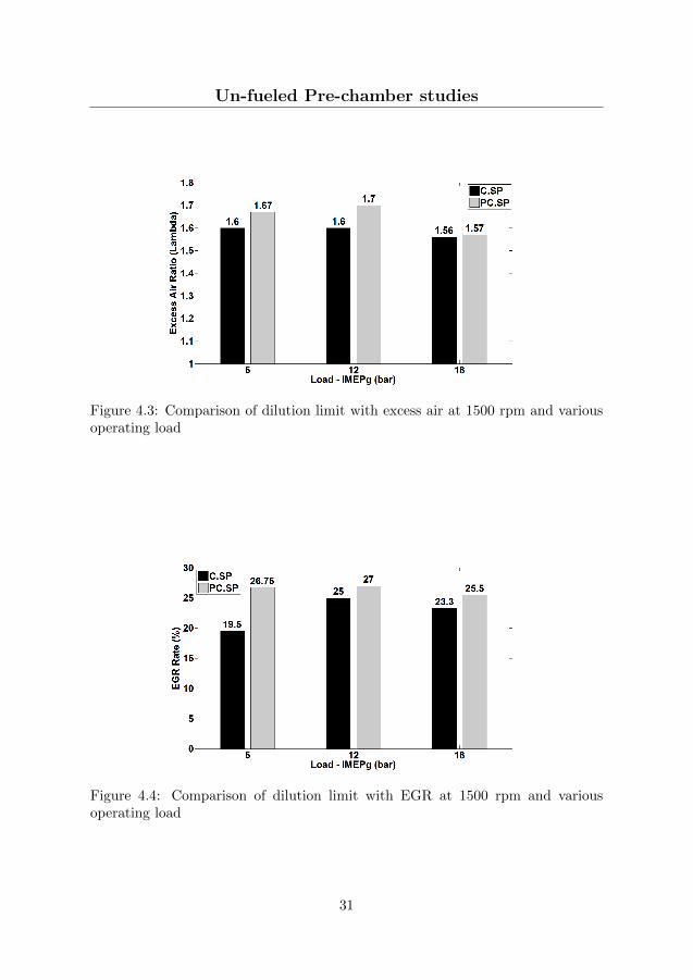
The maximum dilution with excess air and EGR while maintaining acceptablecombustion stability were separately determined for each case. Experiments wereperformed at 1500 rpm engine speed and 5, 12 and 18 bar IMEPg engine loadwith knock limited maximum brake torque (MBT) spark timing for each operatingpoint.
The dilution limit with excess air and EGR are shown in Figures 4.3 and 4.4,respectively. It can be seen that operation with pre-chamber spark plugs onlymarginally extend the dilution limit with excess air and EGR. This can againbe attributed to over-leaning of the charge inside the pre-chamber due to theabsence of a scavenging mechanism for the pre-chamber. At the beginning ofevery cycle, the pre-chamber is filled with residual gases and then fresh charge ispushed into the pre-chamber during the compression stroke. Hence at the time ofspark ignition, the charge inside the pre-chamber is always more diluted than thatin the main chamber. Hence at the lean limit, ignition inside the pre-chamber isitself a challenge.
Before proceeding further, it is important to mention that pre-chamber sparkplugs caused charge pre-ignition at loads exceeding approximately 10 bar IMEPg.It is believed that the pre-chamber surface becomes excessively hot and due toabsence of an effective heat removal mechanism, the surface acts as a hot spotigniting the air-fuel mixture ahead of spark timing, which results in excessivecylinder pressure and unstable combustion. Due to this reason, it was not possibleto operate the engine with stable combustion at loads exceeding 10-12 bar IMEPgwithout any dilution, and hence limited results are available in this regard in thefollowing sections.
30
Un-fueled Pre-chamber studies
Figure 4.3: Comparison of dilution limit with excess air at 1500 rpm and variousoperating load
Figure 4.4: Comparison of dilution limit with EGR at 1500 rpm and variousoperating load
31

Un-fueled Pre-chamber studies
Minimum dilution required
Operating a natural gas engine at stoichiometric air to fuel ratio above certainoperating load causes problems like excessive exhaust gas temperature which isunsuitable for the turbocharger and charge pre-ignition when operating with pre-chamber spark plugs. This means that a minimum amount of dilution, with eitherexcess air or EGR, is always required when operating above a critical engine load,which was found to be in the range of 10 to 12 bar IMEPg for the experimentalengine. This set of experiments served to determine this minimum dilution, whileobserving three main restrictions - exhaust temperature less than 700 ◦C, avoidcharge pre-ignition and maintain combustion stability (COV of IMEPg) below5%.
Figure 4.5 shows the operating windows determined with each ignition system.As can be seen, the minimum dilution required increases with increasing load andthis requirement increases very sharply with pre-chamber spark plug in order toavoid pre ignition. This factor also determines the maximum achievable operatingload where the upper limit of dilution equals the minimum dilution required. Itis interesting to note that the charge pre-ignition problem not only shrinks theoperating window but also restricts the maximum load to 19 and 20 bar IMEPg
with EGR and excess air dilution, respectively. On the other hand, it was possibleto operate at loads up to 22.5 bar IMEPg under excess air dilution with a con-ventional spark plug as the limitation due to excessive exhaust gas temperature iscomparatively less severe. It can hence be concluded that the benefits of slightlyextended dilution limit with pre-chamber spark plugs are offset by the issue ofcharge pre-ignition, and hence the maximum operating load actually decreaseswith pre-chamber spark plug ignition.
Figure 4.5: Comparison of minimum dilution required and available operatingwindow at 1500 rpm
32

Un-fueled Pre-chamber studies
Combustion Stability
One of the benefits of pre-chamber ignition is the isolation of the spark plug frombulk charge motion in the main chamber and hence reduced cyclic variation ofignition and early flame development around the spark plug. A brief study ofcycle to cycle and cylinder to cylinder variations was hence conducted to studythe effect of pre-chamber spark plug on combustion stability. The cycle to cyclevariation is the COV of IMEPg was calculated individually for each cylinder overa sample size of 200 cycles and then averaged, whereas the cylinder to cylindervariation is the COV of IMEPg between the 6 cylinders calculated individuallyfor each cycle and then averaged over 200 cycles. As can be seen in Figure 4.6,both combustion variability parameters are lower for operation with pre-chamberspark plugs, with the difference being very significant near the dilution limit. Thisdata proves that while the consistency of ignition with a conventional spark plugis highly affected by in cylinder flow characteristics and turbulence, ignition insidethe pre-chamber and the following spatially distributed jets are less affected byin-cylinder flow characteristics.
(a) Cycle to Cycle variations
(b) Cylinder to Cylinder variations
Figure 4.6: Coefficient of variation in IMEPg at 1500 rpm, 12 bar IMEPg anddilution with excess air
33

Un-fueled Pre-chamber studies
Figure 4.7 shows the COV in IMEPg under EGR dilution conditions. Similartrends of better combustion stability with pre-chamber spark plug is visible alsowith EGR dilution, and are due to the reasons discussed above.
(a) Cycle to Cycle variations
(b) Cylinder to Cylinder variations
Figure 4.7: Coefficient of variation in IMEPg at 1500 rpm, 12 bar IMEPg anddilution with EGR
From these results, it was clear that using a pre-chamber spark plug providesa more effective ignition source and also improves combustion stability, that is,the benefits of isolating the ignition source from main chamber charge motion andproviding a spatially distributed ignition source were evident. However, in absenceof additional fueling and hence over-leaning of charge inside the pre-chamber, therewas only a marginal extension of the dilution limit with excess air and EGR.This restricts the use of pre-chamber ignition to achieve better efficiency andalso restricts the maximum operating load. These results hence motivated thesubsequent set of experiments to evaluate pre-chamber ignition with additionalfueling.
34

Fueled Pre-chamber studies
Ion Currrent Sensing technique with Pre-chamber spark plugs
Ionization current sensing technique is well known for diagnosis of in-cylinder com-bustion and is widely utilized for closed-loop combustion control in spark ignitionengines [52, 53, 54]. Therefore, a study was conducted to understand the responseof the ion current sensing technique with pre-chamber spark plugs so that theapplicability of such a proven technique with pre-chamber ignition systems can beassessed. This study is presented in Paper II and only the main conclusions arehighlighted in this section.
It was found that with pre-chamber spark plugs, the amplitude of the first peak(chemical ionization peak) in higher but the second peak (thermal ionization peak)is very weak and even entirely missing at some operating points. Hence applica-bility of this technique to determine time of peak cylinder pressure (combustionphasing) is limited with pre-chamber spark plugs. Combustion stability parame-ters derived from the ion current signal do not correlate well with those derivedfrom measured in-cylinder pressure. Hence the use of this technique to estimatecombustion stability is also limited. It should however be noted that the responseof the ion current technique is also affected by the design of the pre-chamber andrelative positioning of spark plug electrodes, and hence the applicability of ion cur-rent sensing techniques with pre-chamber ignition systems cannot be completelyruled out based on these results.
4.2 Fueled Pre-chamber studies
Based on the results from the previous experiments, it seemed that additionalfueling to the pre-chamber was necessary in order to overcome the over-leaningproblem which restricts the dilution limit of the engine. Experiments were henceconducted with fueled pre-chamber ignition system. As discussed in Chapter 2, outof the two main strategies of fueled pre-chamber ignition system, the strategy offuel-rich combustion in the pre-chamber was studied as it had documented benefitsover the otherwise conventional strategy of operating with near stoichiometricmixture in the pre-chamber.
This study, as described in Paper III, was conducted to study the effect ofadditional fueling to the pre-chamber and more specifically, operating with a fuel-rich mixture in the pre-chamber. Experiments were performed using the Scaniasingle cylinder engine setup and the first version of the pre-chamber assembly asdiscussed in section 3.1 and 3.1, respectively. The engine was operated with fuel-lean charge in the main chamber from λmc of 1.7 to the lean limit at a givenλpc. This lower limit for λmc was chosen as it was the lean limit of operationwith un-fueled pre-chamber spark plug previously discussed in section 4.1. λpcwas varied from 0.7 to 0.2. There were two major reasons for selecting this range.Firstly, it was of interest to study combustion of fuel-rich mixture in the PC tooperate with LAG-ignition process, and secondly, enriching the mixture in a small
35

Fueled Pre-chamber studies
size pre-chamber required injection of a very small quantity of fuel and the leastquantity of fuel that could be injected in a controlled manner with the PC injectorsresulted in a λpc of 0.7.
All experiments were performed with the intake manifold pressure of 1.5 bar-awhich resulted in operating loads between 11 and 7.5 bar IMEPg. The spark timingwas held constant for all test points at 17 CAD bTDC. This was done primarilyto maintain similar flow field inside the pre-chamber at the time of ignition soas to facilitate a fair comparison between different test points, since it is known[55] that the flow field and turbulence inside the pre-chamber changes significantlytowards the end of the compression stroke where the window of spark ignition timealso normally lies. Gas was injected in the pre-chamber during the gas exchangeperiod between 360 and 330 CAD bTDC to facilitate scavanging, and in the mainchamber during the suction stroke starting at 330 CAD bTDC.
Dilution limit and NOx emissions
The effect of reducing λpc on combustion stability, defined by COV of IMEPg, ispresented for various main chamber dilution levels (λmc) in figure 4.8. It is clearlyvisible from the plot that upon reducing λpc, or in other words, operating fuelrich in the pre-chamber enables stable operation with leaner mixture in the mainchamber. There is a distinct extension in lean limit for the case with λpc = 0.2 andthere are two explanations for it. Firstly, since the concentration of active radicalsformed is a non-linear function of degree of fuel-rich combustion, the combustionof a mixture of such high fuel strength may result in very high concentration ofactive radicals in the pre-chamber jets. Secondly, it could be related to over-flow of fuel from the pre-chamber which forms a cloud of fuel-rich charge aroundthe pre-chamber assisting the ignition of pre-chamber jets and hence much leanermain chamber charge. Such three level charge stratification pre-chamber ignitionsystem has been developed in the past, called Honda Compound Vortex ControlledCombustion (CVCC) engine [56].
The effect of extended dilution limit on indicated specific NOx emission isplotted in figure 4.9. As expected, NOx emissions reduce with increasing mainchamber dilution. It can also be seen that for a given main chamber diluton, NOx
emission are higher as λpc reduces. This can be explained by the fact that as thefuel strength in the pre-chamber increases, ignition and early combustion phasein the main chamber is diesel-like mixing-controlled combustion with the mixingzones burning at high temperature close to stoichiometric conditions.
36

Fueled Pre-chamber studies
Figure 4.8: Effect of fuel rich mixture in pre-chamber on lean limit of operation
Figure 4.9: Effect of main chamber dilution at various λpc on indicated specificNOx emissions
37

Fueled Pre-chamber studies
Rate of initial heat release in the main chamber
A comparison of the rate of heat release in the main chamber, calculated byequation 3.15, for a main chamber dilution of λmc = 2.0 and various pre-chambermixture strengths is shown in Figure 4.10. It can be seen that a very distinctfirst peak is visible in all the cases, which corresponds to the heat release due tocombustion of partially combusted products carried by the pre-chamber jets to themain chamber. These burning jets serve as an ignition source for the remainingfuel-lean charge in the main chamber and hence the second and much higher peakof the heat release rate appears. The rate of heat release immediately following thefirst peak will represent the rapidity of onset of combustion in the main chamber.In order to quantify this parameter, the average rate of heat release in the mainchamber starting immediately after the first peak (inflection point) until the crankangle of 10% accumulated heat released is calculated. This parameter is depictedin figure 4.10.
This initial rate of heat release is plotted in 4.11. Two major observationscan be made. Firstly, for a given main chamber dilution, the rapidity of initialheat release increases by increasing the degree of fuel rich combustion in the pre-chamber. Secondly, this effect is amplified as the main chamber mixture tendsto be more fuel-lean. This can be explained by the fact that partial combustionproducts from the pre-chamber react faster with a fuel lean charge due to greateravailability of oxygen, hence causing rapid heat release by the combustion of jetsand hence providing higher localized heating of the remaining charge.
A parameters more typical for conventional SI engines, the flame developmentangle, is also computed. In case of pre-chamber ignition, it is defined as the timeduration between beginning of spark discharge inside the pre-chamber and 10%heat release in the main chamber. Figure 4.12 is a plot of flame developmentangle and it is evident that with increasing degree of fuel-rich combustion in thepre-chamber, the flame development angle reduces. It can also be noted that thiseffect increases with higher dilution in the main chamber. As expected, at a givenpre-chamber mixture strength, the flame development angle is longer for highermain chamber dilution, but this difference diminishes as the pre-chamber mixturebecomes more fuel-rich, and at λpc of 0.2, the flame development angle for all mainchamber dilution is almost the same.
38

Fueled Pre-chamber studies
Figure 4.10: Comparison of heat release rates for λmc of 2.0 and various pre-chamber mixture strength
Figure 4.11: Effect of pre-chamber mixture strength on rate of initial heat releasein main chamber
39

Fueled Pre-chamber studies
Figure 4.12: Effect of pre-chamber mixture strength on flame development angle
Efficiencies
Various efficiencies of the thermodynamic cycles are now presented. It shouldhowever be noted that all experiments were performed at a fixed ignition timingwith an aim to study the ignition and early heat release. These operating pointshence may not have the highest possible efficiency due to non-optimal combustionphasing.
The combustion efficiency (equation 3.1), as a function of pre-chamber mixturestrength for various main chamber dilutions is plotted in figure 4.13. It can beseen that the combustion efficiency reduces with increase in main chamber dilutionwhich is expected, but it is important to note that this fall in efficiency is greaterwhen the pre-chamber is operated with the leanest mixture. In other words,for an example of λmc = 2.2 and λpc = 0.7 which has the lowest efficiency, byincreasing the degree of fuel rich combustion in the pre-chamber, that is, by addinga very small quantity of additional fuel to the pre-chamber, it is possible to restorethe combustion efficiency to close to that for other less fuel-lean main chamberconditions.
Figure 4.14 is a plot of gross indicated efficiency (3.6). This parameter is aproduct of combustion efficiency and thermodynamic efficiency and hence exhibitsa non-linear behavior. It can be seen that the maximum indicated efficiency is atλmc = 2.4 and λpc = 0.2. This main chamber dilution seems to be a trade-off asbetween λmc of 1.7 up to 2.4, the gain in thermodynamic efficiency dominates overthe loss in combustion efficiency, and visa-versa for λmc above 2.4.
From this campaign, it was clear that additional fueling in the pre-chamber,and forming a fuel rich mixture in the pre-chamber in particular, can considerably
40

Fueled Pre-chamber studies
Figure 4.13: Effect of pre-chamber mixture strength on combustion efficiency
Figure 4.14: Effect of pre-chamber mixture strength at various λmc on gross indi-cated efficiency
41

Effect of Pre-chamber Volume and Nozzle size
extend the lean limit of the main combustion chamber which then leads to lowengine out NOx emissions and also improved indicated efficiency.
4.3 Effect of Pre-chamber Volume and Nozzle size
The effects of fuel rich combustion in the pre-chamber had been established, butin the previous experiments, the pre-chamber volume and nozzle diameter wereset according to the recommendations for the LAG process [49]. However, theserecommendation were derived from experiments conducted in either combustionvessels or a light duty engine setup with gasoline as fuel for both the pre- andthe main chamber. Given that fuel rich combustion in the pre-chamber producesactive radicals and their interaction with main chamber is governed greatly by thechemical kinetic properties of the fuel, it was necessary to determine the optimalsetting of pre-chamber volume and nozzle diameter if natural gas is used as a fuel.
The aim of this study (Paper IV) was to investigate the effect of varying thepre-chamber volume and nozzle diameter settings around the recommended set-ting. Experiments were performed in two sets. The first set was focused on thestudy of the effect of varying pre-chamber volume and nozzle diameter on theresulting ignition and early heat release characteristics in the main chamber atsimilar operating conditions. Experiments were conducted at λmc = 2 and λpc ≈0.6, which was deliberately chosen to avoid the pre-chamber fuel over flow regimewhich is expected to occur when λpc is below 0.4. The test matrix showing thepre-chamber volume and nozzle diameter settings is tabulated in table 4.1.
Table 4.1: Experimental matrix for the pre-chamber volume and nozzle diametercampaign
A B C
% Vc
1.4 2.4 3.7
Pre-chamber volume [cm
3
]
2.68 4.64 7.25
Nozzle area ratio
Apc/Vpc [cm
-1
]
Nozzle diameter [mm]
1 0.025 1 1.4 1.7
2 0.035 1.2 1.6 2
3 0.045 1.4 1.8 2.3
Note that the 3 different pre-chamber volumes are designated by classes A, Band C with A being the smallest and C being the largest pre-chamber. For eachpre-chamber volume class, the nozzle area ratio (defined as the ratio of total areaof connecting nozzles to the pre-chamber volume) was varied in 3 steps, designatedas 1, 2 and 3 with 1 being the smallest and 3 being the largest nozzle area ratio.
42

Effect of Pre-chamber Volume and Nozzle size
The corresponding absolute dimension of nozzle diameter for each case is givenin the table. Gussak’s recommendations [49] for the LAG-process corresponds tocase B2 and the variations around it are investigated in this study.
Apart from the steady spark timing tests, spark timing sweeps were also con-ducted to be able to compare combustion phasing dependent parameters like NOx
emissions. The second and relatively minor set of experiments conducted were toevaluate the lean limit of operation with excess air at various pre-chamber volumeand nozzle diameter settings. Again, the spark timing was held constant at 17CAD bTDC throughout this set.
Ignition and main chamber heat release
Data from the first set of experiments aimed at understanding differences in mainchamber ignition behavior will be presented here. All the following figures rep-resent data from 200 consecutive cycles for a particular operating point with theerror bars representing 1 standard deviation. Figure 4.15 is a plot of variation inmain chamber flame development angle. As discussed earlier, in a pre-chamberengine, this parameter is the total time needed for a sequence of events startingfrom initiation of combustion in the pre-chamber, flame development and propa-gation inside the pre-chamber, pressure rise due to heat release, development ofpre-chamber jets and their mixing with main chamber charge and finally ignitionand heat release in the main chamber charge. Hence this can be considered asa performance parameter of the pre-chamber as an ignition device instead of aconventional spark plug.
It can be seen from figure 4.15 that the flame development angle decreases withincrease in pre-chamber volume. This is due to the difference in the quantity ofcombustible mixture in the pre-chamber. The duration of combustion and heatreleased in a smaller pre-chamber is comparatively less and hence pressure builtup and the jets ejected are short lived. However, with increase in pre-chambervolume, higher heat release and hence higher pressure built up in the pre-chambercauses proper jet development which, upon interaction with main chamber charge,dissipates kinetic energy forming eddies which promote mixing. This theory isfurther supported by the observed effect of nozzle diameter ratio for a given pre-chamber volume in the same figure. The difference is clearly seen in smallest pre-chamber volume case which shows that the flame development angle is the shortestwith the smallest nozzle diameter. This can again be attributed to the fact thatfor a given pre-chamber volume; a smaller nozzle diameter causes higher pressurebuild-up due to higher flow restriction and causes higher velocity jets. This highvelocity imparts a more jet-like structure to the pre-chamber ejections resultingin better mixing and earlier inflammation of main chamber charge. However,this effect of nozzle diameter appears to be less significant as the pre-chambervolume increases which could be because the heat released and pressure buildup in larger pre-chambers is sufficient for jet development and hence formationof initial mixing eddies is almost independent of nozzle diameter, or that the jets
43

Effect of Pre-chamber Volume and Nozzle size
Figure 4.15: Effect of pre-chamber volume and nozzle diameter on main chamberflame development angle. Error bars represent 1 standard deviation
reach the combustion chamber wall in all cases and hence the mixing is not affectedby nozzle diameter alone.
Main chamber combustion duration is plotted in figure 4.16. Overall they showthe same trend of reducing combustion duration or faster combustion with largerpre-chamber volume. Jets from a larger pre-chamber engulf greater volume ofmain chamber charge and hence the portion of main chamber charge consumed byconventional flame propagation reduces. Another prominent effect visible in thisplot is that of the nozzle diameter for all the pre-chamber volumes. Reduction innozzle diameter causes higher pressure build-up and hence higher jet velocity, andat the same time, the mass flow rate through the nozzle reduces. It is thereforedifficult to comment on the resulting effect on jet momentum but from the data,jet penetration (and hence jet momentum) seems to increase with reduction innozzle diameter. Higher jet penetration causes charge ignition farther out in themain chamber hence reducing the time needed to consume the remaining mainchamber charge.
To further evaluate main chamber ignition characteristics, the initial heat re-lease in the main chamber (as defined in figure 4.10) is plotted for various testpoints. This parameter differs from flame development angle because this is re-lated to pre-chamber jets and ignition of main chamber charge only and excludesthe effect of all the preceding combustion events inside the pre-chamber. Hencethis parameter is a direct comparison between jets from different pre-chambers.As expected, an increase in pre-chamber volume and reduction in nozzle diameteris seen to increase the initial heat release in the main chamber. The trend observedfor pre-chamber volume can again be due to greater volume of charge engulfmentby jets from larger pre-chamber and with smaller nozzle diameter, the higher ve-locity jets would promote turbulent mixing forming several small size eddies and
44

Effect of Pre-chamber Volume and Nozzle size
Figure 4.16: Effect of pre-chamber volume and nozzle diameter on main chambercombustion duration. Error bars represent 1 standard deviation
hence multiple sites of ignition. One thing to note however is that the change inpre-chamber volume from class B to C offers little benefit as compared to A to B.
Figure 4.17: Effect of pre-chamber volume and nozzle diameter on initial heatrelease in main chamber. Error bars represent 1 standard deviation
Pre-chamber combustion
From the analysis so far, it seems that ignition and combustion inside the pre-chamber and resulting pressure built up across the nozzle significantly affects jetdevelopment and main chamber charge ignition. Therefore, the measured pre-
45

Effect of Pre-chamber Volume and Nozzle size
and main chamber pressures will now be analyzed. Ideally, to be able to commenton the nature of the energy release and thereafter the flow of energy from pre-to main chamber, heat release analysis of pre-chamber pressure data should beperformed. However, this is not so straight-forward because pre-chamber alone isthermodynamically an open system and data on enthalpy flow to and from the pre-chamber is also required. It is difficult to estimate this parameter with sufficientaccuracy due to limited knowledge of chemical and thermodynamic properties ofspecies flowing at different times during the pre-chamber combustion event. Analternative to such absolute heat release analysis of the pre-chamber is discussedin [50] which essentially estimates the additional heat released in the pre-chamberusing the measured pressure differential between pre- and main chamber, ∆P.Hence the measured P for the experiments performed are now analyzed as theyare representative of the combustion, energy release and energy flow from pre- tomain chamber in the form of jets.
Figure 4.18 shows sample traces of pre- and main chamber pressure after sparkignition for pre-chamber volume class A and different nozzle diameters. The effectof nozzle diameter on pressure built up is clearly evident and some parametersare defined to quantify the observed behavior. ∆P is the difference between themeasured pre- and main chamber pressure as a function of time (or crank angle).x is defined as time duration between the instant when ∆P (PPC − PMC) exceedsthe threshold of 0.5 bar and the time when the difference between a firing andmotoring cycle main chamber pressure (PMC − PMOTORED) exceed a thresholdof 0.5 bar which signifies ignition in the main chamber. This parameter basicallyrepresents the mixing time between pre-chamber jets and the main chamber chargebefore ignition. Parameter y is defined as the total time for which ∆P exists, withthe thresholds being 0.5 bar at both the extremities.
Figure 4.18: Example of Pre- and main chamber pressure after spark ignition atvarious nozzle area ratios
46
Effect of Pre-chamber Volume and Nozzle size
Figure 4.19 is a plot comparing the maximum ∆P for various cases. Referringto the effect of pre-chamber volume, ∆P is seen to increase from volume class A toB and this is due to higher heat release as a bigger volume of combustible mixtureburns in a larger pre-chamber. However, this trend reverses while increasing pre-chamber volume from B to C which is counter-intuitive.
There are two explanations to this behavior with the first one being related tothe effect of pre-chamber nozzle diameter on combustion inside the pre-chamber.As can be seen in table 4.1, at a given nozzle area ratio, the absolute diameterof the pre-chamber nozzle increases with an increase in the pre-chamber volume.The fluid dynamic effect of this change is a reduction in absolute flow restriction asthe pre-chamber volume increases. This reduction in flow restriction increases therate of enthalpy loss as ∆P starts developing hence restricting pressure and tem-perature built up inside the pre-chamber which ultimately slows down combustionin the pre-chamber. Hence the two factors which control the extent of combustionin the pre-chamber are firstly the absolute mass of combustible mixture in thepre-chamber, which increases with increase in pre-chamber volume; and secondlythe flow restriction across the two chambers which reduces with increase in pre-chamber volume which, as discussed earlier, has a negative effect on combustiondevelopment. Hence it could be argued that upon increasing the volume from Bto C, the effect of lower flow restriction has a dominant effect and hence reducesthe extent of combustion in pre-chamber resulting in lower P.
The second explanation for reduced maximum ∆P is related to the timing ofmain chamber ignition. As seen in figure 4.15, the flame development angle ismuch shorter for the largest pre-chamber, and hence the pressure difference diesout earlier not because pre-chamber pressure drops but because the main chamberpressure start to rise following main ignition, hence reducing ∆P.
Regarding the effect of nozzle diameter at a given pre-chamber volume, thetrend is as expected that smaller nozzle diameter causes higher pressure build-upacross the nozzle due to higher flow restriction which promotes combustion in thepre-chamber.
47

Effect of Pre-chamber Volume and Nozzle size
Figure 4.19: Maximum pressure difference across pre-chamber nozzle for variouscases. Error bars represent 1 standard deviation
Lean limit and NOX emissions
Having discussed the fundamental characteristics of pre-chamber ignition; someparameters of practical interest are now discussed. One aim of an alternativeignition technique like pre-chamber ignition is to extend the lean limit of operationto improve efficiency and reduce NOx emissions. If was found in previous studiesthat fuel rich combustion in the pre-chamber can considerably extend the lean limitwith excess air. Figure 4.20 is a plot of lean limit with excess air while maintainingcoefficient of variation (CoV) of IMEPg below 5%. It should be noted that theexcess air ratio of charge fed to the main chamber is a control parameter andprecise control over it is difficult at the lean limit. It can be seen from the plotthat a larger pre-chamber volume enables stable combustion with a leaner chargein the main chamber. The explanation is similar to the one discussed for shortercombustion duration seen in figure 4.16. Jets from the larger pre-chamber engulflarger volume of main chamber charge reducing the volume of charge consumedby conventional flame propagation and hence reducing the cycle to cycle variationor misfire frequency.
It can also be seen that there was no resolvable difference in the lean limit dueto different nozzle diameters for pre-chamber volume class A and B but for thevolume class C, the lean limit is seen to increase as the nozzle diameter becomesbigger. This behavior is extremely counter-intuitive since for all other parametersstudied, the smallest nozzle diameter seemed to result in better ignition. Oneexplanation however relates to the basis of the LAG-ignition process [49], which isejection of short lived active species by fuel rich combustion in the pre-chamber.The aspect of residence time as discussed by the original authors [49] states thatif the flow restriction between the two chambers is too high, the pre-chamber
48

Effect of Pre-chamber Volume and Nozzle size
combustion product’s residence time inside the pre-chamber increases and theactive species recombine before they mix with the main chamber charge. Relatingthis to an earlier discussion in this article about the reason for lower maximum ∆Pfor volume class C, it can be argued that for the largest nozzle diameter, the degreeof combustion in the pre-chamber is low and the mass flow of species is high whichreduces the residence time of pre-chamber jets and hence the jets contain higherconcentration of active species. Lower degree of combustion in the pre-chamberalso means that a larger portion of pre-chamber fuel energy is released in the mainchamber hence providing higher ignition energy.
Figure 4.20: Lean limit of main chamber charge with excess air
Another parameter of practical interest is the concentration of regulated emis-sion species in exhaust emissions. Unburnt Hydrocarbon (HC) and carbon monox-ide (CO) are relatively easy to oxidize using after treatment devices. Methane oxi-dation is a known challenge [57] but this issue is not discussed further because HCemissions were not measured during the reported experiments. However, devicesfor NOx after treatment when an engine operates with excess air are complicatedand expensive. It is hence of interest to reduce in cylinder NOx formation andtherefore the effects of pre-chamber volume and nozzle diameter on engine outNOx emission are now presented.
Figure 4.21 is a plot of indicated specific NOx emissions at constant combustionphasing for various pre-chamber volume and nozzle diameters cases. As discussedearlier, spark timing sweeps were conducted and NOx emission data for combus-tion phasing of 7 CAD aTDC is calculated by interpolation. Taking an averageof all three nozzle diameter cases, it can be seen that NOx emission increase withan increase in pre-chamber volume. This can be explained by an earlier discussionon the volume of main chamber charge engulfed by pre-chamber jets which com-busts at near-stoichiometric conditions due to mixing with the jets. These high
49

Scalability Aspects of Pre-chamber Ignition
temperature combustion zones are believed to contribute to NOx formation. Noclear trend of the effect of nozzle diameter is visible but it is interesting to notethat the intermediate nozzle diameter, case 2, has lowest NOx emissions of all thecases.
Figure 4.21: Indicated specific NOX emissions
In summary, also considering flame development angle data in Figure 4.15, itcan be stated that increasing the pre-chamber volume fraction from 1.4% to 2.4%strongly reduces flame development angle but with minor increase in NOx emis-sions, whereas further increase to 3.7% strongly increases NOx emissions but withminor gain in flame development angle. Hence the volume fraction of 2.4% canbe considered as an optimal trade-off between main chamber ignition characteris-tics and NOx emissions. Regarding nozzle diameter settings, the smallest nozzlediameter area ratio of 0.025 cm−1 was found to reduce both the flame develop-ment angle and the combustion duration, but a larger nozzle diameter was foundto extend the dilution limit of the engine. Hence, optimal setting for the nozzlediameter depends on case specific requirements of either faster combustion at areduced dilution level, or an extended lean limit to reduce NOx emissions.
4.4 Scalability Aspects of Pre-chamber Ignition
The aim of this study was to determine the dependency of the previously foundoptimal settings for the pre-chamber volume and nozzle diameter on the enginedisplacement volume. The research question was: Is the performance of a pre-chamber, in terms of ignition and early heat release in the main chamber, depen-dent on the displacement volume of the engine? Intuition suggests that combustioninside the pre-chamber and resulting ignition in the main chamber should be inde-pendent of engine size, since considering a pre-chamber as solely an ignition source
50

Scalability Aspects of Pre-chamber Ignition
(like a spark plug), its performance should depend on its own volume and quantityof fuel at the time of spark, and not on the size of the main chamber. However,while operating with fuel rich combustion in the pre-chamber, it is known thatpartial combustion products are ejected into the main chamber and further oxi-dize as they mix with fuel-lean charge in the main chamber and hence the quantityof fuel-lean charge may have an effect on the early heat release in the main cham-ber. This study was hence conducted to understand the scaling requirements whenapplying pre-chamber ignition to engines of different displacement volumes. Thestudy is presented here in brief and can be found in detail in Paper VI.
Experiments, similar to those conducted with the Scania Engine (section 4.3),were conducted on the Wartsila engine with a new set of pre-chambers, some ofwhich were identical to the Scania pre-chambers in terms of absolute volume andothers were identical in terms of relative volume. These relationships, along withthe cross sectional views of the pre-chambers, are presented in table 4.2. As canbe seen, the rows represent absolute pre-chamber volume in cubic centimeters andthe columns represent pre-chamber volume relative to engine’s clearance volume,expressed in percentage. Previous experiments conducted using a truck size enginefrom Scania and the corresponding pre-chambers used are also presented in theirrespective cells labeled Scania in the table, where the relative volume variationspanned from 1.4-3.7%. For the new set of pre-chambers for the Wartsila engine,four different pre-chamber volumes were studied as depicted in the cells labeledWartsila in the table. The motivation behind this selection of volumes was to havetwo pre-chambers with the same absolute volume to those in Scania (row 2 and3, bound by green border), and two pre-chambers with the same relative volume(column 3 and 4, bound by red border) to those in the Scania experiments.
Similar to the previous study, each pre-chamber had 8 nozzles. For the selectionof nozzle diameters, the nozzle area ratio of 0.035 and 0.045 cm−1 was selectedwhile the area ratio of 0.025 cm−1 was dropped since it resulted in very poorignition in the main chamber and hence was of little interest. For these nozzle arearatios, the absolute nozzle diameter for each pre-chamber volume is tabulated intable 4.3. The numbering of each nozzle area ratio is also maintained the sameas in the previous set of experiments (test matrix from the previous study intable 4.1) and hence row 1 (A1 to D1) is unused. Apart from these, pre-chambervolumes C and D were also operated with nozzle area ratio below 0.025, presentedin row 0 in table 2. With this selection of nozzle diameters, the cases A2, B2,A3 and B3 resemble the Scania experimental cases such that both pre-chambervolume and nozzle diameter were identical. Cases C2, D2, C3 and D3 resemblethe Scania experimental cases such that both parameters were scaled; and finally,cases C0 and D0 represent resemblance in terms of scaled pre-chamber volumebut identical nozzle diameter. Further details about the experimental setup canbe found in Paper VI.
51

Scalability Aspects of Pre-chamber Ignition
Table 4.2: A matrix of comparison between the Scania and the Wartsila pre-chambers
52

Scalability Aspects of Pre-chamber Ignition
Table 4.3: Test matrix for the Wartsila engine experiments
Before proceeding further it should be mentioned that the pre-chamber tipmelted for case C0. This happened within a very short time (less than 10 firingcycles) and hence no data was recorded to study the pre-chamber behavior justbefore it melted. However, since for this case the nozzle area ratio is much lowerthan 0.025 cm-1, it is believed that excessive heat flux through the nozzles causedthe metal in one of the inter-nozzle areas to melt and the pressure built up duringthe following cycle blew the pre-chamber tip off. It is already known from previousexperiments (secton4.3) that for a given pre-chamber volume, reducing the nozzlediameter ratio from 0.045 to 0.025 cm-1 increases the magnitude of pressure dif-ferential between the pre- and main chamber and since the case C0 had an evensmaller nozzle area ratio (0.0086 cm-1), the pressure build-up could have exceededthe mechanical strength of the pre-chamber. Following this melting event, thecase D0 was excluded from the test matrix as it also had similar nozzle area ratio(0.0089 cm-1) as C0 and hence was prone to melting which may cause damage tothe engine.
Ignition and Early Heat Release
The effect of pre-chamber volume and nozzle diameter was found to be similar tothat in previous experiments with the Scania engine. The flame development angleand the combustion duration reduced with increase in the pre-chamber volume andreduction in nozzle diameter ratio. The initial heat release in the main chamberalso showed similar trends. This set of results are therefore not reproduced here,and can be found in Paper VI.
Scaling Effects
This set of results presents a comparison of performance of the pre-chambers, whichare similar on absolute and relative volume basis, in the truck size Scania engineand the large bore Wartsila engine. Comparisons are made both in absolute time
53

Scalability Aspects of Pre-chamber Ignition
Figure 4.22: Normalized Flame development angle in absolute time scale plottedagainst absolute pre-chamber volume for nozzle area ratio of 0.035 cm−1
and crank angle degree basis since the Scania engine was operated at 1200 rpmwhereas the Wartsila engine was operated at 800 rpm. Considering a pre-chamberof a given volume solely a source of ignition used in two different engines, absolutetime based comparison is interesting to understand the influence of fluid- andthermodynamic factors on ignition and following main chamber combustion. Onthe other hand, crank angle degree based comparisons are interesting because allengine control tasks like start of fuel injection and spark timing are controlled ona crank angle basis and hence such comparisons are of interest from an applicationpoint of view. Selected comparison on absolute time basis are reproduced in thissection, with the others available in Paper VI.
Figure 4.22 is a plot of flame development angle in absolute time scale plottedagainst absolute volume of the pre-chambers used in both the engines. The flamedevelopment angle duration in absolute time is normalized based on the effect ofmean piston speed, swirl and squish, as explained in detail in Paper VI. It is veryclear from the plot that a pre-chamber of a given volume and nozzle diameterbehaves very differently in a different engine. For the pre-chamber of 4.6 cm3
volume, the flame development angle duration in Scania is half of that in theWartsila engine. This proves that the ignition is greatly affected by the mainchamber characteristics also, even though the processes inside the pre-chamberare less affected by the main chamber.
The same data as in Figure 4.22 is now replotted against relative pre-chamber
54
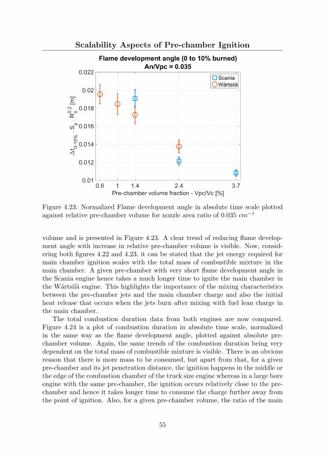
Scalability Aspects of Pre-chamber Ignition
Figure 4.23: Normalized Flame development angle in absolute time scale plottedagainst relative pre-chamber volume for nozzle area ratio of 0.035 cm−1
volume and is presented in Figure 4.23. A clear trend of reducing flame develop-ment angle with increase in relative pre-chamber volume is visible. Now, consid-ering both figures 4.22 and 4.23, it can be stated that the jet energy required formain chamber ignition scales with the total mass of combustible mixture in themain chamber. A given pre-chamber with very short flame development angle inthe Scania engine hence takes a much longer time to ignite the main chamber inthe Wartsila engine. This highlights the importance of the mixing characteristicsbetween the pre-chamber jets and the main chamber charge and also the initialheat release that occurs when the jets burn after mixing with fuel lean charge inthe main chamber.
The total combustion duration data from both engines are now compared.Figure 4.24 is a plot of combustion duration in absolute time scale, normalizedin the same way as the flame development angle, plotted against absolute pre-chamber volume. Again, the same trends of the combustion duration being verydependent on the total mass of combustible mixture is visible. There is an obviousreason that there is more mass to be consumed, but apart from that, for a givenpre-chamber and its jet penetration distance, the ignition happens in the middle orthe edge of the combustion chamber of the truck size engine whereas in a large boreengine with the same pre-chamber, the ignition occurs relatively close to the pre-chamber and hence it takes longer time to consume the charge further away fromthe point of ignition. Also, for a given pre-chamber volume, the ratio of the main
55

Scalability Aspects of Pre-chamber Ignition
chamber volume engulfed by the pre-chamber jets to the combustion chambervolume reduces with an increase in the combustion chamber volume and hencethe portion of main chamber charge consumed by conventional flame propagationincreases.
Figure 4.24: Normalized Combustion duration in absolute time scale plottedagainst absolute pre-chamber volume for nozzle area ratio of 0.035 cm−1
The same data replotted against relative pre-chamber volume, as shown inFigure 4.25, shows a clear trend and also confirms the scaling effects previouslydiscussed. It is interesting to note that unlike the flame development angle (Fig-ure 4.23), the dependency of combustion duration on relative pre-chamber volumeseems to be non-linear as the trends appear to flatten out beyond the relative vol-ume of 2.4%. This can partially be explained by the previously discussed trends(section 4.3) of the flame development angle being relatively less affected by chang-ing the pre-chamber volume from 2.4 to 3.7%, since the main combustion ignitesbefore the combustion inside the pre-chamber ends. It can therefore be stated thatpre-chambers with a relative volume greater than 2.4% do not reduce the flamedevelopment angle and combustion duration greatly but contribute to unburnthydrocarbon emissions due to incomplete combustion inside the pre-chamber.
All other analysis is presented in Paper VI, but from the results it is clear thatthe performance of a pre-chamber of a given volume and nozzle diameter doesdepend, to a great extent, on the displacement volume of the main chamber.
56

Scalability Aspects of Pre-chamber Ignition
Figure 4.25: Normalized Combustion duration in absolute time scale plottedagainst relative pre-chamber volume for nozzle area ratio of 0.035 cm−1
57
Chapter 5
CFD Simulations ofPre-chamber Jets’ mixingcharacteristics
Experimental data suggests that increasing the volume of a pre-chamber providesbetter ignition, seen in terms of shorter flame development angle and combustionduration, but, with higher engine-out NOx emissions. At a given pre-chamber vol-ume, the smallest nozzle diameter (nozzle diameter ratio of 0.025 cm−1) providesthe best ignition performance. The observed trends of pre-chamber combustionand the resulting pressure build-up between the chambers were difficult to explainsolely from the experimental data. It was therefore necessary to further scrutinizethe data to understand the effect of the pre-chamber volume and nozzle diameteron the main chamber ignition.
The ignition from a pre-chamber system is a complex phenomenon governedby the chemical kinetic and fluid dynamic aspects of interaction between the pre-chamber jets and the main chamber charge. It is important to understand boththese aspects to fully understand the behavior of a pre-chamber; but since detailednumerical simulations of combustion in an engine with pre-chamber was outsidethe scope of this reseach, relatively simpler CFD simulations were conducted tounderstand the fluid dynamic aspects alone. This investigation is carried out byperforming 3D, transient, RANS type simulation on a 45◦ sector mesh of thecombustion chamber with the experimentally measured pre- and main chamberpressure data as boundary conditions.
As discussed earlier with Figure 4.15, pre-chamber volume has a stronger effecton the flame development angle than the nozzle diameter. Whereas for combustionduration as seen in Figure 4.16, the nozzle diameter has a stronger effect than thepre-chamber volume. Following hypotheses were developed based on these resultswhich are evaluated by CFD simulations:
58
CFD Simulation Setup
• Jets from a larger pre-chamber have higher momentum which results inhigher penetration speed and hence greater depth of penetration
• Higher momentum jets also generate turbulence early on in the main chamberwhich promotes mixing between the pre-chamber jets and the main chambercharge.
• For a given pre-chamber volume, a smaller nozzle diameter causes highervelocity jets which promotes mixing between the pre-chamber jets and themain chamber charge
5.1 CFD Simulation Setup
The CFD simulations presented in this article were performed using ANSYS R©
Fluent R©, Release 15.0, and were of RANS type using the realizable k-ε turbulencemodel which can more accurately predicts the spreading rate of round jets [58],as are expected in the present case. A density based numerical solver with im-plicit formulation was used with second order upwind spatial discretization schemefor flow, turbulence and transient formulation. Species transport model, with apre-existing mixture template of Methane-Air, was used to simulate the mixingbetween pre-chamber jets and main chamber charge. The time duration startingfrom spark discharge and equal to the flame development angle was simulated foreach operating point in the Scania engine experimental matrix (table 4.1). Exper-imentally measured pre-chamber pressure was used as the boundary condition atthe pre-chamber nozzle inlet. Further details of the computation grid, initial andboundary conditions can be found in Paper V.
5.2 Results and Discussions
This section presents the results obtained after simulation of all 9 cases. Data onproperties of interest (species concentration etc.) were exported from the CFDsoftware after every time step and were post processed using MATLAB wherecomparisons between all 9 cases were made. Selected results are discussed in thissection. The legends (e.g. A3) in the plots correspond to a particular combinationof pre-chamber volume and nozzle diameter as per table 4.1.
Depth of Penetration
Jet penetration behavior was determined by compiling data on methane concen-tration along the jet axis for each time setup for a given case. The resulting jetpenetration behavior for all 9 cases is plotted in Figure 5.1.
It should be noted that the x-axis is the time after spark ignition in the pre-chamber, so the differences in the start of pre-chamber ejection are also includedin the plot. As can be seen, the jet penetration curve flattens out after some time
59

Results and Discussions
which is either because the jet has reached the combustion chamber wall or hasdisintegrated before reaching the wall and does not travel any further. The endof the curve represents the end of the flame development angle in the respectivecase, i.e. the time of ignition and start of combustion in the main chamber.
It is apparent from the figure that there is a significant difference in startof ejection for case B, whereas the ejections for cases A and C start almost atthe same time. This suggests that there are differences in the flow field insidethe pre-chamber which affect the start of ejection. For case B, it can be seenthat smaller nozzle diameter causes earlier ejection, which could be due to bettermixing inside the pre-chamber during the flow of fresh charge from the main tothe pre-chamber during the compression stroke. Whereas, the air-fuel mixtureinside the pre-chamber in the largest nozzle diameter case is comparatively morestratified and hence combustion proceeds with a slower rate after spark ignition.Such differences are also expected in case A and C, but are perhaps not prominentat the current settings of volume and nozzle diameter for those cases.
Figure 5.1: Depth of penetration of PC ejections for various volume and nozzlediameter cases.
It is also interesting to note the apparent change in the slope of jet penetrationcurves for the smallest volume case A. This suggests that for the time before thechange in slope, jet head motion is governed by the momentum provided by thejet but further on, the jet loses its momentum and slows down as it penetratesfurther in the main chamber, which finally affects the depth of penetration.
In terms of depth of penetration, it can be seen that jets from the largestpre-chamber (C1 – C3) reach the combustion chamber wall for all the nozzlediameters, which is in line with the arguments of jet momentum presented earlier.For volume case B, jets for the smallest and intermediate nozzle diameter cases
60

Results and Discussions
reach the combustion chamber wall whereas the largest nozzle diameter case (B3)disintegrates half way. And finally for volume case A, only the jets for the smallestnozzle diameter case reach the combustion chamber wall. From these trends it canbe deduced that nozzle diameter has a prominent effect on the depth of penetrationand hence the distribution of active species in the main chamber. Jet penetrationto the wall is beneficial because the recirculation zones created will enhance mixingin the main chamber, however, jet-wall interaction also increases heat transfer.
Figure 5.2 is a plot of average jet penetration velocity, calculated from thedistance traveled by the jet during the time span between the start of ejection untilthe jet reaches the combustion chamber wall or stops traveling further. It can beseen that the rate of penetration is mainly affected by and is proportional to thepre-chamber volume. This is due to the differences in the absolute mass and hencethe momentum of pre-chamber ejections, which increases with an increase in thepre-chamber volume. It should also be noted that since the nozzle diameter ratiois maintained constant, with an increase in pre-chamber volume, the absolute sizeof the nozzles increases and hence the jet core is thicker for a larger pre-chamber.It is hence capable of penetrating faster through the main chamber before the corebreaks down. Regarding the effect of nozzle diameter, it can be seen that a jetfrom smaller nozzle diameter penetrates faster through the combustion chamberwhich is solely due to higher velocity and hence higher momentum for the jet.
Figure 5.2: Depth of penetration of PC ejections for various volume and nozzlediameter cases.
Jet Development and Structure
It has previously (section 4.3) been hypothesized that in absence of sufficientpressure difference built-up between the chambers, or for a jet from small nozzle
61
Results and Discussions
diameter which is expected to have lower momentum; the pre-chamber ejectionswill not lead to jet development, but form a ’mushroom cloud’ instead. To testthis hypothesis, the relation between the instantaneous jet exit velocity at thenozzle (VBase) and the instantaneous jet head velocity (VHead) are compared. Thehypothesis is tested by studying the differences in how well the jet head velocityfollows the jet exit velocity, since in case of a mushroom cloud, the jet head velocitywill drop faster and even to 0 in-spite of having a significantly high jet exit velocity.The jet exit velocity is obtained from the simulations by taking an average ofvelocity magnitudes for the nodes on the Jet Axis line which are within the nozzlelength. The instantaneous jet head velocity is calculated by differentiating thecurves in figure 5.1.
Figure 5.3 is a plot of the ratio of jet head velocity to jet exit velocity. Pleasenote that unlike figure 5.1, the X-axis in this figure is time after the start of pre-chamber ejection, hence the curves are shifted in time to exclude the effect ofdifference in the start of ejection and to enable fair comparison between the jetsalone. It can be seen from the figure that after almost 0.5 ms following start ofejections, the jet head velocity drops below 20% of the jet exit velocity in all thecases. This indicates that the differences in jet head velocity are not as distinct asexpected and hence the structure of ejection is essentially the same without anyindication of formation of distinct mushroom clouds in any cases. Never the less,the differences of interest are the rate at which this ratio falls from the beginningof ejection. The smallest nozzle diameter cases (A1, B1 and C1) are the first onesto slow down. The second set of curves are the intermediate nozzle diameter cases(A2, B2 and C2) and then the third set of curves for largest nozzle diameter cases(A3, B3 and C3) which slow down the latest. Even at a later time of 0.42 ms,it can be seen that the jet head velocity for the largest nozzle diameter cases isabout 20-25% of jet exit velocity whereas for the smallest nozzle diameter case, thejet head velocity is below 10% of the jet exit velocity, suggesting a comparativelymushroom cloud like structure of ejection. Considering that these plots of jethead velocity are normalized over their respective nozzle exit velocity and henceare isolated from the effects of absolute mass ejected, it can be stated that nozzlediameter has a clear effect on the structure of the jet.
The structure of the jet will have a direct effect on the distribution of thepre-chamber jet contents in the main chamber. A jet like structure travels furtherin the combustion chamber and hence provides better spatial distribution of pre-chamber jet contents, whereas a mushroom cloud will deposit the pre-chambercontents closer to the pre-chamber and also limit the mixing between the ejectedcontents and main chamber given the lower jet head velocity. This, in effect, willprolong the combustion duration since a larger portion of the main chamber chargeis consumed by conventional flame propagation. This is in conformity with theprevious results obtained from engine experiments, as presented in Figure 4.16.
62

Results and Discussions
Figure 5.3: A ratio of jet head to the jet exit velocity for various volume and nozzlediameter cases.
Main Chamber Turbulence
Data on turbulence in the computational domain was also analyzed to understandthe rate of production of turbulent kinetic energy in the main chamber due to thepre-chamber jets. It was found that for a given pre-chamber volume, a smallernozzle diameter causes high velocity jets and hence higher turbulence generationin the main chamber, which will accelerate mixing in the main chamber. Also, itwas found that the average turbulence level in the main chamber increases withan increase in the pre-chamber volume, which confirms the previously discussedhypothesis that jets from a larger pre-chamber engulf greater volume of mainchamber charge. This effect can be related to the increase in engine out NOx andshorter combustion duration. These results are presented in detail in Paper V.
The results of CFD simulations confirm some of the previously developed hy-potheses, and also help explain the experimental results better. It should howeverbe noted that these simulations only took into account the fluid dynamic aspectsof the mixing characteristics in the main chamber while excluding the equallyimportant chemical kinetic effects. An example of the implications is incorrectprediction of depth of penetration, since the head of the jet may react with themain chamber charge before the flame development angle duration has ended. Thismeans that the predicted depth of penetration is longer than the actual depth ofpenetration and hence the jet penetration velocity and all other related data iserroneous. These results should therefore be used with caution.
63

Chapter 6
Summary and Conclusions
A series of studies were conducted to evaluate a pre-chamber ignition system asan alternative to a conventional open-chamber spark ignition system, as a meansto improve fuel efficiency and reduce harmful emissions of internal combustionengines operating with gaseous fuels.
Both types of a pre-chamber ignition systems, with and without additionalfueling to the pre-chamber, were studied. From the experiments comparing theperformance of un-fueled pre-chamber spark plugs to that of conventional sparkplugs on a multi-cylinder engine, it was found that using the pre-chamber sparkplugs leads to a much shorter flame development angle and better combustion sta-bility, but with minor extension in the engine’s dilution limit which also restrictsthe improvement in fuel efficiency. Pre-chamber spark plugs were also found tocause pre-ignition beyond a threshold operating load, in effect reducing the maxi-mum operating load of the engine. The reduction in emissions, specifically NOx,was also minor.
Studies conducted with fueled pre-chamber ignition systems operating with afuel-rich pre-chamber combustion strategy showed considerable extension of thedilution limit with excess air in the main chamber, with stable combustion atexcess air ratios (λ) of up to 2.6. As a result, gross indicated efficiency of over47% and engine out NOx emissions below 1 g/kW.h were achieved. Followingstudies on the effect of the pre-chamber volume and nozzle diameter showed thatincreasing the relative pre-chamber volume up to 2.4% considerably improves mainchamber ignition behavior without significantly increasing NOx emission, whereasa further increase in the pre-chamber volume only contributes to higher NOx
emissions without any significant improvement in the main chamber ignition. Thesmallest nozzle diameter ratio of 0.025 cm−1 was found to provide best mainchamber ignition but a larger nozzle diameter extends the dilution limit of mainchamber combustion.
The dependency of these optimal settings on the engine’s displacement volume,that is, the scaling requirements when applying pre-chamber ignition systems to
64

engines of various sizes were then studied by conducting experiments also on alarge bore marine engine. It was found that the behavior of a pre-chamber ofa given geometry and mixture strength is greatly affected by the properties ofthe main combustion chamber. The results showed that the pre-chamber volumeneeds to be scaled with the engine’s displacement volume. Experiments on thelarge bore engine also demonstrated gross indicated efficiencies of over 50% atsome operating points.
From these results, it can be established that a pre-chamber ignition systemoperating with a fuel rich pre-chamber combustion strategy is a very effectivealternative to the conventional open chamber spark ignition system typically usedin heavy duty engines running on gaseous fuels today. The pre-chamber ignitionsystem has great potential in improving fuel efficiency and reducing engine-outNOx emissions, hence addressing both global and local emission challenges.
Some key conclusions regarding the characteristics of pre-chamber ignition sys-tem that can be drawn from these studies are listed below.
• Isolating the spark gap from the main chamber charge motion by using apre-chamber considerably reduces cycle to cycle variation in the ignition andmain chamber combustion events.
• Un-fueled pre-chamber ignition systems, like a pre-chamber spark plug, areunable to extend the dilution limit of the engine due to over-leaning of thecharge inside the pre-chamber.
• A pre-chamber ignition system without an effective heat removal mechanismmay act as a hot spot in the main combustion chamber causing pre-ignitionand hence unstable combustion.
• Additional fueling to the pre-chamber scavenges the pre-chamber at the be-ginning of every cycle and also forms a readily ignitable mixture in a verysmall volume around the spark gap, while the comparatively larger mainchamber operates with an extremely fuel-lean charge. This configurationcan results in very high indicated efficiency and reduce NOx emissions.
• A relative pre-chamber volume of 2.4% is an optimal trade-off between mainchamber ignition characteristics and engine out NOx emissions.
• The nozzle diameter setting is case specific, depending on the relative im-portance of main chamber ignition characteristics and the dilution limit ofthe main chamber combustion.
65

Chapter 7
Suggestions for futureactivities
Even though the capabilities of pre-chamber ignition systems have been establishedand the optimal settings for the pre-chamber volume and nozzle diameter havebeen found, there is a need to further understand the fundamental mechanismsof the processes involved in pre-chamber ignition. There is a potential for furtherimprovement and optimization and therefore, some research areas which the authorbelieves should be further explored are listed below.
• Mixture formation inside the Pre-chamber: For the purpose of calcu-lating the pre-chamber excess air ratio (λpc) in the studies presented in thisthesis, the mixture inside the pre-chamber was assumed to be homogeneous.It is already known [59, 60] that the mixture inside the pre-chamber is strati-fied with most of the fuel in the top region of the pre-chamber and a fuel-leanmain chamber charge at the bottom, with a mixing zone in between. Sincefresh charge is continuously pushed into the pre-chamber during the com-pression stroke, it will be very difficult to achieve a homogeneous mixture ofair and fuel inside the pre-chamber at the time of spark; but care should betaken to limit the charge stratification only along the axial direction. Radialcharge stratification at any height inside the pre-chamber with isolated fuel-rich zone should be avoided. It is therefore very important to understandhow the geometry of the pre-chamber and other operating parameters of theengine, like the engine speed and compression ratio, affect mixture formationinside the pre-chamber. CFD simulations are best suited for such studies,but even experimental studies with an in-pre-chamber sampling valve can beperformed to understand pre-chamber mixture formation.
66

• The relationship between the Pre-chamber Volume and Nozzle Di-ameter and the Combustion Inside the Pre-chamber: The combus-tion inside the pre-chamber is one of the most important aspects whichdirectly affects the contents of the pre-chamber jets. The main factors con-trolling pre-chamber combustion are the quantity of fuel, the volume of thepre-chamber, the surface to area ratio of the pre-chamber cavity and the noz-zle diameter. Since the pre-chamber is thermodynamically an open system,there is a flow of mass from pre- to main chamber when combustion insidethe pre-chamber starts. The fact that a measurable pressure difference existsbetween the chambers suggests that the rate of energy release inside the pre-chamber due to combustion is higher than the rate of energy loss due to massflow out of the pre-chamber. Therefore for a given pre-chamber volume, thenozzle diameter plays the key role in controlling the extent of each of theseprocesses and hence the contents of the pre-chamber jets. Insufficient nozzlediameter will impose very high flow restriction across the chambers result-ing in high pressure and temperature buildup inside the pre-chamber. Thisin-turn promotes combustion inside the pre-chamber. On the other hand,excessive nozzle diameter will release the pressure very rapidly and hence thecombustion inside the pre-chamber may quench, resulting in un-burnt fuelin the pre-chamber jets. And as can already be appreciated, this behavioris greatly affected by the chemical kinetic properties of the fuel being usedand hence studies conducted with a particular fuel are difficult to generalize.This phenomenon should therefore be studied by modeling the combustioninside the pre-chamber for various pre-chamber volume and nozzle diametercases. Figures like 7.1 and 7.2 can be expected out of the proposed modelingactivity. Figure 7.1 shows the flow of various species for the duration of pos-itive ∆P between the chambers. Due to the axial charge stratification, thecontents that first flow out of the pre-chamber is the main chamber mixture(MC mixture) and as time progresses, the flow of partial combustion prod-ucts (Formaldehyde and CO) starts to emerge out of the pre-chamber. Thisprocess will be affected by the geometry of the pre-chamber and the surfaceto area ratio which governs heat transfer.
A similar modeling study of the effect of nozzle diameter for a given pre-chamber volume may result in figure 7.2 which shows the total mass of a givenspecies that flows out of the pre-chamber during one ignition event. The plotsuggests that with insufficient nozzle diameter, the combustion inside the pre-chamber is relatively complete and hence the total mass of partial combustionproducts is high, but for a larger nozzle diameter, the combustion insidethe pre-chamber stalls and hence the mass of partial combustion productsreduces while the mass of main chamber charge being pushed back into themain chamber as the pressure rises, increases.
67
Figure 7.1: Hypothesized model output for species flow rate from the pre-chamber
Figure 7.2: Hypothesized model output for the effect of nozzle diameter
68

• Main Chamber Ignition: The interaction of the pre-chamber jets andmain chamber charge is least understood. The best approach is opticaldiagnostics using active laser diagnostic techniques like Laser Induced Flu-orescence (LIF) to understand the effect of fuel rich combustion in the pre-chamber (and also the inhomogeneity of the mixture inside the pre-chamber)on the concentration of active species ejected in the main chamber, and theireffect on the main chamber ignition. Ignition by transient jets are importantin several other applications like explosion protection [61] and perhaps thefundamental mechanism of ignition by pre-chamber jets bears some resem-blance.
69

Bibliography
[1] IPCC, 2014: Climate Change 2014: Synthesis Report. Contribution of Work-ing Groups I, II and III to the Fifth Assessment Report of the Intergovern-mental Panel on Climate Change [Core Writing Team, R.K. Pachauri andL.A. Meyer (eds.)]. IPCC, Geneva, Switzerland, 151 pp.
[2] Annual European Union greenhouse gas inventory 1990-2011 and inventoryreport 2013, Technical report No. 8/2013, European Environment Agency,2013.
[3] ’Inventory of U.S. Greenhouse Gas Emissions and Sinks: 1990-2013’, The U.S.Environmental Protection Agency Report No. EPA 430-R-15-004, 2015.
[4] ’How nitrogen oxides affect the way we live and breathe’, The U.S. Environ-mental Protection Agency Report No. EPA 456/F-98-005, 1998.
[5] P. Wolkoff, C. K. Wilkins, P. A. Clausen, and G. D. Nielsen. Organic com-pounds in office environments sensory irritation, odor, measurements and therole of reactive chemistry. Indoor Air, 16(1):7–19, 2006.
[6] Stanley T. Omaye. Metabolic modulation of carbon monoxide toxicity. Tox-icology, 180(2):139 – 150, 2002.
[7] P. Tikuisis, D. M. Kane, T. M. McLellan, F. Buick, and S. M. Fairburn. Rateof formation of carboxyhemoglobin in exercising humans exposed to carbonmonoxide. Journal of Applied Physiology, 72(4):1311–1319, 1992.
[8] Ole et al. Raaschou-Nielsen. Air pollution and lung cancer incidence in 17european cohorts: prospective analyses from the european study of cohortsfor air pollution effects (escape). The Lancet Oncology, 14(9):813–822, 2013.
[9] IARC: diesel engine exhaust carcinogenic, International Agency for Researchon Cancer, Press Release No. 213, 12th June, 2012.
[10] Clean Power for Transport: A European alternative fuels strategy, EuropeanCommission com (2013) 17, 24/1/2013.
70

BIBLIOGRAPHY
[11] Data cource: US Energy Information Administration (2013).
[12] ’Well-to-wheels analysis of future automotive fuels and powertrains in theEuropean context’, European Commission Joint Research Centre, Institutefor Energy, WELL-to-WHEELS Report Version 3c, July 2011.
[13] J.D. Dale, M.D. Checkel, and P.R. Smy. Application of high energy ignitionsystems to engines. Progress in Energy and Combustion Science, 23(56):379– 398, 1997.
[14] Smy P. Dale, J. and R. Clements. Laser ignited internal combustionengine - an experimental study. SAE Technical Paper 780329, 1978.doi:10.4271/780329.
[15] Richardson S. Woodruff S. McMillian, M. and D. McIntyre. Laser-spark ig-nition testing in a natural gas-fueled single-cylinder engine. SAE TechnicalPaper 2004-01-0980, 2004. doi:10.4271/2004-01-0980.
[16] Karim GA. combustion in Gas Fueled Compression: Ignition Engines of theDual Fuel Type. ASME. J. Eng. Gas Turbines Power. 2003;125(3):827-836.doi:10.1115/1.1581894.
[17] Ghazi A. Karim. A review of combustion processes in the dual fuel enginethegas diesel engine. Progress in Energy and Combustion Science, 6(3):277 –285, 1980.
[18] Schock H. Toulson, E. and W. Attard. A review of pre-chamber initiatedjet ignition combustion systems. SAE Technical Paper 2010-01-2263, 2010.doi:10.4271/2010-01-2263.
[19] ’Volvo Trucks declares itself first manufacturer of efficient Dual-fuel Euro VEngine, NGV Global news December 15, 2009.
[20] Information on Gas fired engines from company website,http://www.wartsila.com, retrieved on 25/10/2013.
[21] Information on Gas fired engines from company website,http://www.man.com, retrieved on 25/10/2013.
[22] Lyle Cummins. Internal Fire: The Internal Combustion Engine 1673-1900.Carnot Press, 2002.
[23] N. A. Otto. Improvement in gas-motor engines. US Patent 194,047, 1877.
[24] Harry Ralph Ricardo. Internal-combusiton engine. US Patent 1,271,942, 1918.
[25] Caleb E. Summers. Internal-combusiton engine. US Patent 1,568,638, 1926.
[26] Marion Mallory. Internal-combusiton engine. US Patent 2,121,920, 1937.
71
BIBLIOGRAPHY
[27] Albert Bagnulo. Internal combusiton engine fed with heavy fuels. US Patent2,065,419, 1933.
[28] Albert Bagnulo. Engine with stratified mixture. US Patent 2,422,610, 1938.
[29] Neil O. Broderson. Method of operating internal-combustion engines. USPatent 2,615,437, 1952.
[30] Ralph M. Heintz. Internal combustion engine. US Patent 2,884,913, 1959.
[31] Goossak Lev Abramovich. Method of prechamber-torch ignition in internalcombustion engines. US Patent 3,230,939, 1966.
[32] Gussak, L., Turkish, M., and Siegla D. High chemical activity of incompletecombustion products and a method of prechamber torch ignition for avalancheactivation of combustion in internal combustion engines. SAE Technical Paper750890, 1975. doi:10.4271/750890.
[33] Gussak L. The role of chemical activity and turbulence intensity inprechamber-torch organization of combustion of a stationary flow of a fuel-airmixture. SAE Technical Paper 830592, 1983. doi:10.4271/830592.
[34] Henry K. Newhall and Ibrabim A. El-Messiri. A combustion chamber conceptfor control of engine exhaust air pollutant emissions. Combustion and Flame,14(1):155 – 158, 1970.
[35] T. Ken Garrett. Porsche stratified charge engine. Environmental Science &Technology, 9(9):826–830, 1975.
[36] W.R. Brandstetter and G. Decker. Fundamental studies on the volkswagenstratified charge combustion process. Combustion and Flame, 25:15 – 23,1975.
[37] Goossak Lev Abramovich. Pulsed jet combustion generator for premixedcharge engines. US Patent 4,926,818, 1989.
[38] J.A. Maxson and A.K. Oppenheim. Pulsed jet combustionkey to a refinementof the stratified charge concept. Symposium (International) on Combustion,23(1):1041 – 1046, 1991. Twenty-Third Symposium (International) on Com-bustion.
[39] Eiichi Murase, Shinsuke Ono, Kunihiko Hanada, Jyong Ho Yun, and An-toni K. Oppenheim. Performance of pulsed combustion jet at high pressuresand temperatures. {JSAE} Review, 17(3):245 – 250, 1996.
[40] Wolanski, P., Dabkowski, A., and Przastek J. Influence of pjc ignition onefficiency and emission of ic piston engine operating at partial and full load.SAE Technical Paper 972871, 1997. doi:10.4271/972871.
72
BIBLIOGRAPHY
[41] David L. Reuss Paul M. Najt, Rodney Brewer Rask. Dual mode enginecombustion process. US Patent 6,595,181, 2003.
[42] David Cook Jasim Ahmed Aleksandar Kojic, Jean-Pierre Hathout. Controlof auto-ignition timing for combustion in piston engines by prechamber com-pression ignition. US Patent 6,953,020, 2005.
[43] Pape-J. Gruenig C. Kuhnert D. Getzlaff, J. Investigations on pre-chamberspark plug with pilot injection. SAE Technical Paper 2007-01-0479, 2007.doi:10.4271/2007-01-0479.
[44] William Attard. Turbulent jet ignition pre-chamber combustion system forspark ignition engines. US Patent 2012/0103302, 2012.
[45] Kohn-J. Attard, W. and P. Parsons. Ignition energy development for a sparkinitiated combustion system capable of high load, high efficiency and near zeronox emissions. SAE Int. J. Engines 3(2):481-496, 2010. doi:10.4271/2010-32-0088.
[46] Fraser-N. Parsons P. Attard, W. and E. Toulson. A turbulent jet ignition pre-chamber combustion system for large fuel economy improvements in a modernvehicle powertrain. SAE Int. J. Engines 3(2):20-37, 2010. doi:10.4271/2010-01-1457.
[47] P. Einewall and B. Johansson. Combustion chambers for supercharged naturalgas engines. SAE Technical Paper 970221, 1997. doi:10.4271/970221.
[48] Toulson, E., Schock, H., and Attard W. A Review of Pre-Chamber InitiatedJet Ignition Combustion Systems. SAE Technical Paper 2010-01-2263, 2010.doi:10.4271/2010-01-2263.
[49] Gussak, L., Karpov, V., and Tikhonov Y. The application of lag-process inprechamber engines. SAE Technical Paper 790692, 1979. doi:10.4271/790692.
[50] John B Heywood. Internal combustion engine fundamentals. Mcgraw-hillNew York, 1988.
[51] G. Woschni. A universally applicable equation for the instantaneous heattransfer coefficient in the internal combustion engine. SAE Technical Paper670931, 1967. doi:10.4271/670931.
[52] Nielsen-L. Eriksson, L. and J. Nytomt. Ignition control by ionization currentinterpretation. SAE Technical Paper 960045, 1996. doi:10.4271/960045.
[53] Y. Cao and L. Li. A novel closed loop control based on ionization current incombustion cycle at cold start in a gdi engine. SAE Technical Paper 2012-01-1339, 2012. doi:10.4271/2012-01-1339.
73

BIBLIOGRAPHY
[54] G. Malaczynski and M. Baker. Real-time digital signal processing of ionizationcurrent for engine diagnostic and control. SAE Technical Paper 2003-01-1119,2003. doi:10.4271/2003-01-1119.
[55] Roethlisberger, R., and Favrat D. Investigation of the prechamber geometricalconfiguration of a natural gas spark ignition engine for cogeneration: part i.numerical simulation. International Journal of Thermal Sciences, 42(3):223–237, 2003. doi:10.1016/S1290-0729(02)00023-6.
[56] Yagi-S. Ishizuya A. Date, T. and I. Fujii. Research and development of thehonda cvcc engine. SAE Technical Paper 740605, 2003. doi:10.4271/740605.
[57] ENGVA position paper on Euro-VI emission limits in relation to heavy-dutynatural gas vehicles. European Natural Gas Vehicle Association, Updatedversion, 2007.
[58] ANSYS R© Fluent R©, Release 15.0, Theory Guide, 4.3.3. Realizable k-ε Model,ANSYS, Inc.
[59] Gi-Heon Kim Allan Kirkpatrick and Daniel Olsen. Cfd modeling of the per-formance of a prechamber for use in a large bore natural gas engine. PaperNo. ICES2005-1049 in the Proceedings of ICES2005 - ASME Internal Com-bustion Engine Division 2005 Spring Technical Conference, April 5-7, 2005,Chicago, IL, USA, 2014.
[60] D Favrat S Heyne, G Millot. Numerical simulations of a prechamber autoigni-tion engine operating on natural gas. International Journal of Thermodynam-ics (IJoT), 14(2):43–50, 2011. doi:10.5541/ijot.166.
[61] A. Ghorbani, G. Steinhilber, D. Markus, and U. Maas. Ignition by transienthot turbulent jets: An investigation of ignition mechanisms by means of apdf/redim method. Proceedings of the Combustion Institute, 35(2):2191 –2198, 2015.
74