
Improving pH Probe Measurement Accuracy for an...
25
ECE 492 Design Document Improving pH Probe Measurement Accuracy for an Automatic Marine Alkalinity Measurement Device Faculty Advisor: Dr. Kenneth J. Hintz Faculty Member: Dr. Nathalia Peixoto Team Members: Ambar Rathie Erick Chacon Akash Malhotra May 02, 2014
Transcript of Improving pH Probe Measurement Accuracy for an...

ECE 492
Design Document
Improving pH Probe Measurement Accuracy
for an Automatic Marine Alkalinity
Measurement Device
Faculty Advisor: Dr. Kenneth J. Hintz
Faculty Member: Dr. Nathalia Peixoto
Team Members:
Ambar Rathie
Erick Chacon
Akash Malhotra
May 02, 2014

May 2, 2014 Automatic Marine Alkalinity Measurement Device Improvement Version 3
Page 2 of 25
Problem Statement
The purpose of this project is to improve upon a device that automatically measures pH
in order to calculate the alkalinity of seawater using the patented method of reverse gran titration
[6] by Dr. Kenneth Hintz and Dr. Christopher Hintz. The current device (Figure 1), designed and
implemented by Dr. K. Hintz, obtains an inaccurate reading from the pH electrodes. The task of
improvement consists of obtaining an accurate reading of pH with a ±0.02 error margin. The
final stage of our project will be incorporated into the current device prototype as shown in
figure 1.
Introduction
Alkalinity is a measurement of the ability of a solution to neutralize acids. Alkalinity of
water is due primarily to the presence of bicarbonate, carbonate, and hydroxide ions. Alkalinity
is significant in the treatment process of water. Furthermore, if any changes are made to water
that could raise or lower the pH value, alkalinity acts as a buffer, protecting the water and its life
forms from sudden shifts in pH. Alkalinity should not be confused with pH. The pH of a
solution is a measure of the concentration of acid, or H+ ions, in that solution. The mathematical
formula is defined as follows:
𝑝𝐻 = −log(𝐻+)
Figure 1: Current Alkalinity measurement device prototype
May 2, 2014 Automatic Marine Alkalinity Measurement Device Improvement Version 3
Page 3 of 25
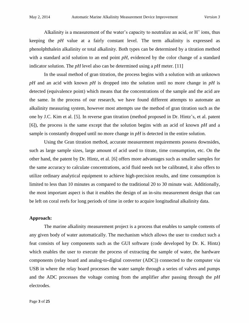
Alkalinity is a measurement of the water’s capacity to neutralize an acid, or H+ ions, thus
keeping the pH value at a fairly constant level. The term alkalinity is expressed as
phenolphthalein alkalinity or total alkalinity. Both types can be determined by a titration method
with a standard acid solution to an end point pH, evidenced by the color change of a standard
indicator solution. The pH level also can be determined using a pH meter. [11]
In the usual method of gran titration, the process begins with a solution with an unknown
pH and an acid with known pH is dropped into the solution until no more change in pH is
detected (equivalence point) which means that the concentrations of the sample and the acid are
the same. In the process of our research, we have found different attempts to automate an
alkalinity measuring system, however most attempts use the method of gran titration such as the
one by J.C. Kim et al. [5]. In reverse gran titration (method proposed in Dr. Hintz’s, et al. patent
[6]), the process is the same except that the solution begins with an acid of known pH and a
sample is constantly dropped until no more change in pH is detected in the entire solution.
Using the Gran titration method, accurate measurement requirements possess downsides,
such as large sample sizes, large amount of acid used to titrate, time consumption, etc. On the
other hand, the patent by Dr. Hintz, et al. [6] offers more advantages such as smaller samples for
the same accuracy to calculate concentrations, acid fluid needs not be calibrated, it also offers to
utilize ordinary analytical equipment to achieve high-precision results, and time consumption is
limited to less than 10 minutes as compared to the traditional 20 to 30 minute wait. Additionally,
the most important aspect is that it enables the design of an in-situ measurement design that can
be left on coral reefs for long periods of time in order to acquire longitudinal alkalinity data.
Approach:
The marine alkalinity measurement project is a process that enables to sample contents of
any given body of water automatically. The mechanism which allows the user to conduct such a
feat consists of key components such as the GUI software (code developed by Dr. K. Hintz)
which enables the user to execute the process of extracting the sample of water, the hardware
components (relay board and analog-to-digital converter (ADC)) connected to the computer via
USB in where the relay board processes the water sample through a series of valves and pumps
and the ADC processes the voltage coming from the amplifier after passing through the pH
electrodes.

May 2, 2014 Automatic Marine Alkalinity Measurement Device Improvement Version 3
Page 4 of 25
In the existing prototype, the GUI software controls the microcontroller USB ERB08,
which is what controls the solenoid valves and pumps in the relay board. It will have capabilities
such as closing or opening specific valves, operating the pumps, determining the exact amount of
salt water extracted (at least 50 milliliters), the amount of acid injected, and obviously executing
the process. Once the software execution on the mechanism is complete, the user no longer has
control over the process itself, unless stopped manually.
Since we already know the problem at hand (namely, a wrong pH measurement after reading,
amplifying the voltage produced by the pH electrodes, and computing the actual pH value) we
will identify the main source of the issue. All mechanical components (Figure 1) have been
tested for proper behavior and the ones that did not succeed were the pH electrodes along with
the precision instrumentation amplifier. Individually, each carries their own function. That is, the
pH electrodes produce a voltage based on the fluids flowing through them and the amplifier
amplifies the voltage at a predetermined gain in order to make the dynamic range of the pH
measurements match the dynamic range of the input to the ADC. However, when operated
collectively, the pH measurement from a solution with a known pH value does not yield the
correct result.
Requirements Specification
In this project, we must replace or improve upon components of previous prototype to
ensure an accurate pH reading from electrode to 2 decimal places (e.g., 8.32 ± 0.02). Errors of
measurement must be minimized and analyzed in an oscilloscope for a more qualitative result. If
the task is successfully completed prior to the end of senior design, we will assist in the
implementation of a mixing chamber for proper intermingling of acid and seawater. The
components to be reevaluated and/or replaced will be the pH electrodes and the instrumentation
amplifier.
Our project is specifically focused on obtaining a pH reading. Figure 2 shows our black
box design where we have a sample fluid and power as the primary inputs and de-ionized water
as a secondary input to flush out the system. The resulting voltage from the pH measurement will
be read into the A/D converter which in turn, will be read to the GUI.

May 2, 2014 Automatic Marine Alkalinity Measurement Device Improvement Version 3
Page 5 of 25
Figure 2: Our black box design
Figure 3: Our white box design
Figure 4: Our Level 2 design

May 2, 2014 Automatic Marine Alkalinity Measurement Device Improvement Version 3
Page 6 of 25
Background Knowledge
One of the key components in the entire mechanism is the pH probe which has two
electrodes; the reference electrode and the pH electrode (also known as measurement electrode.)
The reference electrode has a specific concentration of hydrogen ions and the pH electrode
obtains the fluid of which the pH is to be measured. As a result, the difference of hydrogen ions
between the reference and pH electrodes generates a voltage that is directly proportional to the
pH value.
In figure 5, we have a more detailed diagram that explains how a pH measurement
electrode operates. The fundamental design of the pH electrode is that the glass body essentially
separates the hydrogen ions from all other ions. The glass is doped with lithium ions and this
makes it electrochemically reactive to hydrogen ions. The glass acts as a strong insulator which
means that if we wish to establish a circuit connection between the measurement and reference
electrode, there is a tremendously high resistance. This high resistance makes it difficult to
measure the voltage across the two electrodes. [1] [11]
Figure 5: Measurement electrode

May 2, 2014 Automatic Marine Alkalinity Measurement Device Improvement Version 3
Page 7 of 25
In figure 6, we have the reference electrode which is made from a neutral pH chemical
buffer solution (usually potassium chloride) allowed to interchange ions with the process
solution through the porous separator, thus forming a relatively low resistance connection to the
test fluid [1.]
Figure 6: Reference electrode
Ideally, the pH electrodes produce a voltage of approximately 59.16 mV per level of pH,
thus demonstrating a linear relationship between voltage and pH. More simply,
𝑉 = (0.05916 ∗ 𝑝𝐻)𝑉𝑜𝑙𝑡𝑠 , where pH = 1 to 14.
Therefore, the range of voltages corresponding to the range of possible pH values is 59.16 mV to
828.24 mV [1]

May 2, 2014 Automatic Marine Alkalinity Measurement Device Improvement Version 3
Page 8 of 25
Figure 7: pH electrodes in Dr. Hintz’s prototype
Voltage Buffer (unity gain buffer) Amplifier
A voltage buffer amplifier is used to transfer a voltage from a first circuit with a
high output impedance level to a second circuit with a low input impedance level. The
interpolated buffer amplifier prevents the second circuit from loading the first circuit
inadmissibly and interfering with its desired operation. In the ideal voltage buffer in the diagram,
the input resistance is infinite, the output resistance zero (impedance of an ideal voltage source is
zero). Other properties of the ideal buffer are: perfect linearity regardless of signal amplitude and
an instant output response regardless of the rise time or bandwidth of the input signal.
If the voltage is transferred unchanged (the voltage gain Av is 1), the amplifier is a unity
gain buffer; also known as a voltage follower because the output voltage follows the input
voltage. Although the voltage gain of a voltage buffer amplifier may be (approximately) unity, it
usually provides considerable current gain. However, it is commonplace to say that it has a gain
of 1 (or the equivalent 0 dB), referring to the voltage gain. [12]
May 2, 2014 Automatic Marine Alkalinity Measurement Device Improvement Version 3
Page 9 of 25
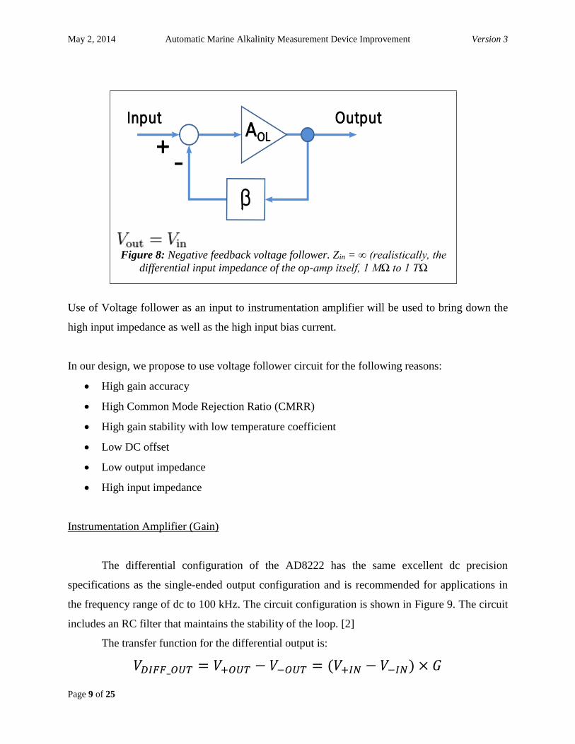
Use of Voltage follower as an input to instrumentation amplifier will be used to bring down the
high input impedance as well as the high input bias current.
In our design, we propose to use voltage follower circuit for the following reasons:
High gain accuracy
High Common Mode Rejection Ratio (CMRR)
High gain stability with low temperature coefficient
Low DC offset
Low output impedance
High input impedance
Instrumentation Amplifier (Gain)
The differential configuration of the AD8222 has the same excellent dc precision
specifications as the single-ended output configuration and is recommended for applications in
the frequency range of dc to 100 kHz. The circuit configuration is shown in Figure 9. The circuit
includes an RC filter that maintains the stability of the loop. [2]
The transfer function for the differential output is:
𝑉𝐷𝐼𝐹𝐹_𝑂𝑈𝑇 = 𝑉+𝑂𝑈𝑇 − 𝑉−𝑂𝑈𝑇 = (𝑉+𝐼𝑁 − 𝑉−𝐼𝑁) × 𝐺
Figure 8: Negative feedback voltage follower. Zin = ∞ (realistically, the
differential input impedance of the op-amp itself, 1 MΩ to 1 TΩ
May 2, 2014 Automatic Marine Alkalinity Measurement Device Improvement Version 3
Page 10 of 25
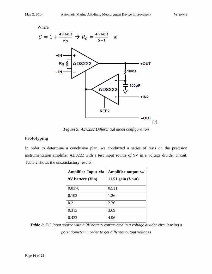
Where
𝐺 = 1 +49.4𝑘Ω
𝑅𝐺 𝑅𝐺 =
4.94𝑘Ω
𝐺−1 [9]
[7]
Figure 9: AD8222 Differential mode configuration
Prototyping
In order to determine a conclusive plan, we conducted a series of tests on the precision
instrumentation amplifier AD8222 with a test input source of 9V in a voltage divider circuit.
Table 2 shows the unsatisfactory results.
Amplifier Input via
9V battery (Vin)
Amplifier output w/
11.51 gain (Vout)
0.0378 0.511
0.102 1.26
0.2 2.36
0.313 3.69
0.422 4.96
Table 1: DC Input source with a 9V battery constructed in a voltage divider circuit using a
potentiometer in order to get different output voltages
May 2, 2014 Automatic Marine Alkalinity Measurement Device Improvement Version 3
Page 11 of 25
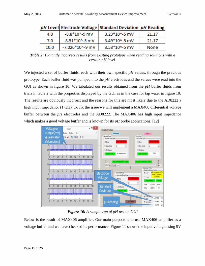
Table 2: Blatantly incorrect results from existing prototype when reading solutions with a
certain pH level.
We injected a set of buffer fluids, each with their own specific pH values, through the previous
prototype. Each buffer fluid was pumped into the pH electrodes and the values were read into the
GUI as shown in figure 10. We tabulated our results obtained from the pH buffer fluids from
trials in table 2 with the properties displayed by the GUI as in the case for tap water in figure 10.
The results are obviously incorrect and the reasons for this are most likely due to the AD8222’s
high input impedance (1 GΩ). To fix the issue we will implement a MAX406 differential voltage
buffer between the pH electrodes and the AD8222. The MAX406 has high input impedance
which makes a good voltage buffer and is known for its pH probe applications. [12]
Figure 10: A sample run of pH test on GUI
Below is the result of MAX406 amplifier. Our main purpose is to use MAX406 amplifier as a
voltage buffer and we have checked its performance. Figure 11 shows the input voltage using 9V

May 2, 2014 Automatic Marine Alkalinity Measurement Device Improvement Version 3
Page 12 of 25
battery with potentiometer connected in a voltage divider manner. We set our input at 399mV
and as shown in figure 12 had obtained an output of 399mV as we expected.
Figure 11: MAX406 input voltage
Figure 12: MAX406 output voltage
May 2, 2014 Automatic Marine Alkalinity Measurement Device Improvement Version 3
Page 13 of 25
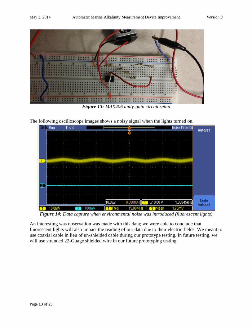
Figure 13: MAX406 unity-gain circuit setup
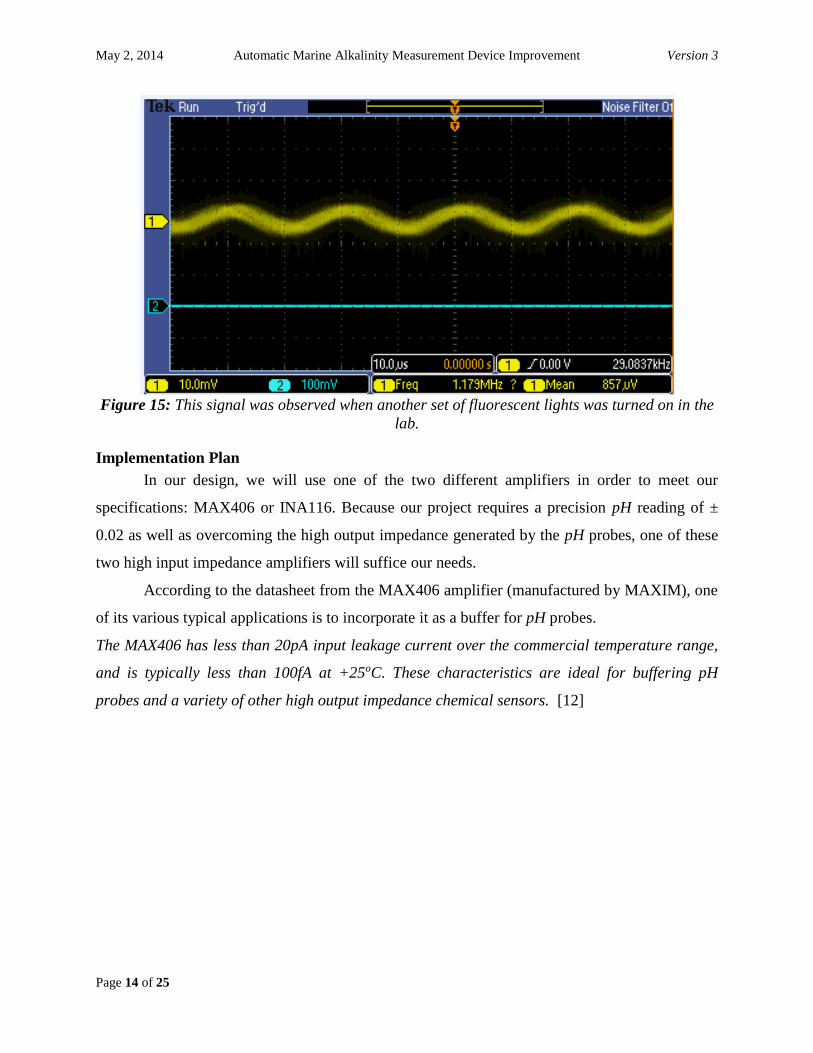
The following oscilloscope images shows a noisy signal when the lights turned on.
Figure 14: Data capture when environmental noise was introduced (fluorescent lights)
An interesting was observation was made with this data; we were able to conclude that
fluorescent lights will also impact the reading of our data due to their electric fields. We meant to
use coaxial cable in lieu of un-shielded cable during our prototype testing. In future testing, we
will use stranded 22-Guage shielded wire in our future prototyping testing.
May 2, 2014 Automatic Marine Alkalinity Measurement Device Improvement Version 3
Page 14 of 25
Figure 15: This signal was observed when another set of fluorescent lights was turned on in the
lab.
Implementation Plan
In our design, we will use one of the two different amplifiers in order to meet our
specifications: MAX406 or INA116. Because our project requires a precision pH reading of ±
0.02 as well as overcoming the high output impedance generated by the pH probes, one of these
two high input impedance amplifiers will suffice our needs.
According to the datasheet from the MAX406 amplifier (manufactured by MAXIM), one
of its various typical applications is to incorporate it as a buffer for pH probes.
The MAX406 has less than 20pA input leakage current over the commercial temperature range,
and is typically less than 100fA at +25oC. These characteristics are ideal for buffering pH
probes and a variety of other high output impedance chemical sensors. [12]

May 2, 2014 Automatic Marine Alkalinity Measurement Device Improvement Version 3
Page 15 of 25
Figure 16: Unity-gain Amplifier MAX406
The circuit in figure 16 eliminates expensive low-leakage cables that often connect pH probes to
meters. This schematic also proposes the use of a low-cost coaxial cable (a stranded coaxial
cable will be more optimal to block environmental noise) to carry the voltage directly to the A/D
converter to then be read in the software. However, there are two things to consider, A/D range
and proper measurement. As mentioned earlier, these voltages will be measured using an
oscilloscope. Also, if the output voltage from the buffer does not meet the A/D converter range
(up to ±20V on a differential configuration and ±10V for single-ended mode), it will have to be
amplified to meet that criteria. In theory, if the voltage needs to be amplified, any amplifier
would work fine, however by using the MAX406 we would be eliminating the high input
impedance. Furthermore, the proposed power supply for this circuit calls for a 3 volt battery to
power up the probe and MAX406 which can be accommodated to a maximum of 10 volts
because that is in the range of the MAX406 power supply.
The other option is to use the instrumentation amplifier INA116 manufactured by Burr-
Brown. Once again, the reason why we are choosing this component is because one of its few
typical applications is pH measurement. Additionally, the extremely high input impedance of
INA116 (1015Ω) will make it a great candidate to implement in our project. Figure 17 shows the
complete schematic of this chip.

May 2, 2014 Automatic Marine Alkalinity Measurement Device Improvement Version 3
Page 16 of 25
Figure 17: Instrumentation Amplifier INA116 schematics
The advantage of choosing this amplifier (Figure 17) over the MAX406 is that the INA116 has
the ability to set the gain in order to meet analog-to-digital converter range.
The gain (G) can be derived by choosing an appropriate value for RG. It is defined as follows:
𝐺 = 1 +50𝑘Ω
𝑅𝐺
Figure 18: shows the actual connection of the pH electrodes to the instrumentation-Amplifier
INA116; however, in our project, we’re using the flow-through electrodes.

May 2, 2014 Automatic Marine Alkalinity Measurement Device Improvement Version 3
Page 17 of 25
Testing Plan
Since our project will be based mostly on the accurate reading of the pH electrode from
an electronics perspective, we will have to perform several tests on the components obtained in
order to succeed the task. Our experimenting and testing will consist of:
1. Setting up the circuit on a breadboard for the MAX406 unity-gain amplifier.
2. Using a pH meter (figure 19) which will serve as a monitoring device for the accurate pH
reading of the solution we want to measure.
3. Running tests with different pH solutions using the bread boarded prototypes of the
amplifiers and checking to see if we obtain a correct reading in respect to the pH values
(59.16mV/pH.)
4. After getting the appropriate results using such amplifiers, we will work on a vector
board so that the prototype of that specific circuit can be incorporated into the current
prototype device implemented by Dr. Hintz (figure 20)
5. Running a series of tests on the current prototype device using buffers fluids with a
known pH so that the output we obtain is the same.
6. If we detect a repetitive inaccuracy and/or error during this procedure that cannot be
fixed, we’ll change the amplifier to the instrumentation amplifier INA116
Figure 19: pH meter to determine the exact pH value of the solution to be measured
May 2, 2014 Automatic Marine Alkalinity Measurement Device Improvement Version 3
Page 18 of 25
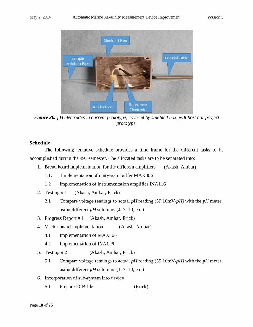
Figure 20: pH electrodes in current prototype, covered by shielded box, will host our project
prototype.
Schedule
The following tentative schedule provides a time frame for the different tasks to be
accomplished during the 493 semester. The allocated tasks are to be separated into:
1. Bread board implementation for the different amplifiers (Akash, Ambar)
1.1. Implementation of unity-gain buffer MAX406
1.2 Implementation of instrumentation amplifier INA116
2. Testing # 1 (Akash, Ambar, Erick)
2.1 Compare voltage readings to actual pH reading (59.16mV/pH) with the pH meter,
using different pH solutions (4, 7, 10, etc.)
3. Progress Report # 1 (Akash, Ambar, Erick)
4. Vector board implementation (Akash, Ambar)
4.1 Implementation of MAX406
4.2 Implementation of INA116
5. Testing # 2 (Akash, Ambar, Erick)
5.1 Compare voltage readings to actual pH reading (59.16mV/pH) with the pH meter,
using different pH solutions (4, 7, 10, etc.)
6. Incorporation of sub-system into device
6.1 Prepare PCB file (Erick)

May 2, 2014 Automatic Marine Alkalinity Measurement Device Improvement Version 3
Page 19 of 25
6.2 Implement design into current prototype (Akash, Ambar)
7. Progress Report # 2 (Akash, Ambar, Erick)
8. System Testing (Akash, Ambar, Erick)
9. Mixing Chamber (extra credit) (Akash, Ambar, Erick)
1 2 3 4 5 6 7 8 9 10 11 12 13 14
1. Bread board Implementation
1.1 Implementation of unity-gain buffer MAX406
1.2 Implementation of instrumentation…
2. Testing # 1
2.1 Compare voltage readings of actual pH…
3. Progress Report # 1
4. Vector board implementation
4.1 Implementation of MAX406
4.2 Implementation of INA116
5. Testing # 2
6. Incorporation of sub-system into device
6.2 Implement design into current prototype
7. Progress Report # 2
8. Final System Testing
9. Mixing Chamber (extra credit)
Project Plan

May 2, 2014 Automatic Marine Alkalinity Measurement Device Improvement Version 3
Page 20 of 25
Appendix
The following appendix shows the different components of the existing prototype as well
as an overview of the whole system.
Relay Board
Figure 21: Relay board block diagram
The above diagram is for the relay board USB-ERB08 which acts as a series of switches
in order to perform functions such as closing or opening the solenoid valves or for operation of
pumps. The switches have two modes to set the relay control logic polarity for each relay bank
for invert or non-invert. By default, the switches are shipped with all banks configured for non-
inverted logic. There are two modes associated the switches; non-invert and invert. In non-invert
mode, when “0” is written or read back via the USB bus, the relays are not energized. In invert
mode, when “0” is written or read back via the USB bus, the relays are energized. The USB bus
reads back the switch settings for polarity. [8]

May 2, 2014 Automatic Marine Alkalinity Measurement Device Improvement Version 3
Page 21 of 25
Analog-to-Digital Converter
Figure 22: A/D converter block diagram
The USB-1408FS is a USB 2.0 full-speed analog input and digital I/O data acquisition device
supported under popular Microsoft Windows operating systems. It is designed for USB 1.1 ports,
and was tested for full compatibility with both USB 1.1 and USB 2.0 ports. The USB 1408-FS
features eight analog inputs, two 12-bit analog outputs, 16 digital I/O connections, and one 32-bit
external event counter. The analog inputs are software configurable for either eight 13-bit single-
ended inputs or four 14-bit differential inputs. The digital I/o lines are independently selectable
as input or output in two 8-bit ports. The 32-bit counter can count TTL pulses. A SYNC
(synchronization) I/O line allows one to pace the analog input acquisition of one USB module
from the clock output of another. No external power is required for operation other than the USB
port to a computer. The purpose of the above A/D converter is to ensure a reading from the pH

May 2, 2014 Automatic Marine Alkalinity Measurement Device Improvement Version 3
Page 22 of 25
probe to the GUI and this required a higher voltage which is provided by the AD8222
instrumentational amplifier. [9]
Level 0 design of current device
Figure 23: level 0 design of overall long term device
May 2, 2014 Automatic Marine Alkalinity Measurement Device Improvement Version 3
Page 23 of 25
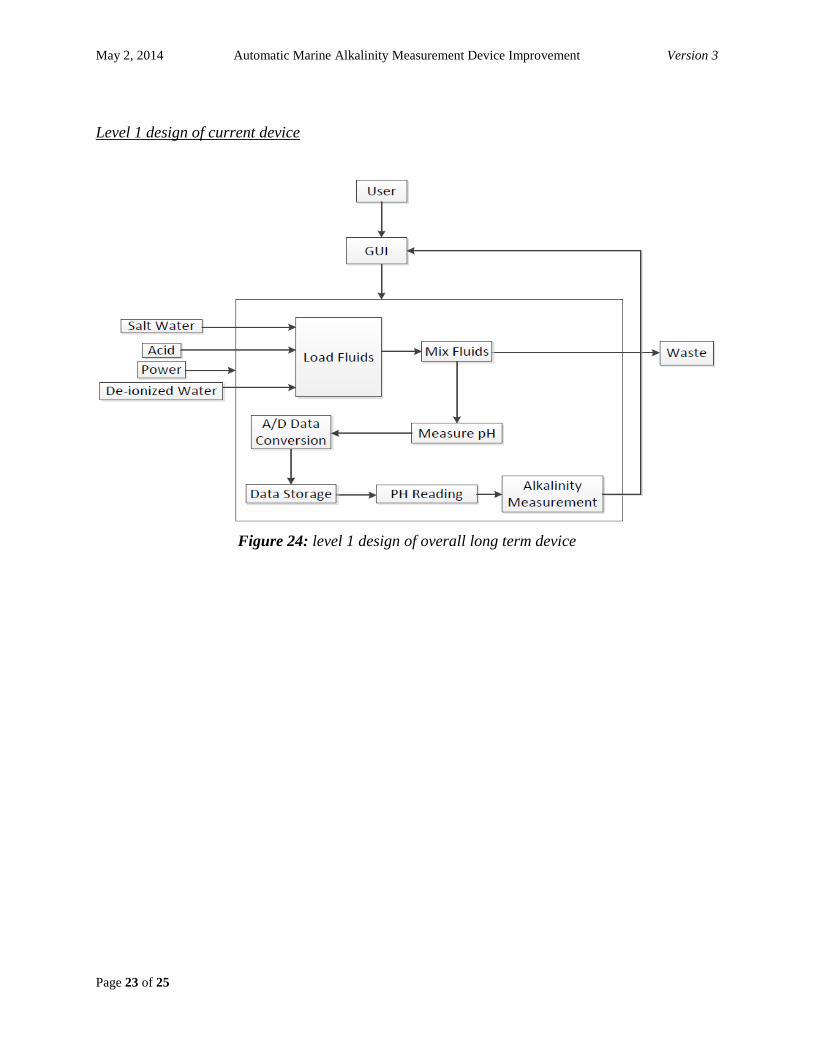
Level 1 design of current device
Figure 24: level 1 design of overall long term device
May 2, 2014 Automatic Marine Alkalinity Measurement Device Improvement Version 3
Page 24 of 25
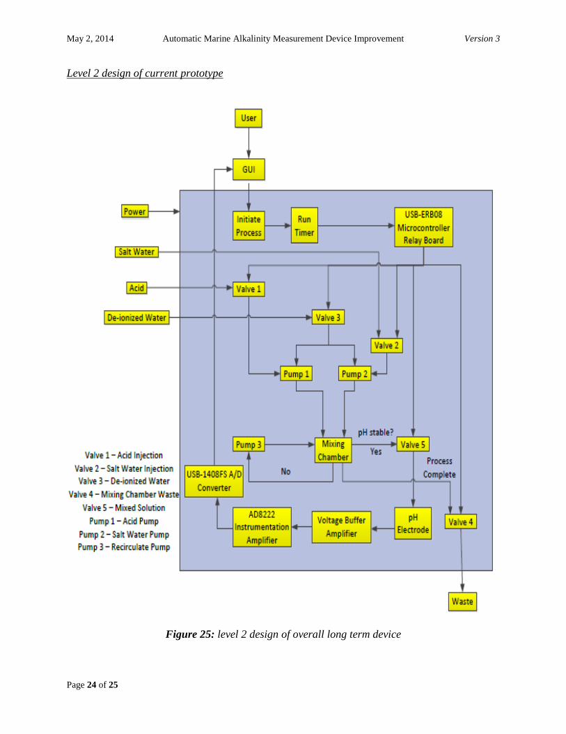
Level 2 design of current prototype
Figure 25: level 2 design of overall long term device
May 2, 2014 Automatic Marine Alkalinity Measurement Device Improvement Version 3
Page 25 of 25
References
[1] Allaboutcircuits.com, 'pH measurement : Electrical Instrumentation Signals', 2014. [Online].
Available: http://www.allaboutcircuits.com/vol_1/chpt_9/6.html. [Accessed: 02- May- 2014].
[2] Analog.com, 'Analog Devices | Semiconductors and Signal Processing ICs', 2014. [Online].
Available: http://www.analog.com. [Accessed: 01- May- 2014].
[3] Elmhurst.edu, 'pH Scale', 2014. [Online]. Available:
http://www.elmhurst.edu/~chm/vchembook/184ph.html. [Accessed: 02- May- 2014].
[4] Facstaff.bucknell.edu, 'Unity Gain Buffer Amplifier', 2014. [Online]. Available:
http://www.facstaff.bucknell.edu/mastascu/elessonshtml/OpAmps/OpAmp3Note1Buffer.html.
[Accessed: 02- May- 2014].
[5] J. Kim, K. Sung and G. Chae, 'Unmanned automatic alkalinity measuring system and
method', US20130316460 A12014.
[6] K. Hintz and C. Hintz, 'Alkalinity Determination', US20100210026 A12010.
[7] Mccdaq.com, 'Data Acquisition (DAQ) from Measurement Computing', 2014. [Online].
Available: http://www.mccdaq.com. [Accessed: 01- May- 2014].
[8] Microcontrollers.com, 'microcontrollers.com - Microcontrollers Resources and Information.',
2014. [Online]. Available: http://www.microcontrollers.com. [Accessed: 01- May- 2014].
[9] Precision, Dual-Channel Instrumentation Amplifier, 1st ed. Norwood: Analog Devices, 2010.
[10] USB-1208FS/LS/1408FS Series: 12-bit and 14-bit Multifunction Devices with 8 Analog
Inputs, 2 Analog Outputs, 1st ed. Measurement Computing, 2013.
[11] USB-ERB08, 1st ed. Measurement Computing, 2010.
[12] 1.2uA Max, Single/Dual/Quad, Single-Supply Op Amps, 2nd ed. Maxim, 2014.


![CERTIFICATE.pdf · AOAC 973.50 APHA 4500-N03 -B APHA 52200 Materials/ Products tested Effluent/Water 08 Type of test] Properties measured/ Ranqe of measurement Alkalinity Arsenic](https://static.fdocuments.us/doc/165x107/5ea77f8e1966f576e809019f/certificatepdf-aoac-97350-apha-4500-n03-b-apha-52200-materials-products-tested.jpg)


