
Improving Man's Effectiveness Through Electronics · TEXAS INSTRUMENTS Improving Man's...
69
,t,\\ ,JJ . " // TEXAS INSTRUMENTS Improving Man's Effectiveness Through Electronics AFLC RAFB, GA REPRINT Model 980 Computer Terminal User's Guide· Model 733 ASR/KSR Dat;) Terminal MANUAL NO. 943009-9701 ORIGINAL ISSUE 15 AUGUST 1974 INCLUDES CHANGE 1 ............... 1 SEPTEMBER 1975 BASIC AND ALL CHANGES HAVE BEEN MERGED TO MAKE THIS A COMPLETE PUBLICATION. ... eC'(J dfJ1 ' Date' iled & 1 ntIs 30 :JUf)V!?t7 Digital Systems Division
Transcript of Improving Man's Effectiveness Through Electronics · TEXAS INSTRUMENTS Improving Man's...

,t,\\ ,JJ .
~~V\~~==~============~3=,/~S~S=~~~='_='~~I~=-~~h==/==~
"
//
TEXAS INSTRUMENTS
Improving Man's Effectiveness Through Electronics
AFLC RAFB, GA REPRINT
Model 980 Computer
Terminal User's Guide· Model 733 ASR/KSR Dat;) Terminal
MANUAL NO. 943009-9701 ORIGINAL ISSUE 15 AUGUST 1974
INCLUDES CHANGE 1 ............... 1 SEPTEMBER 1975
BASIC AND ALL CHANGES HAVE BEEN MERGED TO MAKE THIS A COMPLETE PUBLICATION.
...
Da~. eC'(J dfJ1 ' ~7
Date' iled & 1 ntIs 30 :JUf)V!?t7 ~./6~
Digital Systems Division

(£) Texas Instruments Incorporated 1975 All Rights Reserved
The information and/or drawings set forth in this document and all rights 1n and to inventions disclos.ed herein and patents which might be granted thereon disclosing or employing the, materials, methods, techniques or 'apparatus described herein are the exclusive property of Texas Instruments Incorporated.
No disclosure of the information or drawings shall be made to any other person or organization without the pri~r consent of Texas Instruments Incorporated.
INSERT LATEST CHANGED PAGES DESTROY SUPERSEDED PAGES
LIST OF EFFECTIVE PAGES Note: The portion of the text affected by the changes is indicated by a vertical bar in the outer marglns,of the page.
Model 980 Computer Terminal User's Guide Model 733 ASR/KSR Data Terminal (943009.9701)
Original Issue 15 August 1974 Change'! 1 September 1975 (ECN 393175)
Total number of pa:ges in this publication is 70 consisting of the following:
PAGE CHANGE NO. NO.
PAGE NO.,
CHANGE NO.
PAGE NO.
CHANGE NO.
. Cover 1 0'
'EIT. Pages 1 ,-
iii· v . Ok 11·0·1·6 0('""
I 2.1 ·2-6 0-, 2·7/2,8 1 ..,.."~
, 2·9 . 2·18 OC .~, 3·1 - 3·8 0/ 1,1 4-1 ·4-20 0/ ,
5·[ . 5·2 0"'-I Alphabetical Index Div. 1 .(c '
.Index·\ . Index-6 ! (,
User's Resp ! Bus. Reply. 0 Cover Blank 0 Cover L .
;" J
,
(
f
(
(
~ ____ 9_4_30_0~9_-_9_70_1 _______________________________________________ _
Paragraph
1.1 1.2 1. 2. 1 1. 2. 2 1. 2.3 1. 2.4 1. 2. 5 1. 2. 6
2. 1 2.2 2. 2. 1 2.2.2 2.3 2. 3. 1 2.4 2.4. 1 2.4.2 2.4. 3 2.4.4 2.4.5 2.5 2.6
3. 1 3.2 3.2. 1 3.2.2 3.2.3 3.3
TAB LE OF CONTENTS
Title
SECTION 1. GENERAL DESCRIPTION
Description Specifications.
Data Format and Transmis sion Printer ••••• Communication Line Interface Physical Power Requirements Tape Transport •• , •
SECTION II. INSTALLATION
General .••.• Model 733 ASR
Paper Loading Cas sette Installation
Model 733 KSR .. Pa pe r Loading
Interface Circuit Card Module Addres s Selection. Baud Rate Selection .•••• Parity Enable and Selection •• Word Length Selection Stop Bit Selection
Interface Cables .•. Interface Connections. "
SECTION Ill.· OPERATION
General. II •••••••••••••••••
Terminal Controls and Indicators •• On-line / Off Switch (Figure 3-1) • Keyboard Controls ••.••••••• Upper Switch Panel (ASR Only)
Operation II •••••••••••••••••
iii
. . · · · . · · ·
. . . · · ·
Page
1-1 1-2 1-2 1-2 1-2 1-3 1-4 1-4
2-1 2':'1 2-5 2-6 2-7 2-7 2-7 2-7 2-11 2-12 2-13 2-13 2-14 2-14
3-1 3-1 3-1 .3-2 3-2 3-8
Digital Systems Divis!on_
~ ____ 9_4_3_0_09_-_9_7_0_1 _________________________ ~ ____ ~ ________ . ____ __
Paragraph
4. 1 4.1.1 4.1.2 4.1.3 4.2 4.2. 1 4.2.2 4.3 4. 3. 1 4.4 4.4. 1 4.4.2
Figure
1 -1
2-1
2-2 2-3 2-4
2-5 2-6 2-7
3 -1 3-2
4-1 4-2 4-3 4-4 4-5
TABLE OF CONTENTS (Continued)
Title
SECTION IV. INTERFACE DESCRIPTION
General ••••••• Communications Module Interface Cable Ba ud Rate •••••••••
Signal Definitions ••••••
. . . .
Computer to Interface (Figure 4-3). Interface to Computer (Figure 4-4).
Remote Device Control (ASR Only) • Functional Descriptions .••••
Interface Operation ••••• Computer to Terminal
/ Terminal to Compute.r . · .
. .
. .
. . SECTION V. PROGRAMMING REQUIREMENTS
LIST OF ILLUSTRATIONS
Title
. .
Model 733 ASR/KSR Data Terminals. . . . . . . . . . . . . . Model 733 ASR Data Terminal Outline
Dimensions and Weight ••• Pa pe r Loading •••••••••••••••••• Ca sse tte Ins talla ti on •••••••••••• Model 733 KSR Data Terminal Outline
Dimensions and Weight • Interface Cable Data Adapter Cable Data ••••• Interface Connectors ••••••
· . .' .
· . . . • • 41 •
Terminal ON-LINE/OFF Switch and Power Switch Upper Switch Panel •••••••••••
Bit and Character Time Definitions Interface Data ••••••• . . . . WDS Data Word Format •••••••• RDS Data Word Format •••••••• Status Character Bit Definition •••
. . . . . . " • 41 • • " • •
• • • • AI •
Page
4-1 4-2 4-2 4-2 4-3 4-3 4-6 4-9 4-11 4-17 4-17 4-18
Page
1-0
2-3 2-5 2-6
2-9 2-15 2-16 2-17
3-1 3-3
4-1 4 .. 3 4-5 4-6 4-15
iv Digital Systems Division
(
I
(
(

~_' ___ 9~4_3_0~0_9_-_9_7_0_1 ____________ ~ ______________________________ ~ __ _
Table
1-1 1-2
2-1 2-2 2-3 2-4 2-5
3-1 3-2
5-3
4-1 4-2
LIST OF TABLES
Title
Printer Specifications ..••• Tape Transport Specifications
Module Address Selection ••• Baud Rate Selection" •• Module Parity Selection Word Length Selection • .stop Bit Selection ••••
. . • •
Tape Control Switches (Switch Pa~el Top Row) • PLAYBACK/RECORD Control Switches
(Switch Panel Middle Row) ••.•••••••••• Device Function Switches (Switch Panel Bottom Row).
Signal to Nomenclature Cross Reference. Remote Device Control Functions .•••••
. .
Page
1-3 . 1-4
2-11 2-12 2-12 2-13 2-13
3-4
3-5 3-8
4-3 4-10
v Digital Systems Division
~---,-.-----------~-'1:Y ___ ~3009-9701
(
(
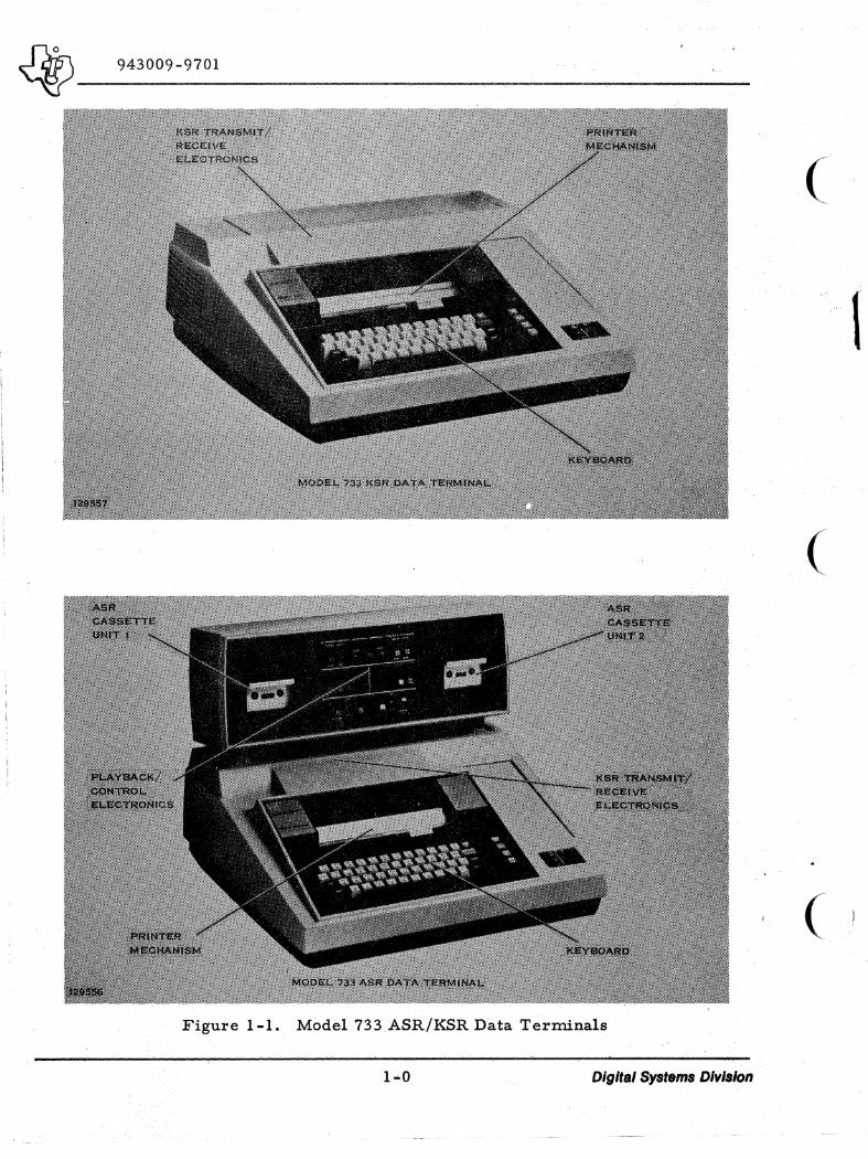
Figure 1-1. Model 733 ASR/KSR Data Terminals
1-0 Digital Systems Divis/on
I
i!
I I ! I i I I
1\
!
1
,
~ __ ' __ 9_4_3_0_0_9_-_9_7_0l ___________________________________ ~ ____________ ___
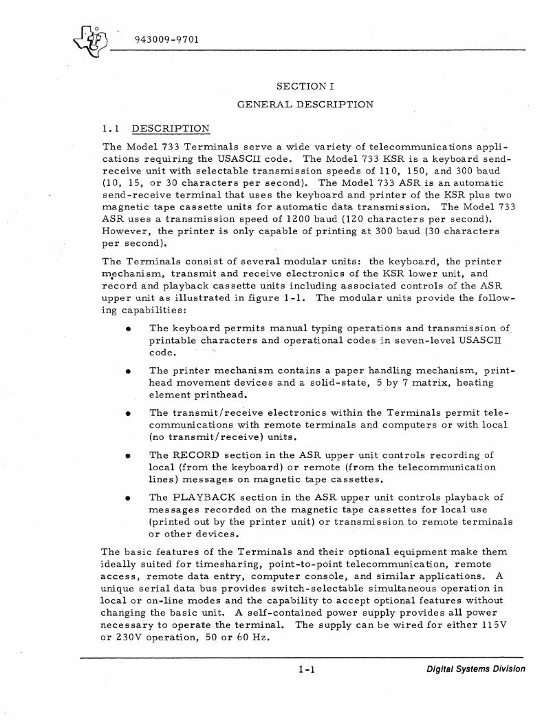
1. 1 DESCRIPTION
SECTION I
GENERAL DESCRlPTION
The Model 733 Terminals serve a wide variety of telecommunications applications requiring the USASCII code. The Model 733 KSR is a keyboard sendreceive unit with selectable transmission speeds of 11 0, 150, and 300 baud (l0, 15, or 30 characters per second). The Model 733 ASR is an automatic send-receive terminal that use s the keyboard and printer of the KSR plus t\vo magnetic tape cassette units for automatic data transmission. The Model 733 ASR uses a transmission speed of 1200 baud (120 characters per second). However, the printer is only capable of printing at 300 baud (30 characters per second).
The Terminals consist of several modular units: the keypoard, the printer m.echanism, transmit and receive electronics of the KSR lower unit, and record and playback cassette units including associated controls of the ASR upper unit as illustrated in figure 1-1. The modular units provide the following capabilities:
• The keyboard permits manual typing operations and transmission of, printable characters and operational codes in seven-level USASCII code.
• The printer mechanism contains a paper handling mechanism, printhead movement devices and a solid-state, 5 by 7 matrix, heating element printhead.
• The transmit/rec~ive electronics within the Terminals permit telecommunications with remote terminals and computers or with local (no transmit/receive) units.
• The RECORD section in the ASR upper unit controls recording of local (from the keyboard) or remote (from the telecommunication lines) messages on magnetic tape cassettes.
• The PLAYBACK section in the ASR upper unit controls playback of messages recorded on the magnetic tape cassettes for local use (printed out by the printer unit) or transmission to remote terminals or other devices.
The basic features of the Terminals and their optional equipment make them ideally suited for timesharing, point-to-point telecommunica tion, remote access, remote data entry, computer console, and similar applications. A unique serial data bus provides switch-selectable simultaneous operation in local or on-line modes and the capability to accept optional features without changing the basic unit. A self-contained power supply provides all power necessary to operate the terminal. The supply can be wired for either 115V or 230V operation, 50 or 60 Hz.
1-1 Digital Systems Division

J}l$\----'--__ _ ~ _~43009-9701
The ASR Terminal includes a magnetic tape cassette systeIl). co.nsisting of two cassette transports, a record controller, and a playback controller. Either of the two transports may be used with the record controller or the playback controller but must operate alone or in opposite modes; i. e •• one· in the record mode and the other in the playback mode.
The tape recording format is serial-by-bit and serial-by-character. 86 characters to a physical block. The recording system permits the operator to edit or correct any line of data being recorded. It also allows correction of previously recorded lines, and blocks may be added to or !;leleted frorn a tape using a local mode tape duplicating process. In continuous tape format maximum storage capacity of a cassette using both sides of 310,000 characters. Data read from the tape is stored (one block at a time) in a buffer (memory) before being transmitted to a line or local device. The playback system allows data to be read from the tape, either continuously, a block at a time, or a character at a time. A block can also be reread any number of times to aid in recovering data in which a read error is detected. If the playback operation stops because of a read error, the erroneous block just read can be either skipped,. transmitted, or reread.
1.2 SPECIFICATIONS
1 • 2. 1 DA T A FORMAT AND TRANSMISSION
A single data bus routes data within the Terminal. Data transmitted from the Terminal is in a serial 8-bit-per-character format. The eight bits include a 7-bit USASCII character code plus an eighth bit which is used as an end-ofblock indicator in the ASR unit.
Transmission speed of the Model 733 KSR is switch selectable by the operator to 110 baud (10 characters per second), 150 baud (15 characters per second), or 300 baud (30 characters per second). The Model 733 ASRtran1ffhission speed is setat the factory to 1200 baud (120 characters per second).
An ON-LINE switch located on the switch panel controls the status of the entire Terminal. Refer to Section III of this manual for a description of the Terminal controls and indicators.
1. 2. 2 PRINTER
Refer to table 1-1 for the printer specifications.
1. 2.3 COMMUNICATION LINE INTERFACE
The standard line interface conforms to EIA Standard RS232C. The T~rrninal can receive, without error, signals with mark and space distortion of ~p to 45 percent. The minimum stop bit time for error-free reception at any speed is 0.6 of a normal bit time.
1-2 Digital Systems Division
(
I
(
(

~ ____ 9_4_3_0_0_9_-9_7_0_1 ____________________________________ ~ ______ __
Table 1-1. Printer Specifications
Specification
Printing Method
Line Length
Character Spacing
Line Spacing
Paper (TI Part Number 213714-0001 or 953167-0001
Platen
Carriage Return TiIne
Line Feed Time
Audible Alarm Time
Printable Characters
Carriage Return and Line ,Feed (CR/LF) ,
Visibility of Printed Lines
Print Contrast
1. 2. 4 PHYSICAL
I Value
5 x 7 dot matrix, electronically heated, on heat-sensitive paper
7.9 inches, 80 characters
O. 1 inch, character center to center
Six or three lines per inch (single or double spaced)
Roll, 8.5 inches wide by 3.625 inches maximum diameter (300 feet), heatsensitive
Friction feed
195 milliseconds maximum. Note: Terminal is inhibited for 200 milliseconds during the carriage return.
33 milliseconds maximum (single space), 66 milliseconds maximu.m (double space)
250 (±50) milliseconds on receipt of the BEL character
95
Automatic at column 81, no code is transmitted
At least 50 previous lines of print (including line and character being printed) are visible and unobstructed
Operator adjustable
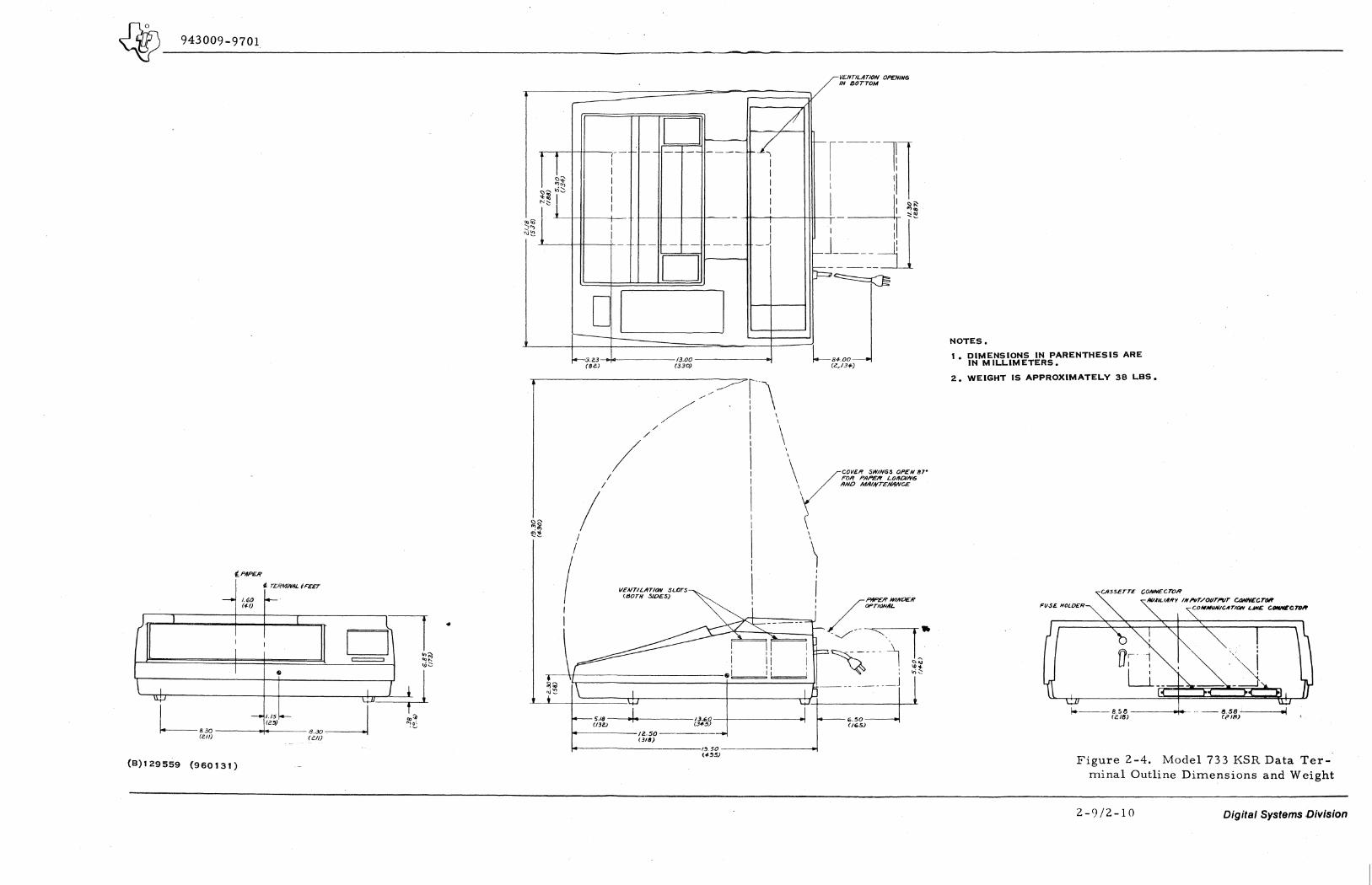
1. Dimensions ASR, figure 2 -1; KSR, figure 2-4
2. Weight 38 pounds KSR, 56 p~)Unds ASR, exclusive of all options
1-3 Digital Systems Division
. ./.
~. 943009-9701
-------------------------------------------------------------------------1.2.5 POWER REQUIREMENTS
1. Frequency
2. Voltage
3. Power
Normal operation wi th primary input power frequencies in the range of 48 to 62 Hz.
115 (+ 10% - 15%) volts RMS. It is possible to field-. modify the terminal to operate on 230 (+10% - 15%) volts RMS. Refer to Electronic Data Terminals Manual, part number 959227-9701.
Required primary input power at maximum rated voltage is 200 VA maximum
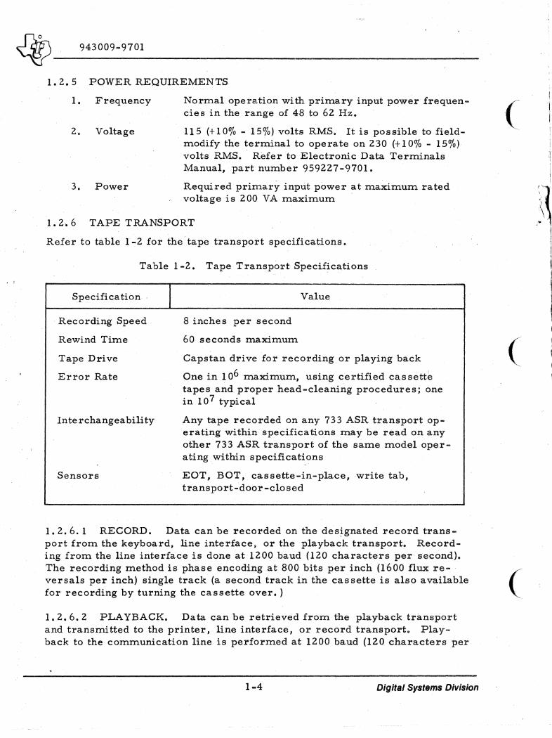
1.2.6 TAPE TRANSPORT
Refer to table 1-2 for the tape transport specifications.
Table 1-2. Tape Tran~port Specifications
Specifica tion
Recording Speed
Rewind Time
Tape Drive
Error Rate
In te rchangea bili ty
Sensors
I 8 inches per second
60 seconds maximum
Value
Capstan drive for recording or playing back
One in 106 maximum, using certified cassette tapes and proper head-cleaning procedures; one in 107 typical
Any tape recorded on any 733 ASR transport operating within specifications may be read on any other 733 ASR transport of the same model operating within specificati.ons
EOT, BOT, cassette-in-place, write tab, transport-door-closed
(
(
1.2.6.1 RECORD. Data can be recorded on the des~gnated record transport from the keyboard, line interface, or the playback transport. Recording from the line interface is done at 1200 baud (120 characters per second). The recording method is phase encoding at 800 bits per inch (1600 flux re-versals per inch) single track (a second track in the cassette is also available ( for recording by turning the cassette over. ) .
1.2.6.2 PLAYBACK. Data can be retrieved from the playback transport and transmitted to the printer, line interface, or record transport. Playback to the communication line is performed at 1200 baud (120 characters per
1-4 Digital Systems Division
~ ____ 9_4_3_0_0_9-_9_7_0_l ______________________________________________ __
second). When transferring data from a playback transport to the line interface or page printer, playback is inhibited for 200 milliseconds following the carriage return character in the line tape format (carriage return character time is included in the 200 milliseconds) or at the end of each block in either format. Local high speed duplication is performed at a 2500 baud rate (250 characters per second). If a printout is desired during duplicating, then the maximum speed is limited to 300 baud (30 characters per second) due to the printer.
1-5/1-6 Digital Systems Division

(
(
(

~ ____ 9_4_3_0_0_9_-_9_7_01 ________________________________________________ __
2.1 GENERAL
SECTION II
INSTALLATION
This section provides the instructions to install the Terminal and prepare it for use. Obtain a copy of Electronic Data Terminals Manual, part number 959227-9701 for reference during installation.
2.2 MODEL 733 ASR
Refer to figure 2-1 for the Terminal outline dimensions and weight. To unpack and install the Terminal, select an appropriate location and proceed as follows:
1. Remove the KSR (lower) unit from its shipping container and place it on the accessory terminal stand or other flat surface. (Leave the keyboard cover closed. )
2. Remove the ASR (upper) keyboard unit from its shipping carton and carefully place it, display panel down, on a flat surface.
3. Facing the hottom of the upper unit, loosen the four 10-32 screws about 4-1/2 turns (these are the screws with the largest heads). The four screws should protrude 1/8 to 3/16 inch.
4. Note the two keyhole slots in both pedestals at the top rear of the KSR (lower) unit. Pick up the ASR upper unit and place it on the two pedestals so that the heads of the four screws loosened in step 3 enter the large portion of the slots. Ensure that the upper unit controls face the keyboard.
5, Check that the base of the upper unit is resting squarely on the pedestals. Now slide the upper unit to the rear so the screws locate at the narrow part of the keyhole slots.
Before proceeding, check that the upper unit is in proper position by trying to lift it from the KSR unit. It will not lift from the lower unit if properly located.
6. Slowly raise the keyboard cover to its uppermost position. The four upper unit mounting screws are now accessible through the four rectangular shaped holes in the metal support plate.
Tighten the four mounting screws securely. Lower the keyboard cover.
2-1 Digital Systems Division

J}nS\ ____ _ ~ 943009-9701
7. Locate ASR/KSR interconnecting cable 959371-1 and the terminal maintenance kit. (This kit contains alcohol and cotten swabs for cleaning the terminal components.) Within this kit find a plastic bag containing four screws (two 4-40 x 3/8 and two 4-40 x S/8). These screws are used to fasten the ASR/KSR interconnecting cable to the respective assemblies.
8. Plug the connector marked PI onto the cassette connector (figure 2-1) of the ASR unit. The key slot must be positioned up to mate with the tab on the cover. Ensure that the connector is inserted as far as the cover will allow. Secure the connector with the two shorter screws (4-40 x 3/8) through the holes in the connector ears.
9. Dress the cable to the left (viewed from the rear) in a IIC" shaped configuration close to the unit and plug the connector marked P3 onto the cassette connector (figure 2-1) of theKSR unit. The key slot must be positioned up to mate with the key in the connector housing. Insert as far as possible. Secure this connector with the two longer screws (4-40 x 5/8) through the holes in the connector ears.
10. Plug the small white connector (P13) on the cable extending from the fan into the connector next to the fuse and power cord outlet on the KSR unit. It is keyed and may be inserted only one way. A protective clip may have to be removed.
11. Ensure tp.at the POWER switch is OFF and connect the AC power cord to an AC power source.
12. . Carefully lift the keyboard cover and verify the following switch positions:
SPEED - HI
DUPLEX - FULL
ADC - ON
LINE FEED - 1
PARITY - ODD
13. Close the keyboard cover. In the RECORD CONTROL section of the ASR unit, set TAPE FORMAT switch to CONT.
2-2 Digital Systems Division
(
(
(

· ~ __ ~94~3~O~09~-~9'~70~1 ______________________________________ ------------------------______________________________________________ ___
PI/PER
TERMINIIL IFEET
---10 1.60 I-(4-0
D I I D --J I IL .<\J
'" 't
) 1 (
I D I = s
\ I I LJ
L,~ - 1.65 f- .830~ t ... '" C4-Z-) ~~
(ell) (ell)
(8)129558 (960132)
i ~~ .!:!
~~ r ~" '" ~ ~ ., '" I
~~ 1 I\J~
r-
i--I I I I I
-i-I
I --
[ I .'--.
1+-3.23 (8e)
--
t----
/ /
/
/ /
/ I
I
D -- --
t-- t----
D
13.00 (330)
---
1---- --
I
\
\
-
VENT/LilT/ON O,P, '£MNG IN BOTTOM
V ~----l, I 'I I .
I • 'I I I i I
I \: I I
-
\ I I I
I Ii f-j ~:- __ --l
I--
\ FOIf P/PP£1f LOAOING AIVO MA/NTENIINC£
\ (WVER SWINGS OPEN 87'
\
\ \
\ F-'I9PER
WINLJER OF'Tk"lAlI9L
! VENT/LIITION SL(lTS (80TH SlOES)
5.18- - ~-.----- -13.60--+--(/3<') _ __ . __ 14-.50-----"(3'-'~-=5~)--+
______ ~(:=3~68~) __ ZI.75 _________ --'=~ (S5aJ
5.85 (/~~)
NOTES:
1. DIMENSIONS IN PARENTHESIS ARE IN MILLIMETERS.
2. WEIGHT IS APPROXIMATELY 56 Les.
C//5S£TT£ CONNECTOR /i(I,tILlIfRY /N"fIT/OVT/-Vr C~£CTOR
FUS£ HOLDER
858 lr.:..18)
COMMVNICIITION LINE CONNECTOR
Figure 2-1. Model 733 ASR Data Terminal Outline Dimensions and Weight
2-3/2-4 Digital Systems Division
~ 943009-9701 ----------------------------------------------------------------~--
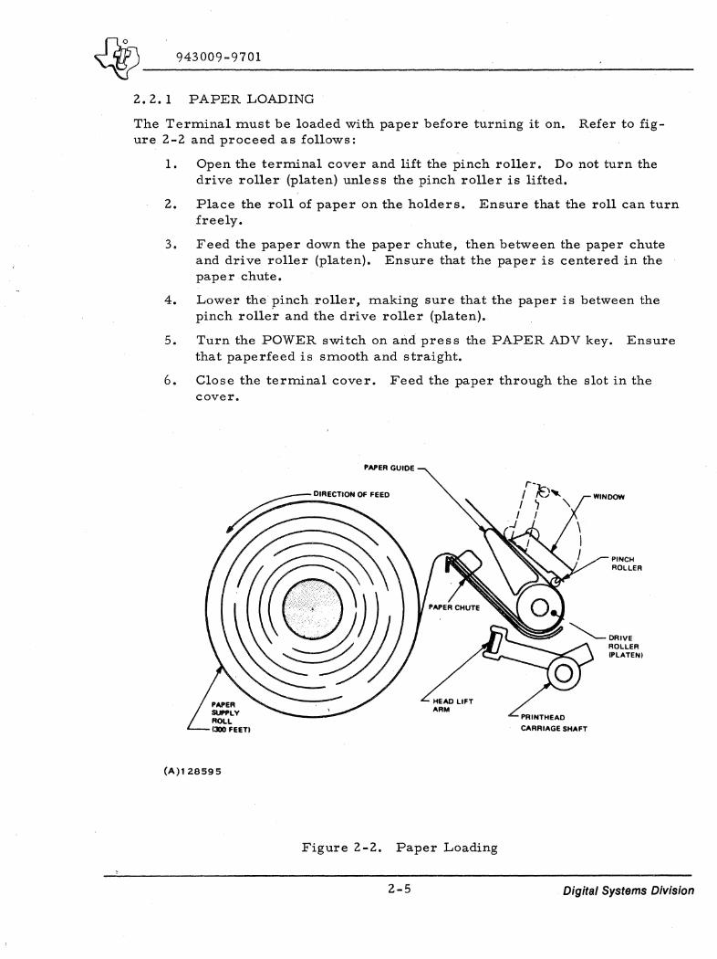
2.2. 1 PAPER LOADING
The Terminal must be loaded with paper before turning it on. Refer to figure 2-2 and proceed as follows:
1. Open the terminal cover and lift the pinch roller. Do not turn the drive roller (platen) unless the pinch roller is lifted.
2. Place the roll of paper on the holders. Ensure that the roll can turn freely.
3. Feed the paper down the paper chute, then between the paper chute and drive roller (platen). Ensure that the paper is centered in the paper chute.
4. Lower the pinch roller, making sure that the paper is between the pinch roller and the drive roller (platen).
5. Turn the POWER switch on and press the PAPER ADV key. Ensure that paperfeed is smooth and straight.
6. Close the terminal cover. Feed the paper through the slot in the cover.
(A)128595
PAPER GUIDE
HEAD LIFT ARM
Figure 2-2. Paper Loading
2-5
r-I ~) ..... I ~ " I I
-1
PRINTHEAD
CARRIAGE SHAFT
PINCH ROLLER
Digital Systems Division

~ ____ 9_4_3_0_09_-_9_7_0_1 ___________ .. __ ,_. _______ _
2.2.2 CASSETTE INSTALLA TION
To install or remove a magnetic tape cassette, refer to figure 2-3 and proceed as follows:
1. Open the transport door.
NOTE
Letter designating the side of the cas sette called out must be facing operator when the cassette is properly installed.
2. Insert the cassette with the tape side up (figure 2-3A).
3. Press the cassette down and in (figure 2-3B). Be sure that the capstan and reel rotors fit into the proper holes.
4. Close the transport door.
5. To remove a cassette from the transport, open the door to the first stop. A quick downward motion from that point will eject the cas:" sette from the transport.
CAl
(A)128596
- CASSETTE TRANSPORT DOOR
IBI
Figure 2 -3. Cassette Installation
2-6
PUSH CASSETTE TRANSPORT DOOR FORWARD TO CLOSE.
CASSETTE RETAINERS
Digital Systems Division
(
... , I
(
(
~ 943009-9701· --------------------------------------------------------------------
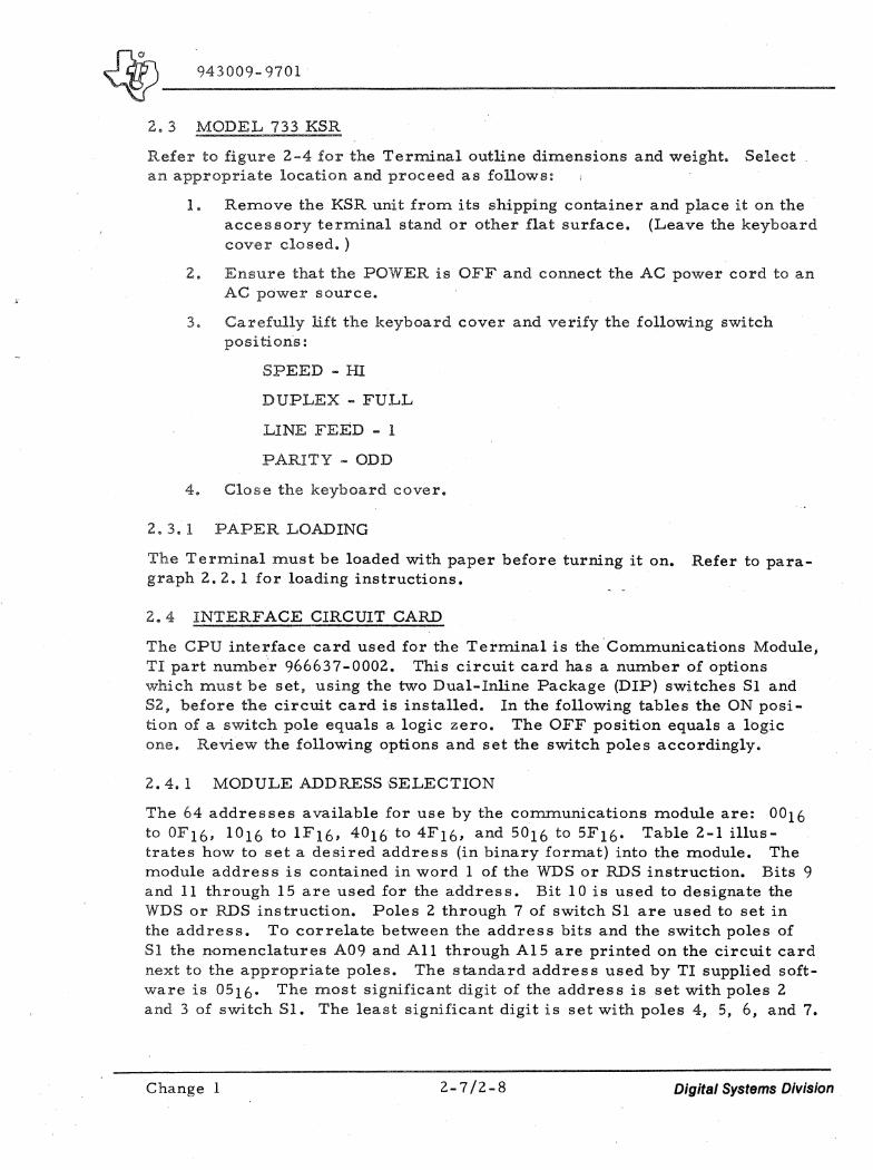
2. 3 MODEL 733 KSR
Refer to figure 2-4 for the Terminal outline dimensions and weight. Select an appropriate location and proceed as follows:
1. Remove the KSR unit from its shipping container and place it on the accessory terminal stand or other flat surface. (Leave the keyboard cover closed. )
2. Ensure that the POWER is OFF and connect the AC power cord to an AC power source.
3. Carefully lift the keyboard cover and verify the following switch positions:
SPEED - HI
DUPLEX - FULL
LINE FEED - 1
PARITY - ODD
4. Close the keyboard cover.
2.3. 1 PAPER LOADING
The Terminal must be loaded with paper before turning it on. Refer to paragraph 2. 2. 1 for loading instructions.
2.4 INTERFACE CIRCUIT CARD
The CPU interface card used for the Terminal is the Communications Module, Tl part number 966637-0002. This circuit card has a number of options which must be set, using the two Dual-Inline Package (DIP) switches Sl and S2, before the circuit card is installed. In the following tables the ON position of a switch pole equals a logic zero. The OFF position equals a lbgic one. Review the following options and set the switch poles accordingly.
2.4. 1 MODULE ADDRESS SELECTION
The 64 addresses available for use by the communications module are: 0016 to OF16. 1016 to IF16. 4016 to 4F16, and 5016 to 5F16. Table 2-1 illustrates how to set a desired address (in binary format) into the module. The module address is contained in word 1 of the WDS or RDS instruction. Bits 9 and 11 through 15 are used for the address. Bit 10 is used to designate the WDS or RDS instruction. Poles 2 through 7 of switch Sl are used to set in the address. To correlate between the address bits and the switch poles of S1 the nomenclatures A09 and All through Al5 are printed on the circuit card next to the appropriate poles. The standard address used by TI supplied software is 0516. The most significant digit of the address is set with poles 2 and 3 of switch S1. The least significant digit is set with poles 4, 5, 6, and 7.
Change 1 2-7/2-8 Digital Systems Division
(
(
(
~ __ 9:4~3~OO~9~-~97~O~l~ ____________________________________________________________________________________________________________ __
lPIlPER
il T£RMINRL ;FE£T
.- 1.(,0 1-. (</-1)
I ) r
d r I I
I =J
..
I $ I
~ I I Il+'
,~~ LB30 -- /.1St..-(2~)
(ell) (ell)
(B)129559 (960131)
- - --
L (
I I
"'* I I
't-~ I "'~ I
D ./ -- -- -----I I I I I I
L -I
I I
I
VEN TlLIITION OP£NING IN BOTTOM
~~r I -
I I ~~ 1 I '''' I N~ I I
r-J \ ~- 1-- t-- 1--- 1---- --'
D i--3.e3
( / /
(Be)
I /
/
D I
13.00 (330)
VEAlTILATION SLOTS CaOTI( SiDES)
I
, ~-~------------___ --&I
\ \
\ \ \
1:::---P
l-8
\
(
COV£1f SWINGS OPEN tJl" FOIf PAPER LOllal/V6
\ ANO MI///VT£N/I/VCE
\
\ \
)
--~~----------&+~~--+-------------~ ~. 50 ------t U~S)
t-----------12.50 -------(3111)
I---------------------/~. 50 ----.------_ (</-'5)
NOTES.
1. DIMENSIONS IN PARENTHESIS ARE IN M ILLIM ETERS •
2. WEIGHT IS APPROXIMATELY 38 LBS.
CO_ECTOR
IIfMILIII"'Y INNT/OUTPUT CONN£CTOH F(JS£ HOLDER COMMIINICATION LIN£ C_CTtNf
Figure 2-4. Model 733 KSR Data Terminal Outline Dimensions and Weight
2-9/2-10 Digital Systems Division

~--~----' 943009-9701 \.
Table 2-1. Module Address Selection
Switch Sl Switch Sl
Pole 2 Pole 3 Pole 4 Pole S Pole 6 Pole 7 MSD (A09) (All) LSD (AI2) (Al3) (A14) (AIS)
0 ON ON 0 ON ON ON ON --------------1 ON OFF 1 ON ON ON OFF
4 OFF ON 2 ON ON OFF' ON
S OFF OFF 3 ON ON OFF OFF
4 ON OFF ON ON
5 ON OFF ON OFF -------- - -- --------6 ON OFF OFF ON
7 ON OFF OFF OFF
8 OFF ON ON ON
9 OFF ON ON OFF
A OFF ON OFF ON
B OFF ON OFF OFF
C OFF OFF ON ON
D OFF OFF ON OFF
E OFF OFF OFF ON
F OFF OFF OFF OFF
NOTE: The standard address for TI supplied software is underscored with a dashed line.
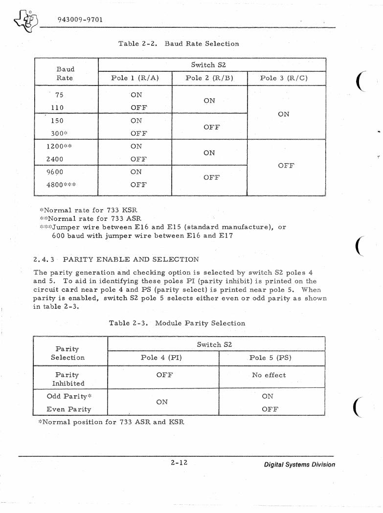
2.4.2 BAUD RATE SELECTION
The transmit and receive baud rate is determined by switch S2 poles 1, 2, and 3. To aid in identifying these poles the letters RIA, RIB, and RIC are printed on the circuit card next to the appropriate pole. Table 2-2 lists the switch positions requi'red for the various baud rates.
2-11 Digital Systems Division
~ ____ 9_4_3_0_0_9_-9_7_0_1 ______________________________ ~ ______________ __
Table 2 -2. Baud Rate Selection
Baud Rate Pole 1 (RIA)
75 ON
110 OFF
150 ON
300~:' OFF
1200~:":' ON
2400 OFF
9690 ON
4 8 0 0 ~:o:,,:, OFF
':'Normal rate for 733 KSR ,:o:'Normal rate for 733 ASR
Switch S2
Pole 2 (RIB)
ON
OFF
ON
OFF
Pole 3 (RIC)
ON
OFF
,:,,:o:'Jumper wire between E16 and E15 (standard manufacture). or 600 baud with jumper wire between E16 and E:l 7
2.4.3 PARITY ENABLE AND SELECTION
The parity generation and checking ()ption is selected by switch S2 poles 4 and 5. To aid in identifying these poles PI (parity inhibit) is printed on the circuit card near pole 4 and PS (parity select) is printed near pole 5. When parity is enabled, switch S2 pole 5 selects either even or odd parity as shown in table 2-3.
Table 2-3. Module Parity Selection
Parity Switch S2
Selection Pole 4 (PI) Pole 5 (PS)
Parity OFF . No effect Inhibited
Odd Parity':' ON ON
Even Parity OFF
':'Normal position for 733 ASR and KSR
2-12 Digital Systems Division
(
(
(
~. 943009-9701
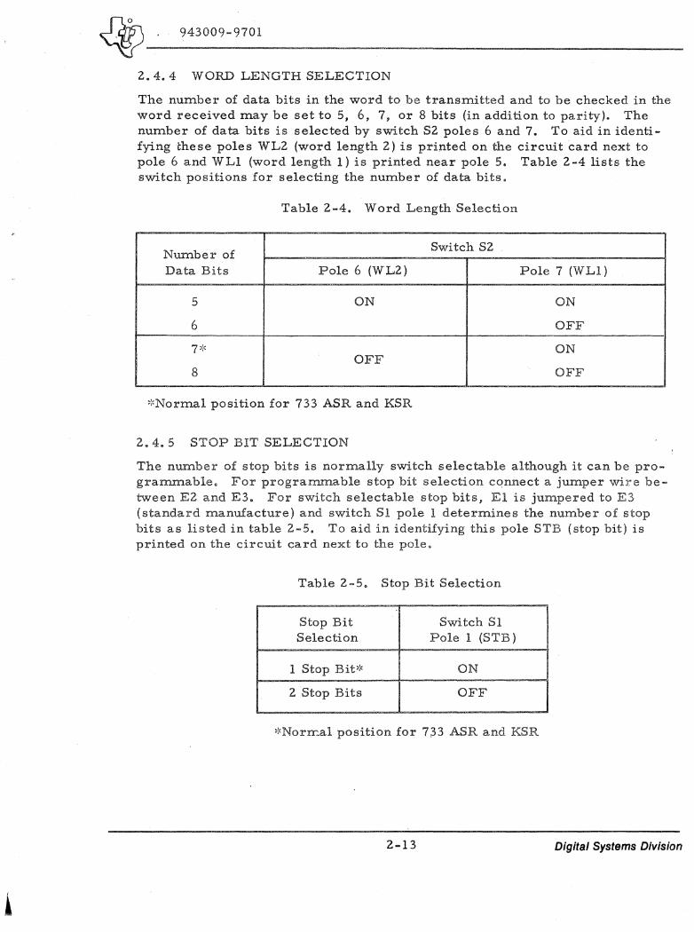
2.4.4 WORD LENGTH SELECTION
The number of data bits in the word to be transmitted and to be checked in the word received may be set to 5, 6, 7. or 8 bits (in addition to parity). The number of data bits is selected by switch S2 poles 6 and 7. To aid in identifying these poles WL2 (word length 2) is printed on the circuit card next to pole 6 and WLI (word length 1) is printed near pole 5. Table 2-4 lists the switch positions for selecting the number of data bits.
Table 2-4. Word Length Selection
Number of Switch S2
Data Bits Pole 6 (WL2) Pole 7 (WLl)
5 ON ON
6 OFF
7'" '" ON OFF
8 OFF
':'Normal position for 733 ASR and KSR
2.4. 5 STOP BIT SELECTION
The number of stop bits is normally switch selectable although it can be program..mable. For progranunable stop bit selection connect a jumper wire between E2 and E3. For switch selectable stop bits, El is j'l.lmpered to E3 (standard manufacture) and switch S1 pole 1 deterrnines the number of stop bits as listed in table 2-5. To aid in identifying this pole STB (stop bit) is printed on the circuit card nex.t to the pole.
Table 2-5. Stop Bit Selection
. Stop Bit Switch Sl Selection Pole 1 (STB)
1 Stop Bit':' ON
2 Stop Bits OFF
':'Norn:al position for 7.33 ASR and KSR
2-13 Digital Systems Division
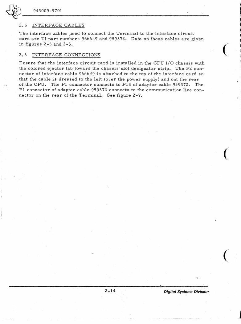
)217.5\, __ _ ~ 943009-9701 ---_. __ ._------------,-----,----------2.5 INTERFACE CABLES
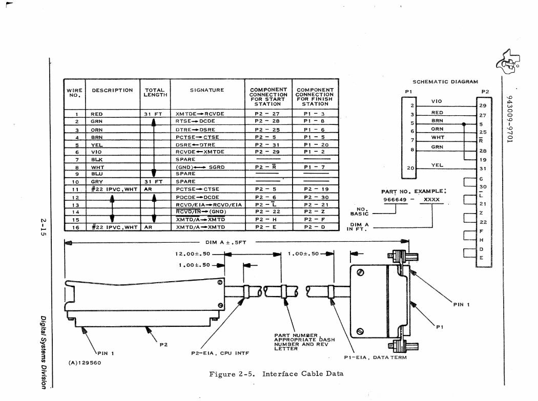
The interface cables ;used to connect the Terminal to the interface circuit card are TI part numbers 966649 and 959372. Data on these cables are given in figures 2-5 and 2-6.
2.6 INTERFACE CONNECTIONS
Ensure that the interface circuit card is installed in the CPU 1/0 chassis with the colored ejector tab toward the chas sis slot designator strip_ The P2 connector of interface cable 966649 is attached to the top of the interface card so that the cable is dressed to the left (over the power supply) and out the rear of the CPU. The PI connector connects to P13 of adapter cable 959372. The PI connector of adapter cable 959372 connects to the communication line connector on the rear of the Terminal. See figure 2-7.
'r
2-14 Digital Systems Division
(
(
(
,~ I
I
I r I
r-
N I I-'
In
I:) Q"
~ ~ CD ~ I:) :;,:" en 0-::3
WIRE DESCRiPTION TOTAL SIGNATURE COMPONENT COMPONENT NO. LENGTH CONNECTION CONNECTION
FOR START FOR FINISH STATION STATION
1 RED 31 FT XMTDE-RCVDE 1"2 - 27 PI - 3
2 GRN RTSE_DCDE 1"2 - 28 PI - 8
3 ORN DTRE-DSRE 1"2 - 25 PI - 6
4 SRN PCTSE-CTSE 1"2 - 5 PI - 5
5 YEL DSRE-OTRE 1"2 - 31 1"1 - 20
6 VIO RCVDE-XMTDE 1"2 - 29 1"1 - 2
7 BL.K SPARE
8 WHT (GND)- SGRD 1"2 - R PI - 7
9 BLU SPARE
10 GRY 31 FT SPARE
1 1 #22 IPVC. WHT AR PCTSE-CTSE 1"2 - 5 1"2 - 19
12 PDCDE-DCDE 1"2 - 6 1"2 - 30
13 RCVD/EIA-RCVD/EIA 1"2 -I:. 1"2 - 21
14 RCVD/IN- (GND) 1"2 22 1"2 - Z
15 1 1 XMTD/A_XMTD 1"2 - H 1"2 - F
16 Jt.22 IpVC, ..... _HT AR --
XMTD/A-XMTD 1"2 - E 1"2 - 0
r .. ooo±.5:':{05FT l 'oOO±.SOl t .OO±.50 r
~ =-- 0L ,..,. .... n • A ,...
PiN
(A)129560
1"2
P2-EIA, CPU INTF
PART NUMIiIER , APPROPRIATE DASH NUMBER AND REV LETTER
I
I
Figure 2-5. Interface Cable Data
NO. BASIC
DIM A IN FT"
r--o
1"1
Pl-EIA. DATA TERM
SCHEMATIC DIAGRAM
1"2
VIO r9 I ;:~_:7 n"" 11 25 t :.:::.
19
I .':L 131
PIN 1
6
30
L
21
Z
22
F
H
D
E
~ --.0 f!:>. VJ o o --.0 I
--.0 -l o I-'

1-
N I I-'
'"
I::) !C" ~~ -~ Cii ~ I::)
<" c;;" o· :;)
TOTAL WIRE OESCR I PT ION LENGTH NO.
1 #22 IPVC WHT
2
3
4
5
6
7
B
9 #22 JPVC WHT
P13
(A)129561
~
START FiNISH STATION STAt.TION SCHEMATIC DIAGRAM
P!3 PI t""""""'" ,...........
PI - A P13 - 1 I A
H J 2 2 H
10 3 3 10
C 4 4 C
8 5 5 8 9 6
7 7 6 9
, K B 7 7
PI - 6 P13 - 20 8 K
20 6
l......- i-
APPROPRIATE PART NO. AND REV LETTER
Figure 2-6. Adapter Cable Data
~
KEY SLOT NEAR SIDE
I~
~ -.D
*"" t.W o o -.D I
-.D -J o .....

~ ____ 9_4_3_0_0_9_-9_7_0_1 ______________________________________________ ___
733 ASR OR CPU 733 KSR
966637-0002 ":1"'"
COMMUN (CATION -,Pl P13 Pl-EIA 966649-0030 P2-EIA I I~ LINE INTERFACE CONNECTOR .....J 959372-2 DATA TERM CPUINTF I
....
(A)129562
Figure 2 -7. Interface Connectors
2 .. 17/2-18 Digital Systems Division

· ,J
(
,.
I'" !
(
(

~-------~ 943009-9701
3.1 GENERAL
SECTION III
OPERATION
This section contains a brief description of the controls and indicators of the Term.inals. More detailed information is contained in Electronic Data Terminals Manual, part number 959227-9701. Preliminary operation information is also given in this section.
3.2 TERMINAL CONTROLS AND INDICATORS
The Terrninal's primary control areas are:
1. The ON-LINE/OFF and master POWER switch
2. The keyboard controls
3. The upper switch panel (ASR only).
3.2.1 ON-LINE/OFF SWITCH (FIGURE 3-1)
In ON-LINE, the terminal is set up to communicate with external devices through the line interface. The terminal transmits to the outside line from the keyboard or playback tape and receives data on the printer or recorder tape.
3.2.1.1 ASR LOCAL OPERATION. Local operation for the ASR is normally controlled from the upper switch panel LINE/OFF /LOCAL switches (figure 3-2) while the terminal ON-LINE/OFF switch remains set to ONLINE. The ON-LINE/OFF switch is set to OFF if it is desired to disconnect the entire terminal from the communications line. When set to OFF, the printer and keyboard are automatically set to the local mode if the upper
(A)128600
ON
LINE
OFF
POWER
~ §
Figure 3-1. Terminal ON-LINE/OFF Switch and Power Switch
3-1 Digital Systems Division
~~-------~----------~ 943009-9701
switch panel PRINTER and KEYBOARD switches are set to either LINE or LOCAL. The playback and recorder, however, are held in the off state unless the bottom row LINE/OFF /LOCAL switches are set to LOCAL.
3.2.2 KEYBOARD CONTROLS
The standard USASCII keyboard special function keys are the following:
TAPE, TAPE
HERE IS
These two keys are used in the local mode to allow editing of data in the record buffer. After placing characters in the record buffer, tape reverse (T~E) backspaces a character at a time to the selected character, then the character can be changed from the keyboard. To return to the point where the tape was started, actuate tape forward (T~E) as many times as necessary. If the PRINTER switch is in LOCAL. the printhead will move with actuation of these switches to help locate the character. No code is transmitted.
Depressing this key activates the optional AnswerBack memory. However, this option is not standard for Terminals supplied with 980 Computers.
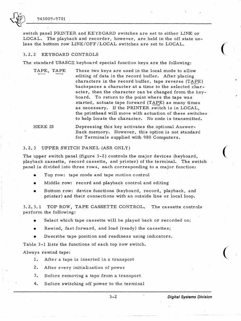
3.2.3 UPPER SWITCH PANEL (ASR ONLY)
The upper switch panel (figure 3-2) controls the major devices (keyboard, playback cassette, record cassette, and printer) of the terminal. The switch panel is divided into three rows, each corresponding to a major function:
• Top row: tape mode and tape motion control
• Middle row: record and playback control and editing
• Bottom row: device functions (keyboard, record, playback, and printer) and their connections with an outside line or local loop.
3.2.3.1 TOP ROW, TAPE CASSETTE CONTROL. The cassette controls perform the following:
• Select which tape cassette will be played back or recorded on;
• Rewind, fast forward, and load (ready) the cassettes;
• Describe tape position and readiness using indicators.
Table 3 -1 lists the functions of each top row switch.
Always rewind tape:
1. After a tape is inserted in a transport
2. After every initialization of power
3. Before removing a tape from. a transport
4. Before switching off power to the terminal
3-2 Digital Systems Division
(
(
(
~ ____ 9_4_3_0_0_9_-9_7_0_l ___________________________________________________ __
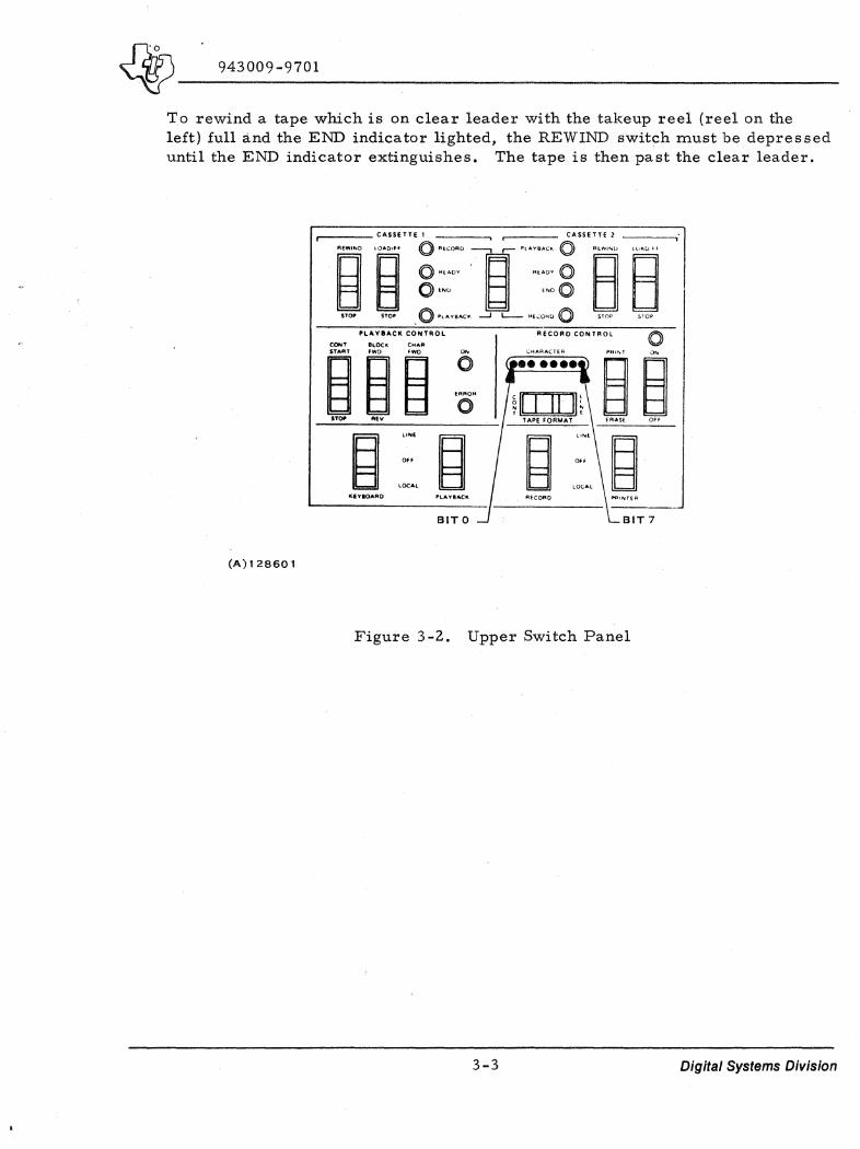
To rewind a tape which is on clear leader with the takeup reel (reel on the left) full and the END indicator lighted, the REWIND switch must be depressed until the END indicator extinguishes. The tape is then past the clear leader.
(A)12B601
CONT STA'"
'lA-YIIACK CONTROL
BLOCK CHAR FWD FWO
~~ •• v
~ LONE
Off
LOCAL
KEYIOARO PLAYBACk
BITO BIT 7
Figure 3 -2. Upper Switch Panel
3-3 Digital Systems Division

J}n5\, __ _ ~ 943009-9701 -----------------------------
r-r .....;..-- CAnUTE' __ --., • CAUUTE 2 __ ---, o A£COfitO P',-"VIACK 0 I"(WINO lOADffF
srop
o .,ADY "EAOV 0 B B o END END 0 o PU\YIACk: AE.CORO 0
(A)128602
Table 3-1. Tape Control Switches (Switch Panel Top Row)
Switch/Indicator Function
~-------------------------+------------------------------------------.--.~ REWIND /STOP
LOAD /FF ISTOP
REWIND causes the tape to wind toward thebeginning-of-tape; continues until clear leader is sensed or STOP is pressed
After rewinding to tape beginning, the cassette is "loaded II by pressing LOAD/FF. Tape moves forward to the beginning of tape marker, then stops. Pressing LOAD/ FF again causes the tape to wind forward at high speed to the end of tape or until STOP is depressed. The fast forward is useful in advancing the tape to the opposite end or for performing a local tape search for editing purposes.
NOTE
REWIND and LOAD /F;F are inoperative when RECORD CONTROL or PLAYBACK CONTROL (second row of switches) are ON.
PLAYBACK/RECORD Switch
PLAYBACK/RECORD INDICATOR Lamps
END Indicator Lamps
READy'Indicator Lamps
Selects which cassette is in playback mode or record mode (cassette 1 or 2); cassettes automatically switch to opposite modes.
Indicate cassette is ill playback or record mode.
Lights when clear leader is sensed at either end of tape
Lights when cassette is ready for applicable record or playback operation.
3-4 Digital Systems Division
(
',"
(
(

1
~ ____ 9_4_3_0_0_9_-9_7_0_1 ______________________________________________ __
3.2.3.2 MIDDLE ROW, PLAYBACK AND RECORD CONTROLS. Some of the functions performed by the PLAYBACK and RECORD controls are the following:
'. Allow print or erasure of blocks while recording;
• Start and stop tapes during recording or playback;
• Select whether recording will be either line or continuous tape format;
• Perform the edit functions. Editing is conducted in the LOCAL mode only (off-line).
Table 3-2 lists functions of each middle row switch.
PLAV8ACK CONTROL RECORD CONTROL 0 CooT ILOCK <MAR STAIIIT .... 'WD ON CH"AACTEA 'RINT ON
~ ~.~ 0 ( ........ )
~ ~ ERROR
~ iI I II II~ 0 sr"" ... TAPE FORMAT ERASE 0 ..
(A)128603
Table 3-2. PLAYBACK/RECORD Control Switches (Switch Panel Middle Row)
Switch/Indicator Mode Function
1----------+-----+-----PLA YBACK CONTROL ------of
CONT START/ STOP
BLOCK FWD/ REV
P L A Y B A C K
Momentarily pressing CONT,START begins continuous playback of the cassette designated by the illuminated PLAYBACK light. Tape will stop when clear leader is sensed or STOP is momentarily pres sed.
Momentarily pressing BLOCK FWD causes the next block on tape to be read and played back, or the remainder of a block should the playback of that block have been stopped in the middle. Momentarily pressing REV causes the tape to back up one block and stop (used in block locating).
3-5 Digital Systems Division

~ _____ 94_3_0_0_9_-_9_7_0_1 _____________________________ . __ . ___________________ ~--------------Table 3-2. PLAYBACK/RECORD Control Switches
(Switch Panel Middle Row) (Continued)
Switch/Indicator
CHAR FWD
ON Indicator Lamp
ERROR Indicator Lamp
Mode Function
Momentarily pres sing CHAR FWD allows reading out the playback buffer one character at a time. If the buffer is empty, the next block will be entered in the buffer from the tape, and the first character will be read. A character can be read on the CHARACTER display (if duplicating a tape) or on the printer.
Lights when PLAYBACK CONTROL is in use.
Lights when a parity error (missing flux reversal) on the tape is found during playback.
t-----------I-----t------RECORD CONTROL---·----4
CHARACTER Incator Lamps
LINE/CONT (TAPE FORMAT switch)
R E C o R D
Shows 7-bit USASCn code of the character being addressed in the Record Buffer. Bits 0 to 7 read from left to right. Bit 7 is used internally by the terminal.
This tWo-position switch controls the recording tape format. When the switch is in the LINE position, recording of data on tape is initiated by the USASCII carriage return character or the 86th character of each block. Therefore, each block of data normally corresponds to one line of printout on the printer. This format is especially helpful when preparing and/or editing a tape on the recorder. With TAPE FORMAT switch :j.n the continuous (CONT) position, recording of data on tape is initiated only by the 86th character of each block. Therefore, each block of data on tape may contain several lines of printout on the printer. This format is especially useful when maximum tape storage is desired. Tapes recorded in one format may be easily converted to the other format through the tape duplicating process.
3-6 Digital Systems Division
(
(
(
I I I I I I I
I I I
\ ,. I
!
! i
~ I I

~_· ___ 9_4_3_0_09_-_9_7_0_1 _____________________________________________ __
Table ~ ... 2. PLAYBACK/RECORD Control Switches (Switch Panel Middle Row) (Continued)
Switch/Indicator
PRINT /ERASE
ON/OFF
ON Indicator Lamp
Mode Function
This. switch is used to check record buffer contents during editing. The PRINTER and RECORD switches must be set to LOCAL. Contents of the record buffer will be printed out (but not recorded on tape) when PRINT is pressed and the buffer contents will not be affected. Pressing ERASE will erase the record buffer contents but will not affect data recorded oh the tape. To erase an entire tape cassette, refer to Electronic Data Terminals Manual, part number 959227-9701.
This switch turns on the recorder and RECORD CONTROL allowing receipt of data into the record buffer and transferring the contents of the record buffer (if any) to tape. 1£ ERASE is pressed before or during actuation of OFF and OFF is released first, tape erasure will be initiated and continue q.ntil OFF is pressed again.
Lights when RECORD CONTROL is in use.
3.2.3.3 BOTTOM ROW, DEVICE CONTROLS. The functions of the major 733 ASR devices are controlled by the bottom row of switches, as follows:
Select whether to connect the devices to the local loop or to the outside communication line (LINE, LOCAL);
Disconnect the devices from both the local loop and outside communication line (OFF).
3-7 Digital Systems Division
~ ____ 9_4_3_00_9_-_9_7_0_1 __________________ _ ----------------------~-----
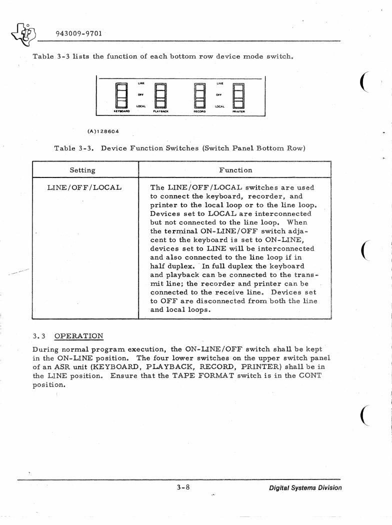
Table 3-3 lists the function of each bottorTl row device mode switch.
~ UN'
~ ~ 1.ItlIE
Of. Of'
LOeA' U')CAL
KIVIOARO "LAv,4C.: RfiCORO Pi'lINTEPI
(A)128604
Table 3-3. Device Function Switches (Switch Panel Bottom Row)
Setting Function
LINE/OFF/LOCAL
3.3 OPERATION
The LINE/OFF /LOCAL switches are used to connect the keyboard, recorder, and printer to the local loop or to the line loop. Devices set to LOCAL are interconnected but not connected to the line loop. When the terminal ON-LINE/OFF switch adjacent to the keyboard is set to ON-LINE, devices set to LINE will be interconnected and also connected to the line loop if in half duplex •. In full duplex the keyboard and playback can be connected to the transmit line; the recorder and printer can be connected to the receive line. Devices set to OFF are disconnected from both the line and local loops.
During normal program execution, the ON-LINE/OFF switch shall be kept in the ON-LINE position. The four lower switches on the upper switch panel of an ASR unit (KEYBOARD, PLAYBACK, RECORD, PRINTER) shall be in the LINE position. Ensure that the TAPE FORMAT switch is in the CONT position.
I·
3-8 Digital Systems Division
(
(
(

~ ____ 9_4_3_0_0_9_-_97_0_1 ______________________________________________ __
SECTION IV
INTERFACE DESCRIPTION
4.1 GENERAL
The Model 733 Terminals imerface with the Model 980 computer using a standard 30 foot cable. The Model 733 ASR normally operates at a 1200 baud rate to allow rapid data transfer both to and from the cassette tape units.
NOTE
Although the Model 733 ASR can receive data at a 1200 baud rate, the printer section of the Terminal can only print at a 300 baud rate.
The Model 733 KSR normally operates at a 300 baud rate since it cannot print more than 30 characters per second. With the exception of the 11 0 baud rate, the USASCn character will be represented throughout the interface as the 10-bit data pattern shown in figure 4-1 and will be serially transmitted between
MARKING ING -1- -, 1 -1- - r --T - -r-I ...... I I I I I I --.
m III I III I I III
.J I I I ! I ......
=i: I I\J
I Cr)
I '<t III I \0 I .....
l-I- =11= =11= =11= =11= =11= "'II:: I l- I- l- I- l- I- I- m I-m I I I I I I I-
m III m III III ·m III )0- m II:: 0« 0« 0« 0« ~ 0« 0« l- n. 0( l- I l- I l- I l- I I
l- I l- I II:: 0 I- <I: 0« 0( <I: 0( 0( 0( 0( I-III 0 0 0 c c c c n. III
SPACING _J __ I __ l 1 __ 1 __ 1 _ _ 1 __ __ J SPACING
-{ ~BIT TIME J CHARACTER LINE
TIME VERSUS BAUD RATE 300-BAUD 1200-BAUD
BIT TIME 3.33ms .833ms
CHARACTER TIME 33.3015 8,33ms
(A)129563
Figure 4-1. Bit and Character Time Definitions
.4-1 Digital Systems Division
Jd7)\ __ -----'---___ _ ~ 943009-9701
all interface components as a start bit, seven data bits with the least significant bit first, a parity bit, and a stop bit. The seven bits of data in conjunc-tion with the parity bit comprise the standard 8-bit USASCII character code (-which is either presented to or expected from the computer. The start and stop bits are meaningful only with respect to timing considerations on the in-terface itself.
4. 1. 1 COMMUNICATIONS MODULE
The communications module is a general purpose circuit card used to interface data terminals and communications lines. The logic circuitry on the card performs all of the functions required to serially transmit and receive data while supplying a variety of status indicators and control functions to the computer. The formats of the computer write commands are defined in paragraph 4.2. 1. The formats of the computer read commands are defined in paragraph 4.2.2.
The transmit and receive circuits on the communication module operate independently of one another (full-duplex mode of operation). Each circuit contains the devices to convert TTL logic levels into ErA voltage levels and the converse. All outgoing circuits on the communications module present two levels to the interface cabling and the associated data terminal. The positive level is defined as +8 ±3 volts in reference to the common signal ground and the negative level is defined as -8 ±3 volts. All incoming circuits recog- ( nize any voltage on the interface lines between +3 and +25 volts as the posi-tive level and any voltage between -3 to -25 volts as the negative level.
4.1.2 INTERFACE CABLE
The interface cable is comprised of two independent serial data transmission lines, several control and status lines, and a common signal ground. Data on the interface signal lines between the communications module and the Ter~ minal is given in figure 4-2. Each of these lines may exist in one of the two different states; however, each of these states has a different nomenclature depending on the specific type of signal and/ or condition which is under discussion. Table 4-1 cross-references the various nomenclatures with their equi valent interface states.
4.1.3 BAUD RATE
The Model 733 ASR is interfaced at a baud rate of 1200 in order to provide a maximum efficiency in handling cas sette tapes. The teleprinter portion of the Model 733 ASR is only capable of printing 30 characters per second When -data is received in the on-line mode of operation. Therefore, in order to ( maintain a synchronous operation it is necessary to create an effective 300- _ baud transmission rate consisting of an 8.33 millisecond character tirne fol-lowed by a 25.0 millisecond minimum delay time. On the communications rrlOdule this is accomplished by setting the WIUTE REQUEST DELAY (WRD) bit of the module control register prior to initiating transmission of an USASCII character data string.
4-2 Digital Systems Division

~ ____ 9_4_3_0_0_9_-_9_70_1 ________________________________________________ __
COMMUNICATIONS MODULE INTERFACE CABLE DATA TERMINAL
FUNCTION
transmitted data
request to send
data terminal ready
pseudo clear to send
clear to send
data set ready
pseudo data carrier
detect
data carrier detect
received data
protective ground
5 i gna 1 ground
speci a I purpose
jumper wi res
(A)129564
SIGNAL
XMTDE
RTSE
DTRE
PCTSE
CTSE
DSRE
PDCOE
DCDE
RCDVE
PG
SG
RCVD/EIA
RCVD/IN
RCVD/IN-
(GND)
XMTD/A-
XMTD
XMTD/A
XMTD
P2-27_10
P2-28-K P2-25_9
P2-5 --,--.8 P2-19..J
P2-31_6
P2-6 :J P2-30
P2-29--H
P2-A -A
P2-r -7
P2-1 :=:J P2-21
P2-22::=J P2-Z
P2-H ~ P2-F
P2-E ~ P2-D
SIGNAL
RCVDE
DCDE
DSRE
CTSE
DTRE
XMTDE
PG
SG
Figure 4-2. Interface Data
FUNCTION
received data
data carri er detect
data set ready
clear to send
data terminal ready
transmitted data
protective ground
signal ground
Table 4-1. Signal to Nomenclature Cross Reference
Applicable Signals Conditions or .Interface State s
EIA voltage levels Negative (-8±3 volts) Positive (+ 8±3 volts)
Binary logic states Logic one Logic zero
Control and status functions Off On
Data transfer signals Marking Spacing
4.2 SIGNAL DEFINITIONS
4.2.1 COMPUTER TO INTERFACE (FIGURE 4-3)
• CLEAR READ REQUEST (CRR)
A logic one in bit 0 will clear the module READ REQUEST (RREQ) flag and its associated interrupt if one should exist. A logic zero causes no action.
4-3 Digital Systems Division

~ ____ 9_4_3_0_0_9_-9_7_0_l ______________________________________________________ _
'. WRITE DATA READY (WDR)
A logic one in bit 1 will cause the communication nlOdule transmit buffer register to be loaded with the USASCII character in bits 8-15 of the WDS data word. At the appropriate time the communications module will transfer the character to the transmit (shift) register and initiate serial transmission to the data terminal. A logic zero causes no action.
• CLEAR NEW DATA SET STATUS (CNS)
A logic one in bit 2 will clear the communications module DATA SET STATUS (DSS) flag and its associated interrupt if one should exist. A logic zero causes no action •
. \It CLEAR WRITE REQUEST (CWR)
A logic one in bit 3 will clear the cornrn.unications module WRITE REQUEST JWREQ) flag and its associated interrupt if one should exist. A logic zero causes no action.
• Bits 4, 5, and 6 are not used.
• LOAD MODULE CONTROL (CON)
A logic one in bit 7 will cause the communication module control register to be loaded with bits 8 through "12 of the WDS data word.
(Bits 13, 14, and 15 are not used).
The functions served by bits 8 through 12 are explained in the following paragraphs. A logic zero causes no action.
Interrupt Enable (INT)
A logic one in bit 8 will enable the cornrn.unications module to issue an I/O bus interrupt upon the occurrence of a READ REQUEST (RREQ). a WRITE REQUEST (WREQ). and/or a NEW DATA SET STATUS (change in state of Data Set Ready), A logic zero inhibits the interrupt. The interrupt is reset by clearing (CRR, CWR. and/or CNS) all the conditions (RREQ. WREQ. and/or DSS) which are causing the interrupt.
Write .Request Delay (WRD)
A logic one in bit 9 will enable the cornrn.unications module to delay approximately 33 milliseconds after starting serial transmission of an USASCII character before issuing the WRITE REQUEST (WREQ).This delay option creates an effective 300-baud serial transmission rate when addressing the teleprinter section of the Terminal through a IlOO-baud interface. A logic zero inhibits the delay action and allows the WRITE REQUEST (WREQ) in its normal manner. i. e •• as soon as the module is ready to accept another USASCII character from the computer.
4-4 Digital Systems D;vls/on
(
(
(

J2rJ5\ _______ _ ~ 943009-9701
0 1 2
eRR WDR CNS
("')129565
Stop Bit Select (SBS)
Bit 10 is not used.
Data Terminal Ready (DTR)
A logic one in bit 11 will maintain the communications module DATA TERMlNAL READY (DTR) circuit in the ON condition. This circuit drives the DATA SET READY input line of the Terminal and, in effect, enables the transmit and receive capabilities of the Terminal. A logic zero maintains the DTR circuit in the OFF condition.
Request To Send (RTS)
A logic one in bit 12 will maintain the communications module REQUEST TO SEND (RTS) circuit in the ON condition. This circuit drives the DATA CARRIER DETECT input line of the Terminal and instructs the Terminal to accept the transmission of USASCII characters from the communications module. A logic zero maintains the RTS circuit in the OFF condition.
Bit 13 (Reverse Channel Transmit - RCT), bit 14, and bit 15 (Break - BRK) are not used.
B 9 10 11 12 13 14 15
r-- B B B B B B B B B 7 6 5 4 3 2 1 (MSB) (LSB)
WDR=1 D .... T .... CHARACTER
3 4 5 6 7
NOT NOT NOT
i-"" CWR USED USED USED CON
B 9 10 ; I 12 13 14 15
CON=1 ... (NT WRD SBS DTR RTS RCT NOT NOT (NOT (NOT USED USED USED) USED)
MODULE CONTROL
Figure 4-3. WDS Data Word Format
4-5 Digital Systems Division

~ 943009-9701
4.2.2 INTERFACE TO COMPUTER (FIGURE 4-4)
• READ REQUEST (RREQ)
0 ,I
RREQ WREQ
(A)I29966
A logic one in bit 0 indicates that a USASCII character has been received from the terminal and stored in the communications module receive buffer register and that the character appears as bits 8 through 15 of the RDS data word. If the communications module I/O bus interrupt has been previously enabled then the I/O bus interrupt will be maintained as long as the RREQ signal is true. The RREQ flag and its associated interrupt are reset by issuing a CLEAR READ REQUEST (CCR). A logic zero indicates that a character is not being held for transfer to the computer memory and that bits 8 through 15 contain the communications module. status information.
8 9 10 II 13' 14 111 .. B B B B B B B B
(MS\) 7 8 9 .. 3 ·2
(LSJ) RREQ.I
DATA CHARACTER
2 3 .. S 8 7 ';
OSS RFE RTE .RPE NOT NOT r-. USED USED ,
,
, B 9 10 II 12 13 I .. 111
RREQ=O ~ .XBL XRL NOT RING lCY llCD CTa DaR
USED JNOT NOT NOT (NOT • SED) SED) SED) USED)
MODULE STATUS
Figure 4-4. RDS Data Word Format
4-6 Digital Systems Division
(
(
(
... J

~ 943009-9701
• WRlTE REQUEST (WREQ)
A logic one in bit 1 indicates that the transmit buffer register is presently empty and ready to accept another USASCII character for serial transmission to the Terminal. If the communications module I/O interrupt has been previously enabled, then the I/O bus interrupt will be maintained as long as the WREQ signal is true. The WREQ flag and its associated interrupt are reset by issuing a CLEAR WRITE REQUEST (CWR). A logic zero in bit I indicates that the communications module is not presently requesting an additional USASCII character for transmission to the Terminal. This situation may appear under two circumstances:
1. When the transmit buffer register already contains a USASCII character as indicated by the presence of the TRANSMIT BUFFER REGISTER LOADED (XBL) Signal.
2. When, the transmit buffer register is empty following the transmission of the last USASCII character in a data string, i. e., a new USASCII character was not sent to the com;munications module after the last WRITE REQUEST (WREQ) flag was cleared.
• NEW DATA SET STATUS (DSS)
A logic one in bit 2 indicates that a change of state has occurred in the DATA SET READY (DSR) signal. This usually indicates that the keyboard ON-LINE/LOCAL switch of the Terminalhasbeen repositioned. If the communications module I/O interrupt has been previously enabled, then the I/O bus interrupt will be m~intained as long as the nss signal is true. The DSS flag and its associated interrupt are reset by issuing a CLEAR NEW DATA SET STATUS (CNS). A logic zero in bit 2 indicates that no change has occurred in the DATA SET READY (DSR) signal since the last CLEAR NEW DATA SET STATUS (CNS) was issued.
• READ FRAME ERROR (RFE)
A logic one in bit 3 indicates that improper character framing was detected by the receive circuitry. This error indicates either improper timing or erroneous stop bit(s) have been received. A logic zero indicates that no framing error is detected. This error status remains until a character with the proper framing is received or the module is reset. Bit 3 is valid only if bit 0 (RREQ) is a logic one.
• READ TIMING ERROR (R TE)
The READ TIMING ERROR (RTE) flag is only valid as long as the READ REQUEST (RREQ) signal of the interface is true. A logic one in bit 4 indicates that the communications module has received another USASCII character from the Terminal before the computer has
4-7 Digital Systems Division

~ ____ 9_4_3_0_0_9_-9_7~O_1 ____________ ~ ________________________________ __
completed storing the previous character. In this event, the module replaces the previous with the one most recently received and, as ( such, this flag indicates that one or more characters have been lost in transmission. The RTE flag is cleared when another character is properly received; provided, that a CLEAR READ REQUEST (CRR) has been previously issued. A logic zero indicates that no characters have been lost in transmission.
• READ PARITY ERROR (RPE)
The READ PARITY ERROR (RPE) flag is only valid as long as the READ REQUEST (RREQ) signal of the interface is true. A logic one in bit 5 indicates that improper parity was detected by the communications module receive circuitry. Both the corn.rn.unications module and the Terminal expect odd par~ty. This flag indicates that the received character contained even parity. The RPE flag is cleared when another character is properly received; provided that a CLEAR READ REQl,TEST (CRR) has been previously issued. A logic zero , indicates that the character was properly received with odd parity.
,
• Bits 6 and 7 are not used.
Transmit Buffer Register Load.ed (XBL)
A logic one in bit 8 indicates that the corn.rn.unications .module transmit buffer register is presently loaded with a USASCII character and is unable to accept another. A logic zero indicates that the USASCn character has been transferred to the transmit (shift) register and that the transmit huffer register is now ready to accept another USASCn character.
Transmit (Shift) Register Loaded (XRL)
A logic one in bit 9 indicates that the communications module transmit (shift) register is presently loaded with the last USASCn character supplied by the computer and that the character is in the process of being serially transmitted to the Terminal. A logic zero indicates that the module transmit (shift) register is empty and that no seri~l transmission is presently in progress.
Bit lOis not used.
Ring Indicator (RING)
Bit 11 is not used in this application and should always appear in the logic zero state.
4-8 Digital Systems Division
(
(

~_. ___ 9_4_3_0_0_9_-9_7_0_l ______________________________________________ ~
Reverse Channel Receive (RCV)
Bit 12 is not used in this application and should always appear in the logic zero state.
Data Carrier Detect (DCD)
Bit 13 is not used in this application and should always appear in the logic one state.
Clear to Send (CTS)
Bit 14 is not used in this application and should always appear in the logic one state.
Data Set Ready (DSR)
A logic one in bit 15 indicates that the Terminal is in the ONLINE mode of operation. This circuit is driven by the DATA TERMINAL READY output line of the Terminal and is maintained in the ON condition as long as the keyboard ON-LINE switch is engaged. A logic zero indicates that the Terminal is operating in the LOCAL mode.
A change of state in the DATA SET READY signal will cause the COrnn'lunications module to generate an I/O bus interrupt; provided that the interrupt has been previously enabled. This interrupt may be reset by issuing a CLEAR NEW DATA SET STATUS (CNS). However, the DATA SET READY (DSR) signal, will remain at its last logic level until another change of state occurs in the Terminal.
Note that the Model 733 ASR may have its keyboard ON-LINE/OFF. switch ON-LINE without any of the associated devices actually being on line. Therefore, it becomes necessary to perform a REQUEST STATUS function in order to determine which of the associated devices (PLAYBACK, RECORD, KEYBOARD and/or PRINTER) are actually ON-LINE.
4.3 REMOTE DEVICE CONTROL (ASR ONLY)
The Model 733 ASR data Terminal has the capability of accepting a wide variety of Remote Device Control (RDC) functions in the form of USASCn characters received over the interface lines. These control functions allow the computer to perform a multitude of operations including such mechanical tasks as rewinding and loading cassettes.
All of the RDC logic circuitry is located on a single circuit card located in slot number 6 of the KSR unit. A manually-operated ON-OFF switch, located on the top of the card and accessible through the sub-assembly cover, is provided to allow the operator to disable all of the RDC functions if desired.
4-9 Digital Systems Division
)}n~ ______ ---.--_ ~ 943009-9701
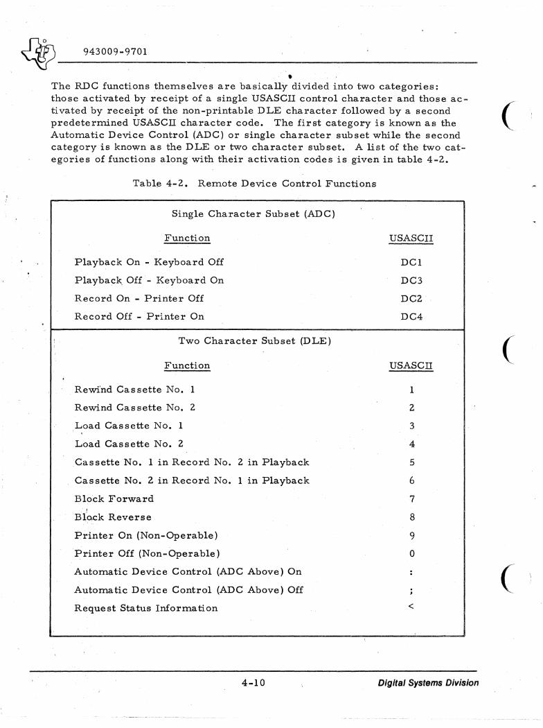
• The RDC functions theITlselves are basically divided into two categories: those activated by receipt of a single USASCII control character and those ac- (_ tivated by receipt of the non-printable DLE character followed by a second predeterITlined USASCIl character code. The first category is known as the AutoITlatic Device Control (ADC) or single character subset while the second category is known as the DLE or two character subset. A list of the two cat-egories of functions along with their activation codes is given in table 4-2.
Table 4-2. ReITlote Device Control Functions
Single Character Subset (ADC)
Function
Playback On - Keyboard Off
Playback Off - Keyboard On
Record On - Printer Off
Record Off - Printer On
Two Character Subset (DLE)
Function
Rewind Cassette No. 1
Rewind Cassette No. 2
Load Cassette No. 1
Load Cassette No. 2
Cassette No. 1 in Record No. 2 in Playback
Cassette No. 2 in Record No. I in Playback
Block Forward
Black Reverse
Printer On (Non-Operable)
Printer Off (Non-Operable)
AutoITlatic Device Control (ADC Above) On
AutoITlatic Device Control (ADC Above) Off
Request Status lruorITlation
4-10
USASCII
DCI
DC3
DC2
DC4
USASCIl
1
2
3
4
5
6
7
8
9
0
<
Digital Systems Division
(
(
~~------------------~ 943009-9701
Note that the RDC logic circuitry automatically disables the teleprinter portion of the Model 733 ASR from printing the first character received after the DLE character code. This ensures that all of the two character functions are, in effect, treated in the same manner as any non-printable USASCII control character such as those in the ADC category.
4.3.1 FUNCTIONAL DESCRIPTIONS
The following paragraphs are functional descriptions of each ADC character. Since most of these functions have self-explanatory names these descriptions are of their operation.
4. 3.1.1 SINGLE CHARACTER SUBSET (ADC)
• PLAYBACK ON-KEYBOARD OFF (DCl = 1116)
The "playback on" function initiates the reading and transmitting of characters from the cassette tape; provided the playback cassette is loaded and ready as indicated by bit number 1 of the Status Character (reference paragraph 4. 3, 1. 3). This function is performed only on data received over the communication lines or generated in the local loop.
• PLAYBACK OFF-KEYBOARD ON (DC3 = 1316)
The "playback off" function terminates the reading and transnritting of characters from the cassette tape under the condition that if the DC3 character itself exists on the playback tape, then one more character after the DC3 character will be played back before the cassette is actually turned off. This function is performed on both transmitted and received data as well as data generated in the local loop.
• RECORD ON-PRINTER OFF (DC2 =1216)
The "record on" function initiates the receipt and recording of characters on the cassette tape; provided the record cassette is loaded and ready as indicated by bit number 5 of the status character.
Upon receipt of the DC2 character, the record function is turned on and the printer enters a print cycle regardless of the fact that DC2 is a non-printable character. As such, the interface will be locked out for an additional three 1200-baud character times (approximately 30 milliseconds after receipt of the DC2 parity-bit) before the printer is actually turned off thus readying the interface for the receipt of the first character to be recorded on the casse~te. The DC2 character itself is neither entered into the hardware buffer nor recorded on the tape. This function is performed only on data received over the communication lines or generated in the local loop.
4-11 Digital Systems Division

4P 943009-9701
---------------------------~-----------------------------------------------------------
• RECORD OFF-PRINTER ON (DC4 = 1416)
The flrecord off" function terminates the receipt and recording of characters on the cas sette tape. Upon receipt of the DC4 character the record function is turned off and the printer is turned on. However, a print cycle is not entered as was the case with the DC2 function. The DC4 character is then entered into the hardware record buffer and all succeeding characters sent to the printer (including the DC2 character) are written into the same buffer location or floverpunchedfl. It is recommended that a RUBOUT (DEL) be sent following the DC4 to ensure that the overpunched character will not cause subsequent system problems.
Note that the contents of the record buffer are not automatically recorded on the cassette tape simply by the issuance of the flrecord offfl command. When recording in LINE tape format, a carriage return will ensure that the data is recorded on the cassette tape. When recording in CONT tape format, it is recommended to send at least 86 filler characters, usually (DEL) to the terminal after the last data entry and before the RECORD OFF command is transmitted.
4.3.1.2 TWO CHARACTER SUBSET (DLE)
• REWIND CASSETTE NO.1 (DLE, 1 = 1016, 3116)
Upon receipt of the rewind command and providing that the cassette tape is not already on clear leader at either end of the tape, cassette no. 1 will run in the reverse direction until clear leader is sensed at the beginning of the tape. From the time that the cassette begins performing the rewind operation, either bit number 1 or bit number 5 of the status character (depending on whether cas sette no. 1 is in the playback or record mode.! respectively) will be set to a logic zero indicating the cassette is not ready. When the re-wind operation has been completed then bit number 3 of the status character will become a logic one indicating the presence of the clear leader. Only the issuance of a LOAD CASSETTE no. 1 command will reset the appropriate bits of the status character and ready the cassette. If a rewind is is sued for cassette unit 1 and it is already on clear leader, the RDC is automatically disabled for 1.5 seconds.
NOTE
The cassette cannot be remotely rewound once it has entered the clear leader at the far end of the tape.
4-12 Digital Systems Division
(
(
(
I
1
~ 943009-9701
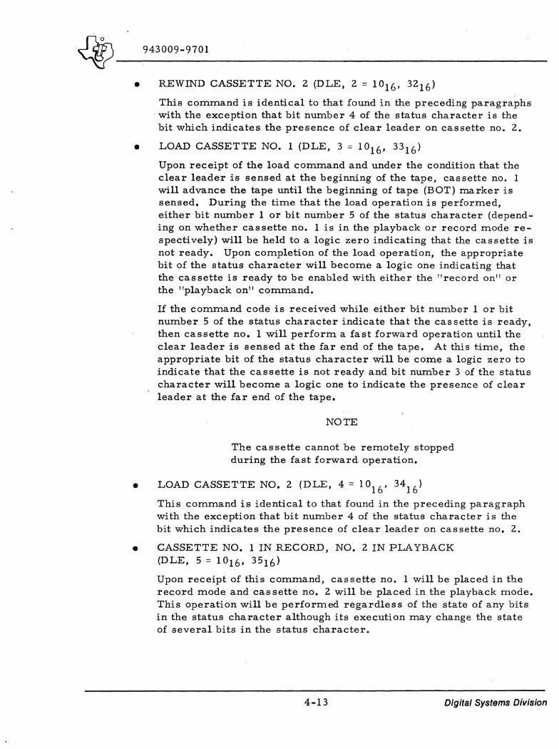
----------------------------------------------------------------------------• REWIND CASSETTE NO.2 (DLE, 2 = 1016, 3216)
This command is identical to that found in the preceding paragraphs with the exception that bit number 4 of the status character is the bit which indicates the presence of clear leader on cassette no. 2.
• LOAD CASSETTE NO.1 (DLE, 3 = 1016' 33 16)
Upon receipt of the load conunand and under the condition that the clear leader is sensed at the beginning of the tape, cassette no. 1 will advance the tape until the beginning of tape (BOT) marker is sensed. During the time that the load operation is performed, either bit num.ber 1 or bit number 5 of the status character (depending on whether cas sette no. 1 is in the playback or record mode respectively) will be held to a logic zero indicating that the cassette is not ready. Upon completion of the load operation, the appropriate bit of the status character will become a logic one indicating that the cassette is ready to be enabled with either the !!record on!! or the !!playback on!! command.
If the command code is received while either bit number 1 or bit number 5 of the status character indicate that the cassette is ready, then cassette no. 1 will perform a fast forward operation until the clear leader is sensed at the far end of the tape. At this time, the appropriate bit of the status character will be come a logic zero to indicate that the cassette is not ready and bit number 3 of the status character will become a logic one to indicate the presence of clear leader at the far end of the tape.
NOTE
The cassette cannot be remotely stopped during the fast forward operation.
• LOAD CASSETTE NO.2 (DLE, 4 = 1016' 3416 )
This conunand is identical to that found in the preceding paragraph with the exception that bit number 4 of the status character is the bit which indicates the presence of clear leader on cassette no. 2.
• CASSETTE NO. 1 IN RECORD, NO.2 IN PLAYBACK (D LE , 5 = 1 ° 16 , 3516 )
Upon receipt of this command, cassette no. 1 will be placed in the record mode and cas sette no. 2 will be placed in the playback mode. This operation will be performed regardless of the state of any bits in the status character although its execution may change the state of several bits in the status character.
4-13 Digital Systems Division

~o _ VI __ 943009-9701 ------------------------------------
• CASSETTE NO.2 IN RECORD, NO. 1 IN PLAYBACK (DLE, 6 = 1016. 36 16)
This command is similar to that which is found in the preceding paragraph with the exception that the result of this command is the complement of the result described in the preceding paragraph.
• BLOCK FORWARD (DLE, 7 = 1016, 3716)
Upon receipt of the block-forward cOmITland and under the condition that the playback ready bit of the status character is true, the cassette controller will read an 86 character block of data from the playback cassette and will initiate transmission of the resulting string of USASCII characters. Transmission of the string will continue until all 86 characters have been transmitted or until the playback-off (DC3) character is encountered in the transmission.
In the event: that the transmission is terminated by occurrence of the DC3 character on the tape, then the block forward command code may be reissued to initiate transmission of those characters remaining in the 86 character block of data originally read from the tape. The block forward command may have to be reissued a num-
-bel' of times depending on the number of DC3 characters in the original 86 character block of data.
In the event that transmission was never initiated because a playback error was discovered while reading the 86 character block from the cassette tape, then this function will cause the playback error bit of the status character (bit number 2) to be reset, the block containing the error to be bypassed, a new 86 character block to be read from the cassette tape, and finally, transmission of the new block to be initiated; provided the new block did not also contain a playback error.
• BLOCK REVERSE (DLE, 8 = 1°16. 3816)
•
Upon receipt of the block-reverse command and under the condition that the playback ready bit of the status character is true, the cassette controller will rewind the tape one full block of data (86 characters) and clear the contents of the hardware read buffer.
In the event that this command is received while the playback error bit of the status character (bit number 2) is true, then this function will also reset the error flag thereby preparing the block to be reread.
PRINTER-ON (DLE, 9 = 1016, 3916)
This command is non-operable since this function has already been automatically included as a part of the ADC RECORD OFF command (DC4).
4-14 Digital Systems Division
(
(
(

qp 943009-9701
-------------------------------------------------------------------------------------------
• Printer-OFF (DLE, ° = 1016' 3016)
This command is non-operable since this function has already been automatically included as a part of the ADC RECORD-ON command (DC2 ).
• AUTOMATIC DEVICE CONTROL ON (DLE, : = 1016, 3A16)
This command enables the playback on/off (DCI /DC3) and record onloff (DC2/DC4) functions to become effective after having been disabled with the ADC OFF command.
• AUTOMATIC DEVICE CONTROL OFF (DLE, ; ::: 1016, 3B16)
This command disables the playback on/off (DCl /DC3) and record on/off (DC2/DC4) functions. It is used when it is necessary to record the DCl through DC4 characters onto a cas sette tape without effecting the operation of the Terminal.
• REQUEST STATUS (DLE,<= 1016, 3C16)
Upon receipt of the request status command the Terminal will t~ansmit a specially configured USASCII status character to the computer interface. This character is used to determine when menchanical functions such as rewind and load operations are completed. It also indicates other data as described in the following paragraphs.
4.3.1.3 STATUS CHARACTER
The following paragraphs describe the USASCII status character transmitted by the Terminal in response to the RDC request status command. The bit positions within the character are defined .as shown in figure 4-5.
BIT NUMBER
(A)129567
BIAS 1
7
PRNTR RCRO BOE02 BOEOt PLYBK PLYBK ROY ROY ERR ROY
6 5 4 3 2
Figure 4-5. Status Character Bit Definition
4-15 Digital Systems Division

~- 943009-9701 ----------------------
• PLYBK RDY (Bit Number 1) (LSB)
A logic one level in this bit position indicates that the playback cas-sette is ready to be enabled with the ADC playback on (DCI) function (--or the RDC block forward (DLE , 7) function. If a logic zero level is in this bit position, then one or more of the following conditions must exist:
Cassette door open or cassette not in place
Cassette tape on clear leader
Playback not in line mode
Rewind or load operation still in execution.
• PLYBK ERR (Bit Number 2)
•
A logic one level in this bit position indicates that a playback error was discovered while an 86 character block of data was being read from the cassette tape. The transmission of any characters from that block of data is inhibited until the error status is reset to a logic zero level.
The RDC block forward and block reverse commands are normally used in the recovery of a playback error. -Both of these functions are capable of clearingthe error status.
BOE01 (Bit Number 3)
A logic one level in this bit position indicates that cassette no. 1 is positioned on clear leader at either the beginning or the end of the tape.
• BOE02 (Bit Number 4)
The description of this bit position is identical to that which is found in the preceding paragraph with the ex ception that the information is for cassette no. 2.
• RCRD RDY (Bit Number 5)
A logic one level in this bit position indicates that the record cassette is ready to be enabled with the ADC record on (DC2) function. If a logic zero level is in this bit position then one or more of the following conditions must exist.
Cassette door open or cassette not in place
Cassette tape on clear leader
Record not in line mode
Rewind on load operation still in execution
Record enable tab removed.
4-16 Digital Systems Division
(
(

~ 943009-9701
.. PRNTR RDY (Bit Number 6)
A logic one level in this bit position indicates that the teleprinter is enabled and ready for normal operation. 1£ a logic zero is in this bit position then one or more of the following conditions must exist:
Printer not in line mode.
Printer is disabled as a result of the ADC record-on function (DC2)
" BIAS Ill" (Bit Number 7)
This bit positionwill always be held to a logic one level to ensure that the status character is not an element of the USASCII control character subset.
4. 4 INTERFACE OPERATION
The following paragraphs describe the data transfer within the interface.
4.4. 1 COMPUTER TO TERMINAL
The following is a' description of the sequence of events which occur during the transmission of a USASCII data string to the Terminal and is directly applicable to the byte-by-byte transmis sion of any software character when addressing either the 300-baud teleprinter or the l200-baud cassette controller. However, when utilizing the 1200-baud interface to address the 300-baud teleprinter it is necessary to precede the transmission of the data string with a WDS instruction which sets the WRITE REQUEST DELAY (WRD) bit of the module control register true. This operation enables the module to provide approximately 33 milliseconds of delay between the time that the TRANSMIT. BUFFER LOADED (XBL) signal goes false and the time that the WRITE REQUEST (WRQ) signal comes true. In effect the WRITE REQUEST DELAY (WRD) option uses the l200-baud hardware interface to create an effective 300-baud transmission rate.
It is as sumed that the interface has been previously initialized by setting both the DATA TERMINAL READY (DTR) and the REQUEST TO SEND (RTS) lines of interface to their true state (logic one level).
An 8-bit character is sent out to the communications module by using a WDS instruction with the WRITE DATA READY (WDR) bit of the WDS data word set true. The communications module immediately loads the USASCII character into the transmit buffer register and the TRANSMIT BUFFER LOADED (XBL) signal of the interface comes true. If the communications module is presently in the process of transmitting a previous character, then the transmit (shift) register will not be empty and the TRANSMIT REGISTER LOADED (XRL) signal of the interface will be true. When transmission of the previous character is completed, then the transmit (shift) register becomes empty and
4-17 Digital Systems Division
~ _____ 94_3_0_0_9_-_97_0_l __________________________________ ~ __________ ~
the TRANSMIT REGISTER LOADED (XRL) signal of the interface goes false. The transmit buffer register will now transfer the new USASCII character to the transmit (shift) register and the TRANSMIT BUFFER LOADED (XBL) signal of the interface goes false while the TRANSMIT REGISTER LOADED (XRL) signal again comes true. If the module interrupt capability has been ( previously enabled, then the WRITE REQUEST signal will be accompanied by an I/O bus interrupt. At this point, a CLEAR WRITE REQUEST (CRR) is then issued thereby resetting the WRITE REQUEST (WREQ) signal to its logic zero level and additionally clearing the interrupt; provided no other in-terrupt conditions exist (READ REQUEST) true or change in state of DATA SET READY). The interface should now be reset 'and ready to accept another eight bit USASCII character from the computer.
4.4.2 TERMINAL TO COMPUTER
The following is a discussion of the sequence of events that occur during the reception of a USASCII data string from the Terminal and is directly applicable to the byte-by-byte reception of any USASCII character string regardless of the baud rate used. It is assumed that the interface has been previously initiali'zed by ensuring that the DATA SET READY line of the interface is in its true state (logic one level).
The communications module continually monitors the incoming signal lines which are normally in the marking (negative voltage) state. Whenthese lines become positive (spacing condition) the interface accepts this as the start-bit of a sequential lO-bit USASCII character code transmission. The next eight bits are brought into a receiving shift register and upon reception of the stop bit (tenth bit) the received USASCII character code is transferred to an 8-bit buf~erregister and the READ REQUEST (RREQ) signal of the interface comes, true~ If the module interrupt capability has been previously enabled, then the READ REQUEST signal will be accompanied by an I/O bus interrupt.
At this point the received USASCII character is normally stored into a prespecified memory location by using the appropriate RDS instruction. Finally. a CLEAR READ REQUEST (CRR) is then issued thereby resetting the READ REQUEST (RREQ) signal to its logic zero level and additionally clearing the interrupt; provided, that no other interrupt conditions exist (WRITE REQUEST true or change in state of DATA SET READY). The interface should now be reset to its original state thereby preparing it to receive another character from the Terminal.
In the event that the character was transmitted at an improper baud rate or with an erroneous number of stop bits, then the READ FRAMING ERROR (RFE) signal of the interface will come true.
4-18 Digital Systems Division
(
(

~ ____ 9_4_3_0_0_9_-_9_7_0l ________________________________________________ __
NOTE
The RFE flag is valid only as long as the READ REQUEST (RREQ) signal of the interface is also true. The READ FRAMING ERROR (RFE) signal is reset when another character is properly recei ved; provided a CLEAR READ REQUEST (CRR) has been previously issued.
In the event that another character is received by the interface before the computer has stored an already present character (i. e., if the READ REQUEST (RREQ) line is still true at the time another character is received), then the previous character is replaced by the one most recently received, and the READ TIMING ERROR (RTE) signal of the interface comes true. The presence of the R TE flag implies that one or more characters may have been lost in transmission.
NOTE
The RTE flag is only valid as long as the READ REQUEST (RREQ) signal of the interface is also true. The READ TIMING ERROR (RTE) signal is reset when another character is properly received; provided a CLEAR READ REQUEST (CRR) has been previously issued.
In the event that the character was received with an e.rroneous parity bit, then the READ PARITY ERROR (RPE) signal of the interface will come true.
NOTE
The RPE flag is only valid as long as the READ REQUEST (RREQ) signal of the interface is also true. The READ PARITY ERROR (RPE) signal is reset when another character is properly received; provided a CLEAR READ REQUEST (CRR) has been previously issued.
4-19/4-20 Digital Systems Division

(:
, "
(
(.

L
~ ____ 9_4_3_0_0_9_-_9_7_01 ______________________________ ~ ________________ ___
SECTION V
PROGRAMMING REQUIREMENTS
Programming requirements and examples are provided in Model 980 Computer Input/Output Manual, Part Number 961961-9734.
5-1/5-2 Digital Systems Division

(! I
(
(
.. J
~ ____ 94_30_0_9-_97_01 _________________________________ \_~~~~~ ______
ALPHABETICAL INDEX
Digital Systems Division
.' .
~. 943009-9701
ALPHABETICAL INDEX
INTRODUCTION
The following index liSts key words and concepts from the subject material of the manual together with the area(s) in the manual that supply mitior coverage of the listed concept. The numbers along the right side of the listing reference the following manual areas:
• Sections - References to Sections of the qtanual appear as "Section x" with the symbol x representing any numeric quantity.
• Appendixes - References to Appendixes of the manual appear as "Appendix y" with the symbol y representing any capital letter.
• Paragraphs - References to paragraphs of the manual appel!r as a series of alphanumeric or numeric characters punctuated with decimal points. Only the first character of the string may be a letter; all subsequent characters are numbers. The first character refers to the section' or appendix of the manual in which the paragraph is found.
• Tables - References to tables in the manual are represented by the capital letter T followed immediately by another alphanumeric character (representing the section or appendix of the manual containing the table). The second character is followed by a dash (-) and a number:
Tx,:"yy
• Figures - References to figures in the manual are represented by the capital letter F followed immediately by another alphanumeric character (representing the section or appendix of the manual containing the figure). The second character is followed by a dash (-) and a number:
Fx-yy
• Other entries in the Index - References to other entries in the index are preceded by the word "See" followed by the referenced entry.
t·
Index-! Digital Systems Division

~ 943009-9701 ----Adapter Cable Data .F2·6 BOE02 Bit .43.13 ADC Automatic Device Control Functions · 4.3 BOT Beginning of Tape (Load Cassette) .4.3.1.2 ADC Single Character Subset .4.3.1.1 Bottom Row, Device Controls .3.2.3.3 Address Selection, Module .2.4.1, T2·1
( ASR: Cable Data, Adapter .F2·6 Cassette Installation .2.2.2, F2·3 Cable, Interface .2.5,4.1.2, F2-5 Data Terminal Outline Dimensions .F2·1 Cassette: Local Operation .3.2.1.1 Controls, Top Row, Tape .3.2.3.1 Model 733 · 2.2 Installation ASR .2.2.2, Fl·] Paper Loading .2.2.1, F2·2 No.2 in Record, No. 1
ASR/KSR Data Terminal, Model 733 .FI·I in Playback .4.3.1.2 Automatic Device Control No.2 in Record, No.2
Functions .4.3,4.3.1.2 in Playback .4.3.L2 CCR Clear Read Request Command 4.2.2
Baud Rate .4.1.3, 4.4.1 Character Bit Definition, Status . . .F4·5 ASR · 4.1 Character Time Definitions, Bit .F4·1 Duplication .1.2.6.2 Character, Status .43.1.3 KSR · 4.1 Circuit Card, Interface . 2.4 Playback .1.2.6.2 Clear New Data Set Status Bit, CNS 4.2.1 Record .1.2.6.1 Clear Read Request Command, CCR 4.2.2 Selection .2.4.2, T2·2 Clear Read Request CRR Bit 4.2.1
Beginning of Tape (Load Cassette), BOT .4.3.1.2 Clear Read Request, CRR 4.4.2 Bias "I" Bit 04.3.1.3 Clear to Send Bit, CTS 4.2.2 Bit and Character Time Defmitions .F4·1 Clear Write Request Bit, CWR 4.2.1 Bit Definition, Status Character .F4·5 Clear Write Request Command, CWR 4.2.2 Bit Selection, Stop .204.5, T2·5 CNS Clear New Data Set Status Bit 4.2.1 Bit: Commands:
BOEOI 04.3.1.3 CCR Clear Read Request . 4.2.2 BOE02 04.3.1.3 CWR Clear Write Request 4.2.2 Clear Read Request CRR 4.2.1 Load Cassette No.1 .4.3.1.2 CNS Clear New Data Set Status 4.2.1 Load Cassette No.2 .4.3.1.2 ( CON Load Module Control 4.2.1 Rewind Cassette No. I .4.3 .1.2 CTS Clear to Send 4.2.2 Rewind Cassette No.2 .4.3.1.2 CWR Clear Write Request 4.2.1 Communication Line Interface 1.2.3 DCD Data Carrier Detect 4.2.2 Communications Module 2.4, 4.1.1 DSR Data Set Ready ., 4.2.2 Computer to Interface 4.2.1 DSS' New Data Set Status 4.2.2 Computer to Terminal Interface 4.4.1 OTR Data Terminal Ready 4.2.1 CON Load Module Control Bit 4.2.1 INT Interrupt Enable 4.2.1 Connections, Interface .2.6, Fl·? PLYBK ERR .4.3.1.3 Control Functions, Remote Device ,.14·2 PLYBK RDY .4.3.1.3 Control Switches: PRNTR RDY .4.3.1.3 Switch Panel Bottom Row, RCRD RDY .4.3.1.3 Device Function .3.2.3.3 RCT Reverse Channel Transmit 4.2.1 Switch Panel Middle Row, RCV Reverse Channel Receive 4.2.2 Playback/Record .13-2 RFE Read Frame Error 4.2.2 Switch Panel Top Row, Tape .1'3-1 RREQ Read Request 4.2.2 Controls: RTE Read Timing Error 4.2.2 Bottom Row, Device .3.2.3 .3 RTS Request to Send 4.2.1 Here is 3.2.2 SBS Stop Bit Select 4.2.1 Keyboard 3.2.2 STS Stop 2.4.5 Line/Local .3.2.3.3 WDR Write Data Ready . 4.2.1 Middle Row, Playback and Record .3.:U.2 WRD Write Request Delay . 4.1.3, Playback 3.:203.2
4.2.1, 4.4.1 Record .3.2.3.2 WREQ Write Request 4.2.2 Tape 3.2.2
\ XBL Transmit Buffer Register Terminal . 3.2
( Loaded 4.2.2 Top l{ow, Tape Cassette . . . . . . .3..2.3 J XRL Transmit (Shift) Register Cross Reference, Signal to Nomenclature .T4·1
Loaded 4.2.2 CRR Clear Read Request Bit , .4.2.1, 4.4.2 Block: CCR Clear Read Request Command 4.2.2
Forward DLE .4.3.1.2 CTS Clear to Send Bit 4.2.2 Reverse, DLE .4.3.1.2 CWR Clear Write Request Bit 4.2.1
BOEOI Bit .4.3.1.3 CWR Clear Write Request Command 4.2.2
---------------------------------------------------------------Index-2 Digital Systems Division

~ _____ 94_30_0_9-_9_70_1 __________________________________ ~~ __ -,-______ _
",1'
Data Carrier Detect Bit, DCD Data Format and Transmission Data Set Ready Bit, DSR Data Set Ready Signal, DSR Data Set Status Flag, DSS Data Terminal:
Model 733 ASR/KSR . . . . Outline Dimensions and Weight,
Model 733 ASR ..... Outline Dimensions and Weight,
Model 733 KSR Ready Bit ..... Ready Signal . . . .
Data Word Format, RDS Data Word Format, WDS Data, Adapter Cable . . . DCD Data Carrier Detect Bit Definition:
Bit and Character Time . Signal . . . . . . . . . Status Character Bit . . . . .
Delete, WRQ Write Request Signal Description:
Functional . . . General General, Interface Interface . . , . . . . .
Device Controls, Bottom Row . Device Function Switches (Switch
Panel Bottom Row) . . . . . Dimensions and Weight Model 733:
ASR Data Terminal . . KSR Data Terminal . . .
DSR Data Set Ready Bit . . DSR Data Set Ready Signal DSS Data Set Status Flag . DSS New Data Set Status Bit DTR Data Terminal Ready Bit DTR Data Terminal Ready Signal Duplication Baud Rate . . . . .
Flag: DSS Data Set Status RPE Read Parity Error RREQ Read Request RTE Read Timing Error WREQ Write Request ..
Format and Transmission, Data Format RDS Data Word . . . Format WDS Data Word ... Function Switches (Switch Panel
Bottom Row), Device . . . . Functional Descriptions Functions:
ADC Automatic Device Control Playback Off-Keyboard On . Playback On·Keyboard Off . RDC Remote Device Control Record Off-Printer On Record On-Printer Off
Here is Controls
4.2.2 1.2.1 4.2.2 4.2.2 4.2.1
. FI-l
.F2-l
.F24 4.2.1 4.4.1 .F44 .F4-3 .F2-6 4.2.2
.F4-1
. 4.2
.F4-5 4.4.1
4.3.1 .1.1
... 4.1 Section 4
.3.2.3.3
.T3-3
.F2·l
.F24 4.2.2 4.2.2 4.2.1 4.2.2 4.2.1
· 4.4.1 .1.2.6.2
4.2.1 4.2.2 4.2.1 4.2.2 4.2.1 1.2.1 .F44 .F4·3
.T3-3 4.3.1
· . 4.3 04.3.1.1
. .4.3.1.1
.4.3, T4-2 . 4.3.1.1 .4.3.1 J
· 3.2.2
Index-3
,.,,, Indicators, Terminal Controls an!,!::', Installa tion : '
ASR, Cassette General
Instruction: RDS WDS .....
INT Interrupt Enable Bit Interface:
· .. 3.2
.2.2.2, F2-3 · 2.1
2.4.1 2.4.1 4.2.1
Cable ...... . Circuit Card Communication Line
_ .. 2.5,4.1.2, F2-5
Computer ..... Computer to Terminal Connections Description Operation .
Interrupt Enable Bit, INT
Keyboard Controls Keyboard Switches KSR:
Baud-Rate ..... Data Terminal Outline Dimensions
and Weight, Model 733 ... Model 733 . . . . .--:. . . . Pa~er Loading ....... .
· ... 2.4 · . . . 1.2.3 · .4.2.1,4.2.2 · ... 4.4.1 · . .2.6, F2-7 Section 14, 4.1
· 4.4 4.2.1
3.2.2 3.2.1
· 4.1
.F2-4 · 2.3 2.3.1
Line Interface, Communication -~ . Line/Local Controls . . . . . Line/Off/Local Switches . . .
. 1.2.3
.3 .2.3.3
.3.2.1.1
.4.3.1.2
.4.3.1.2 Load Cassette No. 1 Commands Load Cassette No.2 Commands Load Module Control Bit, CON Loading ASR, Paper . . . Loading KSR, Paper . . . Local Operation, ASR . .
Middle Row, Playback and Record Controls
Model 733: ASR ..... ASR Data Terminal Outline
Dimensions and Weight ASR/KSR Data Terminal KSR ........ . KSR Data Terminal Outline
Dimensions and Weight Module Address Selection Module Parity Selection Module, Communications
New Data Set Status Bit, DSS .. Nomenclature Cross Reference, Signal
On-Line/Off Switch . . . Power Switch, Terminal
Operation ...... . ASR Local ..... . Interface . ... . . . . . . .
Option, WRD Write Request Delay
· .. 4.2.1 .2.2.1, F2-2
. 2.3.1
.3.2.1.1
.3.2.3 .2
· 2.2
.F2-l
.Fl-I · 2.3
· ... F24 .2.4.1, T2-1
· .. T2-3 2.4, 4.1.1
· . 4.2.2 · .. T4-l
.3.2.1,3.2.1.1 · . . .. F3-l Section 3, 3.3
.3.2.1.1 · .... 4.4 · ... 4.4.1
Digital Systems Division

~-----'------~ 943009-9701
Outline Dimensions and Weight, Model 733 ASR Data Terminal .F2·1
Outline Dimensions and Weight, Model 733 KSR Data Terminal .F24
Panel (ASR Only), Upper Switch Panel, Upper Switch Paper Loading:
ASR KSR
Parity Enable and Selection Parity Error Flag, RPE Read Parity Selection, Module Physical Specifications Playback
Baud Rate Controls Off·Keyboard On Functions On·Keyboard Off Functions Record Controls Tape Transport
PL YBK ERR Bit PL YBK RDY Bit Power Requirements . . .. .. Power Switch, Terminal On·Line/Off
Switch Printer
Off On Specifications Switches
, Programming Requirements
RCT Reverse Channel Transmit Bit RCV Reverse Channel Receive Bit
3.2.3 .F3·2
.2.2.1, F2·2 2.3.1 2.4.3 4.2.2 .12·3" 1.2.4
. 3.2.3.2, T3·2 .1.2.6.2 .3.2.3.2 .4.3.1.1 .4.3.1.1
.3.2.3.2, T3·2 .1.2.6.2 .4.3.1.3 .4.3.1.3
1.2.5
.F3·1 1.2.2
.4.3.1.2
.4.3.1.2 .Tl·1 3.2.1
Section 5
RDC Remote Device Control Functions RDS Data Word Format
4.2.1 4.2.2 · 4.3 .F44 2.4.1 RDS Instruction
Read Frame Error Bit, RFE Read Parity Error Flag, RPE Read Request:
Bit Flag Signal
Read Timing Error Bit, RTE Record Baud Rate Record Controls Record Off·Printer On Functions Record On·Printer Off Functions Record Tape Transport Remote Device Control:
ASR Only Functions Functions, ROC
Request Status, DLE Request to Send Request to Send Bit Requirements:
Power Programming
Reverse Channel Receive Bit, RCV Reverse Channel Transmit Bit, RCT Rewind Cassette No. 1 Commands
.4.2.2, 4.4.2
.4.2.2,4.4.2
4.2.2 4.2.1
.4.2.2, 4.4.2
.4.2.2, 4.4.2 .1.2.6.1 .3.2.3.2 .4.3.1.1 .4.3.1.1 .1.2.6.1
· 4.3 .T4·2 · 4.3
.4.3.1.2 4.4.1 4.2.1
1.2.5 Section 5
4.2.2 4.2.1
.4.3.1.2
Index-4
Rewind Cassette No.2 Commands RFE Read Frame Error Bit RPE Read Parity Error Flag RREQ Read Request Bit RTE Read Timing Error Bit RTS Request to Send Bit
SBS Stop Bit Select Bit Selection:
Baud Rate Module Parity Parity Enable Stop Bit Word Length
Signal Definitions Signal to Nomenclature Cross Reference Signal:
RFE Read Framing Error RPE Read Parity. Error RREQ Read Request RTE Read Timing Error WREQ Write Request XBL Transmit Buffer Loaded
'XRL Transmit Register Loaded Single.Character Subset, ADC Specifications
Physical Printer Tape Transport
Status Character Bit Definition USASCII
,STB Stop Bit Stop Bit Select Bit, SBS Stop Bit Selection Subset:
ADC Single·Character Two·Character
Switches: Keyboard Line/Off/Local On-Line/Off Printer (Switch Panel Bottom Row),
¥ Device Function .... (Switch Panel Middle Row),
Playback/Record Control (Switch Panel Top Row),
Tape Control . .
Tape: Cassette Controls, Top Row Control Switches (Switch Panel
Top Row) Controls Transport Transport Playback Transport Record Transport Specifications
Terminal: Controls and Indicators Interface, Computer to
.4.3.1.2 .4.2.2,4.4.2 .4.2.2,4.4.2 .4.2.1, 4.2.2 .4.2.2,4.4.2 .4.2.1, 4.4.1
4.2.1
.2.4.2, T2·2 .T2-3 2.4.3
.2.4.5, T2-5
. 2.4.4, T2-4 . 4.2 .T4-1
4.4.2 4.4.2
.4.2.2,4.4.2 4.4.2 4.4.1 4.4.1 4.4.1
.4.3.1.1 1.2
1.2.4 .Tl·l .Tl·2
.4.3.1.3 .F4-5
.4.3.1.3 2.4.5 4.2.1
.2.4.5, T2-5
.4.3.1.1
.4.3.1.2
3.2.1 .3.2.1.1 .3 .2.1.1
3.2.1
.T3-3
.T3-2
.T3-l
.3.2.3.1
.T3-l 3.2.2 1.2.6
.1.2.6.2
.1.2.6.1 .Tl-2
. 3.2 4.4.1
Digital Systems Division .
(
(
(

~ ____ 9_4_30_0_9_-9_7_0_1 ______________________ -'~r-______________________ _
Terminal: Model 733 ASR/KSR Data On-Line/Off Switch and
Power Switch Time Defillitions, Bit and Character Transmission Data Format Transmit (Shift) Register Loaded Bit,
XRL ......... . Transmit Buffer Loaded Signal,
XBL ......... . Transport Specifications, Tape Transport:
Playback Tape Record Tape . . . Tape ..... .
Two-Character Subset
Upper Switch Panel . . . . . Upper Switch Panel (ASR Only) USASCII Status-Character
WDR Write Data Ready Bit 4.2.1 .FI-l WDS Data Word Format .2.4.1, F4-3
Weight, Model 733 ASR Data Terminal .F3-1 Outline Dimensions and .F2-1 .F4·1 Weight, Model 733 KSR Data Terminal 1.2.1 Outline Dimensions and .F2-4
WLl Word Length 1 2.4.4 .4.2.2, 4.4.1 WL2 Word Length 2 2.4.4
Word Format: .4.4.l, 4.2.2 RDS Data .F4-4
.Tl-2 WDS Data .F4·3 Word Length Selection .2.4.4, T2-4
.1.2.6.2 WRD Write Request Delay Bit . 4.1.3,
.1.2.6.1 4.2.1, 4.4.1 1.2.6 WREQ Write Request Bit .4.2.1, 4.2.2, 4.4.1
.4.3.l.2 Write Data Ready Bit, WDR 4.2.l WRQ Write Request Signal Delete 4.4.1
.F3·2 3.2.3
.4.3.1.3 XBL Transmit Buffer Loaded Signal XRL Transmit (Shift) Register
.4.4.l,4.2.2
Loaded Bit .4.2.2,4.4.1
Index-S/Index-6 Digital Systems Division

(
(
(
L
USER'S RESPONSE SHEET
Manual Title: Model 980 Computer Terminal User's Guide
Model 733 ASR/KSR Data Terminal (943009-9701)
Manual Date: 1 September 1975 Date of This Letter: ______ _
User's Name: ______ ~ ______ _ Telephone: _________ _
Company: ______________ _ Office/Department: ______ _
Street Address: ___________________________ _
City/State/Zip Code: __________________________ _
Please list any discrepancy found in this manual by page, paragraph, figure, or table number in the following space. If there are any other suggestions that you wish to make, feel free to include them. Thank you.
Location in Manual Commen t /Suggestion
NO POSTAGE NECESSARY IF MAILED IN U.S.A. FOLD ON TWO LINES (LOCATED ON REVERSE SIDE), STAPLE AND MAIL
- -- -----:-- - - -- ----------
BUSINESS REPLY MAil No Postage Necessary if Mailed in the United States
First Class PERMIT NO. 3135
Austin. Texas
Postage Will a. Paid by -
TEXAS INSTRUMENTS INCORPORATED DIGITAL SYSTEMS DIVISION
P. O. BOX 2909 · AUSTI N I TEXAS 78161
Attn: TECHNICAL PUBLICATIONS. MS 2148
---------'---
A -
(


80B COMPUTE R CPMMUJIJIICATIONS 733 ASR/I!;.SR
SYSTEM .' r-- MODUI.E h - OPERATION
HARDWARE I
MANUALS :.;.' 966643·9701 I 215665·9701
I I
9
'\
" n 733 ASR 733 ASR/KSR r- CONSOLE 'c,> 1--; TESTS I- 733 KSR
" ~ .... MAINTENANCE I
960699·9702 . 961961·977Q 943009-9701 I ' 215799·9701 I
i~'; I
960B/980q t: DRAWINGS
J:~3'L' ,
"', POWER '.' :' ~ , .•.... 33ASR FOR CENTRAL, I- SUPP~ Y;}\:Y '"'i ':'" ~ 980 TERMINALS 1
PROCESSING 942773-9703 943011·9701 I 943010·9701 UNIT (CPU) I
i'i} Ii':',;
J " '.
INSTALLATION PARTS LISn
~t 912 DISPLAY 912 DISPLAY PROCEDURE AND 7 - ASSY DWGS .. ' - r--- MAINTENANCE
.' 943007·9701 943012·9703 943014·9701 942762·9701
( "
<~ .•
I I . ~:
" . I ELECTRICAL ! ..... INPUT/OUTPUT SILENT700 I - DRAWINGS DATA BUS - AND TTY 'I
980B 943012·9704 INPUT/OUTPUT 966315'9701 SYSTEM
DESCRIPTION MANUAL
943012·9701 I/O AND I/O 960694·9701 CARD EXPANSION
I - DRAWINGS ~- ... --.. - READER
~t~.~ .'
960699·9704 966317-9701
i . INSTALLATION PAPER
I LOAD, PIN
PROCEDURE - AND WIRE •. ~
TAPE , 8 LISTINGS READER
943008·9701 943012·9706 965945·9701 I I
(
I . ' .. I
LOGIC .' PAPER I _ DOCUMENTATION '"', f- TAPE 1 LISTING . . ". ,~ .'
'O. r-- PUNCH
943012·9706 965944·9701 I .... < ~ .. '0' I
I MEMORY, MEMORY I/O DATA
I
- CONTROLLER MODULE J AND OMAC ~
943012·9702 965956·9701
DIRECT MEMORY " SYNCHRONOUS _ ACCES5CHANNEL (TO OTHER r- COMMUNICATION
(DMAC) ~ OMAC MANUALS) MODULE
966312·9701 943006·9701
't"' :'; ,"
.' /' • ,INTERVAL .'
~ TIMER :,' ::: . I ... . . .; 943001·9701 " ", , ~ - " '.
,.~' ~ ,