
Improving and Scaling Evolutionary Approaches to the MasterMind Problem

DOI : 10.23883/IJRTER.2017.3045.37C6U 59
Improving and Smoothing Of Power Quality Problem Using Ultra
Capacitor
M A N S Srinivas1, D.Prakasa Rao2 1,2Chaitanya Institute Of Science And Technology, Kakinada
Abstract:Now a day’s power quality problems become a major concern which has to be decreased by
mitigate the sag / swells & harmonic with DVR and Super Capacitor based on fuzzy logic controller.
Harmonics affect the power system area which causes severe effect to the distribution grid. In order
to reduce the intermittencies and improve the power quality of the distribution grid, an super
capacitor integrated power conditioner with a custom power device based on fuzzy logic controller is
used. By using fuzzy logic controller gives active power capability, which is useful in
tackling the grid intermittencies and in improving the voltage sag and swell compensation. In this
paper, Super capacitor is integrated into dc-link of the power conditioner through a bidirectional dc–dc
converter that helps in providing a stiff dc-link voltage. There are so many types of fuzzy logic
controllers like mamdani, Tsukamoto, Sugeno, Larsen. In this paper mamdani type has a ability to
working well under a wide range of operating conditions. Hence fuzzy logic controller is used to
reduce the total harmonic distortion. Design and control of both active power filter and dynamic
voltage restorer is discussed. This simulation performed in matlab/simulink environment.
I. INTRODUCTION
1.1 Modern Electric Vehicles: During the last few decades, the negative environmental impacts of petroleum based vehicles have
ignited the interest toward Electric Vehicles with low or zero emissions. An Electric Vehicle uses one or
more electric motors for propulsion. There are three types of EV’s as follows.
1. Continuously powered from an external electric power station.
2. Powered by the electricity stored originally from an external electric power source.
3. Powered by an on-board electrical generator, such as an internal combustion engine.
This vehicle category is called Hybrid Electric Vehicle. If the electric source of the HEV is also
accessible from outside to recharge, the HEV is known as Plug-in- HEV(PHEV). HEV can have a
parallel design, series design or a combination of both with series configuration at low speeds and
parallel configuration for highways and accelerations:
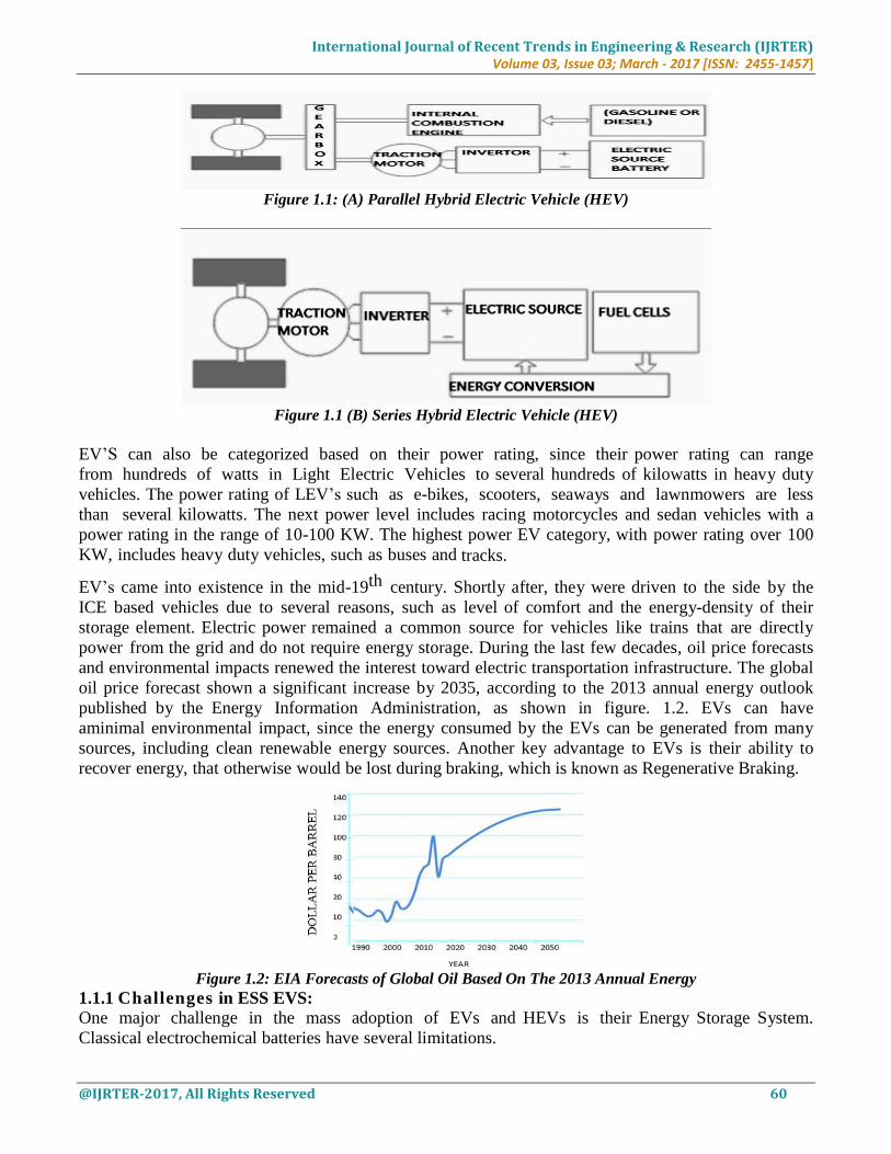
In a parallel design, the vehicle is powered by two independent mechanical drives, as shown in
Figure.1.1 (a). The electric motor only assists the primary engine in the events of acceleration, hill
climbing, braking etc.
In a series design, the vehicle is powered only by one mechanical drive as shown in Figure1.1
(b) and the primary engine charger the battery, which drives the electric motor.
In a parallel design, the highest power is delivered is 100 KW.
In a series design, as there is one mechanical drive so the power is 10-50KW.
The series and parallel design are started from 18th century.
International Journal of Recent Trends in Engineering & Research (IJRTER)
Volume 03, Issue 03; March - 2017 [ISSN: 2455-1457]
@IJRTER-2017, All Rights Reserved 60
Figure 1.1: (A) Parallel Hybrid Electric Vehicle (HEV)
Figure 1.1 (B) Series Hybrid Electric Vehicle (HEV)
EV’S can also be categorized based on their power rating, since their power rating can range
from hundreds of watts in Light Electric Vehicles to several hundreds of kilowatts in heavy duty
vehicles. The power rating of LEV’s such as e-bikes, scooters, seaways and lawnmowers are less
than several kilowatts. The next power level includes racing motorcycles and sedan vehicles with a
power rating in the range of 10-100 KW. The highest power EV category, with power rating over 100
KW, includes heavy duty vehicles, such as buses and tracks.
EV’s came into existence in the mid-19th century. Shortly after, they were driven to the side by the
ICE based vehicles due to several reasons, such as level of comfort and the energy-density of their
storage element. Electric power remained a common source for vehicles like trains that are directly
power from the grid and do not require energy storage. During the last few decades, oil price forecasts
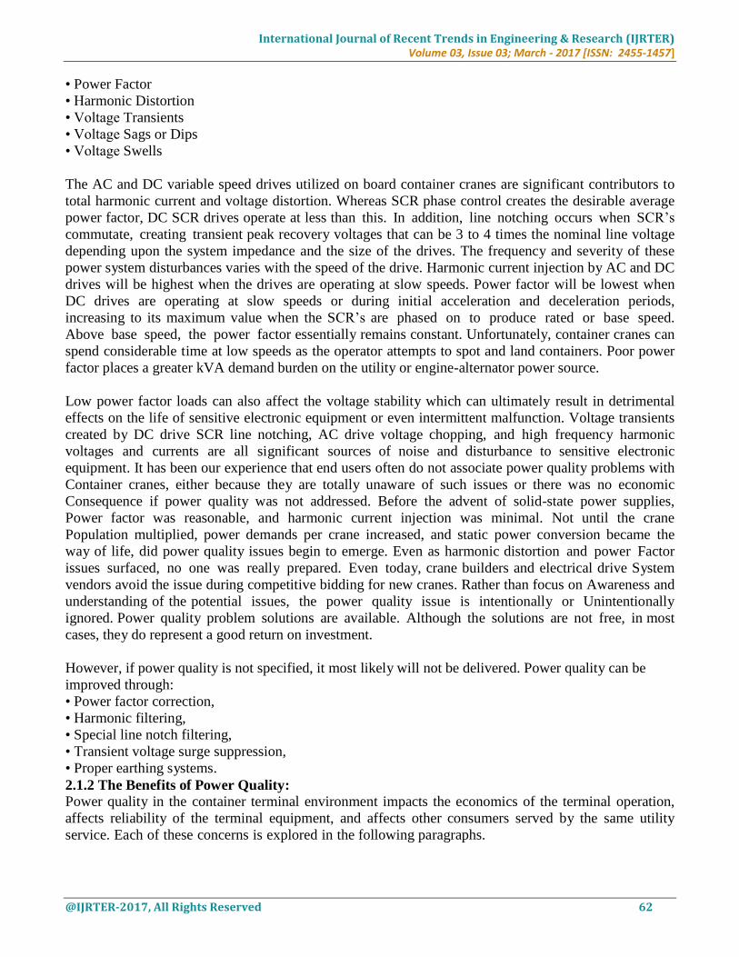
and environmental impacts renewed the interest toward electric transportation infrastructure. The global
oil price forecast shown a significant increase by 2035, according to the 2013 annual energy outlook
published by the Energy Information Administration, as shown in figure. 1.2. EVs can have
aminimal environmental impact, since the energy consumed by the EVs can be generated from many
sources, including clean renewable energy sources. Another key advantage to EVs is their ability to
recover energy, that otherwise would be lost during braking, which is known as Regenerative Braking.
Figure 1.2: EIA Forecasts of Global Oil Based On The 2013 Annual Energy
1.1.1 Challenges in ESS EVS: One major challenge in the mass adoption of EVs and HEVs is their Energy Storage System.
Classical electrochemical batteries have several limitations.

International Journal of Recent Trends in Engineering & Research (IJRTER)
Volume 03, Issue 03; March - 2017 [ISSN: 2455-1457]
@IJRTER-2017, All Rights Reserved 61
Lower energy-density compared to petrol-based fuel, which effects the weight and the range
of the vehicles. The specific-energy of petrol and Lithium-Ion batteries are 13KWh/Kg and 0.2
KWh/Kg respectively. Considering a typical energy efficiency of 20% for the ICEs and 90% for the
electric drives, the effective specific-energy of petrol is 14 times higher than that of Lithium-ion
batteries, resulting in a very limited range for EVs.
The charge time is another prohibitive factor and charging time varies with the charging
levels.The battery lifetime is another major concern and is usually not sufficient for traction
applications.
Numerous battery chemistries are available and the best choice of battery is application dependent.
A List of available battery chemistries is provided below:
1) Lead-Acid Batteries
2) Nickel-Metal Hydride Batteries
3) Lithium-Ion batteries.
4) Nickel-Zinc Batteries.
5) Nickel-Cadmium Batteries.
II. CUSTOM POWER DEVICES
2.1 Power Quality: Power Quality is term that means different things to different people. Institute of Electrical and
Electronic Engineers (IEEE) Standard IEEE defines power quality as “ the concept of powering and
grounding sensitive electronic equipment in a manner suitable for the equipment” All electrical
devices are prone to failure or malfunction when exposed to one or more power quality problems.
The electrical device might be an electric motor, a transformer, a generator, a computer, a printer,
communication equipment, or a household appliance. All of these devices and other react adversely to
power quality issues, depending on the severity of problems.
A simpler and perhaps more concise definition might state:”Power Quality is a set of electrical
boundaries that allows a piece of equipment to function in its intended manner without significant
loss of performance or life expectancy.” This definition embraces two things that we demand from an
electrical device: Performance and life expectancy. Any power related problem that compromises either
attribute is a power quality. From the following figure 2.1 shows the power quality beginning of
electricity i.e there is no disturbances, and figure 2.2 shows the power quality in Recent trends which
shows that there are many power quality problems.
Without disturbances
SOURCE LOAD
Figure: 2.1 Power Quality Beginning Of Electricity
SOURCE LOAD
Figure: 2.2 Power Quality In Recent Trends
2.1.1 Power Quality Problems: Any power problem that results in failure or misoperation of customer equipment, manifests itself as an
economic burden to the user, or produces negative impacts on the environment. When applied to the
container crane industry, the power issues which degrade power quality include:
International Journal of Recent Trends in Engineering & Research (IJRTER)
Volume 03, Issue 03; March - 2017 [ISSN: 2455-1457]
@IJRTER-2017, All Rights Reserved 62
• Power Factor
• Harmonic Distortion
• Voltage Transients
• Voltage Sags or Dips
• Voltage Swells
The AC and DC variable speed drives utilized on board container cranes are significant contributors to
total harmonic current and voltage distortion. Whereas SCR phase control creates the desirable average
power factor, DC SCR drives operate at less than this. In addition, line notching occurs when SCR’s
commutate, creating transient peak recovery voltages that can be 3 to 4 times the nominal line voltage
depending upon the system impedance and the size of the drives. The frequency and severity of these
power system disturbances varies with the speed of the drive. Harmonic current injection by AC and DC
drives will be highest when the drives are operating at slow speeds. Power factor will be lowest when
DC drives are operating at slow speeds or during initial acceleration and deceleration periods,
increasing to its maximum value when the SCR’s are phased on to produce rated or base speed.
Above base speed, the power factor essentially remains constant. Unfortunately, container cranes can
spend considerable time at low speeds as the operator attempts to spot and land containers. Poor power
factor places a greater kVA demand burden on the utility or engine-alternator power source.
Low power factor loads can also affect the voltage stability which can ultimately result in detrimental
effects on the life of sensitive electronic equipment or even intermittent malfunction. Voltage transients
created by DC drive SCR line notching, AC drive voltage chopping, and high frequency harmonic
voltages and currents are all significant sources of noise and disturbance to sensitive electronic
equipment. It has been our experience that end users often do not associate power quality problems with
Container cranes, either because they are totally unaware of such issues or there was no economic
Consequence if power quality was not addressed. Before the advent of solid-state power supplies,
Power factor was reasonable, and harmonic current injection was minimal. Not until the crane
Population multiplied, power demands per crane increased, and static power conversion became the
way of life, did power quality issues begin to emerge. Even as harmonic distortion and power Factor
issues surfaced, no one was really prepared. Even today, crane builders and electrical drive System
vendors avoid the issue during competitive bidding for new cranes. Rather than focus on Awareness and
understanding of the potential issues, the power quality issue is intentionally or Unintentionally
ignored. Power quality problem solutions are available. Although the solutions are not free, in most
cases, they do represent a good return on investment.
However, if power quality is not specified, it most likely will not be delivered. Power quality can be
improved through:
• Power factor correction,
• Harmonic filtering,
• Special line notch filtering,
• Transient voltage surge suppression,
• Proper earthing systems.
2.1.2 The Benefits of Power Quality: Power quality in the container terminal environment impacts the economics of the terminal operation,
affects reliability of the terminal equipment, and affects other consumers served by the same utility
service. Each of these concerns is explored in the following paragraphs.
International Journal of Recent Trends in Engineering & Research (IJRTER)
Volume 03, Issue 03; March - 2017 [ISSN: 2455-1457]
@IJRTER-2017, All Rights Reserved 63
2.1.3 Classification according to power circuit, configurations and connections: The choice of power circuit chosen for the active filter greatly influences its efficiency and accuracy in
providing true compensation. It is therefore important that the correct circuit configuration is chosen.
Three major types of filter structures shown in figure 2.5 along with the relevant power circuit. There
are
(i) Shunt active filters
(ii) Series active filters
(iii) Other filter configurations
Figure: 2.5 Subdivisions of Active Power Filter according To Power Circuit connections
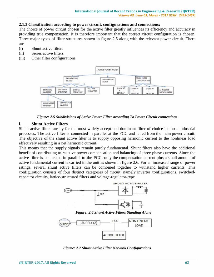
i. Shunt Active Filters Shunt active filters are by far the most widely accept and dominant filter of choice in most industrial
processes. The active filter is connected in parallel at the PCC and is fed from the main power circuit.
The objective of the shunt active filter is to supply opposing harmonic current to the nonlinear load
effectively resulting in a net harmonic current.
This means that the supply signals remain purely fundamental. Shunt filters also have the additional
benefit of contributing to reactive power compensation and balancing of three-phase currents. Since the
active filter is connected in parallel to the PCC, only the compensation current plus a small amount of
active fundamental current is carried in the unit as shown in figure 2.6. For an increased range of power
ratings, several shunt active filters can be combined together to withstand higher currents. This
configuration consists of four distinct categories of circuit, namely inverter configurations, switched-
capacitor circuits, lattice-structured filters and voltage-regulator-type
Figure: 2.6 Shunt Active Filters Standing Alone
Figure: 2.7 Shunt Active Filter Network Configurations
International Journal of Recent Trends in Engineering & Research (IJRTER)
Volume 03, Issue 03; March - 2017 [ISSN: 2455-1457]
@IJRTER-2017, All Rights Reserved 64
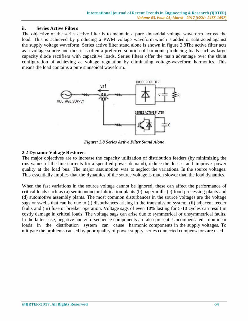
ii. Series Active Filters The objective of the series active filter is to maintain a pure sinusoidal voltage waveform across the
load. This is achieved by producing a PWM voltage waveform which is added or subtracted against
the supply voltage waveform. Series active filter stand alone is shown in figure 2.8The active filter acts
as a voltage source and thus it is often a preferred solution of harmonic producing loads such as large
capacity diode rectifiers with capacitive loads. Series filters offer the main advantage over the shunt
configuration of achieving ac voltage regulation by eliminating voltage-waveform harmonics. This
means the load contains a pure sinusoidal waveform.
Figure: 2.8 Series Active Filter Stand Alone
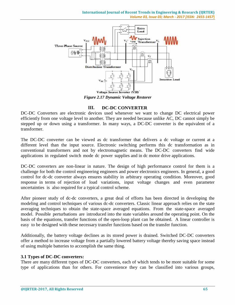
2.2 Dynamic Voltage Restorer: The major objectives are to increase the capacity utilization of distribution feeders (by minimizing the
rms values of the line currents for a specified power demand), reduce the losses and improve power
quality at the load bus. The major assumption was to neglect the variations. In the source voltages.
This essentially implies that the dynamics of the source voltage is much slower than the load dynamics.
When the fast variations in the source voltage cannot be ignored, these can affect the performance of
critical loads such as (a) semiconductor fabrication plants (b) paper mills (c) food processing plants and
(d) automotive assembly plants. The most common disturbances in the source voltages are the voltage
sags or swells that can be due to (i) disturbances arising in the transmission system, (ii) adjacent feeder
faults and (iii) fuse or breaker operation. Voltage sags of even 10% lasting for 5-10 cycles can result in
costly damage in critical loads. The voltage sags can arise due to symmetrical or unsymmetrical faults.
In the latter case, negative and zero sequence components are also present. Uncompensated nonlinear
loads in the distribution system can cause harmonic components in the supply voltages. To
mitigate the problems caused by poor quality of power supply, series connected compensators are used.
International Journal of Recent Trends in Engineering & Research (IJRTER)
Volume 03, Issue 03; March - 2017 [ISSN: 2455-1457]
@IJRTER-2017, All Rights Reserved 65
Figure 2.17 Dynamic Voltage Restorer
III. DC-DC CONVERTER
DC-DC Converters are electronic devices used whenever we want to change DC electrical power
efficiently from one voltage level to another. They are needed because unlike AC, DC cannot simply be
stepped up or down using a transformer. In many ways, a DC-DC converter is the equivalent of a
transformer.
The DC-DC converter can be viewed as dc transformer that delivers a dc voltage or current at a
different level than the input source. Electronic switching performs this dc transformation as in
conventional transformers and not by electromagnetic means. The DC-DC converters find wide
applications in regulated switch mode dc power supplies and in dc motor drive applications.
DC-DC converters are non-linear in nature. The design of high performance control for them is a
challenge for both the control engineering engineers and power electronics engineers. In general, a good
control for dc-dc converter always ensures stability in arbitrary operating condition. Moreover, good
response in terms of rejection of load variations, input voltage changes and even parameter
uncertainties is also required for a typical control scheme.
After pioneer study of dc-dc converters, a great deal of efforts has been directed in developing the
modeling and control techniques of various dc-dc converters. Classic linear approach relies on the state
averaging techniques to obtain the state-space averaged equations. From the state-space averaged
model. Possible perturbations are introduced into the state variables around the operating point. On the
basis of the equations, transfer functions of the open-loop plant can be obtained. A linear controller is
easy to be designed with these necessary transfer functions based on the transfer function.
Additionally, the battery voltage declines as its stored power is drained. Switched DC-DC converters
offer a method to increase voltage from a partially lowered battery voltage thereby saving space instead
of using multiple batteries to accomplish the same thing.
3.1 Types of DC-DC converters: There are many different types of DC-DC converters, each of which tends to be more suitable for some
type of applications than for others. For convenience they can be classified into various groups,

International Journal of Recent Trends in Engineering & Research (IJRTER)
Volume 03, Issue 03; March - 2017 [ISSN: 2455-1457]
@IJRTER-2017, All Rights Reserved 66
however for example some converters are only suitable for stepping down the voltage, while others are
only suitable for stepping it up a third group can be used for either.
Currently DC-DC converters can be divided into two types
Non –isolated dc-dc converters.
Isolated dc-dc converters.
IV. SUPER CAPACITOR
4.1 Definition: CAPACITOR: It is a device to store the charge in an electric circuit.
SUPER CAPACITOR: It can be defined as a energy storage device that stores energy electro
statically by polarizing an electrolytic solution.
Basically a capacitor is made up of two conductors separated by an insulator called dielectric. The
dielectric can be made of paper, plastic, mica, ceramic, glass a vacuum or nearly any other
nonconductive material. Some capacitors are called Electrolytic in which the dielectric is aluminium foil
conductor coated with oxide layer.
The electron storing capacity of capacitor is measured in units Farads. One Farad is approximately the
charge with 6,280,000,000,000,000,000. Unlike batteries no chemical reaction takes place when energy
is being stored or discharged and so super capacitors can go through hundreds of charging cycles
with no degradation. Super capacitors are also known as double-layer capacitors or ultra capacitors
4.2 Principle of Super Capacitor: Energy is stored in super capacitor by polarizing the electrolytic solution. The charges are separated via
electrode-electrolyte interface as shown in figure 4.1.
Figure 4.1 Principle Of Super capacitor
4.3 Block Diagram of Super Capacitor:
Figure 4.2 Block Diagram of Super Capacitor
International Journal of Recent Trends in Engineering & Research (IJRTER)
Volume 03, Issue 03; March - 2017 [ISSN: 2455-1457]
@IJRTER-2017, All Rights Reserved 67
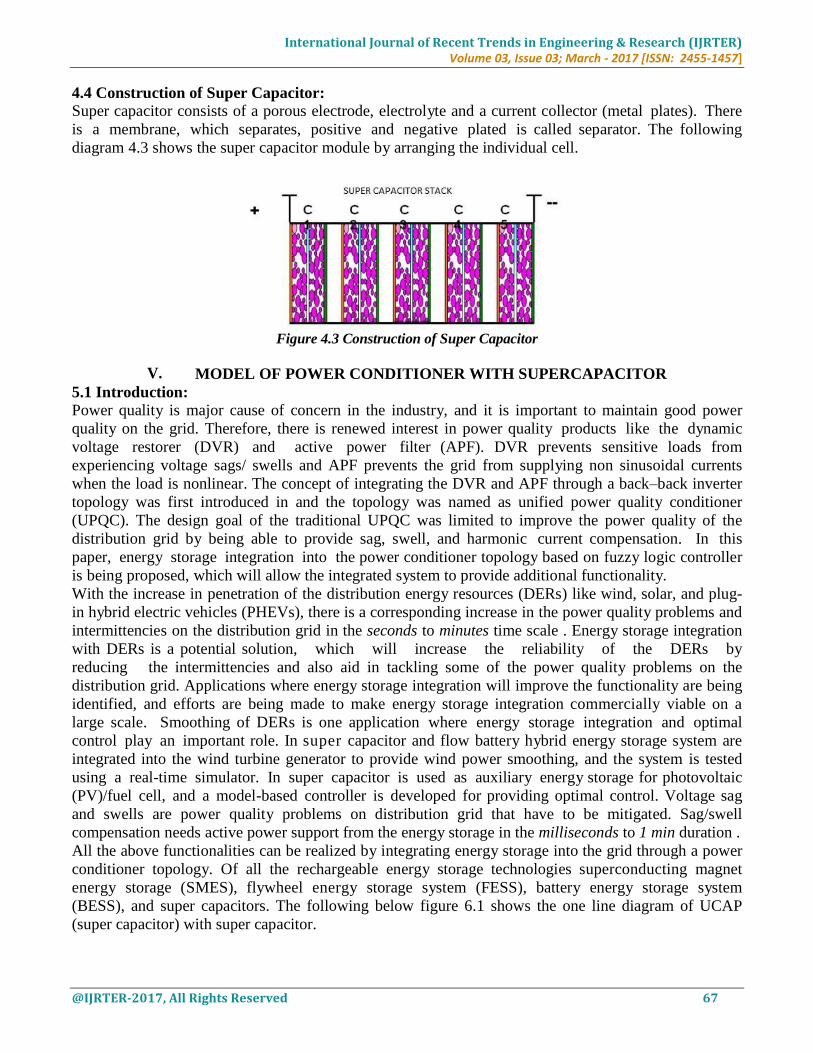
4.4 Construction of Super Capacitor: Super capacitor consists of a porous electrode, electrolyte and a current collector (metal plates). There
is a membrane, which separates, positive and negative plated is called separator. The following
diagram 4.3 shows the super capacitor module by arranging the individual cell.
Figure 4.3 Construction of Super Capacitor
V. MODEL OF POWER CONDITIONER WITH SUPERCAPACITOR
5.1 Introduction: Power quality is major cause of concern in the industry, and it is important to maintain good power
quality on the grid. Therefore, there is renewed interest in power quality products like the dynamic
voltage restorer (DVR) and active power filter (APF). DVR prevents sensitive loads from
experiencing voltage sags/ swells and APF prevents the grid from supplying non sinusoidal currents
when the load is nonlinear. The concept of integrating the DVR and APF through a back–back inverter
topology was first introduced in and the topology was named as unified power quality conditioner
(UPQC). The design goal of the traditional UPQC was limited to improve the power quality of the
distribution grid by being able to provide sag, swell, and harmonic current compensation. In this
paper, energy storage integration into the power conditioner topology based on fuzzy logic controller
is being proposed, which will allow the integrated system to provide additional functionality.
With the increase in penetration of the distribution energy resources (DERs) like wind, solar, and plug-
in hybrid electric vehicles (PHEVs), there is a corresponding increase in the power quality problems and
intermittencies on the distribution grid in the seconds to minutes time scale . Energy storage integration
with DERs is a potential solution, which will increase the reliability of the DERs by
reducing the intermittencies and also aid in tackling some of the power quality problems on the
distribution grid. Applications where energy storage integration will improve the functionality are being
identified, and efforts are being made to make energy storage integration commercially viable on a
large scale. Smoothing of DERs is one application where energy storage integration and optimal
control play an important role. In super capacitor and flow battery hybrid energy storage system are
integrated into the wind turbine generator to provide wind power smoothing, and the system is tested
using a real-time simulator. In super capacitor is used as auxiliary energy storage for photovoltaic
(PV)/fuel cell, and a model-based controller is developed for providing optimal control. Voltage sag
and swells are power quality problems on distribution grid that have to be mitigated. Sag/swell
compensation needs active power support from the energy storage in the milliseconds to 1 min duration .
All the above functionalities can be realized by integrating energy storage into the grid through a power
conditioner topology. Of all the rechargeable energy storage technologies superconducting magnet
energy storage (SMES), flywheel energy storage system (FESS), battery energy storage system
(BESS), and super capacitors. The following below figure 6.1 shows the one line diagram of UCAP
(super capacitor) with super capacitor.

International Journal of Recent Trends in Engineering & Research (IJRTER)
Volume 03, Issue 03; March - 2017 [ISSN: 2455-1457]
@IJRTER-2017, All Rights Reserved 68
Figure 5.1 One line diagram of Power Conditioner with super capacitor Storage
Figure 5.2 Model of Power Conditioner with super capacitor energy storage
5.2 Description of Block Diagram:
The theme of the block diagram is to maintain constant power output to the load as shown in the figure.
But due to power quality issues the power to the load is not constant and it is disturbed by various
problems like sags, swells and harmonics,
So, in order to reduce those problems a 3-phase Dynamic Voltage Restorer is used which is in series
with the distribution grid. The operation of the DVR is to inject voltage whenever there is a drop in the
line.
To reduce the current harmonics which is produced in the model a 3-phase shunt active power
filter is used which is connected in shunt to the grid.
A Super Capacitor also known as UCAP is used in order to deliver the power to the dc link from dc/dc
converter. A dc/dc converter is known as buck-boost converter.
International Journal of Recent Trends in Engineering & Research (IJRTER)
Volume 03, Issue 03; March - 2017 [ISSN: 2455-1457]
@IJRTER-2017, All Rights Reserved 69
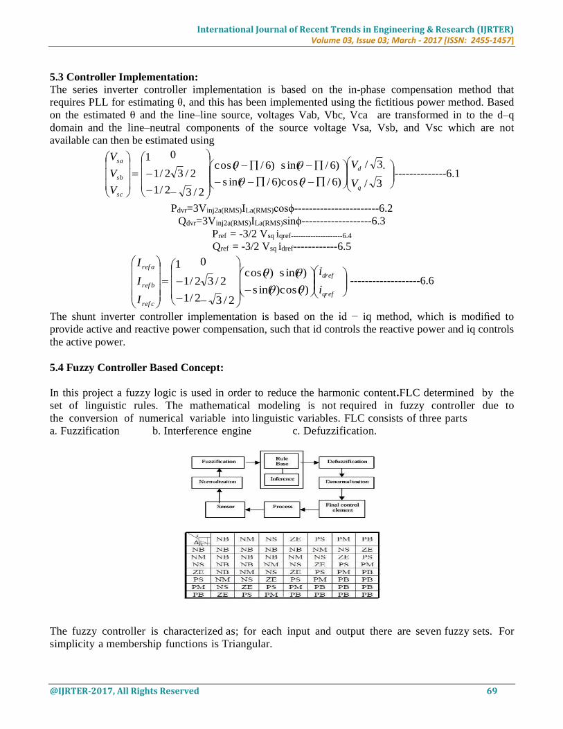
5.3 Controller Implementation: The series inverter controller implementation is based on the in-phase compensation method that
requires PLL for estimating θ, and this has been implemented using the fictitious power method. Based
on the estimated θ and the line–line source, voltages Vab, Vbc, Vca are transformed in to the d–q
domain and the line–neutral components of the source voltage Vsa, Vsb, and Vsc which are not
available can then be estimated using
.
3/
3/
)6/cos (
)6/s in(
)6/s in(
)6/cos (
2/3
2/3
0
2/1
2/1
1
q
d
sc
sb
sa
V
V
V
V
V
--------------6.1
Pdvr=3Vinj2a(RMS)ILa(RMS)cosϕ-----------------------6.2
Qdvr=3Vinj2a(RMS)ILa(RMS)sinϕ-------------------6.3
Pref = -3/2 Vsq iqref---------------------6.4
Qref = -3/2 Vsq idref------------6.5
qref
dref
ref c
ref b
ref a
i
i
I
I
I
)cos (
)s in(
)s in(
)cos (
2/3
2/3
0
2/1
2/1
1
-------------------6.6
The shunt inverter controller implementation is based on the id − iq method, which is modified to
provide active and reactive power compensation, such that id controls the reactive power and iq controls
the active power.
5.4 Fuzzy Controller Based Concept:
In this project a fuzzy logic is used in order to reduce the harmonic content.FLC determined by the
set of linguistic rules. The mathematical modeling is not required in fuzzy controller due to
the conversion of numerical variable into linguistic variables. FLC consists of three parts
a. Fuzzification b. Interference engine c. Defuzzification.
The fuzzy controller is characterized as; for each input and output there are seven fuzzy sets. For
simplicity a membership functions is Triangular.

International Journal of Recent Trends in Engineering & Research (IJRTER)
Volume 03, Issue 03; March - 2017 [ISSN: 2455-1457]
@IJRTER-2017, All Rights Reserved 70
a) Fuzzification: - Fuzzification is using continuous universe of discourse. Implication is
using Mamdani's "min" operator. Defuzzification is using the "height" method. Membership
function values are assigned to the linguistic variables, using seven fuzzy subsets:
NB(Negative Big), NM(Negative Medium), NS (Negative Small), ZE (Zero), PS (Positive
Small),PM(Positive Medium) and PB (Positive Big). The partition of fuzzy subsets and the shape
of membership function adapt the shape up to appropriate system. Input error E(k) and change in
error CE(k) of values which is normalized by an input scaling factor .
In this system the input scaling factor is between -1 and +1 has design. The triangular shape of the
membership function of this arrangement presumes that for any particular input there is only one
dominant fuzzy subset.
b. Inference Method: Several composition methods such as Max-Min and Max-Dot have been proposed and Min
method is used. Minimum operator and Maximum operator of output membership function is of
each rule.
c. Defuzzification: As a plant usually requires a non-fuzzy value of control, a defuzzification stage is needed. To
compute the output of the FLC, "height" method is used and the FLC output modifies the control
output. Further, the output of FLC controls the switch in the inverter. In order to control these
parameters, they are sensed and compared with the reference values. To achieve this, the
membership functions of Fuzzy controller are: error, change in error and output.
Figure: 5.3 Fuzzy Inference System In Simulink Software
International Journal of Recent Trends in Engineering & Research (IJRTER)
Volume 03, Issue 03; March - 2017 [ISSN: 2455-1457]
@IJRTER-2017, All Rights Reserved 71
VI. MATLAB/SIMULATION RESULTS
6.1 Simulink Diagrams:
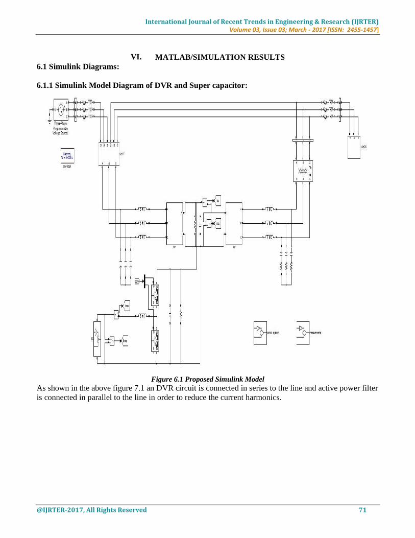
6.1.1 Simulink Model Diagram of DVR and Super capacitor:
Figure 6.1 Proposed Simulink Model
As shown in the above figure 7.1 an DVR circuit is connected in series to the line and active power filter
is connected in parallel to the line in order to reduce the current harmonics.
International Journal of Recent Trends in Engineering & Research (IJRTER)
Volume 03, Issue 03; March - 2017 [ISSN: 2455-1457]
@IJRTER-2017, All Rights Reserved 72
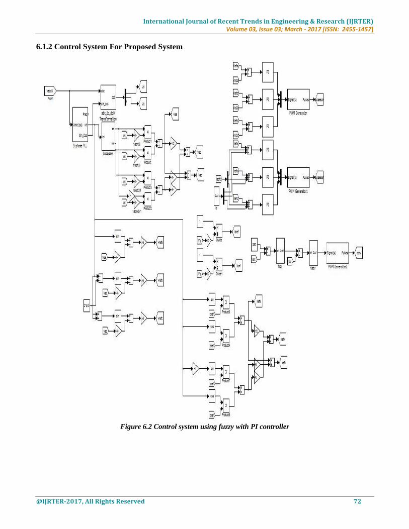
6.1.2 Control System For Proposed System
Figure 6.2 Control system using fuzzy with PI controller

International Journal of Recent Trends in Engineering & Research (IJRTER)
Volume 03, Issue 03; March - 2017 [ISSN: 2455-1457]
@IJRTER-2017, All Rights Reserved 73
As shown in the above figure 7.2 an PI controller as well as fuzzy logic controller is designed in order
improve the accuracy and to reduce the total harmonic distortion.
The P W M Generator block generates pulses for carrier-based pulse w i d t h modulation
(PWM) converters using two-level topology. The block can be used to fire the forced-commutated
devices (FETs, GTOs, or IGBTs) of single-phase, two-phase, three-phase, two-level bridges or a
combination of two three-phase bridges.
The Fuzzy Logic Controller block implements a fuzzy inference system (FIS) in Simulink.
6.2 Simulink Results:
6.2.1 Source and Load RMS Voltages:
Figure 6.3 Source and Load Rms Voltages during Sag Condition
As shown in the above figure 7.3 yellow colour represents the load rms voltage. The reason for
decreasing the load rms voltage is due to the sag occurs in the system. The above waveform is
represented in per unit values.
6.2.2 Source Voltages during Sag Condition
Figure 6.4 Source Voltage During Sag Condition
The above figure 6.4 represents the three phase voltages during sag condition. This drop due to sag is
recovered by dynamic voltage restorer.
6.2.3 Injected Voltages during Sag Condition
Figure 6.5 Injected Voltage During Sag Condition

International Journal of Recent Trends in Engineering & Research (IJRTER)
Volume 03, Issue 03; March - 2017 [ISSN: 2455-1457]
@IJRTER-2017, All Rights Reserved 74
The above figure 6.5 shows the voltages by dynamic voltage restorer which is injected to the line
6.2.4 Load Voltages During Sag Condition
Figure 6.6 Load Voltages during Sag Condition
The above figure 6.6 shows the final load voltages during sag condition. Although voltages dropped due
to sag the dynamic voltage restorer recovered the voltage.
6.2.5 Currents and Voltages Of DC-DC Converter
Figure 6.7 Voltages And Currents Of DC-DC Converter
The above figure 6.7 represents the voltages and currents of dc-dc converter during the sag condition.
6.2.6 Active and Reactive Power Of Grid, Load And Inverter During Voltage Sag.
Figure 6.8 Active and Reactive Power of Grid, Load during Sag Condition
The above figure 6.8 represents Pload , Pdcin , Pgrid , Pdvr and Qload , Qdvr , Qgrid

International Journal of Recent Trends in Engineering & Research (IJRTER)
Volume 03, Issue 03; March - 2017 [ISSN: 2455-1457]
@IJRTER-2017, All Rights Reserved 75
6.2.7 Total Harmonic Distortion Using With Out Fuzzy Controller
Figure 6.9 THD With Out Fuzzy Controller
6.2.8 Total Harmonic Distortion Using With Fuzzy Controller
Figure 6.10 THD with Fuzzy Controller
VII. CONCLUSION
In this project, the concept of integrating super capacitor-based rechargeable energy storage to a
power conditioner system to improve the power quality of the distribution grid along with implementing
fuzzy logic controller is presented. With this integration, the DVR portion of the power conditioner will
be able to independently compensate voltage sags and swells and the APF portion of the power
conditioner will be able to provide active/reactive power support and renewable intermittency
smoothing to the distribution grid. Super capacitor integration through a bidirectional dc–dc converter
at the dc-link of the power conditioner is proposed. . Similar UCAP based energy storages can be
deployed in the future in a microgrid or a low-voltage distribution grid to respond to dynamic changes
in the voltage profiles and power profiles on the distribution grid.
FUTURE SCOPE
1) An Multi Level Custom Power Devices Like DVR With Fuzzy Logic Controller Can Be
Investigated
2) This Model Presented In This Paper Will Applicable To Power Electronic Loads Used In Modern
Hi-Tech Industry.
3) This Fuzzy Logic Controller Based Model Is Implemented To Integrated Power Plants In Order To
Reduce The Total Harmonic Distortion, There By Power Quality Is Increased.
REFERENCES [1] Deepak Somayajula, Student Member, IEEE, and Mariesa L. Crow, Fellow, IEEE,” An Ultra capacitor Integrated Power
Conditioner for Intermittency Smoothing and Improving Power Quality of Distribution Grid” , IEEE TRANSACTIONS ON
SUSTAINABLE ENERGY, VOL.
5, NO. 4, OCTOBER 2014.
International Journal of Recent Trends in Engineering & Research (IJRTER)
Volume 03, Issue 03; March - 2017 [ISSN: 2455-1457]
@IJRTER-2017, All Rights Reserved 76
[2] Shailesh M. Deshmukh, Bharti Dewani / International Journal of Engineering Research and Applications , Overview of
Dynamic Voltage Restorer (DVR) for Power Quality Improvement.
[3] J. G. Nielsen, M. Newman, H. Nielsen, and F. Blaabjerg, “Control and testing of a dynamic voltage restorer (DVR) at
medium voltage level,” IEEE Trans. Power Electron., vol. 19, no. 3, pp. 806–813, May 2004.
[4] V. Soares, P. Verdelho, and G. D. Marques, “An instantaneous active and reactive current component method for active
filters,” IEEE Trans. Power Electron., vol. 15, no. 4, pp. 660–669, Jul. 2000.
[5] Neha Kumari1, Isha Awashthi IEC College of Engineering and Technology, Greater Noida, Uttar Pradesh, India
“Harmonic Compensation Using Shunt Active Power Filter in Power System Using Matlab” International Journal of
Scientific Engineering and Research (IJSER)”.
[6] K. Sahay and B. Dwivedi, “Supercapacitors energy storage system for power quality improvement: An
overview,” J. Energy Sources, vol. 10, no. 10, pp. 1–8, 2009.
[7] B. M. Han and B. Bae, “Unified power quality conditioner with super-capacitor for energy storage,” Eur. Trans.
Elect. Power, vol. 18, pp. 327–343, Apr. 2007.
[8] P. F. Ribeiro, B. K. Johnson, M. L. Crow, A. Arsoy, and Y. Liu, “Energy storage systems for advanced power
applications,” Proc. IEEE, vol. 89, no. 12, pp. 1744–1756, Dec. 2001.
[9] Geethu M. Suresh1, Jancy Varghese “A New Harmonic Elimination Technique Using Shunt Active Filter and PI
Controller” September 2015 | IJIRT | Volume 2 Issue 4 | ISSN: 2349-6002


![On the Fixed-Interval Smoothing Problem+willsky.lids.mit.edu/publ_pdfs/32_pub_STO.pdfexperimental data analysis and has been the subject of much attention [I], [2]. Smoothing refers](https://static.fdocuments.us/doc/165x107/60cf899fd68ca001d601a99f/on-the-fixed-interval-smoothing-problem-experimental-data-analysis-and-has-been.jpg)

