Improvement of the Polaris Switchback Assault: · PDF fileImprovement of the Polaris...
15
Page 1 of 15 Improvement of the Polaris Switchback Assault: Innovations for a Greener Tomorrow Dylan Truskolaski, Clayton Hendricks, John Keepers, Chad Kromrey, Lauren Nasca, Dr. Jason R Blough Michigan Technological University Copyright © 2012 SAE International ABSTRACT The Michigan Technological University (MTU) Clean Snowmobile Team is entering the 2011 SAE International Clean Snowmobile Challenge with a redesigned 2011 Polaris Switchback Assault. The snowmobile has been redesigned to operate with reduced noise, reduced emissions, and with greater fuel efficiency. The snowmobile has been equipped with a turbocharged four stroke750cc Weber engine, AEM engine management system, a Siemens fuel composition sensor, lightweight electric charging system, and MTU designed intake and exhaust system. INTRODUCTION To address concerns about the environmental impact of snowmobiles in Yellowstone National Park, the Clean Snowmobile Challenge was introduced in the winter of 2000 in Jackson Hole, Wyoming. The goal was to invite university students to design and produce a cleaner and quieter touring snowmobile to be ridden primarily on groomed snowmobile trails throughout the park. This event was sponsored by SAE International and consisted of universities from across the United States and Canada, all of which arrived with snowmobiles they had designed and built. The snowmobiles were evaluated in several static and dynamic events, including acceleration, handling, and hill climbs. In 2003, the competition was moved to the Upper Peninsula of Michigan and was hosted by the Keweenaw Research Center (KRC) just north of Michigan Technological University’s campus. For 2011, the competition remains at the KRC and runs from March 5 th to the 10 th . The competition has evolved to include both internal combustion snowmobiles as well as zero emissions electric-powered snowmobiles. In 2011 the MTU Clean Snowmobile Team placed sixth overall in the internal combustion category. Table 1 shows a breakdown of the team’s performance from the 2011 competition.
Transcript of Improvement of the Polaris Switchback Assault: · PDF fileImprovement of the Polaris...

Page 1 of 15
Improvement of the Polaris Switchback Assault: Innovations for a Greener Tomorrow
Dylan Truskolaski, Clayton Hendricks, John Keepers, Chad Kromrey, Lauren Nasca,
Dr. Jason R Blough Michigan Technological University
Copyright © 2012 SAE International
ABSTRACT
The Michigan Technological University (MTU) Clean Snowmobile Team is entering the 2011 SAE International Clean Snowmobile Challenge with a redesigned 2011 Polaris Switchback Assault. The snowmobile has been redesigned to operate with reduced noise, reduced emissions, and with greater fuel efficiency. The snowmobile has been equipped with a turbocharged four stroke750cc Weber engine, AEM engine management system, a Siemens fuel composition sensor, lightweight electric charging system, and MTU designed intake and exhaust system.
INTRODUCTION To address concerns about the environmental impact of snowmobiles in Yellowstone National Park, the Clean Snowmobile Challenge was introduced in the winter of 2000 in Jackson Hole, Wyoming. The goal was to invite university students to design and produce a cleaner and quieter touring snowmobile to be ridden primarily on groomed snowmobile trails throughout the park. This event was sponsored by SAE International and consisted of universities from across the United States and Canada, all of which arrived with snowmobiles they had designed and built. The snowmobiles were evaluated in several static and dynamic events, including acceleration, handling, and hill climbs. In 2003, the competition was moved to the Upper Peninsula of Michigan and was hosted by the Keweenaw Research Center (KRC) just north of Michigan Technological University’s campus. For 2011, the competition remains at the KRC and runs from March 5th
to the 10th. The competition has evolved to include both internal combustion snowmobiles as well as zero emissions electric-powered snowmobiles. In 2011 the MTU Clean Snowmobile Team placed sixth overall in the internal combustion category. Table 1 shows a breakdown of the team’s performance from the 2011 competition.
Page 2 of 15
Table 1 - 2011 MTU Clean Snowmobile competition results.
Event Score Place
(out of 13) Design Paper 82.2/100 3 Static Display 50.0/50 MSRP 0.0 13 Subjective Handling 25.9/50 6
Fuel Economy 0/200 DNF
Endurance Oral Presentation 85.4/100 5 Noise 0.0/100 DNF Acceleration 49.1/50 2 Lab Emissions/BSFC 1.7/350 FAIL Fuel Economy/ In service Emissions
24.7/100 7
Cold Start 50/50 Objective Handling 61.0/75 2 Penalties/Bonuses -10
For 2012, the team focused on improving the overall performance as well as reducing the weight of the snowmobile. The goals were to improve horsepower by 10% and reduce weight by 10% compared to the 2011 MTU entry. Based on the results of the 2011 competition and the focus for 2012, the team formulated a list of goals for 2012 which can be seen in Table 2.
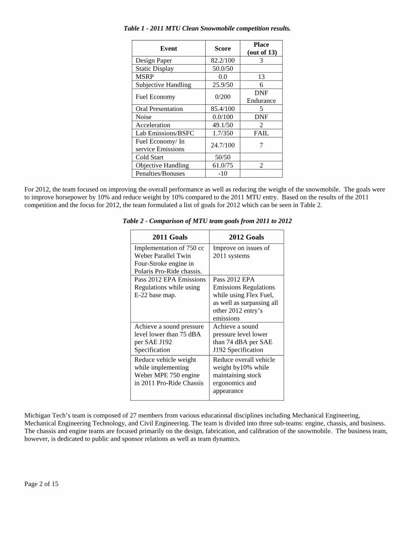
Table 2 - Comparison of MTU team goals from 2011 to 2012
Michigan Tech’s team is composed of 27 members from various educational disciplines including Mechanical Engineering, Mechanical Engineering Technology, and Civil Engineering. The team is divided into three sub-teams: engine, chassis, and business. The chassis and engine teams are focused primarily on the design, fabrication, and calibration of the snowmobile. The business team, however, is dedicated to public and sponsor relations as well as team dynamics.
2011 Goals 2012 Goals
Implementation of 750 cc Weber Parallel Twin Four-Stroke engine in Polaris Pro-Ride chassis.
Improve on issues of 2011 systems
Pass 2012 EPA Emissions Regulations while using E-22 base map.
Pass 2012 EPA Emissions Regulations while using Flex Fuel, as well as surpassing all other 2012 entry’s emissions
Achieve a sound pressure level lower than 75 dBA per SAE J192 Specification
Achieve a sound pressure level lower than 74 dBA per SAE J192 Specification
Reduce vehicle weight while implementing Weber MPE 750 engine in 2011 Pro-Ride Chassis
Reduce overall vehicle weight by10% while maintaining stock ergonomics and appearance
Page 3 of 15
PERFORMANCE THROUGH INNOVATION
With implementation of the turbo-charged Weber MPE 750cc four-stroke engine into the modern 2011 Polaris Pro-Ride Switchback Assault Chassis and the use of light weight components, the 2012 MTU Clean Snowmobile IC entry weighs in at one hundred pounds less than the stock 2012 Polaris IQ Turbo. The 2012 MTU Clean Snowmobile is not only clean and quiet, but is also lighter and more powerful than the 2011 entry. This makes the ride more enjoyable; closely replicating the ride of a lighter, two-stroke snowmobile with a significant increase in performance, fuel economy, reliability, and a reduction in maintenance cost.
The 2012 MTU entry closely resembles a modern, market available Polaris snowmobile. Through careful planning the ergonomics of the snowmobile remain similar to that of the OEM model. However, new developments such as change to the four-stroke engine, implementation of a flex fuel sensor, engine modifications, enhancement of exhaust and intake systems, tunnel modifications, suspension modifications, and engine calibration were implemented into the 2012 entry to increase its desirability while decreasing its environmental impact.
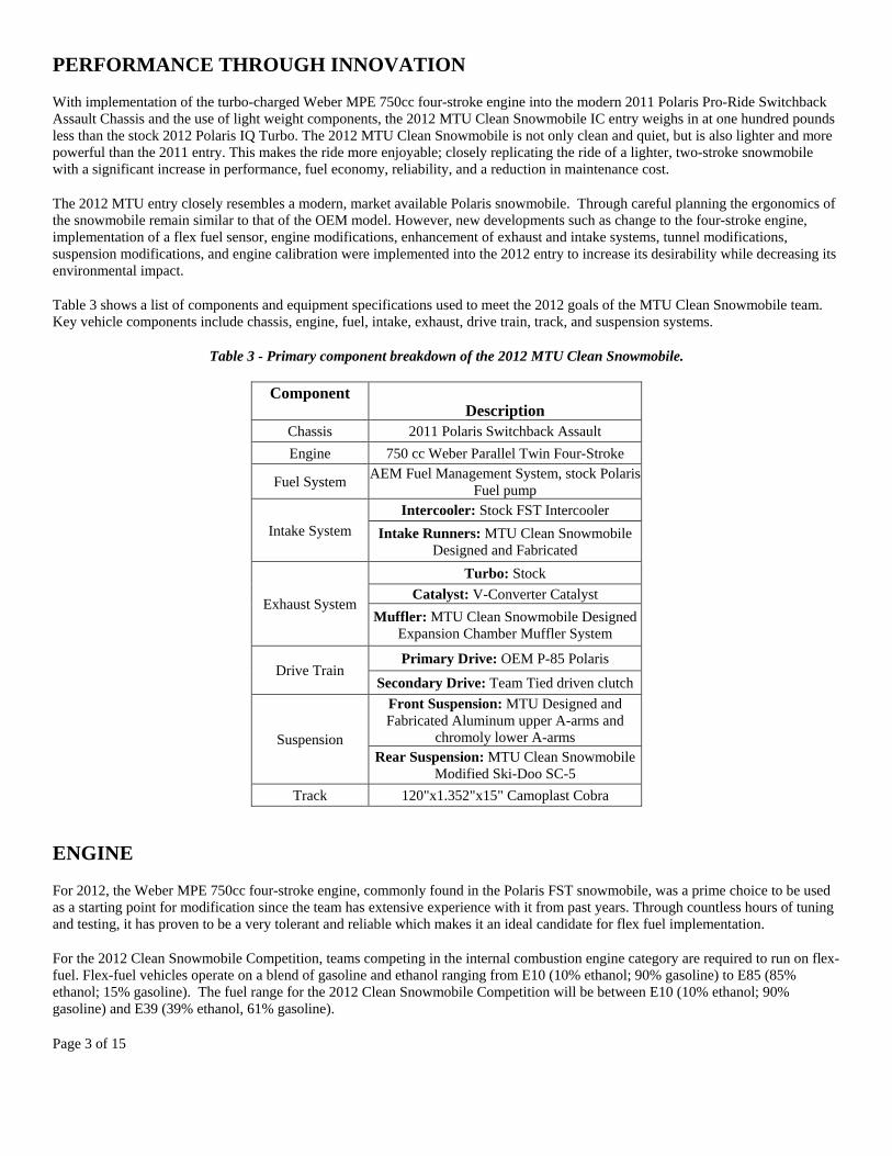
Table 3 shows a list of components and equipment specifications used to meet the 2012 goals of the MTU Clean Snowmobile team. Key vehicle components include chassis, engine, fuel, intake, exhaust, drive train, track, and suspension systems.
Table 3 - Primary component breakdown of the 2012 MTU Clean Snowmobile.
Component Description
Chassis 2011 Polaris Switchback Assault
Engine 750 cc Weber Parallel Twin Four-Stroke
Fuel System AEM Fuel Management System, stock Polaris
Fuel pump
Intake System
Intercooler: Stock FST Intercooler
Intake Runners: MTU Clean Snowmobile Designed and Fabricated
Exhaust System
Turbo: Stock
Catalyst: V-Converter Catalyst
Muffler: MTU Clean Snowmobile Designed Expansion Chamber Muffler System
Drive Train Primary Drive: OEM P-85 Polaris
Secondary Drive: Team Tied driven clutch
Suspension
Front Suspension: MTU Designed and Fabricated Aluminum upper A-arms and
chromoly lower A-arms Rear Suspension: MTU Clean Snowmobile
Modified Ski-Doo SC-5
Track 120"x1.352"x15" Camoplast Cobra
ENGINE
For 2012, the Weber MPE 750cc four-stroke engine, commonly found in the Polaris FST snowmobile, was a prime choice to be used as a starting point for modification since the team has extensive experience with it from past years. Through countless hours of tuning and testing, it has proven to be a very tolerant and reliable which makes it an ideal candidate for flex fuel implementation.
For the 2012 Clean Snowmobile Competition, teams competing in the internal combustion engine category are required to run on flex-fuel. Flex-fuel vehicles operate on a blend of gasoline and ethanol ranging from E10 (10% ethanol; 90% gasoline) to E85 (85% ethanol; 15% gasoline). The fuel range for the 2012 Clean Snowmobile Competition will be between E10 (10% ethanol; 90% gasoline) and E39 (39% ethanol, 61% gasoline).
Page 4 of 15
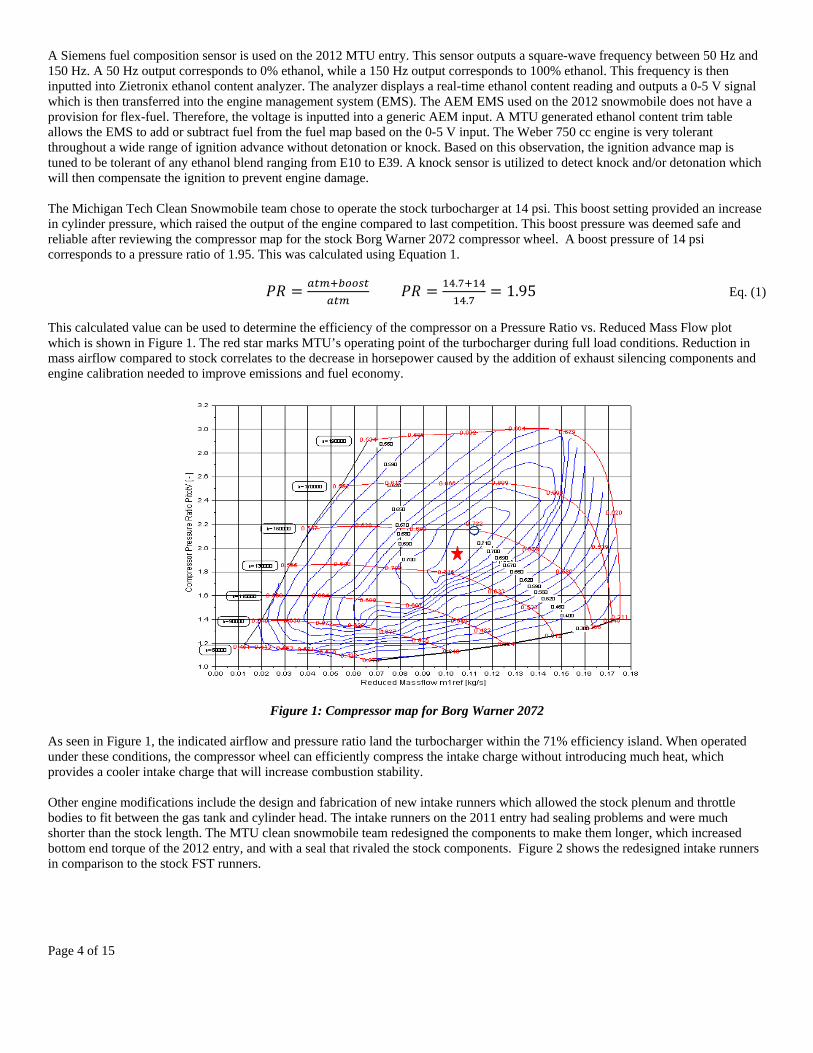
A Siemens fuel composition sensor is used on the 2012 MTU entry. This sensor outputs a square-wave frequency between 50 Hz and 150 Hz. A 50 Hz output corresponds to 0% ethanol, while a 150 Hz output corresponds to 100% ethanol. This frequency is then inputted into Zietronix ethanol content analyzer. The analyzer displays a real-time ethanol content reading and outputs a 0-5 V signal which is then transferred into the engine management system (EMS). The AEM EMS used on the 2012 snowmobile does not have a provision for flex-fuel. Therefore, the voltage is inputted into a generic AEM input. A MTU generated ethanol content trim table allows the EMS to add or subtract fuel from the fuel map based on the 0-5 V input. The Weber 750 cc engine is very tolerant throughout a wide range of ignition advance without detonation or knock. Based on this observation, the ignition advance map is tuned to be tolerant of any ethanol blend ranging from E10 to E39. A knock sensor is utilized to detect knock and/or detonation which will then compensate the ignition to prevent engine damage. The Michigan Tech Clean Snowmobile team chose to operate the stock turbocharger at 14 psi. This boost setting provided an increase in cylinder pressure, which raised the output of the engine compared to last competition. This boost pressure was deemed safe and reliable after reviewing the compressor map for the stock Borg Warner 2072 compressor wheel. A boost pressure of 14 psi corresponds to a pressure ratio of 1.95. This was calculated using Equation 1.
.
.1.95 Eq. (1)
This calculated value can be used to determine the efficiency of the compressor on a Pressure Ratio vs. Reduced Mass Flow plot which is shown in Figure 1. The red star marks MTU’s operating point of the turbocharger during full load conditions. Reduction in mass airflow compared to stock correlates to the decrease in horsepower caused by the addition of exhaust silencing components and engine calibration needed to improve emissions and fuel economy.
Figure 1: Compressor map for Borg Warner 2072 As seen in Figure 1, the indicated airflow and pressure ratio land the turbocharger within the 71% efficiency island. When operated under these conditions, the compressor wheel can efficiently compress the intake charge without introducing much heat, which provides a cooler intake charge that will increase combustion stability. Other engine modifications include the design and fabrication of new intake runners which allowed the stock plenum and throttle bodies to fit between the gas tank and cylinder head. The intake runners on the 2011 entry had sealing problems and were much shorter than the stock length. The MTU clean snowmobile team redesigned the components to make them longer, which increased bottom end torque of the 2012 entry, and with a seal that rivaled the stock components. Figure 2 shows the redesigned intake runners in comparison to the stock FST runners.

Page 5 of 15
Figure 2: Stock intake runners (left) and MTU designed intake runners (right)
CHARGING SYSTEM
Additional modifications were required in order to mount the MPE750 into the 2011 Switchback Assault chassis. In its stock configuration in the IQ chassis, the MPE750 is equipped with an automotive-style alternator in order to power the electrical system on the snowmobile as well as to charge the battery. However, due to space constraints, an alternator was not an option for the electrical system. Polaris personal watercrafts also use the MPE750 and in this configuration the alternator is replaced by a stator. The MTU clean snowmobile team has attempted using the stock Polaris watercraft stator on the MPE750 in years past but has found that in a snowmobile application, and with the electrical demands placed on the system, the stator wattage is not sufficient for sustained engine operation. However, for the 2011 IC entry, the stock Polaris stator has been replaced by a high output unit, from Watcon, designed for use with the MPE750. The stator is a prototype unit and is in development for high performance MPE750 applications. In addition to implementing the new high output stator, measures have been taken to reduce the electrical demands of the snowmobile for 2011. Further efforts to reduce the electrical demand placed on the snowmobile include the deletion of hand and thumb warmers as well as the use of more energy efficient and compact LED lighting for headlights and tail lights.
EMISSIONS
For 2012, a reduction in engine emissions from the 2011MTU entry was a main focal point. To achieve lower engine emissions, two critical paths were chosen. The first involved selecting a catalyst with increased efficiency. After selection of the correct catalyst, the engine management system allowed for precision control of both the fuel injection and ignition systems to achieve the lowest possible engine out emissions. To select the correct catalyst, emissions data collected by the MTU Clean Snowmobile Team on a dynamometer at selected rpm points was analyzed. Data was collected using an EMS model 5001 gas analyzer. Emissions samples from two new catalyst options were compared against the engine emissions output from the 3-way catalyst used on the 2011 MTU competition entry. The results can be seen in Figures 1-3.

Page 6 of 15
Figure 1: Engine Hydrocarbon (HC) output vs. RPM
Figure 2: Engine Carbon Monoxide (CO) output in percent vs. RPM
050
100150200250300350400450500
0 2000 4000 6000 8000
HC (ppm)
Engine RPM
Hydrocarbon Emissions
Catalyst A
Catalyst B
Catalyst C
0
1
2
3
4
5
6
0 2000 4000 6000 8000
CO %
Engine RPM
Carbon Monoxide Emissions
Catalyst A
Catalyst B
Catalyst C

Page 7 of 15
Figure 3: Engine Nitrogen Oxide output (NOx) vs. RPM
The Figures 1-3 shown above compare three different V-Converter catalysts at select RPM points. Catalyst A is a three pass catalyst while catalyst B and C are prototype single pass catalysts designed to target specific engine out emissions. It was found that the single pass catalyst C was the most effective for the Weber 750cc turbocharged engine.
By inspecting the emissions output plots of the three catalysts, the most effective catalyst was chosen. Catalyst C provided an average reduction of 79% HC and 23% CO %, although it caused an increase in NOx by a factor of 4. Despite the increase in NOx emissions, catalyst C was chosen for the large decreases in HC and CO emissions.
EXHAUST
Since the MTU clean snowmobile team has had success in the noise events in past competitions implementing a muffler and catalyst combination, the team again decided to design and fabricate a muffler and use the V-Converter catalyst selected through the emissions testing. After selecting the exhaust configuration to be used for the 2012 MTU IC entry, a list of critical design constraints were developed for the exhaust system. Table 4 below lists the major design constraints used for exhaust fabrication.
Table 4: List of critical exhaust design constraints
Exhaust Design Constraints
1 Package exhaust components
under/inside of stock hood and side panels
2 Exhaust must consist of a MTU designed two-chamber muffler
and catalyst
3 Exhaust must maintain a minimum of .25” from
all other parts
4 Design must account for heat
management and heat expulsion
5 Must not weigh more than 2011
MTU exhaust configuration After carefully considering the five critical design constraints, a two chamber muffler was designed with volumes of approximately 171 and 251 cubic inches in the first and second chambers, respectively. To determine the effectiveness of the muffler a transmission loss simulation was conducted using a Matlab generated code. A graph of the simulation results can be seen in Figure 4.
0
10
20
30
40
50
60
0 2000 4000 6000 8000
NOx (ppm)
Engine RPM
Nitrogen Oxide emissions
Catalyst A
Catalyst B
Catalyst C

Page 8 of 15
Figure 4: MTU Clean Snow 2012 muffler transmission loss
The simulation shows that the muffler will be effective throughout a wide range of frequencies. The two chamber design was selected and a final product was fabricated from 1020 mild steel. Figures 5 and 6 shows the final exhaust configuration implemented on the 2012 MTU entry.
Figure 5: MTU designed exhaust mounted in chassis Figure 6: Backside of MTU designed exhaust
The design features a post muffler catalyst. There was some concern of loose muffler packing blocking the catalyst during normal operation and the catalyst not reaching an optimum operating temperature to be effective, but durability and dynamometer testing of the exhaust configuration proved otherwise. The exhaust configuration is secured to the oxygen sensor housing by a ball joint to ensure minimal leakage and mounted to the chassis using rubber isolated mounts.
CHASSIS
The 2012 MTU entry is based on the 2011 Polaris Switchback Assault. The chassis offers several important advantages over other available chassis in the industry including weight reduction and improved rider ergonomics. The Polaris Pro-Ride chassis was never designed to accept the Weber MPE750 power plant. This required the creation of new engine mounts to cradle the engine in the cast magnesium bulkhead. The MTU engine mount system securely holds the engine in three locations including one main location on the power take off (PTO) side of the engine, and on two lower locations, front and rear on the stator side of the engine. The PTO engine

Page 9 of 15
mount has been computer numerical control (CNC) cut from aluminum and the stator side mounts have been CNC machined from billet aluminum, and all three have been fitted with vibration isolating bushings. The engine mounts can be seen in Figures 6-8.
Figure 6: PTO engine mount
Figure 7: Front stator side engine mount (left) next to stock mount (right)
Figure 8: Rear stator side engine mount
Page 10 of 15
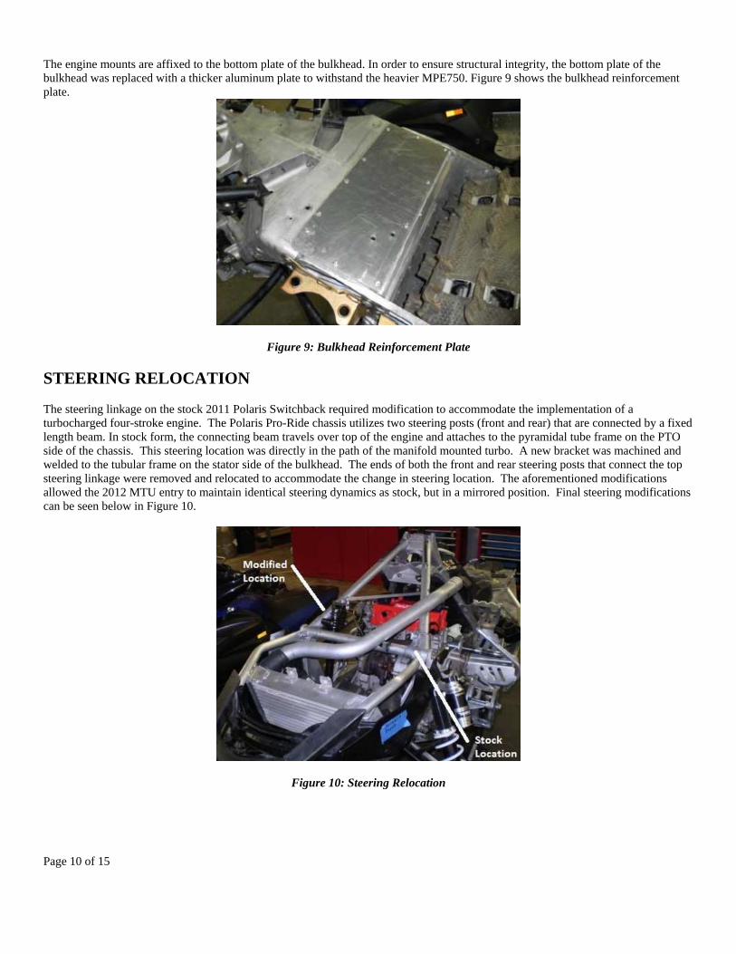
The engine mounts are affixed to the bottom plate of the bulkhead. In order to ensure structural integrity, the bottom plate of the bulkhead was replaced with a thicker aluminum plate to withstand the heavier MPE750. Figure 9 shows the bulkhead reinforcement plate.
Figure 9: Bulkhead Reinforcement Plate
STEERING RELOCATION
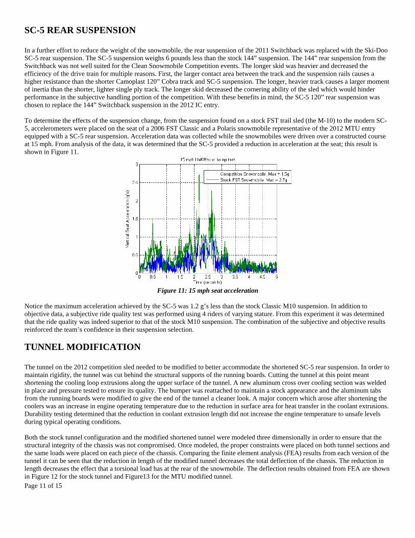
The steering linkage on the stock 2011 Polaris Switchback required modification to accommodate the implementation of a turbocharged four-stroke engine. The Polaris Pro-Ride chassis utilizes two steering posts (front and rear) that are connected by a fixed length beam. In stock form, the connecting beam travels over top of the engine and attaches to the pyramidal tube frame on the PTO side of the chassis. This steering location was directly in the path of the manifold mounted turbo. A new bracket was machined and welded to the tubular frame on the stator side of the bulkhead. The ends of both the front and rear steering posts that connect the top steering linkage were removed and relocated to accommodate the change in steering location. The aforementioned modifications allowed the 2012 MTU entry to maintain identical steering dynamics as stock, but in a mirrored position. Final steering modifications can be seen below in Figure 10.
Figure 10: Steering Relocation
Page 11 of 15
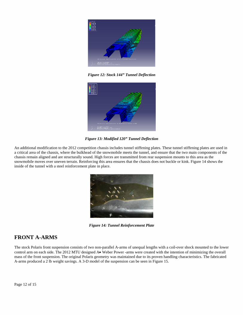
SC-5 REAR SUSPENSION In a further effort to reduce the weight of the snowmobile, the rear suspension of the 2011 Switchback was replaced with the Ski-Doo SC-5 rear suspension. The SC-5 suspension weighs 6 pounds less than the stock 144” suspension. The 144” rear suspension from the Switchback was not well suited for the Clean Snowmobile Competition events. The longer skid was heavier and decreased the efficiency of the drive train for multiple reasons. First, the larger contact area between the track and the suspension rails causes a higher resistance than the shorter Camoplast 120” Cobra track and SC-5 suspension. The longer, heavier track causes a larger moment of inertia than the shorter, lighter single ply track. The longer skid decreased the cornering ability of the sled which would hinder performance in the subjective handling portion of the competition. With these benefits in mind, the SC-5 120” rear suspension was chosen to replace the 144” Switchback suspension in the 2012 IC entry. To determine the effects of the suspension change, from the suspension found on a stock FST trail sled (the M-10) to the modern SC-5, accelerometers were placed on the seat of a 2006 FST Classic and a Polaris snowmobile representative of the 2012 MTU entry equipped with a SC-5 rear suspension. Acceleration data was collected while the snowmobiles were driven over a constructed course at 15 mph. From analysis of the data, it was determined that the SC-5 provided a reduction in acceleration at the seat; this result is shown in Figure 11.
Figure 11: 15 mph seat acceleration
Notice the maximum acceleration achieved by the SC-5 was 1.2 g’s less than the stock Classic M10 suspension. In addition to objective data, a subjective ride quality test was performed using 4 riders of varying stature. From this experiment it was determined that the ride quality was indeed superior to that of the stock M10 suspension. The combination of the subjective and objective results reinforced the team’s confidence in their suspension selection.
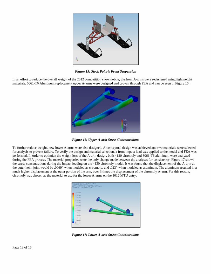
TUNNEL MODIFICATION The tunnel on the 2012 competition sled needed to be modified to better accommodate the shortened SC-5 rear suspension. In order to maintain rigidity, the tunnel was cut behind the structural supports of the running boards. Cutting the tunnel at this point meant shortening the cooling loop extrusions along the upper surface of the tunnel. A new aluminum cross over cooling section was welded in place and pressure tested to ensure its quality. The bumper was reattached to maintain a stock appearance and the aluminum tabs from the running boards were modified to give the end of the tunnel a cleaner look. A major concern which arose after shortening the coolers was an increase in engine operating temperature due to the reduction in surface area for heat transfer in the coolant extrusions. Durability testing determined that the reduction in coolant extrusion length did not increase the engine temperature to unsafe levels during typical operating conditions. Both the stock tunnel configuration and the modified shortened tunnel were modeled three dimensionally in order to ensure that the structural integrity of the chassis was not compromised. Once modeled, the proper constraints were placed on both tunnel sections and the same loads were placed on each piece of the chassis. Comparing the finite element analysis (FEA) results from each version of the tunnel it can be seen that the reduction in length of the modified tunnel decreases the total deflection of the chassis. The reduction in length decreases the effect that a torsional load has at the rear of the snowmobile. The deflection results obtained from FEA are shown in Figure 12 for the stock tunnel and Figure13 for the MTU modified tunnel.
Page 12 of 15
Figure 12: Stock 144” Tunnel Deflection
Figure 13: Modified 120” Tunnel Deflection An additional modification to the 2012 competition chassis includes tunnel stiffening plates. These tunnel stiffening plates are used in a critical area of the chassis, where the bulkhead of the snowmobile meets the tunnel, and ensure that the two main components of the chassis remain aligned and are structurally sound. High forces are transmitted from rear suspension mounts to this area as the snowmobile moves over uneven terrain. Reinforcing this area ensures that the chassis does not buckle or kink. Figure 14 shows the inside of the tunnel with a steel reinforcement plate in place.
Figure 14: Tunnel Reinforcement Plate
FRONT A-ARMS The stock Polaris front suspension consists of two non-parallel A-arms of unequal lengths with a coil-over shock mounted to the lower control arm on each side. The 2012 MTU designed AWeber Power -arms were created with the intention of minimizing the overall mass of the front suspension. The original Polaris geometry was maintained due to its proven handling characteristics. The fabricated A-arms produced a 2 lb weight savings. A 3-D model of the suspension can be seen in Figure 15.
Page 13 of 15
Figure 15: Stock Polaris Front Suspension In an effort to reduce the overall weight of the 2012 competition snowmobile, the front A-arms were redesigned using lightweight materials. 6061-T6 Aluminum replacement upper A-arms were designed and proven through FEA and can be seen in Figure 16.
Figure 16: Upper A-arm Stress Concentrations To further reduce weight, new lower A-arms were also designed. A conceptual design was achieved and two materials were selected for analysis to prevent failure. To verify the design and material selection, a front impact load was applied to the model and FEA was performed. In order to optimize the weight loss of the A-arm design, both 4130 chromoly and 6061-T6 aluminum were analyzed during the FEA process. The material properties were the only change made between the analyses for consistency. Figure 17 shows the stress concentrations during the impact loading on the 4130 chromoly model. It was found that the displacement of the A-arm at the outer heim joint would be .0069” when modeled as chromoly, and .023” when modeled as aluminum. The aluminum resulted in a much higher displacement at the outer portion of the arm, over 3 times the displacement of the chromoly A-arm. For this reason, chromoly was chosen as the material to use for the lower A-arms on the 2012 MTU entry.
Figure 17: Lower A-arm Stress Concentrations
Page 14 of 15
After construction of the A-arms for the 2012 snowmobile, the A-arms were installed and trail tested for roughly 100 miles before competition without any signs of failure. This included portions of un-groomed access trails as well as the local trail system.
COST In an effort to keep manufacturing costs as low as possible, every component added to the 2012 MTU IC entry was carefully analyzed. The benefits and costs associated with each additional component were scrutinized; the result was a realistic estimated MSRP of $12,576.95. When this estimated MSRP is compared to that of a 2012 Polaris Turbo IQ, which has an MSRP of $11.199.00 dollars, the additional cost is not substantial. Since the 2012 MTU IC entry includes advancements in both chassis and flex fuel technologies, weighs less, and produces significantly less emissions, the MTU Clean Snowmobile Team feels the additional $1377.95 is well justified.
CONCLUSION The 2012 MTU IC entry used state of the art chassis and suspension technology to reduce weight, increase drive efficiency, and improve rider ergonomics. Comprehensive data collection and analysis of exhaust systems for emissions after treatment as well as for noise reduction have been utilized in the selection of an exhaust system. Through utilization of standalone engine management, stock performance has been preserved while reducing noise and emissions. The 2012 MTU IC entry represents a first-of-its-kind engine and chassis combination which melds proven four-stroke emissions and noise characteristics with modern lightweight chassis technology.
ACKNOWLEDGMENTS Special thanks to all of the following sponsors for making it possible for the 2011 MTU CSC snowmobile to enter competition. 3M General Motors Polaris Ice Age Autodesk ArcelorMittal USA Chrysler LLC Cummins E3 Spark Plugs Ford Motor Company Fund Oshkosh Corporation John Deere Foundation DENSO Vconverter HMK TiAL Weber Power Weber Motor Arctic FX
REFERENCES
1. Blough, J. “Sound Basics as Applied to Snowmobiles” 2009. 2. Blough, J., Ball, J. Levine, J., Nagy, S., Rahman, D., Rittenour, M., Wichlacz, A., “Breaking Trail for Efficiency: Enhancing
the Polaris Switchback” 2010. 3. Blough, J., Anderson, C., Hetteen, A., Nasca, L., Rittenour, M., Schounard, K., Smiarowski, G., “Development of the Polaris
Switchback Assault: A Fusion of Advnaced Technology with Proven Reliability” 2011. 4. Heywood, John B. Internal Combustion Engine Fundamentals. New York: McGraw-Hill, 1988.
CONTACT INFORMATION
Dr. Jason R. Blough is an Associate Professor in the department of Mechanical Engineering at Michigan Technological University and the faculty advisor for both the MTU Clean Snowmobile Team and the SAE Student Chapter at Michigan Technological University. ME-EM Department Michigan Technological University 1400 Townsend Drive Houghton, MI 49931 Phone: (906) 487-1020 Email: [email protected]
Page 15 of 15
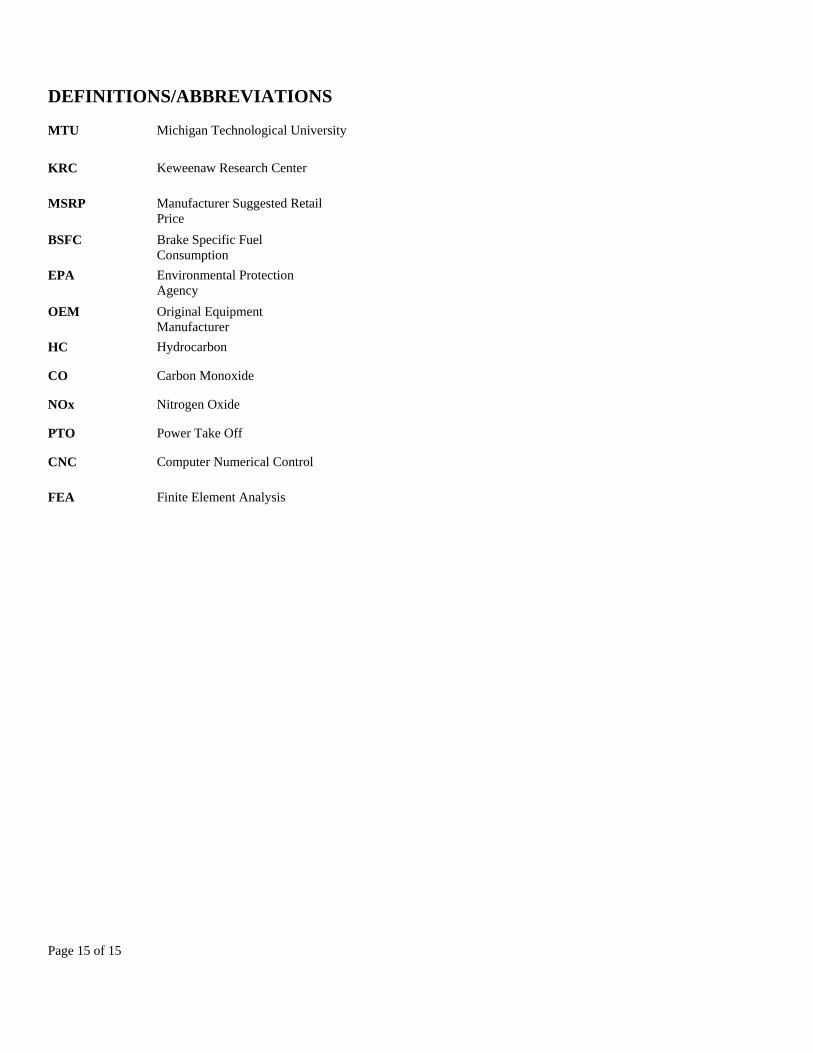
DEFINITIONS/ABBREVIATIONS
MTU
Michigan Technological University
KRC Keweenaw Research Center
MSRP Manufacturer Suggested Retail Price
BSFC Brake Specific Fuel Consumption
EPA Environmental Protection Agency
OEM Original Equipment Manufacturer
HC Hydrocarbon
CO Carbon Monoxide
NOx Nitrogen Oxide
PTO Power Take Off
CNC Computer Numerical Control
FEA Finite Element Analysis