
IMPROVED HYDROCARBON RECOVERY OF A LEAN RETROGRADE …utpedia.utp.edu.my/16862/1/Iqmal Irsyad...
61
IMPROVED HYDROCARBON RECOVERY OF A LEAN RETROGRADE GAS RESERVOIR UNDER PROPANE INJECTION By IQMAL IRSYAD BIN MOHAMMAD FUAD 14796 Dissertation submitted in partial fulfilment of The requirements for the Bachelor of Engineering (Hons) Petroleum JANUARY 2015 Universiti Teknologi PETRONAS Bandar Seri Iskandar 31750 Tronoh Perak Darul Ridzuan
Transcript of IMPROVED HYDROCARBON RECOVERY OF A LEAN RETROGRADE …utpedia.utp.edu.my/16862/1/Iqmal Irsyad...
IMPROVED HYDROCARBON RECOVERY OF A LEAN
RETROGRADE GAS RESERVOIR UNDER PROPANE
INJECTION
By
IQMAL IRSYAD BIN MOHAMMAD FUAD
14796
Dissertation submitted in partial fulfilment of
The requirements for the
Bachelor of Engineering (Hons) Petroleum
JANUARY 2015
Universiti Teknologi PETRONAS
Bandar Seri Iskandar
31750 Tronoh
Perak Darul Ridzuan

i
CERTIFICATION OF APPROVAL
Improved Hydrocarbon Recovery of a Lean Retrograde Gas Reservoir
under Propane Injection
By
Iqmal Irsyad Bin Mohammad Fuad
14796
A project dissertation submitted to the
Petroleum Engineering Programme
Universiti Teknologi PETRONAS
in partial fulfilment of the requirements for the
BACHELOR OF ENGINEERING (Hons)
(PETROLEUM)
Approved by,
_________________________
(MUHAMMAD ASLAM MD YUSOF)
UNIVERSITI TEKNOLOGI PETRONAS
TRONOH, PERAK
January 2015

ii
CERTIFICATION OF ORIGINALITY
This is to certify that I am responsible for the work submitted in this project, that the
original work is my own except as specified in the references and
acknowledgements, and that the original work contained herein have not been
undertaken or done by unspecified sources or persons.
_________________________________
(IQMAL IRSYAD BIN MOHAMMAD FUAD)
iii
ABSTRACT
In most cases, retrograde gas reservoir in N Field which is located at the north of
Malay Basin achieved 40-70% of recovery factor (RF) compared to dry gas
reservoir, 80-90% of RF. Reservoir K, a lean retrograde gas reservoir of the N Field
drained by Well 5 experience reduction in recovery (about 60% of RF) that is caused
by a significant productivity loss, suspected due to condensate banking effect.
Condensate banking phenomenon (observed as skin) around the perforation zone
restrict the flow of gas after the flowing bottom hole pressure falls below the dew
point pressure. Therefore, the reduction in gas Inflow Performance Relationship
(IPR) limits the Estimated Ultimate Recovery (EUR) of Reservoir K that is produced
from 2008 to 2013. Miscible propane stimulated injection is proposed at mid of 2012
(where skin start increasing) to improve the IPR, well deliverability and hence
reservoir recovery. The retrograde gas reservoir model is integrated between E300,
IPM PROSPER (well model) and IPM MBAL (reservoir model) software in
reservoir performance prediction and forecasting study. Results show that there is
4% increment in gas recovery and 6% increment in condensate recovery after
injection of propane to Reservoir K. There are about 4.2 million USD increment in
revenue upon propane injection development. As conclusion, propane injection could
minimize the condensate saturation that improves reservoir IPR and hydrocarbon
recovery for both gas and condensate.

iv
ACKNOWLEDGEMENTS
I would like to express my deepest appreciation to all those who supported,
believed, and provided me the possibility to complete this report. First of all, I would
like to thank my supportive supervisor, Mr. Muhammad Aslam Bin Md Yusof for his
guidance and advice throughout the completion of Final Year Project. The
supervision and encouragement are truly help the progression and smoothness in
completion of this project.
A special gratitude I give to my industrial supervisor, Mr. Awangku Alizul, a
reservoir engineer from Nippon Oil Exploration (Malaysia) Limited in assisting me
along this project period, guidance and providing direction that provide me
confidence in completing the project. His depth industry-technical knowledge helps
in sharpening my understanding especially in reservoir study.
I am also wanted to take this opportunity to extend the gratitude to Mr. Najib
Ramli, Reservoir Engineer from Talisman (Malaysia) Limited and Mrs. Mariam
Abdul Aziz, Principal Reservoir Engineer from Onyx IES Sdn Bhd in providing me a
non-stop guidance in reservoir engineering understanding. In addition, I would like
to thank Mr. Faiz H. Hussin, Director of Dyna Segmen Sdn Bhd who improve my
engineering senses and Mr. Muhammad Zuhaili Bin Kashim, graduate student for his
information and advices to proceed with the condensate reservoir study.
Not to forget my appreciation to my external examiners, lecturers, and
friends, your advices really motivated me.
Finally, I dedicated this dissertation work to my lovely family for their
understanding and trust me throughout the period of completing the project.
v
TABLE OF CONTENTS
CERTIFICATION OF APPROVAL ........................................................................................ i
CERTIFICATION OF ORIGINALITY .................................................................................. ii
ABSTRACT ............................................................................................................................ iii
ACKNOWLEDGEMENTS .................................................................................................... iv
TABLE OF CONTENTS................................................,.........................................................v
LIST OF FIGURES ............................................................................................................... vii
LIST OF TABLES.................................................................................................................viii
ABBREVIATIONS AND NOMENCLATURES ................................................................... 1
INTRODUCTION ................................................................................................................... 2
1.1 Background .................................................................................................................... 2
1.2 Problem Statement ......................................................................................................... 5
1.3 Objectives ...................................................................................................................... 6
1.4 Scope of Study ............................................................................................................... 7
LITERATURE REVIEW ........................................................................................................ 8
2.1 Retrograde Gas Reservoir .............................................................................................. 8
2.1.1 Composition of Retrograde/Condensate Fluid ...................................................... 11
2.1.2 Retrograde Gas Reservoir Performance ................................................................ 12
2.2 Condensate Banking .................................................................................................... 12
2.2.1 Flowing Bottom Hole Pressure Decline below the Dew Point Pressure ............... 13
2.2.2 Condensate Saturation Regions ............................................................................ 13
2.2.3 Gas Relative Permeability ..................................................................................... 14
2.3 Production Schemes: Well Stimulation Approach ....................................................... 15
2.3.1 Miscible Injection Approach ................................................................................. 16
2.3.1.1 Supercritical Carbon Dioxide Injection............................................................17
2.3.1.2 Carbon Dioxide Huff 'n' Puff Method..............................................................19
vi
2.3.1.3 Propane Injection..............................................................................................19
2.3.2 Chemical (Solvent) Treatment .............................................................................. 20
2.4 Compositional Modelling: Retrograde Gas Reservoir ................................................. 22
2.4.1 Mass Transport in Porous Media .......................................................................... 23
2.4.2 Conservation of Energy ........................................................................................ 24
2.4.3 Cubic Equation of State: Peng Robinson .............................................................. 25
METHODOLOGY ................................................................................................................ 28
3.1 Project Workflow ......................................................................................................... 28
3.1.1 Reservoir Candidate Selection .............................................................................. 29
3.1.2 Integrated Reservoir Modelling ............................................................................ 32
3.2 Project Gantt Chart and Key Milestone ....................................................................... 35
RESULT AND DISCUSSION .............................................................................................. 36
4.1 Effect of Propane Injection to Condensate Saturation and Reservoir Pressure ........... 36
4.2 Effect of Propane Injection to Inflow Performance Relationship (IPR) ...................... 39
4.3 Effect of Propane Injection to Reservoir K Recovery ................................................. 42
4.4 Quick Economic Evaluation ........................................................................................ 44
CONCLUSION & RECOMMENDATION .......................................................................... 47
5.1 Conclusion ................................................................................................................... 47
5.2 Recommendation ......................................................................................................... 47
REFERENCES ...................................................................................................................... 48

vii
LIST OF FIGURES
Figure 1: Location of the N Field in Malay Basin ................................................................... 3
Figure 2: Reservoir K performance and effect of condensate banking to gas deliverability
and production ......................................................................................................................... 5
Figure 3: Simulated Reservoir K model under natural depletion ............................................ 6
Figure 4: Phase Diagram of Retrograde Gas (McCain, 1990) ................................................. 9
Figure 5: Phase diagram of a Lean Gas Condensate Reservoir (Fan et al., 1998) ................. 10
Figure 6: Comparison between Rich Gas Condensate and Lean Gas Condensate liquid
dropout vs pressure (Fan et al., 1998) .................................................................................... 10
Figure 7: Ternary Diagram of gas mixture of Methane, Propane, and n-Pentane (McCain,
1990) ...................................................................................................................................... 11
Figure 8: Pressure vs distance of Retrograde Gas Reservoir liquid build up analysis ........... 14
Figure 9: Summary of applicable technique in mitigating condensate banking .................... 22
Figure 10: Final Year Project Workflow ............................................................................... 28
Figure 11: Well 5C (Reservoir K) Production Survey Data .................................................. 31
Figure 12: K Reservoir Pressure Survey Data ....................................................................... 31
Figure 13: Petrophysic Log Data of K Reservoir .................................................................. 32
Figure 14: History matched, simulated, and prediction of gas production from IPM MBAL 33
Figure 15: PI and skin throughout the time ............................................................................ 34
Figure 16: Condensate saturation result upon different rates of propane injection ............... 36
Figure 17: Effect of propane injection to reservoir pressure .................................................. 38
Figure 18: IPR Curve for March 2012 Model ........................................................................ 39
Figure 19: IPM MBAL results on average gas rate and cumulative gas production ............. 41
Figure 20: Cumulative Gas Production .................................................................................. 42
Figure 21: Cumulative Condensate Production ..................................................................... 43
Figure 22: Gas Oil Ratio (GOR) changes upon propane injection ........................................ 44
Figure 23: Quick Economic Evaluation ................................................................................. 45
Figure 24: Retrograde Gas Reservoir study area in hydrocarbon recovery project ............... 48

viii
LIST OF TABLES
Table 1: Reservoir Candidate Selection Criteria from N Field Reservoir Management
Review (FRMR 2013) of Gas Well Prioritization for Intervention Plan ............................... 30
Table 2: Reservoir input parameters ...................................................................................... 32
Table 3: Project Gantt Chart and Key Milestone ................................................................... 35

1
ABBREVIATIONS AND NOMENCLATURES
EUR Estimated Ultimate Recovery
RF Recovery Factor
IPR Inflow Performance Relationship
WOC Water- Oil-Contact
GOC Gas-Oil-Contact
CGR Condensate-Gas-Ratio
GIIP Gas-Initial-In-Place
FGOR Field-Gas-Oil Ratio
FGPT Field-Gas-Production Total
FOPT Field Oil Production Total
FOE Field Oil Recovery
Bscf Billion Standard Cubic Feet
MMscf Million Standard Cubic Feet
STB Stock Tank Barrel
IFT Interfacial Tension
FYP I Final Year Project 1
FYP II Final Year Project II

2
CHAPTER 1
INTRODUCTION
1.1 Background
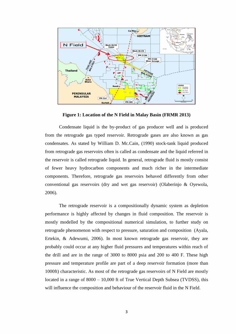
The N Field is located at the north of Malay Basin as shown in Figure 1.
Geologically, N Field consists of a series of low relief anticlines with enhanced
rollover features along a major system of northwest-southeast trending faults. The
reservoirs have similar stratigraphy to the neighbouring field and are Oligo-Miocene
in age and consist of fluvial to shallow water deltaic sandstones, which vary greatly
in thickness and areal distribution. In addition, the N Field is still a Green Field and
predominantly a Gas Development Field currently undergo production to re-
development phase of petroleum life cycle. The gross gas production of the N Field
is approximately 400MMscf/D (depend on market demand) with averaged 5000
STB/D of condensate liquid (by-product) that contribute about 28% of the N Field
net liquid production. The condensate liquid production gives a lot of impact to the
net liquid production of N Field. Therefore, a strategic production development of
gas wells in N Field is crucial in optimizing production of not only to the gas, but
also condensate liquid.
3
Figure 1: Location of the N Field in Malay Basin (FRMR 2013)
Condensate liquid is the by-product of gas producer well and is produced
from the retrograde gas typed reservoir. Retrograde gases are also known as gas
condensates. As stated by William D. Mc.Cain, (1990) stock-tank liquid produced
from retrograde gas reservoirs often is called as condensate and the liquid referred in
the reservoir is called retrograde liquid. In general, retrograde fluid is mostly consist
of fewer heavy hydrocarbon components and much richer in the intermediate
components. Therefore, retrograde gas reservoirs behaved differently from other
conventional gas reservoirs (dry and wet gas reservoir) (Olaberinjo & Oyewola,
2006).
The retrograde reservoir is a compositionally dynamic system as depletion
performance is highly affected by changes in fluid composition. The reservoir is
mostly modelled by the compositional numerical simulation, to further study on
retrograde phenomenon with respect to pressure, saturation and composition (Ayala,
Ertekin, & Adewumi, 2006). In most known retrograde gas reservoir, they are
probably could occur at any higher fluid pressures and temperatures within reach of
the drill and are in the range of 3000 to 8000 psia and 200 to 400 F. These high
pressure and temperature profile are part of a deep reservoir formation (more than
1000ft) characteristic. As most of the retrograde gas reservoirs of N Field are mostly
located in a range of 8000 – 10,000 ft of True Vertical Depth Subsea (TVDSS), this
will influence the composition and behaviour of the reservoir fluid in the N Field.

4
In most production cases of the retrograde gas reservoir, the pressure falls
below the dew point within a short production period, increases the saturation of
retrograde fluid (condensate blockage) around the wellbore that cause loss in
productivity (Thomas, Andersen, & Bennion, 2009). They also added that the
phenomenon cause reduction in the permeability around the perforated zone, thus
limit the gas deliverability. This reduction in productivity is observed as skin where
skin is an unknown reduction or increment in productivity during production
operation. Based on this complex phenomenon, a lot of studies have been
approached to study on the best method in enhancing the hydrocarbon recovery,
theoretically by reducing the skin such as gas cycling, hydraulic fracturing,
horizontal well, acidizing, and chemical treatment.
The project focuses on Reservoir K study to represent the retrograde reservoir
performance in the N field. Reservoir K is selected based on selection criteria from
the industry Field Reservoir Management Review (FRMR 2013) report in gas well
prioritization for intervention program. Reservoir K starts producing in 2008 and had
been depleted and abandoned in 2013 due to low productivity of the well which is
not economic to keep producing that zone. Poor performance of Reservoir K was
investigated and most of Reservoir K field data had been utilized to develop a
simulation approach study of retrograde gas reservoir performance. Reservoir K is
drained by gas producer, Well 5C for about 5 years of production under natural
depletion and recovers approximately 60-70% of recovery factor. A study on
Reservoir K was conducted and engineers found out that condensate banking
phenomenon is one of the main factor to the retrograde gas recovery problem of the
Reservoir K.
1.2 Problem Statement
Gas wells producing with high condensate gas ratio (CGR) reservoir zone
decline in productivity when the bottom hole flowing pressure drops below the dew
point pressure of the liquid. The condensate liquid banking around the perforation
zone restricts the flow of gas and affects the gas Inflow Performance Relationship

5
(IPR). Reduction in gas IPR (reservoir potential) lower the well productivity or
known as gas well deliverability.
According to the field experience, poor management of retrograde gas
reservoir could cause reduction in hydrocarbon recovery. Figure 2 shows Reservoir
K performance, presenting the reservoir pressure depletion trend (at bottom) and
production history profile with deliverability curve trend. It is observed that decline
in productivity starts at the mid of 2012 (circle in red). This period was investigated
by deliverability curve analysis from IPM PROSPER model. In the deliverability
curve, high skin value alters the shape of the curve that shows reduction in well
productivity. Based on previous study, Reservoir K skin value has a range of 30 – 90
from the mid of 2012 onward that reduce the productivity index (PI). Petrowiki
source summarized that the decline in productivity index observed in many fields is
by a factor 2 to 4 because of liquid build-up. This skin increment may due to micro-
scale reservoir effect (2 phase fluid flow challenges) such as capillary forces,
interfacial tension (IFT), and relative permeability.
Figure 2: Reservoir K performance and effect of condensate banking to gas
deliverability and production (FRMR 2013)
The reduction in well deliverability represents poor performance IPR at the
bottom hole. This reduction in gas IPR limits the Estimated Ultimate Recovery
(EUR) and hence lowering the hydrocarbon recovery (Al-Shawaf, Kelkar, & Sharifi,
2013). Figure 3 proves low gas recovery of Reservoir K which EUR is about 16.88
Bscf and RF of 73% from 22.87 Bscf of Gas-Initial-In-Place (GIIP).

6
Figure 3: Simulated Reservoir K model under natural depletion (FRMR 2013)
Figure 3 also demonstrates a history matched performance with actual
Reservoir K performance. Based on the study, Reservoir K recovers 73% of gas
recovery factor that is lower than other conventional gas reservoir. Low gas recovery
of Reservoir K is due to productivity loss once Reservoir K faced two phase fluid
flow into the wellbore. This will limit the EUR and hence gas recovery. As the
condensate is the by-product of the gas reservoir, low gas recovery also would affect
the condensate recovery.
1.3 Objectives
Based on Reservoir K analysis and available field data, the objectives of the
study are mainly;
To study the effect of propane injection to reservoir IPR and hydrocarbon
recovery that include both gas and condensate liquid (by-product)
To propose propane injection (stimulation approach) as part of retrograde
gas reservoir development in N Field by preparing Reservoir K study

7
1.4 Scope of Study
There are two main analysis in this study which are study on Reservoir K
under actual/natural depletion performance (base case) and under propane injection
development at proposed date. The timeframe of both analysis are the same which is
within the actual production performance of Reservoir K from 2008 to 2013.
Study was limited to availability of actual field data that cover only macro-
scale analysis. In addition, reservoir and well model was integrated by using
compositional Eclipse model E300, IPM PROSPER, and IPM MBAL software due
to geology model and micro-scale laboratory data limitation. Therefore, there are
several assumptions and limitations being set depend on subsurface data quality and
availability;
A homogeneous and isotropy single tank reservoir with history matched
properties (not considering the geologic geometry of the reservoir)
Isothermal reservoir system
The zone produce at a high rate (>10MMscf/D – abandonment rate),
therefore capillary pressure is set as zero (neglected)
Assume an ideal completion set up and hence Non-Darcy flow is neglected
No/minor water production
Gravity effect is neglected
Dispersive flux is neglected
In an isothermal system, the molar energy is also could be neglected

8
CHAPTER 2
LITERATURE REVIEW
This chapter presents critical review of the literature as the conceptual
guideline for Retrograde Gas Reservoir K study and technical analysis. The main
focus of the study would be emphasis on the phase and flow behaviour, deliverability
and performance, and condensate banking phenomena of the Retrograde Gas
Reservoir K in understanding of the reservoir complex system.
2.1 Retrograde Gas Reservoir
During the discovery phase, retrograde gas reservoirs are mostly found
consist of a single-phase gas vapor (based on the ―butterfly effect‖ in the well log).
Upon production phase, condensate liquid could be observed at the surface. The
retrograde gas reservoir could be characterized as the transition between volatile oil
and wet gas reservoir with having a critical temperature less than reservoir
temperature and a cricondentherm greater than reservoir temperature (Dumkwu,
2013). These behaviour are the effect of retrograde gases consist of small amount of
heavy (long-chain) hydrocarbon than the crude oils (McCain, 1990). Figure 4 shows
the phase diagram of retrograde gas reservoir where liquid condensate was developed
upon isothermal depletion (Grigg & Lingane, 1983). In contrast, dry gas and wet
gases do not undergo phase changes upon reservoir depletion, as their phase
envelope‘s cricondentherm are found to the left of the reservoir temperature isobar
line (Ayala et al., 2006).

9
Figure 4: Phase Diagram of Retrograde Gas (McCain, 1990)
The gas condensate is usually light-coloured (straw colour), more volatile
than crude oil, compose a huge portion of gasoline and other volatile petroleum
components, and typically consist API gravity of above 50 degrees (Thornton, 1946).
In addition, a rich retrograde gas can produce gas-oil ratio (GOR) of 3300 to 5000
scf/STB initially. These characteristics and behaviours are crucial to be studied and
understand on the complex system behaviour that could effect on later production
performance.
Based on the Reservoir K Drill Stem Tester (DST) evaluation, the fluid
composed 46.63 API and GOR range from 45000 to 65000 scf/STB during the
exploration phase. Based on Kamath in 2007, Reservoir K fluid could be categorized
as a lean condensate gas since the CGR is ranged between 15-22 bbl/MMscf (lower
than 100 bbl/MMscf) and is in between the wet gas reservoir and rich retrograde gas
reservoir characteristic. Figure 5 shows the phase diagram for a lean gas condensate
and the comparison between the rich and lean retrograde reservoir could be observed
in Figure 6 to see the different in liquid drop out versus pressure.

10
Figure 5: Phase diagram of a Lean Gas Condensate Reservoir (Fan et al., 1998)
Figure 6: Comparison between Rich Gas Condensate and Lean Gas Condensate
liquid dropout vs pressure (Fan et al., 1998)

11
2.1.1 Composition of Retrograde/Condensate Fluid
The composition indices for retrograde gas systems are the gas-liquid ratio
(GLR) of produced fluids (could also indicate as gas-oil ratio, GOR or condensate-
gas ratio, (CGR) (Moses and Donohoe ,1987). However, the knowledge of the gas-
liquid ratio and gravity of the liquid in not enough to describe the composition of gas
condensate for all purposes, since the gas-liquid ratio and the gravity of condensate
are functions of the pressure and temperature at which the separation are made
(Thornton, 1946). Therefore, it is important to represent the fluid composition in
fraction or percentage in every state of fluid (gas, condensate, and gas-condensate
mixture) (Dumkwu, 2013).
Methane and ethane with few quantities of propane, butanes, pentanes,
hexanes, and heptane plus is mostly composed in gas produced from retrograde gas
reservoir. While the heptane and heavier fractions, with reducing fraction of hexanes,
pentanes, butanes, and fewer amounts of propane, ethane, and methane are composed
in the condensate fluid (Dumkwu, 2013).
As the phase diagram depends on fluid composition, the ternary diagram
concept for more than one component in a mixture is used in developing the
petroleum mixture diagram as shown in Figure 7. The compositional phase diagram
for three component mixture plotted in terms of mole fraction/percentage. The
ternary diagram is mostly used in analysis of miscible displacement (McCain, 1990).
Figure 7: Ternary Diagram of gas mixture of Methane, Propane, and n-Pentane
(McCain, 1990)
12
2.1.2 Retrograde Gas Reservoir Performance
In this part, retrograde gas reservoir performance of Reservoir K will be
discussed to study the effect of condensate banking to reservoir performance.
Reservoir K could be classified as a lean gas condensate as it generates small volume
of the liquid phase (typically less than 100bbl per million ft3) compared to a rich gas
condensate (generally more than 150bbl per million ft3). The production of Reservoir
K by pressure depletion method results in low recovery (approximately 60-70%) of
the gas-initially-in-place (GIIP) especially the liquid phase. This supported by
(Kolbikov, 2010), where for a typical retrograde gas reservoir, 85% of the dry gas-in-
place is normally recovered, while 40-70% of original condensate element of the gas
is remain in the reservoir due to retrograde condensation. He added that the
hydrocarbon recovery factor of retrograde gas reservoir do rely on the initial gas-oil
ratio (GOR), filtration properties, well spacing, and completion, development plan,
economical indexes, and abandon reservoir pressure.
At reservoir pressure above the dew point pressure, the gas deliverability rely
on the reservoir thickness, permeability, and viscosity (Lal, 2003). While at pressure
below the dew point, the gas deliverability is controlled by the critical condensate
saturation and the shape of the gas and condensate relative permeability curves.
However, Dumkwu (2013) stated that for a lean retrograde gas reservoir, the
cumulative production is mainly caused by pressure gradient and not by high relative
permeability reduction. Other factors that might reduce the well deliverability are
non-Darcy flow, critical condensate saturation, and high capillary number effects
(Hashemi, Nicolas, & Gringarten, 2006).
2.2 Condensate Banking
Condensate banking phenomenon is the main problem in managing the
retrograde gas reservoir that engineers need to understand on its dynamic system.
Retrograde gas reservoirs are normally single-phase gas at discovery and the initial
reservoir pressure is above or close to the critical pressure. Once production is
initiated, isothermal pressure decline and at the saturation pressure (dew point
pressure), retrograde liquid saturation start to build up near the perforated zone due

13
to drawdown below the dew point pressure, that restrict the flow of gas (A. S. Al-
Abri, 2011; Fan et al., 1998). Fan et al. (1998) also conclude that the phenomenon is
caused by fluid phase properties, formation flow characteristic and pressure in the
formation and in the wellbore.
2.2.1 Flowing Bottom Hole Pressure Decline below the Dew Point Pressure
Upon gas production, the flowing bottom hole pressure (FBHP) falls below
the dew point within short period of the production. Therefore, saturation condensate
build up around the wellbore area and create the condensate bank as stated by Sayed
and Al-Muntasheri in 2014. This may affect the well deliverability loss for both gas
and condensate for more than 50% based on the industry literature (Kamath , 2007).
Even in lean gas condensate reservoirs, where the maximum liquid dropout in the
constant composition expansion (CCE) experiment is low as 1%, the condensate
liquid build up close the wellbore may effect a significant reduction in productivity
(Al-Shawaf et al., 2013).
2.2.2 Condensate Saturation Regions
The condensate saturation region ranges in size from tens of feet for lean
condensates to hundreds of feet for rich condensates depend on the volume of gas
being drained and the percentage of liquid dropout (directly proportional) (A. S. Al-
Abri, 2011).
Theoretically, flow in retrograde gas reservoir could be divided into three
reservoir regions with different liquid saturation (Gringarten, Al-Lamki, Daungkaew,
Mott, & Whittle, 2000). These regions are shown in Figure 8 as follows:
Region 3: Far from the production wells and the pressure is above the dew
point pressure. Therefore, there is single gas phase present.
Region 2: A rapid increase in liquid saturation and corresponding reduction in
gas relative permeability. The trapped condensate liquid in the small pore
cause the capillary forces act on it, those make them difficult to flow.

14
Region 1: Close to the wellbore where condensate saturation reaches a critical
value. That cause two-phase flow in porous medium.
Figure 8: Pressure vs distance of Retrograde Gas Reservoir liquid build up
analysis
2.2.3 Gas Relative Permeability
The amount of liquid phase saturated rely not only on the pressure,
temperature, and composition, but also on the fluid properties and relative
permeability (Hinchman & Barree, 1985; Sognesand, 1991). Upon pressure
depletion, high amount of liquid can be condensed, resulting in high liquid
saturations in the formation pores (Moses and Donohoe , 1987). Therefore, the
possibility of hydrocarbon fluid to flow through and out of the reservoir should be
examined. They also recommend that the combination of relative permeability
relationship (Krg/Kro vs. saturation) and viscosity data (µo/µg) could be used in the
volumetric proportion of liquid (in the flowing stream) estimation that would also
affect the remaining reservoir phase compositions at every stage of pressure
depletion. The condensate build up near the wellbore not only reduces the
productivity of condensate, but also reduce the gas effective relative permeability
with consequent reduction in well deliverability of gas at surface facilities (Dumkwu,
2013). This phenomenon could be observed as the skin in reduction of well
deliverability.

15
2.3 Production Schemes: Well Stimulation Approach
After the dynamic behaviour of retrograde gas reservoir and the mechanism
of condensate banking effect have been studied, an appropriate production schemes
can be investigated. The methods such as gas cycling, drilling horizontal wells,
hydraulic fracturing, injection of super critical CO2, huff ‗n‘ puff gas injection, use
of solvents, and the use of wettability alteration chemicals have been widely studied
to mitigate condensate banking problem (Sayed and Al-Muntasheri , 2014). In this
part, latest technologies and methods in mitigating condensate banking will be
reviewed and one method will be selected to be applied in Reservoir K. Each method
has their pros and cons under certain field application. In N Field, well stimulation
techniques will be prioritized as the technique improves well performance from
drainage area into the wellbore (around the perforated zone) that require a well
intervention program. Well stimulation technique does not require to drill additional
well that is suitable to be applied in multi stake reservoir development.
The horizontal wells and hydraulic fracturing both are effectively improve the
flow area and thus production rates. However, the limitation of hydraulic fracturing
is the well with bottom water. In 2011, France‘s constitutional court upheld a ban on
hydraulic fracturing, ruling that the law against the energy-exploration techniques
that brings consequences to the environment. Plus, condensate liquid will still builds
up around fractured well or horizontal wells although it takes a longer time for the
bank to form. The benefit also must be compared to increased cost. Thus, this study
will focus in stimulating well around the perforated zone instead of drilling other
additional producer/injection well.
There are several stimulation techniques would be discussed in this section
for Reservoir K case study, depending on the cost, solution availability, and political
issues. Thornton (1946) stated the basic principles in field particular operating
method selection as follows;
Selection of operating method on the basis of reservoir fluid character
Pressure maintenance in those reservoir where a decrease would result in loss
of valuable products at the surface
Efficient handling of produced fluids at the surface to extract the maximum
amount of liquid

16
Optimum spacing of wells to ensure maximum highest hydrocarbon recovery
Unitization of interest to assure equity to all parties with vested interests in
the reservoirs, and to enable the application of the afore-mentioned principles
Well stimulation processes could divide into two parts which are miscible gas
and chemical approach. Both processes is discussed and compared in simulation
study on which approach require minimum volume to be injected in order to dissolve
the condensate bank.
2.3.1 Miscible Injection Approach
The gas flooding method normally can be achieved by two process, miscible
or immiscible based on minimum miscibility pressure (MMP) (Ghedan, 2009). At
constant temperature and composition, MMP is the least pressure at which first or
multiple contact miscibility can be achieved. Miscible flooding is more efficient and
common in Enhanced Oil Recovery, EOR application, yet immiscible flooding may
become important where the reservoir conditions are not suitable for miscible
flooding. Immiscible process is one method to assist in maintaining the reservoir
pressure. Sometime, additional injector well also is required which means add
another additional cost of drilling a well.
Gas Cycling is one of the techniques applied by the industry for a long time
and provides an immiscible approach. The main objective of gas cycling approach is
to maintain the reservoir pressure above the dew point pressure that keep the fluid in
gas phase and prevent more condensation to formed at the same time (Sayed and Al-
Muntasheri ,2014). The stripped gas is compressed and re-injected into the reservoir
through the injection wells to displace further wet gas and keep the reservoir pressure
in minimizing the retrograde condensation (Dumkwu, 2013). However, sweep
efficiencies (both areal and vertical) and re-vaporization of the formed liquid
condensate bank may reduce the effectiveness of this method (Havlena, Griffith, Pot,
& Kiel, 1967). Plus, from the operational perspective, the profit from gas sales is
deferred and requires big initial capital expenditure for compression and injection.
Gas cycling allows the pressure to be maintained above the dew point but may not be
economical, especially late in the life of the reservoir when large quantities of

17
injected gas are required to maintain the pressure above dew point. In this part,
miscible process will be further discussed; (1) the techniques of super critical CO2
injection, (2) CO2 huff ‗n‘ puff method, and (3) Propane injection.
2.3.1.1 Super Critical Carbon Dioxide Injection
The N field produces approximately 20–30% of carbon dioxide from gross
gas production that makes engineer start to consider carbon dioxide injection into
depleted gas reservoirs. Carbon dioxide could be utilized for the field use application
in this hydrocarbon recovery effort. This method also is a good practice to store
carbon dioxide, instead of released to the atmosphere (Oldenburg and Benson ,2002).
The carbon dioxide injection capable to reduce the dew-point pressure of oil and gas
system (U. O. ODI, 2013). Plus, Mamora and Seo (2002) found that carbon dioxide
improve sweep efficiency and re-pressurization of depleted gas fields, in a laboratory
study to displace methane in a carbonate rocks. Lino (2000) performed an
experiment approach study and concludes that the carbon dioxide was the only
solvent that developed miscibility by vaporization of rich gas condensate mechanism.
On the other hand, Monger and Khakoo (1981) also noted that carbon dioxide
capable to reduce the miscibility pressure for paraffin fluids and enhance miscibility
mechanism of carbon dioxide injection. Thus, these show some of benefit of carbon
dioxide as the injection agent to provide miscibility mechanism.
The condensate liquid recovery also can be enhanced with carbon dioxide
injection in the depleted retrograde reservoirs (Jessen & Orr, 2004). In the other
study, Seto, Jessen, and Orr (2007) stated that the factors that affect the recovery
efficiency of carbon dioxide injection are local displacement efficiency, that is
controlled by phase behaviour of fluids mixture in the reservoir and the fluid flow at
which controlled by the reservoir heterogeneities.
The injection of supercritical carbon dioxide could improve the relative
permeability to gas and enhanced the recovery of the condensate liquids (A. Al-Abri
& Amin, 2010). They also found that the capacity (volume injected before
breakthrough take place) of supercritical carbon dioxide was 62% of PV compared to
methanol-supercritical carbon dioxide mixture (55% PV) and methane only (27%
18
PV). A modelling approach of a different scenarios comparative study of methane
injection, nitrogen injection, gas recycling, and carbon dioxide injection by Moradi,
Tangsiri Fard, Rasaei, Momeni, and Bagheri (2010) figure out that ability of carbon
dioxide injection recovered more liquid and gas than other scenarios. In a laboratory
scale study, Gachuz-Muro, Gonzalez Valtierra, Luna, and Aguilar Lopez (2011)
showed that carbon dioxide achieved higher recovery factor than nitrogen but less
than natural gas in a study to evaluate the effectiveness of gases in displacing
condensate from the reservoirs. Soroush, Hoier, and Kleppe (2012) investigate the
injection of carbon dioxide, methane, and mixture of methane and carbon dioxide in
dipping gas condensate reservoir for enhance condensate liquid recovery. Based on
the findings, the carbon dioxide injection attained the highest recoveries than other
injections. Another numerical simulation study of Kurdi, Xiao, and Liu (2012) on the
effect of super critical carbon dioxide injection, resulting that the method increases
the density of gas, decrease the viscosity, and density of condensate and lowers the
surface tension between the two phases that lowering the capillary pressure. Thus,
the condensate liquid recovery is improved with reducing the residual (critical)
condensate saturation.
Numerical simulation study conducted by Taheri, Hoier, and Torsaeter
(2013), investigate the miscible and immiscible gas injection performance in
condensate banking elimination process for a fractured gas condensate reservoirs.
Gases such as carbon dioxide, methane, and nitrogen are tested in the study. As the
result, carbon dioxide able to lowered the minimum miscibility pressure (MMP) and
hence recover more condensate liquid. Zaitsev et al. (1996) also conclude that carbon
dioxide flooding is one of the effective methods for removing the condensate plug.
However, the challenges of implementing carbon dioxide injection are carbon
dioxide is easily to react with produced water that could cause corrosion and make
the application is costly and risky. Surface facilities need to be enhanced to
implement this approach. Therefore an appropriate plan should be strategized in
order to embark the carbon dioxide injection method to K Reservoir.
19
2.3.1.2 Carbon Dioxide Huff ‘n’ Puff Method
Other technique of carbon dioxide injection is the huff ‗n‘ puff method which
uses the same producer well as injector well alternatively. Ahmed, Evans, Kwan, and
Vivian (1998) investigated the performance of lean gas, nitrogen, and carbon dioxide
huff ‗n‘ puff method in condensate liquid elimination near the wellbore. They found
that pure carbon dioxide is the most effective gas in minimizing the condensate
liquid dropout than the other gases at the same pressure system. The huff ‗n‘ puff
injection of gases also able to enhance the condensate liquid recovery by reducing
near wellbore damage due to condensate blocking.
U. Odi (2012) also studied the performance of carbon dioxide huff ‗n‘ puff
approach to eliminate gas-condensate around the wellbore. The method approaches
miscibility between the displacing natural gas and condensate by decreasing the dew
point pressure of the fluid mixture. He also found that the ability of carbon dioxide to
diffuse into the retrograde phase as the concentration of the carbon dioxide is
increased. However, the method is very sensitive to time once the process is executed
that should take consideration in field application.
2.3.1.3 Propane Injection
Propane injection is among the new technology had been approached and
studied in recovering a heavy oil reservoir. Yarranton, Badamchi-Zadeh, Satyro, and
Maini (2008) conducted a study on Anthabasca bitumen by diluting the bitumen
using propane and carbon dioxide to reduce the fluid viscosity, so that the fluid is
mobile enough to be drained. Plus, they found out that propane and butane have
higher solubility and provide greater viscosity reduction than carbon dioxide.
An experimental study by Ferguson, Mamora, and Goite (2001) on the
effectiveness of steam-propane injection in heavy oil recovery found out that the
light components of the hydrocarbon are miscible with the injected propane gas and
‗carried‘ by the propane ahead of the steam front. The miscibility mechanism
provides a no ‗boundary‘ between the fluid (heavy and lighter components) lower the
viscosity and hence accelerate the oil production. Study in mobilizing the heavy oil

20
could be used to recover the immobilize condensate near well-bore of gas well
producer.
Jamaluddin, Thomas, D‘Cruz, Nighswander, and Oilphase (2001) assess the
condensate behaviour near-wellbore zone by adding light hydrocarbon gases which
is propane in their study. The vaporization of condensate liquid capable to improves
the liquid extraction of gas producer well. The use of propane alters the system
conditions to be in supercritical conditions for most typical reservoir fluids at
reservoir pressure and temperature. Plus, the CCE test by Jamaluddin et al. (2001)
shows propane decrease both dew point pressure and total liquid dropout. Author
believes that propane as the vaporizer agent potential to improve the gas producer
well productivity.
The investigation of propane gas as the vaporizer agent could be further study
as propane potential to:
Dilute (miscible) the condensate liquid
Reduce condensate viscosity and hence mobility
Improve gas relative permeability and hence productivity
Decrease the dew point pressure of the hydrocarbon mixture
2.3.2 Chemical (Solvent) Treatment
Another possible approach than miscible injection is the chemical or solvent
treatment. This method apply injection of high molecular weight alcohols, such as
methanol, other mutual solvents, and surfactant to reduce the interfacial tension of
the immobilize condensate liquid and reservoir gas that enhance recovery of the
residual condensate (Dumkwu, 2013). In addition, the gas relative permeability can
also be increased from the alcohols and solvents treatment (Sayed and Al-Muntasheri
, 2014). They added that the mechanism of increased gas relative permeability from
solvent treatment could be presented into two ways which are the solvent able to
minimize the interfacial tension between the condensate and gas and solvent able to
dissolve some of the condensate into the gas stream.
21
A lot of literature studies on chemical (solvent) treatment effectiveness to
enhance the hydrocarbon recovery of retrograde gas reservoir system by reducing the
impairment effects of condensate build up near the wellbore (Kamath ,2007). For
example methanol application could enhance productivity but it does not give a long-
term effect because the condensate liquid will reform back upon reservoir depletion.
Du, Walker, Pope, Sharma, and Wang (2000) and Al-Anazi, Al-Otaibi, Al-
Faifi, and Hilab studied the application of methanol to treat damage caused by
condensate and water plugging. The authors presented that the condensate
precipitation could be delayed from the methanol injection by improving the gas-oil
relative permeability (achieved 1.2 to 2.5 times increase in the endpoints of gas
relative permeability). Plus, the methanol treatments eliminate both water and
condensate by a multi-contact miscible displacement if enough methanol are
injected. Bang, Pope, and Sharma (2006) also stated that the condensate liquid drop
out could be retarded by reducing the dew point pressure from the methanol
treatment to the mixture of water and condensate. Methanol treatments resulted in a
significant but temporary enhancement in productivity.
It is found that a lot of alcohol have sludge and emulsion problems with
condensates; hence, it is recommended to apply compatibility test between the
suggested injection alcohols and reservoir condensate before embarking the project
(Dumkwu, 2013). He also added that in most cases, the real reduction in condensate-
gas interfacial tension is relatively small, and hence, the stimulating effect might be
somehow insignificant.
Another study by Sayed and Al-Muntasheri (2014), summarized that
isopropyl alcohol (IPA) and methanol mixture could be an effective technique to
eliminate the condensate liquid and water bank near the wellbore in carbonate
reservoirs, as well as sandstone reservoirs. Although this technique is not last for a
long period (liquid can be accumulated again), but by a well-organized scheduling of
the well treatment activity could be an effective technique to be implemented.
However, chemical/solvent treatment is more recommended to be applied in rich
retrograde gas reservoir that having high CGR content and water production
problem. This is due to the high cost of chemical to be prepared in a huge (field)
22
scale. Economic wise, costly chemical is worth to recover the valuable high
condensate content in gas reservoir.
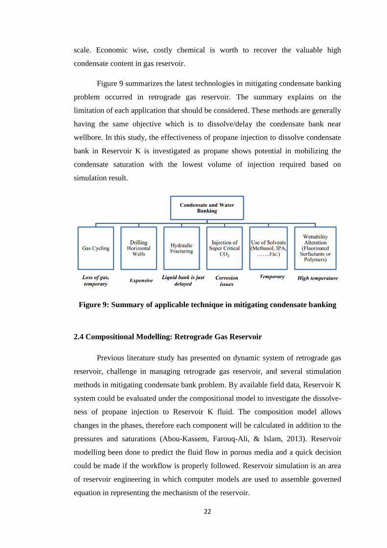
Figure 9 summarizes the latest technologies in mitigating condensate banking
problem occurred in retrograde gas reservoir. The summary explains on the
limitation of each application that should be considered. These methods are generally
having the same objective which is to dissolve/delay the condensate bank near
wellbore. In this study, the effectiveness of propane injection to dissolve condensate
bank in Reservoir K is investigated as propane shows potential in mobilizing the
condensate saturation with the lowest volume of injection required based on
simulation result.
Figure 9: Summary of applicable technique in mitigating condensate banking
2.4 Compositional Modelling: Retrograde Gas Reservoir
Previous literature study has presented on dynamic system of retrograde gas
reservoir, challenge in managing retrograde gas reservoir, and several stimulation
methods in mitigating condensate bank problem. By available field data, Reservoir K
system could be evaluated under the compositional model to investigate the dissolve-
ness of propane injection to Reservoir K fluid. The composition model allows
changes in the phases, therefore each component will be calculated in addition to the
pressures and saturations (Abou-Kassem, Farouq-Ali, & Islam, 2013). Reservoir
modelling been done to predict the fluid flow in porous media and a quick decision
could be made if the workflow is properly followed. Reservoir simulation is an area
of reservoir engineering in which computer models are used to assemble governed
equation in representing the mechanism of the reservoir.
23
Mathematical description of the compositional model for the fluid flow and
heat transfer in a permeable medium is obtained from:
Conservation of mass
Conservation of momentum
Conservation of energy
Equation of state and constitutive equations
The governing equation of the compositional model is essential to be
understood as they relate the phase behaviour to fluid flow and material balance
concept. This concept could describe on the relationship between IPR and
hydrocarbon recovery.
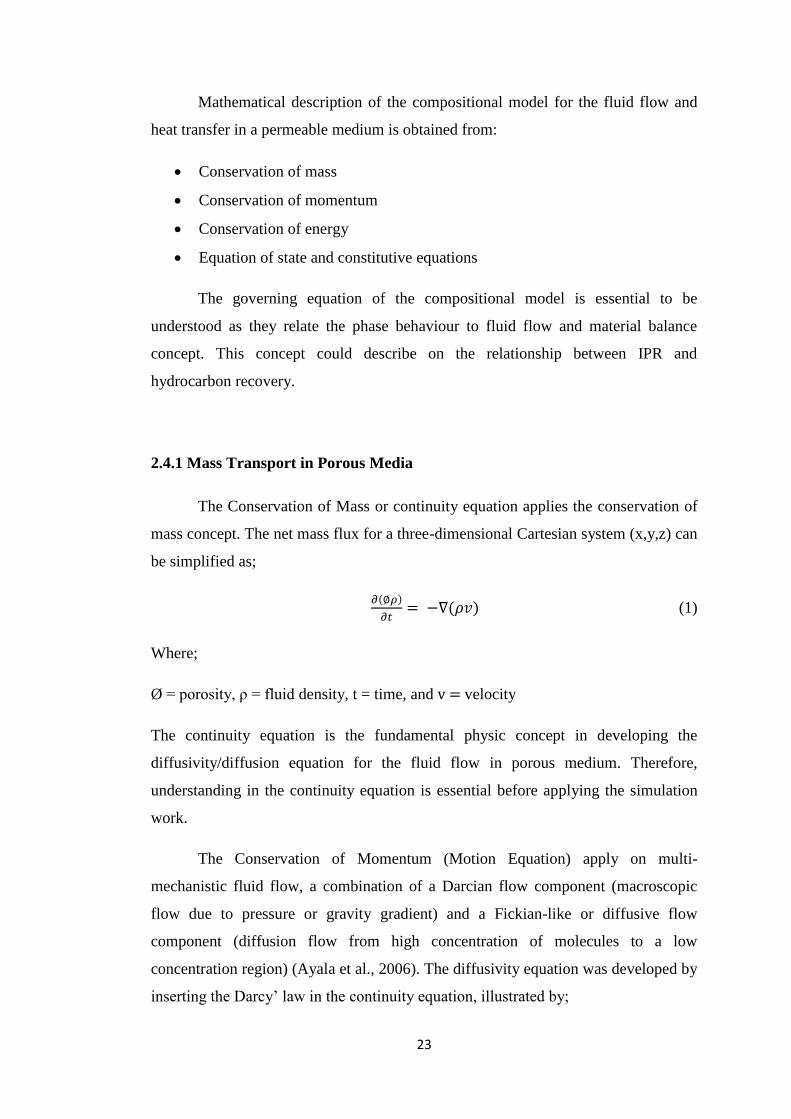
2.4.1 Mass Transport in Porous Media
The Conservation of Mass or continuity equation applies the conservation of
mass concept. The net mass flux for a three-dimensional Cartesian system (x,y,z) can
be simplified as;
( )
( ) (1)
Where;
Ø = porosity, ρ = fluid density, t = time, and v = velocity
The continuity equation is the fundamental physic concept in developing the
diffusivity/diffusion equation for the fluid flow in porous medium. Therefore,
understanding in the continuity equation is essential before applying the simulation
work.
The Conservation of Momentum (Motion Equation) apply on multi-
mechanistic fluid flow, a combination of a Darcian flow component (macroscopic
flow due to pressure or gravity gradient) and a Fickian-like or diffusive flow
component (diffusion flow from high concentration of molecules to a low
concentration region) (Ayala et al., 2006). The diffusivity equation was developed by
inserting the Darcy‘ law in the continuity equation, illustrated by;

24
(2)
Where;
P = pressure, t = time, = porosity, = viscosity, ct = total compressibility, and k =
permeability
Ayala et al. (2006) assumed that the multi-mechanistic phenomenon only take
place in the gas phase, while the flow of the liquid phase is only due to pressure
gradient. For the diffusion equation (developed from Fick‘s law and continuity
equation) can be shown as;
(3)
Where;
= porosity, t = time, D = diffusion coefficient and x = distance
The combination of both mass balance and motion equation result in mass transport
equation. This reservoir pressure-rate behaviour of an individual well also could be
known as reservoir inflow performance (IPR). The governed equation is the basic of
fluid flow equation in porous media as the equation also has been used in the Black
Oil Simulator (E100). As the compositional simulator (E300) is considering the fluid
phase behaviour, component, and thermodynamic parameters, additional equation of
state (EOS) algorithm is inserted in the mass transport equation.
2.4.2 Conservation of Energy
The first law of thermodynamic states that energy is conserved and neither
created nor destroyed and it is only transferred and converted to other types of
energy. The laws of conservation of energy for an arbitrary volume of the reservoir
fluid indicate that:
“Flux of energy through the boundary of an arbitrary volume + Energy input from
a source = Gain in internal energy”
25
The arbitrary volume may be considered as an infinitesimal rectangular
parallelepiped of lengths dx, dy and dz along x-, y-, and z- axis in a Cartesian
coordinate system. The total energy, transferring through the representative
elementary volume (REV) boundaries, consists of:
1. A part that is transferred through the mass transfer, convective term;
2. A part due to the heat transferred by conduction and radiation; and
3. The shear work, due to viscous stresses, occurs at the boundaries of the REV
This study focus on the miscible mechanism in an isothermal reservoir system
and thus, this equation could be neglected and is recommended to be investigated in
future work.
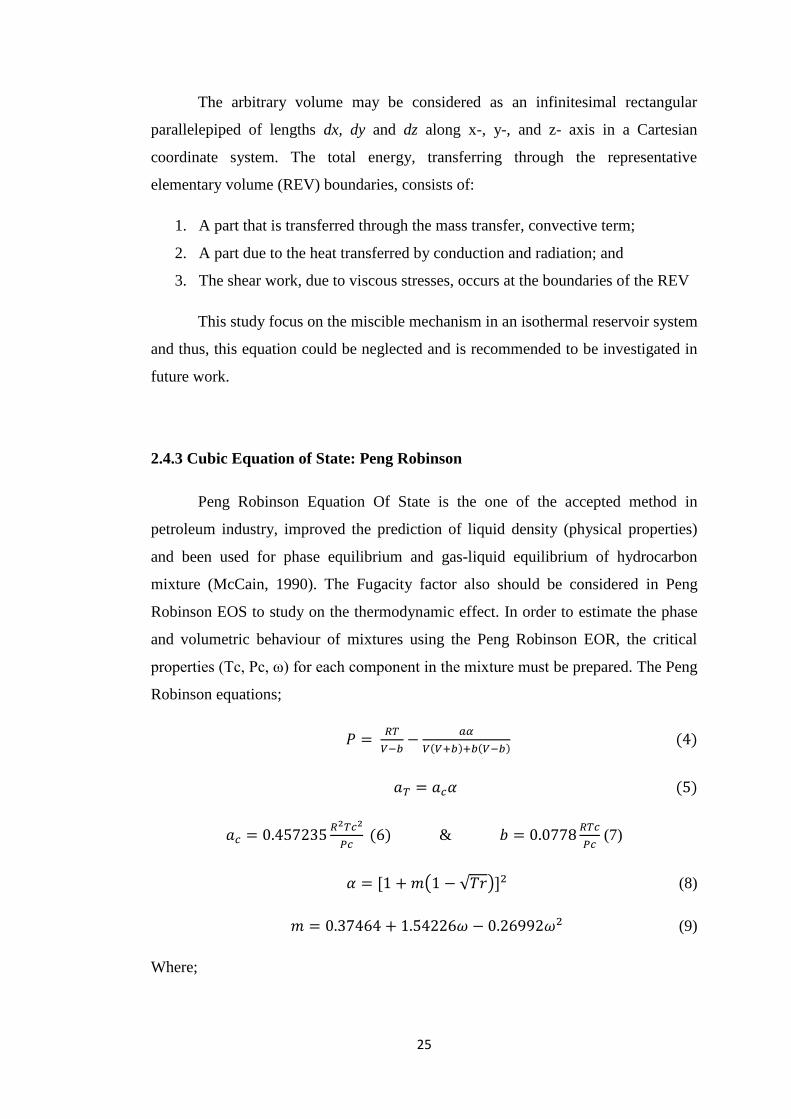
2.4.3 Cubic Equation of State: Peng Robinson
Peng Robinson Equation Of State is the one of the accepted method in
petroleum industry, improved the prediction of liquid density (physical properties)
and been used for phase equilibrium and gas-liquid equilibrium of hydrocarbon
mixture (McCain, 1990). The Fugacity factor also should be considered in Peng
Robinson EOS to study on the thermodynamic effect. In order to estimate the phase
and volumetric behaviour of mixtures using the Peng Robinson EOR, the critical
properties (Tc, Pc, ω) for each component in the mixture must be prepared. The Peng
Robinson equations;
( ) ( ) (4)
( )
( ) &
(7)
( √ ) (8)
(9)
Where;

26
P = pressure, R = universal gas constant, T = temperature, V = Volume, a = internal
pressure term, b = co-volume term, = temperature dependent parameter, aT =
dependent a term to temperature, ac = aT at critical temperature, and = Pitzer
accentric factor
The Peng-Robinson EOS was developed to simulate the depletion process,
characterize the fluid from well data and predict the reservoir behaviour upon the
isothermal depletion. After EOS has been tuned in phase diagram development of the
fluid, the model could be used for further fluid analysis study such as gas liquid
equilibrium, fluid properties, and phase stability study.
Gas Liquid Equilibrium is the area bounded by the bubble point and dew
point curve on the phase diagram of a multicomponent mixture define the conditions
for gas and liquid to exist in equilibrium (McCain, 1990). McCain also added that the
quantities and composition of the two phases varies different points within the limits
of the phase envelope. Gas liquid equilibrium is generally a condition in which a
liquid and its vapor are in equilibrium with each other. The equilibrium gas liquid
distribution ratio (K-value) is the ratio of composition in the vapor phase to that of
the liquid phase, developed from the combination of Raolt‘s and Dalton‘s law;
(10)
Where;
yj = mole fraction of jth
component in the gas, xj = mole fraction of jth
component in
the liquid, Pvj = vapor pressure of component jth
, and P = pressure
Since Raolt‘s and Dalton‘s law is only applicable for ideal solution, K-value
needs to be correlated in gas liquid equilibrium calculation for the industry practice
where hydrocarbon mixtures are mostly having non-ideal solution behaviour. The
most widely used empirical correlation for K-value estimation is Wilson‘s
correlation (Mohammed S.A., Cairo U., and Wattenbarger R.A., 1991). They also
found that the equation correlates pressure, temperature, critical properties, and
acentric factors of the system into a simple expression for K-values. Other than K-
value correlation, EOS also could be used to calculate gas liquid equilibrium as

27
alternative (McCain, 1990). He added that the main use of equilibrium ratios is to
predict compositional changes in the reservoir fluids where the K-value is the
function of pressure, temperature, and composition.
In this study, Peng Robinson Equation of State model had been used in
Eclipse E300, IPM PROSPER, and IPM MBAL software for fluid characterization
and PVT model. This model would describe fluid behaviour of Reservoir K upon
production of Well 5C.
Based on the governed equation, the EOS could be relates to the algorithm of
compositional simulation;
( ) ( ) (11)
Where,
&
And Ø = porosity, Sj = Phase j saturation, ρj = Phase j density, xij = mole fraction of
component i in phase j.
This equation describes each component flow mechanism correspond to the
phases. This fundamental equation is then been further developed to predict changes
of reservoir pressure, saturation, and compositions. As propane intermediate
component is injected to the condensate liquid which is mostly heavy component,
propane dilute the mixture and fluid flow performance would be close to single phase
fluid flow performance. This shows on how the fluid phase behaviour would affect
the fluid flow performance. The algorithm of the compositional simulator could
describe on how the propane affect the fluid behaviour by lowering the dew point
once propane dissolved in Reservoir K fluid that contribute to a better performance
in fluid flow after condensate liquid is mobilized and relative permeability is altered.
28
CHAPTER 3
METHODOLOGY
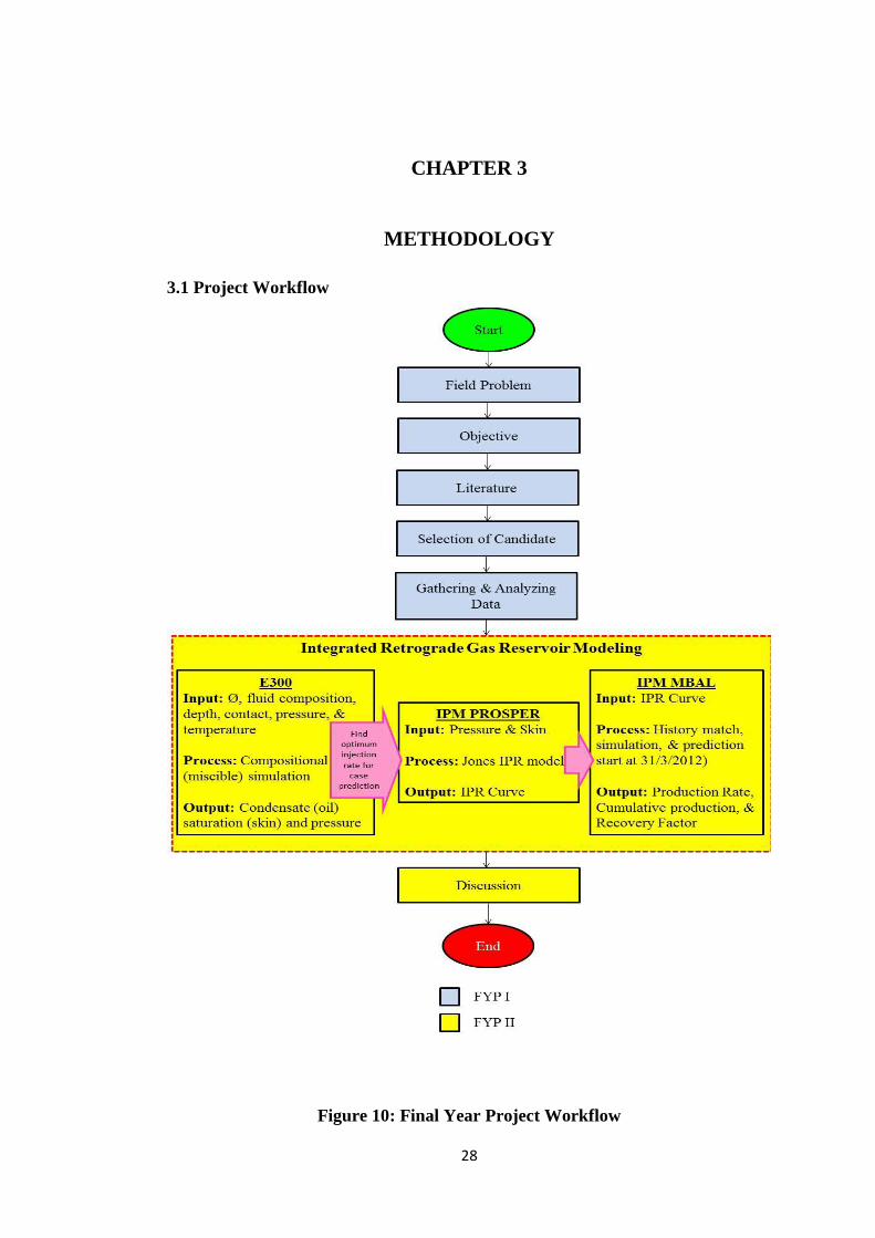
3.1 Project Workflow
Figure 10: Final Year Project Workflow

29
The project workflow above in Figure 10 presents the overview of FYP
methodology. The study is developed from problem faced in managing retrograde
gas reservoir during field experience. Therefore, the case study is selected and been
developed in order to investigate a more economical production scheme in producing
retrograde gas reservoir. Literature study is conducted to obtain the idea and
understand the complex mechanism of the reservoir and get updated with latest
technology been approached in mitigating the problem. The literature review are
mainly focusing on:
Understanding complex mechanism of retrograde gas reservoir
Understand typical problem in managing retrograde gas reservoir; condensate
banking phenomenon
Review of updated technology approached by the industry and evaluate the
advantages and limitation of different production scheme (focus on well
stimulation approach)
Investigate capability of propane injection
3.1.1 Reservoir Candidate Selection
In order to improve the hydrocarbon recovery in N Field, K Reservoir is
selected to be the candidate/representative of retrograde gas reservoir of N Field.
There are several criteria evaluated in selection of the retrograde gas reservoir which
are:
Reservoir consist of more than 10 stb/MMscf condensate gas ratio (CGR)
Moderate to good reservoir permeability (k>100mD)
Surface composition data availability
Single layer reservoir (Not commingle and no production allocation issue)
No/minor water production
The criteria are determined from typical characteristic of retrograde gas reservoir that
suspected facing condensate banking phenomenon referred to the N Field Reservoir
Management Review (FRMR 2013) report. And for simplicity, single layer and
reservoir with no water production is selected. As shown in Table 1, K Reservoir was
selected to be evaluated in order to study the best strategy of producing that zone.

30
Table 1: Reservoir Candidate Selection Criteria from N Field Reservoir
Management Review (FRMR 2013) of Gas Well Prioritization for Intervention
Plan
After candidate selection, Reservoir K field data was gathered and initial
analysis was conducted. Data also had been checked to eliminate outliers and this
process required experience judgement in selecting representative reservoir data.
From this process also, assumptions could be made and need to be clearly justified.
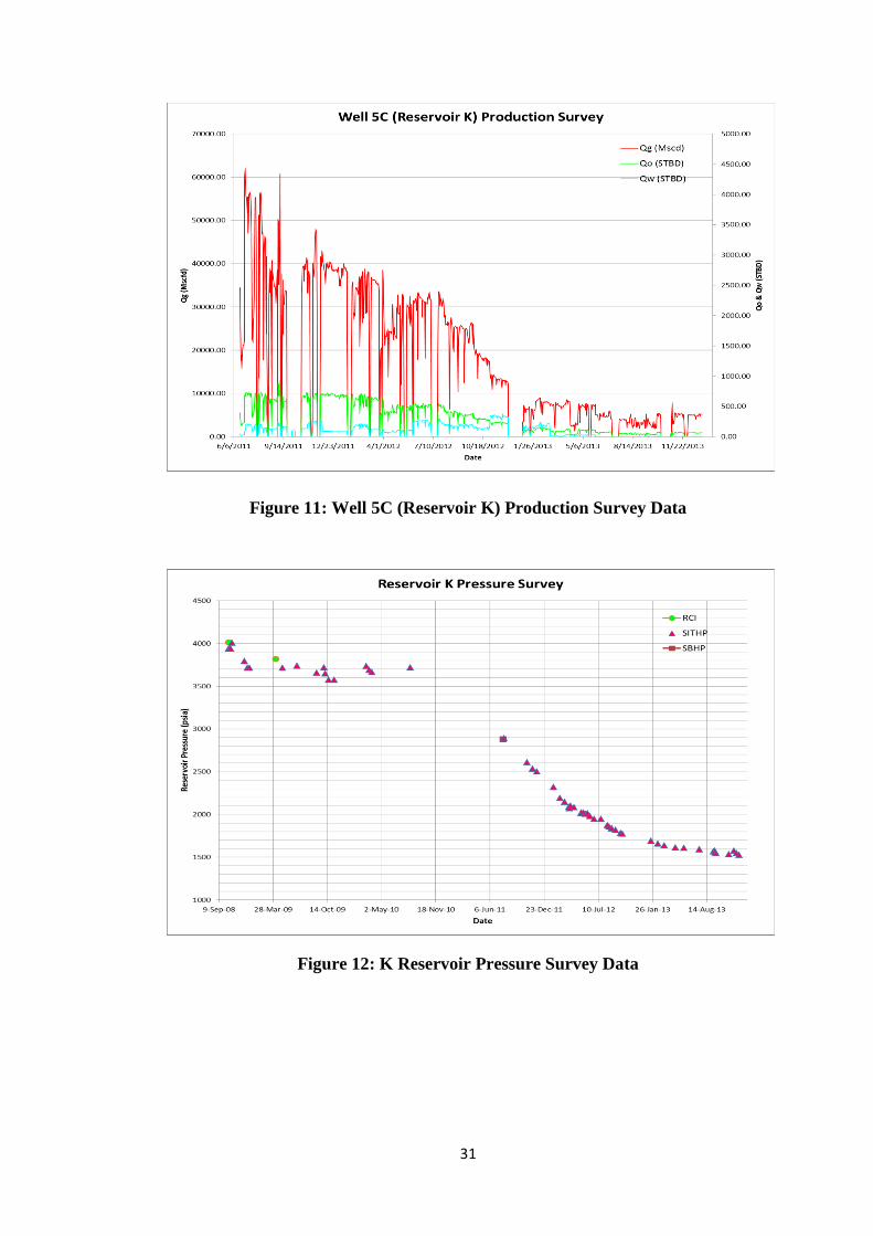
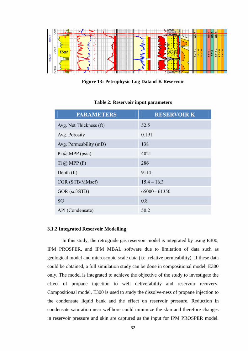
Available field data provided for the composition model study are:
Production History Data (shown in Figure 11)
Pressure Survey Data (shown in Figure 12)
Production Rate Test (Well Test) Data
Surface Composition Data
Petrophysic Log Data (shown in Figure 13)
Drill Stem Test Data
Fluid Properties Correlation Data
And the field data of Reservoir K had been compiled as in Table 2. Compiled
reservoir parameters presented both the rock and fluid properties of Reservoir K at a
field scale measurement. The table data are then used as the main input for all the
integrated software.
31
Figure 11: Well 5C (Reservoir K) Production Survey Data
Figure 12: K Reservoir Pressure Survey Data
32
Figure 13: Petrophysic Log Data of K Reservoir
Table 2: Reservoir input parameters
PARAMETERS RESERVOIR K
Avg. Net Thickness (ft) 52.5
Avg. Porosity 0.191
Avg. Permeability (mD) 138
Pi @ MPP (psia) 4021
Ti @ MPP (F) 286
Depth (ft) 9114
CGR (STB/MMscf) 15.4 – 16.3
GOR (scf/STB) 65000 - 61350
SG 0.8
API (Condensate) 50.2
3.1.2 Integrated Reservoir Modelling
In this study, the retrograde gas reservoir model is integrated by using E300,
IPM PROSPER, and IPM MBAL software due to limitation of data such as
geological model and microscopic scale data (i.e. relative permeability). If these data
could be obtained, a full simulation study can be done in compositional model, E300
only. The model is integrated to achieve the objective of the study to investigate the
effect of propane injection to well deliverability and reservoir recovery.
Compositional model, E300 is used to study the dissolve-ness of propane injection to
the condensate liquid bank and the effect on reservoir pressure. Reduction in
condensate saturation near wellbore could minimize the skin and therefore changes
in reservoir pressure and skin are captured as the input for IPM PROSPER model.

33
SPE 12778 is used and modified to represent the actual rock and fluid properties of
Reservoir K. The parameters changed are;
1. Porosity
2. Fluid composition
3. Reservoir Pressure and Temperature
4. Depth
5. Fluid contacts
IPM PROSPER model been used to develop well model of Well 5C. Plus, the
model has been matched with actual production rate test result to represent the actual
well performance. Jones IPR model was used in IPM PROSPER since the main input
required are reservoir pressure and skin to construct the IPR curve.
The IPR curve from the IPM PROSPER is then been used to IPM MBAL for
production forecasting. But first, the IPM MBAL model needs to be history match to
represent actual reservoir performance. Simulated (calculate from IPM MBAL based
on input data) output need to be calibrated with the actual measured result as shown
in Figure 14. After the model has been matched, cases prediction could be proceed
with different IPR curves.
Figure 14: History matched, simulated, and prediction of gas production from
IPM MBAL
34
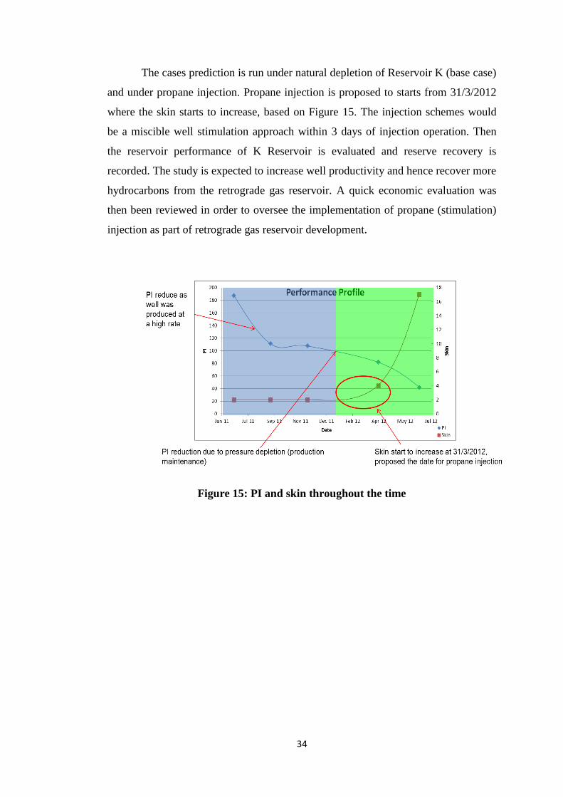
The cases prediction is run under natural depletion of Reservoir K (base case)
and under propane injection. Propane injection is proposed to starts from 31/3/2012
where the skin starts to increase, based on Figure 15. The injection schemes would
be a miscible well stimulation approach within 3 days of injection operation. Then
the reservoir performance of K Reservoir is evaluated and reserve recovery is
recorded. The study is expected to increase well productivity and hence recover more
hydrocarbons from the retrograde gas reservoir. A quick economic evaluation was
then been reviewed in order to oversee the implementation of propane (stimulation)
injection as part of retrograde gas reservoir development.
Figure 15: PI and skin throughout the time

35
3.2 Project Gantt Chart and Key Milestone
Table 3: Project Gantt Chart and Key Milestone
1 2 3 4 5 6 7 8 9 10 11 12 13 14 15 16 17 18 19 20 21 22 23 24 25 26 27 28
Identify Field Problem
Preliminary Research Work:> Retrograde Gas Reservoir> Condensate Banking> Well Stimulation Techniques> Compositional ModelingReservoir Candidate Selection:
> Data Gathering
> Initial Analysis
Modeling Work:
1. E300 - Compositional Simulation
2. IPM PROSPER - Well Model
3. IPM MBAL - Reservoir Model
Assess Stimulation Technique:
> Propane injection date
> Propane injection rate
Result and Discussion
Quick Economic Evaluation
Interim Report Submission
Progress Report
Pre-SEDEX
Dissertation Submission
Final Viva Presentation
FYP Activities
Process
Project Milestone
ActivitiesFYP 1 (Week) FYP 2 (Week)

36
CHAPTER 4
RESULT AND DISCUSSION
This project aims to mitigate lean retrograde gas reservoir recovery problem
of Reservoir K by proposing propane injection to increase reservoir pressure and
reduce skin (condensate saturation near wellbore). The effect of propane injection to
inflow performance relationship, IPR and it‘s improvement to reservoir recovery also
are the main focus in this chapter.
4.1 Effect of Propane Injection to Condensate Saturation and Reservoir
Pressure
The effect of propane injection to condensate saturation and reservoir
pressure was investigated by using E300 software in order to study the dissolve-ness
of injected propane to the condensate liquid bank near wellbore. Figure 16 shows on
different propane injection rates affect the condensate saturation for the next 3 years;
Figure 16: Condensate saturation result upon different rates of propane
injection
37
Based on the propane injection rates sensitivities study, it could be observed
that 207 Mscf/day of propane injection minimizes the condensate saturation for next
3 years. Therefore, 207 Mscf/day had been selected as the optimum rate to be
injected in Reservoir K. Changes to condensate saturation and reservoir pressure had
been captured to be the input for IPM PROSPER model. In this case, increase in the
skin factor of Reservoir K is suspected mainly from the condensate bank effect.
Therefore, it could be assumed that the skin in which inhibits gas deliverability had
been reduced for approximately another three years of production with 207 Mscf/day
of propane injection.
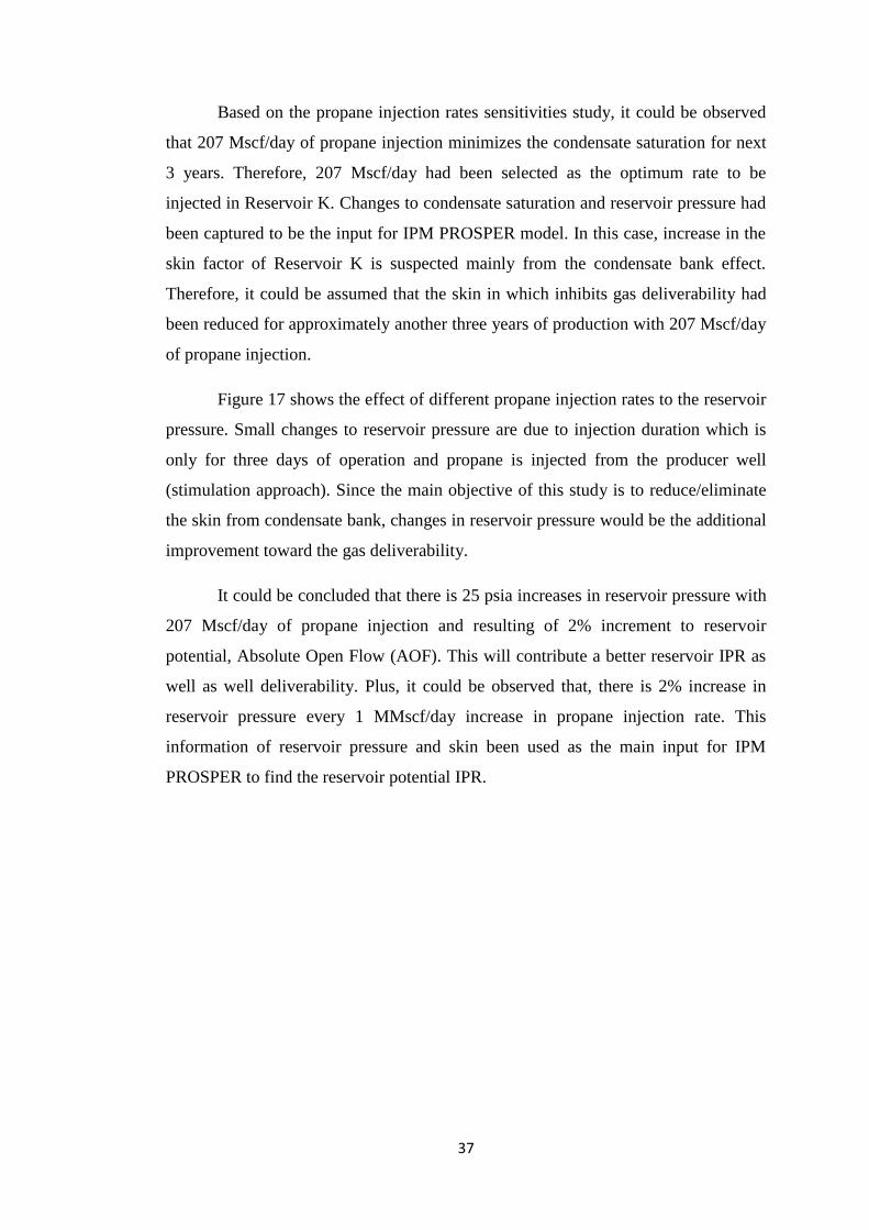
Figure 17 shows the effect of different propane injection rates to the reservoir
pressure. Small changes to reservoir pressure are due to injection duration which is
only for three days of operation and propane is injected from the producer well
(stimulation approach). Since the main objective of this study is to reduce/eliminate
the skin from condensate bank, changes in reservoir pressure would be the additional
improvement toward the gas deliverability.
It could be concluded that there is 25 psia increases in reservoir pressure with
207 Mscf/day of propane injection and resulting of 2% increment to reservoir
potential, Absolute Open Flow (AOF). This will contribute a better reservoir IPR as
well as well deliverability. Plus, it could be observed that, there is 2% increase in
reservoir pressure every 1 MMscf/day increase in propane injection rate. This
information of reservoir pressure and skin been used as the main input for IPM
PROSPER to find the reservoir potential IPR.
38
Figure 17: Effect of propane injection to reservoir pressure
The dissolve-ness of propane injection to condensate liquid of Reservoir K
results a dilute mixture that having a lower viscosity and hence increase the
condensate mobility. Propane as an intermediate components present in the injected
gas condense with condensate bank, heavier component in reservoir to generate a
modified fluid that become miscible with the injection fluid (Latil, 1980). A
combination of condensing-vaporizing drives may occur once propane/enriched gas
or known as the intermediate hydrocarbon is injected. Upon propane injection, at
certain stage where the condensate saturation will have increased sufficiently that
condensate become mobile. This is due to increase in critical condensate saturation
that will increase the condensate relative permeability. In other word, the residual
(critical) condensate saturation is lowered and more condensate is mobilize that
would influence both condensate and gas productivity (Lal, 2003). These
relationships between condensate effective permeability and viscosity in improving
condensate mobility can be presented as;
( )
( ) (12)
These condensate relative permeability and viscosity parameters could be
further investigated in a laboratory scale for the condensate mobility study. In
addition, other study in extracting unconventional heavy oil by Kariznovi,
Nourozieh, and Abedi (2011), found that at high isothermal system, enriched
propane injection capable to lower the viscosity of heavy oil that is usually
39
immobilize. This analogy is close to immobilize condensate bank in bottom hole that
is diluted and then drove by propane into the well bore. Their study also proves that
propane as part of hydrocarbon component has potential and capability in improving
the viscosity of heavier component.
The fluid flow performance and mobility have close relationship to fluid
phase behaviour. In term of phase behaviour context, propane capable to reduce dew
point pressure (Jamaluddin et al., 2001). Reduction in dew point pressure will delay
the formation of condensate bank in the reservoir which single phase fluid flow could
be maintained. Where, single phase fluid flow of gas will rely more to the reservoir
permeability, thickness, and pressure gradient instead of high relative permeability
reduction (Lal, 2003, Dumkwu, 2013). The improvement of the fluid flow
performance can be observed from the IPR curve.
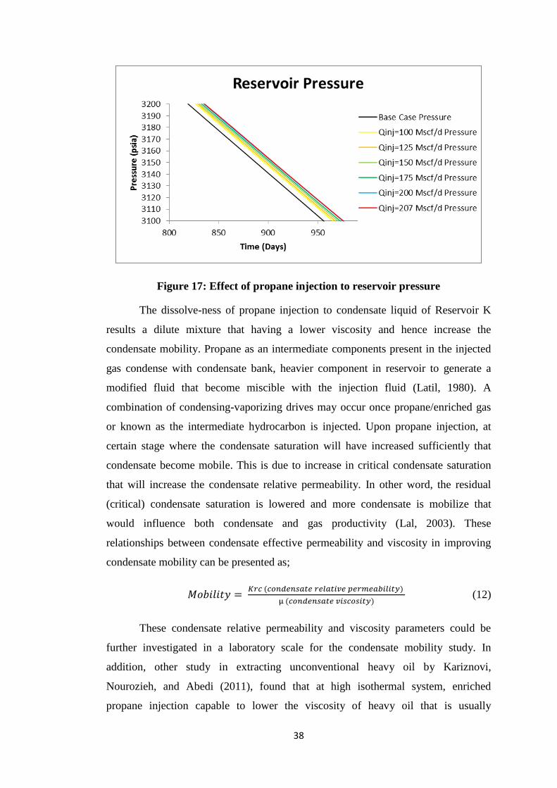
4.2 Effect of Propane Injection to Inflow Performance Relationship (IPR)
The results from E300 were then been used for IPM PROSPER IPR
modelling to investigate the effect of changes in reservoir pressure and skin
reduction contribution to IPR curve.
Figure 18: IPR Curve for March 2012 Model

40
Based on the IPR curve in Figure 18, there is an approximate 10 MMscf/day
additional to Absolute Open Flow (AOF) after propane injection from 87 MMscf/day
to 97 MMscf/day. This shows a significant improvement toward IPR curve of
Reservoir K under propane injection. This study assumes that condensate saturation
is minimized upon propane injection and hence lowering skin value as close as initial
skin value which is at a factor of 2. Jones gas IPR model was used in IPM PROSPER
software since the main inputs needed are reservoir pressure and skin. Jones, Blount,
and Glaze (1976) derived the flow equation from the field data correlation to
calculate the gas rate at constant flowing pressure that also considering the skin
effect and turbulent flow (non-Darcy flow effect). The equation can be expressed as;
( )
Where;
Pr = Reservoir static pressure, Pwf = Sandface flowing pressure, qg = Gas flow rate at
standard condition, a = turbulent flow term, and b = Darcy flow term
If the a and b coefficient have been determined from multi-rate test result,
deliverability can be estimated through;
√ (
)
( )
Once the coefficients of the deliverability equation have been determined, these
relationships can be used to estimate production rates for various bottom hole
flowing pressures. This could measure the ability of the reservoir to produce gas
from the wellbore by determining the rate versus pressure relationship.
However, for gas flow with condensate banking problem, which the gas flow
is restricted, the deliverability and a and b coefficient might be affected from the
Jones‘s correlated equation. Theoretically, skin or formation damage caused by
condensate banking problem may reduce in permeability at the altered zone causes
by an additional pressure drop, ∆Ps. The dimensionless skin factor, s, and the
additional pressure drop across the altered zone are related by;

41
(15)
Where;
∆Ps = Pressure drop due to skin, q = production rate, β = formation volume factor, µ
= viscosity, k = permeability, h = reservoir thickness, and s = dimensionless skin
factor
The skin factor affects the pressure drop and hence limits reservoir
performance. Therefore, propane injection could assist in mitigating condensate
banking problem by minimizing the condensate saturation near well bore and reduce
the skin factor.
Based on the Jones correlated equation, the IPR produced only represent the
reservoir performance at a particular time. Thus, to investigate reservoir performance
change in time, diffusivity equation (unsteady state fluid flow) is needed to be
applied. Based on the literature review, diffusivity equation formed from
combination of main equation of continuity equation and Darcy‘s fluid flow
equation. IPM MBAL software applies this diffusivity equation in order to forecast
reservoir performance. From the updated IPR Curve, Reservoir K performance under
propane injection could be investigated as shown in Figure 19.
Figure 19: IPM MBAL results on average gas rate and cumulative gas
production

42
Figure 19 shows Reservoir K performance after the updated IPR curve was
imported to IPM MBAL model. The average gas rate is being simulated (blue line)
from scheduled production constraint in IPM MBAL and predicted (red line) starts
from 31/3/2012 to 31/12/2013. It could be observed increase in well deliverability
and hence improve the gas recovery. Gas recovery improvement could be observed
from additional to cumulative gas production after the propane injection. The model
has been matched and this could be observed that historical (green line) and
simulated (pink line) cumulative gas production are matched. The model is then been
used to predict additional gas recovered (light blue) after propane injection.
It can be conclude that reduction in skin improves well deliverability that
increase the average gas rate and more hydrocarbon gas can be recovered. As
condensate is the by-product of produced gas, logically the condensate recovery also
can be improved.
4.3 Effect of Propane Injection to Reservoir K Recovery
After Reservoir K, IPM MBAL model has been matched and equipped by
improved IPR curve, hydrocarbon recovery prediction was conducted.
Figure 20: Cumulative Gas Production

43
There is an additional in gas cumulative production from the base case
cumulative production after propane injection as shown in Figure 20. At 7/3/2013,
backpressure was proposed to reduce from 900 psia to 700 psia that increase more
the cumulative gas production. It is predicted gas reserve to recover up to 17.7 Bscf
that brings 77% of recovery factor (increase 4% from the base case). On the other
hand, the cumulative condensate production could be observed in Figure 21;
Figure 21: Cumulative Condensate Production
The cumulative condensate production shown in Figure 21 predicts Reservoir
K to recover 288 MSTB of condensates that brings additional 6% of recovery factor
from the base case. The condensate recovery could be proved by GOR result from
E300;

44
Figure 22: Gas Oil Ratio (GOR) changes upon propane injection
Based on the Figure 22, it is observed that propane injection reduce the GOR
(approximate 36%) under 207 Mscf/d of propane injection. This shows that more
condensate able to recover as the lower the GOR, the higher the CGR (condensate
gas ratio). Therefore, propane injection not only recover more gas, but also capable
to recover more condensate liquid at the surface. These results are then been
collected to study on economic viability of this project to Reservoir K.
4.4 Quick Economic Evaluation
In economic perspective, production under propane injection could be
predicted brings additional 4.2 Million USD of revenue based on the quick economic
profile in Figure 23;
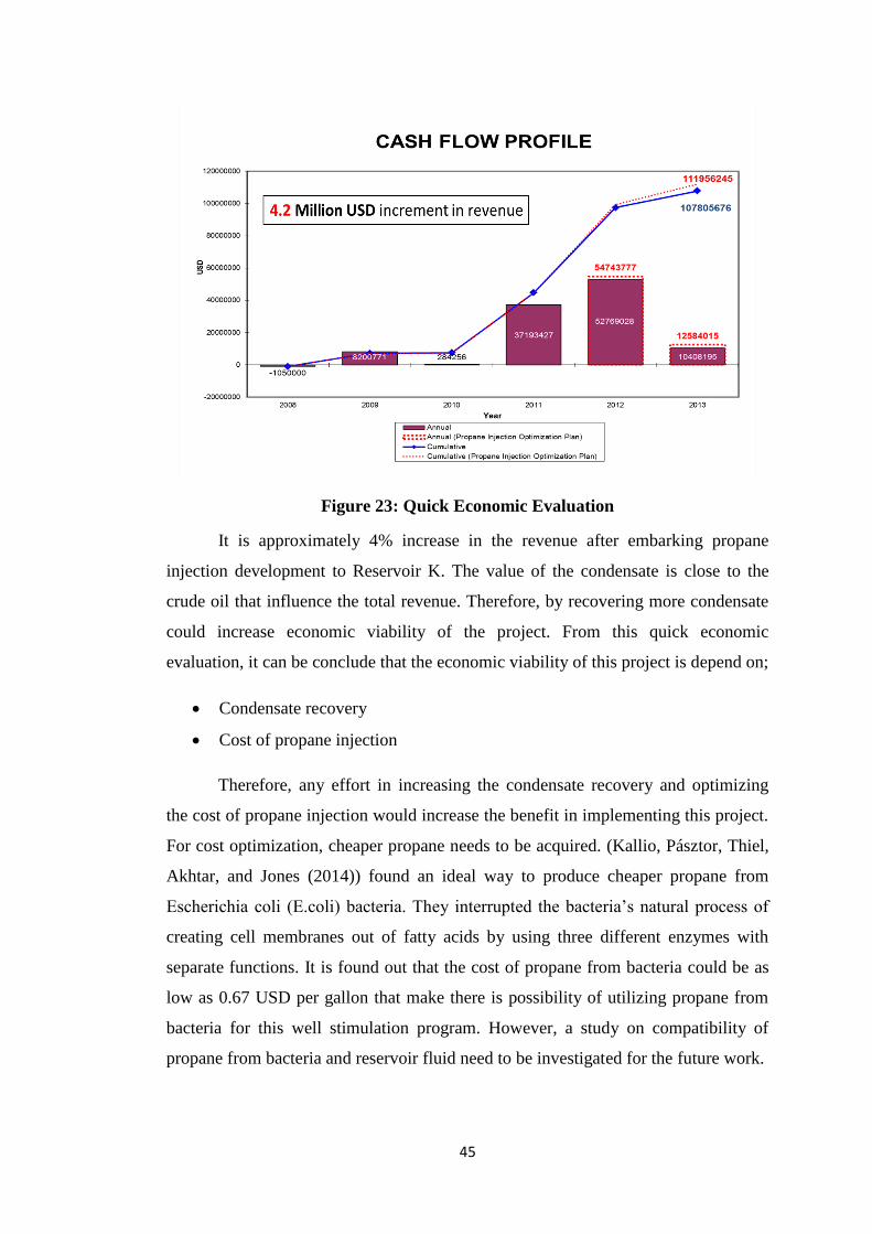
45
Figure 23: Quick Economic Evaluation
It is approximately 4% increase in the revenue after embarking propane
injection development to Reservoir K. The value of the condensate is close to the
crude oil that influence the total revenue. Therefore, by recovering more condensate
could increase economic viability of the project. From this quick economic
evaluation, it can be conclude that the economic viability of this project is depend on;
Condensate recovery
Cost of propane injection
Therefore, any effort in increasing the condensate recovery and optimizing
the cost of propane injection would increase the benefit in implementing this project.
For cost optimization, cheaper propane needs to be acquired. (Kallio, Pásztor, Thiel,
Akhtar, and Jones (2014)) found an ideal way to produce cheaper propane from
Escherichia coli (E.coli) bacteria. They interrupted the bacteria‘s natural process of
creating cell membranes out of fatty acids by using three different enzymes with
separate functions. It is found out that the cost of propane from bacteria could be as
low as 0.67 USD per gallon that make there is possibility of utilizing propane from
bacteria for this well stimulation program. However, a study on compatibility of
propane from bacteria and reservoir fluid need to be investigated for the future work.
46
As summary to the result and discussion part, it is found that propane
injection project could be part of the retrograde gas reservoir development. Study
shows that condensate banking problem can be removed by mobilizing the
condensate saturation at the bottom hole. Propane capable to clear the restriction of
gas to flow into the wellbore that increase well productivity and hence increases gas
recovery. The condensate liquid can recovered from mobilized high saturation of
condensate and produced along the gas flow. This could be observed from the
improved CGR that is close to the initial CGR. In economic view, condensate
recovery gives more contribution toward the project revenue compared to gas
recovery. On the other note, plan of optimizing the project cost also should be
considered. Thus, effort on both increases in condensate recovery and cost
optimization would contribute to a high profit of this project.
47
CHAPTER 5
CONCLUSION & RECOMMENDATION
5.1 Conclusion
As conclusion, the study is mainly to investigate the potential propane
injection to retrograde gas recovery compared to the normal industry practice under
natural depletion. There are additional 4% of gas recovery factor and 6% increase in
condensate recovery factor that brings 4.2 Million USD of revenue. In addition,
study shows that propane injection improve both gas and condensate performance as
propane capable to;
Reduce the dew point pressure that delay condensate bank formation
Dilute the condensate liquid at bottom hole that reduce condensate viscosity,
hence mobilize the condensate liquid
Theoretically maintain single phase fluid flow into the wellbore, increase gas
relative permeability, ease gas to flow, thus increase gas inflow performance
This study also found that reservoir IPR and hydrocarbon recovery could be
improved after the skin effect had been minimized. On the other hand, condensate
recovery and cost of propane is the main factors that determine the economic
viability of the project. Therefore, these factors could be improved and further
studied as part of gas development strategy.
5.2 Recommendation
Project study was basically focus on the effect of propane injection to
dissolve condensate saturation at bottom hole, influence of skin to reservoir IPR, and
how it contribute to reservoir recovery. However, there are still a lot of areas that

48
need to be covered as it is depending on what variables to study on for example
saturation changes in time or location. In this area of study which relates skin from
condensate bank, gas IPR, and hydrocarbon recovery, it is recommended to further
study on;
Micro-scale laboratory data such as relative permeability from Special Core
Analysis (SCAL), Constant Volume Depletion (CVD) test data and Constant
Composition Expansion (CCE) test data that could increase the quality of the
study
Reservoir actual geology model considering geology physical such as
dipping, folded, and channelling
Miscibility test to observe the minimum miscibility pressure (MMP) of
propane for reservoir fluid in N field
Cost optimization by using cheaper propane artificial produced from bacteria
and surface facilities study
As summary, the area of retrograde gas reservoir study could be presented as
shown in Figure 24;
Figure 24: Retrograde Gas Reservoir study area in hydrocarbon recovery
project

49
CHAPTER 6
REFERENCES
Abou-Kassem, J. H., Farouq-Ali, S., & Islam, M. R. (2013). Petroleum Reservoir
Simulations: Elsevier.
Ahmed, T., Evans, J., Kwan, R., & Vivian, T. (1998). Wellbore liquid blockage in
gas-condensate reservoirs. Paper presented at the SPE Eastern regional
meeting.
Al-Abri, A., & Amin, R. (2010). Phase behaviour, fluid properties and recovery
efficiency of immiscible and miscible condensate displacements by SCCO2
injection: experimental investigation. Transport in porous media, 85(3), 743-
756.
Al-Abri, A. S. (2011). Enhanced gas condensate recovery by CO2 injection: Curtin
University of Technology.
Al-Anazi, H. A., Al-Otaibi, M. A., Al-Faifi, M., & Hilab, V. V. Enhancement of Gas
Productivity Using Alcoholic Acids: Laboratory and Field Studies.
Al-Shawaf, A. M., Kelkar, M., & Sharifi, M. (2013). A New Method to Predict
Performance of Gas Condensate Reservoirs. SAUDI ARAMCO JOURNAL
OF TECHNOLOGY, 23.
Ayala, L. F., Ertekin, T., & Adewumi, M. A. (2006). Compositional modeling of
retrograde gas-condensate reservoirs in multimechanistic flow domains. SPE
Journal, 11(04), 480-487.
Bang, V. S. S., Pope, G. A., & Sharma, M. M. (2006). Phase Behavior Study of
Hydrocarbon/Water/Methanol Mixtures at Reservoir Conditions. Paper
presented at the SPE Annual Technical Conference and Exhibition.
Du, L., Walker, J. G., Pope, G. A., Sharma, M. M., & Wang, P. (2000). Use of
solvents to improve the productivity of gas condensate wells. paper SPE,
62935, 1-4.
Dumkwu, F. A. (2013). Integrated Reservoir Characterization and Modeling for
Enhanced Hydrocarbons Recovery from Mature Gas-condensate Reservoirs:
50
A Case Study of Big Escambia Creek Field, Escambia County, Alabama,
USA: University of Alabama Libraries.
Fan, L., Harris, B. W., Jamaluddin, A. J., Kamath, J., Mott, R., Pope, G. A., . . .
Whitson, C. H. (1998). Understanding gas-condensate reservoirs. Oilfield
Review, 10(3), 16-25.
Ferguson, M., Mamora, D., & Goite, J. (2001). Steam-propane injection for
production enhancement of heavy Morichal oil. Paper presented at the SPE
International Thermal Operations and Heavy Oil Symposium.
Gachuz-Muro, H., Gonzalez Valtierra, B. E., Luna, E. E., & Aguilar Lopez, B.
(2011). Laboratory Tests with CO2 N2 and Lean Natural Gas in a Naturally
Fractured Gas-Condensate Reservoir under HP/HT Conditions. Paper
presented at the SPE Enhanced Oil Recovery Conference.
Ghedan, S. (2009). Global laboratory experience of CO2-EOR flooding. Paper
presented at the SPE/EAGE Reservoir Characterization & Simulation
Conference.
Grigg, R., & Lingane, P. (1983). Predicting phase behavior of mixtures of reservoir
fluids with carbon dioxide. Paper presented at the SPE Annual Technical
Conference and Exhibition.
Gringarten, A., Al-Lamki, A., Daungkaew, S., Mott, R., & Whittle, T. (2000). Well
test analysis in gas-condensate reservoirs. Paper presented at the SPE annual
technical conference.
Hashemi, A., Nicolas, L., & Gringarten, A. C. (2006). Well test analysis of
horizontal wells in gas-condensate reservoirs. SPE Reservoir Evaluation &
Engineering, 9(01), 86-99.
Havlena, Z., Griffith, J., Pot, R., & Kiel, O. (1967). Condensate Recovery by Cycling
at Declining Pressure. Paper presented at the 7th World Petroleum Congress.
Hinchman, S., & Barree, R. (1985). Productivity loss in gas condensate reservoirs.
Paper presented at the SPE Annual Technical Conference and Exhibition.
Jamaluddin, A., Thomas, S., D‘Cruz, D., Nighswander, J., & Oilphase, S. (2001).
Experimental and theoretical assessment of using propane to remediate liquid
buildup in condensate reservoirs. paper SPE, 71526.
Jessen, K., & Orr, F. (2004). Gas cycling and the development of miscibility in
condensate reservoirs. SPE Reservoir Evaluation & Engineering, 7(05), 334-
341.

51
Jones, L. G., Blount, E., & Glaze, O. (1976). Use of short-term, multiple-rate flow
tests to predict performance of wells having turbulence: Mobil Research and
Development Corp.
Kallio, P., Pásztor, A., Thiel, K., Akhtar, M. K., & Jones, P. R. (2014). An
engineered pathway for the biosynthesis of renewable propane. Nature
communications, 5.
Kamath, J. Deliverability of Gas-Condensate Reservoirs — Field Experiences and
Prediction Techniques. doi: 10.2118/103433-JPT
Kariznovi, M., Nourozieh, H., & Abedi, J. (2011). Experimental and Modeling Study
of Vapor-Liquid Equilibrium for Propane/Heavy Crude Systems at High
Temperature Conditions. Paper presented at the SPE annual technical
conference and exhibition.
Kolbikov, S. V. (2010). Gas-Condensate Recovery For The Low Permeable Sands
Gas Cycling Efficiency. Paper presented at the SPE Russian Oil and Gas
Conference and Exhibition.
Kurdi, M., Xiao, J., & Liu, J. (2012). Impact of CO2 Injection on Condensate
Banking in Gas Condensate Reservoirs. Paper presented at the SPE Saudi
Arabia section Young Professionals Technical Symposium.
Lal, R. R. (2003). Well Testing in Gas-Condensate Reservoirs. STANFORD
UNIVERSITY.
Latil, M. (1980). Enhanced oil recovery: Editions OPHRYS.
Mamora, D., & Seo, J. (2002). Enhanced gas recovery by carbon dioxide
sequestration in depleted gas reservoirs. Paper presented at the SPE Annual
Technical Conference and Exhibition.
McCain, W. D. (1990). The properties of petroleum fluids: PennWell Books.
Monger, T., & Khakoo, A. (1981). The phase behavior of CO2-Appalachian oil
systems. Paper presented at the SPE Annual Technical Conference and
Exhibition.
Moradi, B., Tangsiri Fard, J., Rasaei, M. R., Momeni, A., & Bagheri, M. B. (2010).
Effect of Gas Recycling on the Enhancement of Condensate Recovery in an
Iranian Fractured Gas/Condensate Reservoir. Paper presented at the
Trinidad and Tobago Energy Resources Conference.
Moses, P. L., & Donohoe, C. W. Gas-Condensate Reservoirs (1987 PEH Chapter
39): Society of Petroleum Engineers.
52
Odi, U. Analysis and Potential of CO2 Huff-n-Puff for Near Wellbore Condensate
Removal and Enhanced Gas Recovery.
ODI, U. O. (2013). Optimal Process Design for Coupled CO2 Sequestration and
Enhanced Gas Recovery in Carbonate Reservoirs. Texas A&M University.
Olaberinjo, A., & Oyewola, O. (2006). Modelling the Effect of Compositional
Changes in Transient Flow of Gas Condensate Reservoirs. International
Journal of Fluid Mechanics Research, 33(6).
Oldenburg, C. M., & Benson, S. M. CO2 Injection for Enhanced Gas Production
and Carbon Sequestration.
Sayed, M. A., & Al-Muntasheri, G. A. Liquid Bank Removal in Production Wells
Drilled in Gas-condensate Reservoirs: A Critical Review.
Seto, C. J., Jessen, K., & Orr, F. M. (2007). Using analytical solutions in
compositional streamline simulation of a field-scale CO2-injection project in
a condensate reservoir. SPE Reservoir Evaluation & Engineering, 10(04),
393-405.
Sognesand, S. (1991). Long-term testing of vertically fractured gas condensate wells.
Paper presented at the SPE Production Operations Symposium.
Soroush, M., Hoier, L., & Kleppe, J. (2012). CO2 Injection and CO2 WAG in
Dipping Gas Condensate and Oil Reservoirs. Paper presented at the SPE
Improved Oil Recovery Symposium.
Taheri, A., Hoier, L., & Torsaeter, O. Miscible and Immiscible Gas Injection for
Enhancing of Condensate Recovery in Fractured Gas Condensate Reservoirs.
Thomas, F., Andersen, G., & Bennion, D. (2009). Gas condensate reservoir
performance. Journal of Canadian Petroleum Technology, 48(7), 18-24.
Thornton, O. (1946). Gas-Condensate Reservoirs-A Review. Drilling and
Production Practice.
Yarranton, H., Badamchi-Zadeh, A., Satyro, M., & Maini, B. (2008). Phase
Behaviour and Physical Properties of Athabasca Bitumen, Propane and CO.
Paper presented at the Canadian International Petroleum Conference.
Zaitsev, I., Dmitrievsky, S., Norvik, H., Yufin, P., Bolotnik, D., Sarkisov, G., &
Schepkina, N. (1996). Compositional modeling and PVT analysis of pressure
maintenance effect in gas condensate field: Comparative study. Paper
presented at the EUROPEC: European petroleum conference.


![Untitled-1 [] · pesantren islam al-irsyad ... universitas islam madinah saudi arabia accredited jenjang pendidikan : (putra / putri) sd islam tahfidzul qur'an ( mi/sd )](https://static.fdocuments.us/doc/165x107/5c79a0e309d3f200208ca171/untitled-1-pesantren-islam-al-irsyad-universitas-islam-madinah-saudi.jpg)