IMPROVED GPS SINGLE POINT POSITIONING USING …eprints.utem.edu.my/18638/1/Improved GPS Single...
24
IMPROVED GPS SINGLE POINT POSITIONING USING WEIGHTED LEAST SQUARE METHOD LOH KAH HOW This Report Is Submitted in Partial Fulfilment of Requirements for The Bachelor Degree of Electronic Engineering (Telecommunication Electronics) Faculty of Electronics and Computer Engineering Universiti Teknikal Malaysia Melaka June 2016
Transcript of IMPROVED GPS SINGLE POINT POSITIONING USING …eprints.utem.edu.my/18638/1/Improved GPS Single...
IMPROVED GPS SINGLE POINT POSITIONING USING WEIGHTED LEAST SQUARE METHOD
LOH KAH HOW
This Report Is Submitted in Partial Fulfilment of Requirements for The Bachelor
Degree of Electronic Engineering (Telecommunication Electronics)
Faculty of Electronics and Computer Engineering
Universiti Teknikal Malaysia Melaka
June 2016
i
UNIVERSTI TEKNIKAL MALAYSIA MELAKA
FAKULTI KEJURUTERAAN ELEKTRONIK DAN KEJURUTERAAN KOMPUTER
BORANG PENGESAHAN STATUS LAPORAN
PROJEK SARJANA MUDA II
Tajuk Projek : Improved GPS Single Point Positioning using Weighted Least
Square Method
Sesi Pengajian : 1 5 / 1 6
Saya LOH KAH HOW
mengaku membenarkan Laporan Projek Sarjana Muda ini disimpan di Perpustakaan dengan syarat-syarat kegunaan seperti berikut:
1. Laporan adalah hakmilik Universiti Teknikal Malaysia Melaka.
2. Perpustakaan dibenarkan membuat salinan untuk tujuan pengajian sahaja.
3. Perpustakaan dibenarkan membuat salinan laporan ini sebagai bahan pertukaran antara institusi
pengajian tinggi.
4. Sila tandakan ( √ ) :
SULIT* *(Mengandungi maklumat yang berdarjah keselamatan atau kepentingan Malaysia seperti yang termaktub di dalam AKTA RAHSIA RASMI 1972)
TERHAD** **(Mengandungi maklumat terhad yang telah ditentukan oleh organisasi/badan di mana penyelidikan dijalankan)
TIDAK TERHAD
Disahkan oleh:
__ ________________________ ___________________________________
(TANDATANGAN PENULIS) (COP DAN TANDATANGAN PENYELIA)
Tarikh: ……………………….. Tarikh: ………………………..

ii
STUDENT’S DECLARATION
“I hereby declare that the work in this project is my own except for summaries and quotations which have been duly acknowledge.”
Signature : .......................................................
Author : .......................................................
Date : .......................................................

iii
SUPERVISOR’S DECLARATION
“I acknowledge that I have read this report and in my opinion this report is sufficient in term of scope and quality for the award of Bachelor of Electronic Engineering
Electronic Telecommunication with Honour’s.”
Signature : .......................................................
Supervisor’s Name : .......................................................
Date : .......................................................

iv
ACKNOWLEDGEMENT
This final year project report could be realized with the sincere help and support
from many people. I am very appreciating their help and support.
Firstly, I would like to thank my final year project supervisor, Dr Ho Yih Hwa
for his complete support in geodetic knowledge and the excellent guidance in my final
year project. I was impressed with his knowledge in geodetic sciences. I really enjoy
studying of GPS single point positioning. The position of a receiver can be calculated
by using the least square method which is a numerical calculation to estimate the
approximation position of receiver. Besides, Dr Ho is friendly behavior while
answering my question and always give the comment and suggestion for me. So that,
the project having the improvement with his continuous supervision.
Next, I would like to thank the final year project panels. They are the persons
who give the questions, comments and suggestions on my project and presentation
works. The comments for my presentation is valuable for the future. It should be
improving for the future.
Finally, I would like to thank to my parents and friends who give the motivation
and encouragement to me. I am very appreciating to all of the person who give
guidance and motivation support for me to complete this final year project.
v
ABSTRACT
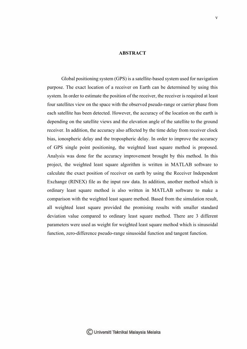
Global positioning system (GPS) is a satellite-based system used for navigation
purpose. The exact location of a receiver on Earth can be determined by using this
system. In order to estimate the position of the receiver, the receiver is required at least
four satellites view on the space with the observed pseudo-range or carrier phase from
each satellite has been detected. However, the accuracy of the location on the earth is
depending on the satellite views and the elevation angle of the satellite to the ground
receiver. In addition, the accuracy also affected by the time delay from receiver clock
bias, ionospheric delay and the tropospheric delay. In order to improve the accuracy
of GPS single point positioning, the weighted least square method is proposed.
Analysis was done for the accuracy improvement brought by this method. In this
project, the weighted least square algorithm is written in MATLAB software to
calculate the exact position of receiver on earth by using the Receiver Independent
Exchange (RINEX) file as the input raw data. In addition, another method which is
ordinary least square method is also written in MATLAB software to make a
comparison with the weighted least square method. Based from the simulation result,
all weighted least square provided the promising results with smaller standard
deviation value compared to ordinary least square method. There are 3 different
parameters were used as weight for weighted least square method which is sinusoidal
function, zero-difference pseudo-range sinusoidal function and tangent function.
vi
ABSTRAK
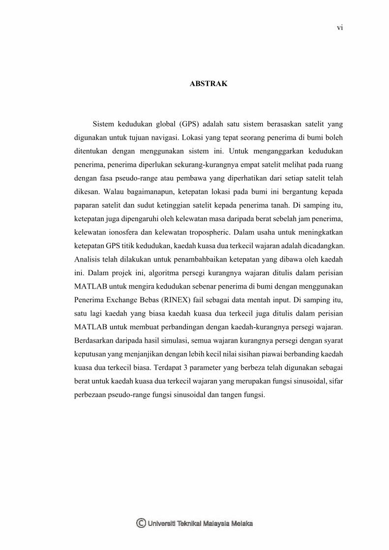
Sistem kedudukan global (GPS) adalah satu sistem berasaskan satelit yang
digunakan untuk tujuan navigasi. Lokasi yang tepat seorang penerima di bumi boleh
ditentukan dengan menggunakan sistem ini. Untuk menganggarkan kedudukan
penerima, penerima diperlukan sekurang-kurangnya empat satelit melihat pada ruang
dengan fasa pseudo-range atau pembawa yang diperhatikan dari setiap satelit telah
dikesan. Walau bagaimanapun, ketepatan lokasi pada bumi ini bergantung kepada
paparan satelit dan sudut ketinggian satelit kepada penerima tanah. Di samping itu,
ketepatan juga dipengaruhi oleh kelewatan masa daripada berat sebelah jam penerima,
kelewatan ionosfera dan kelewatan tropospheric. Dalam usaha untuk meningkatkan
ketepatan GPS titik kedudukan, kaedah kuasa dua terkecil wajaran adalah dicadangkan.
Analisis telah dilakukan untuk penambahbaikan ketepatan yang dibawa oleh kaedah
ini. Dalam projek ini, algoritma persegi kurangnya wajaran ditulis dalam perisian
MATLAB untuk mengira kedudukan sebenar penerima di bumi dengan menggunakan
Penerima Exchange Bebas (RINEX) fail sebagai data mentah input. Di samping itu,
satu lagi kaedah yang biasa kaedah kuasa dua terkecil juga ditulis dalam perisian
MATLAB untuk membuat perbandingan dengan kaedah-kurangnya persegi wajaran.
Berdasarkan daripada hasil simulasi, semua wajaran kurangnya persegi dengan syarat
keputusan yang menjanjikan dengan lebih kecil nilai sisihan piawai berbanding kaedah
kuasa dua terkecil biasa. Terdapat 3 parameter yang berbeza telah digunakan sebagai
berat untuk kaedah kuasa dua terkecil wajaran yang merupakan fungsi sinusoidal, sifar
perbezaan pseudo-range fungsi sinusoidal dan tangen fungsi.

vii
TABLE OF CONTENTS
CHAPTER TITLES PAGES
STUDENT’S DECLARATION ii
SUPERVISOR’S DECLARATION iii
ACKNOWLEDGEMENT iv
ABSTRACT v
ABSTRAK vi
TABLE OF CONTENTS vii
LIST OF FIGURES x
LIST OF TABLES xi
LIST OF ABBREVIATIONS xii
I INTRODUCTION
1 OVERVIEW 1
1.1 PROJECT BACKGROUND 1
1.2 PROBLEM STATEMENT 2
1.3 OBJECTIVES 3
1.4 SCORE OF PROJECT 3
1.5 REPORT OUTLINE 3
II LITERATURE REVIEW
2 OVERVIEW 5
2.1 INTRODUCTION TO GNSS 5
2.1.1 Important of GNSS 5
2.2 GLOBAL POSITIONING SYSTEM 6
viii
2.2.1 Space segment 6
2.2.2 Control segment 7
2.2.3 User segment 7
2.3 BASIC GPS POSITIONING 9
2.4 GPS SIGNALING 10
2.5 SOURCES OF ERROR 11
2.5.1 Denial of accuracy 11
2.5.2 Ionospheric delay 12
2.5.3 Tropospheric delay 12
2.5.4 Satellite clock offset 13
2.6 GPS DATA 13
2.6.1 RINEX Files 13
2.6.2 SP3 files 16
2.7 LEAST SQUARE METHODS 16
III METHODOLOGY
3 OVERVIEW 19
3.1 PROJECT FLOW CHART 19
3.2 COLLECT AND CALCULATE DATA 21
3.2.1 Import RINEX raw data 21
3.2.2 Satellites coordination calculation 22
3.2.3 Error sources correction 26
3.2.4 Least square method 30
3.3 DATA ANALYSIS 31
3.3.1 Mean 31
3.3.2 Standard deviation 31
3.3.3 Variation of each sample relative to first epoch 32
3.3.4 Satellites’ orbit view 32
IV RESULTS AND DISCUSSION

ix
4 OVERVIEW 33
4.1 RESULTS 33
4.2 DISCUSSION 39
V CONCLUSION AND RECOMMENDATIONS
5 OVERVIEW 44
5.1 CONCLUSION 44
5.2 FUTURE WORKS 44
VI REFERENCES 46
x
LIST OF FIGURES
FIGURE TITLES PAGES 2.1 Basic GPS satellite constellation 6
2.2 GPS control segment 7
2.3 3D Positioning 8
2.4 Trilateration Positioning 8
2.5 Example of navigation file 15
2.6 Example of observation file 15
2.7 Example of sp3 file 16
2.8 RMS error (m) of positioning for eight methods 18
3.1 Project flowchart 20
3.2 Example of O-file format 22
4.1 Algorithm in MATLAB software 33
4.2 GUI to import N-file 34
4.3 GUI to import O-file 34
4.4 Navigation data from N-file 35
4.5 Coordinate of satellite 35
4.6 3D view of satellites coordinate 36
4.7 Delta X of user position 36
4.8 Position over time 37
4.9 Observation data from O-file 38
4.10 Scatter plot of latitude and longitude 38
4.11 Scatter plot of ECEF 39

xi
LIST OF TABLES
TABLE TITLES PAGES 3-1 Data format of N-file. 22
4-1 Standard Deviation of each least square method 40
4-2 Mean of user position from each least square method 41
4-3 Variation of approximate position with mean position 41
4-4 DOP for each least square method 42
4-5 Value of DOP 43

xii
LIST OF ABBREVIATIONS
CA - Coarse Acquisition or Clear Acquisition DOP - Dilution of Precision DRMS - Distance Root Mean Square ECEF - Earth Center Earth Fixed GDOP - Geometrical Dilution of Precision GNSS - Global Navigation Satellite System GPS - Global Positioning System HDOP - Horizontal Dilution of Precision LLA - Latitude Longitude Altitude MATLAB - Matrix Laboratory MEO - Medium Earth Orbit OLS - Ordinary Least Square PDOP - Position Dilution of Precision RINEX - Receiver Independent Exchange SA - Selective Availability TDOP - Time Dilution of Precision VDOP - Vertical Dilution of Precision WGS84 - World Geodetic System 1984 WLS - Weighted Least Square
1
CHAPTER 1
INTRODUCTION
1 OVERVIEW
This chapter is discussed the introduction to the project. The project
background is briefly introduced the GPS and the important of the GPS system. Next,
the project problem statement is stated clearly and proposed the solution. In order to
achieve the objectives, the scope of project is fixed and carried the methodology the
to achieve the objective of project.
1.1 Project background
In this era, Global Positioning System (GPS) plays the important role among the
civilians and the military applications. For civilians, it is always useful in the
navigation system. The users can go everywhere by using a low cost GPS receiver in
car even through a smartphone for route navigation purpose.
However, the accuracy of navigation is not that critical compared to the rescue
and life-saving application. Nowadays the most important role for GPS development
is the emergency solution which is the critical application for rescue and life-saving
[1]. In addition, the GPS applications also including the agriculture control, aerospace
and marine navigation.
Moreover, the military also use the GPS to control the nuclear weapons and the
GPS surveillance system. Those critical applications need a very high accuracy and
sophisticated GPS receiver used in the system. For emergency solution in rescue and

2
life-saving, the position provided by a 2G and 3G mobile network in very low accuracy.
Hence, it has possibility located to a position which is inaccurate from the actual
position. In this situation, the position provided by a GPS is better than the mobile
network. However, the accuracy of GPS also depends on the quality of GPS receiver,
the signal loss and time delay in the free space propagation. A best approximation
algorithm is needed for a low cost GPS receiver in order to calculate better accurate
position for critical application.
In this project, weighted least square method is proposed to improve accuracy of
a low cost GPS receiver for single point positioning. This weighted least square
method is compared to the ordinary least square method in order to know the
improvement brought by weighted least square method.
.
1.2 Problem statement
Nowadays, Global Positioning System (GPS) is play an important role in space–
based navigation system. The GPS single point positioning is often used in the critical
application such as rescue and life-saving. The accuracy of the coordinate of the user
or receiver is very important for the saving and rescue mission to positioning search
victim accurately and take the action plan immediately.
However, the accuracy for user’s receiver is affected by the satellite views in the
space. Since the Selectivity Availability is switch off on 1 May 2000, the error
correction is only including the satellite clock offset, ionospheric delay and
tropospheric delay [2][3][4]. The path of the GPS signal affects the accuracy of user
position due to the ionospheric delay and tropospheric delay. If the GPS satellite signal
from the longer path will affected more on the ionospheric delay and tropospheric
delay.
In order to improve the accuracy position of the user, weighted least square
method is proposed to overcome this problem by defining the weight compared the
3
shorter path to each satellite path. The algorithm is written in MATLAB software, and
using the least square method with the RINEX data from observation and navigation
file were post processing to estimate the position of user.
1.3 Objectives
The main objectives of this project is to analyze the improvement GPS single point
positioning by using weighted least square method. The GPS single point positioning
is using the L1 frequency (1575.42 MHz).
To develop the ordinary least square and weighted least square algorithm in
MATLAB for GPS positioning computation.
To analyze and study the improvement of accuracy brought by weighted least
square method.
1.4 Score of project
This project is focused on L1 frequency of GPS single point positioning to
determine the receiver coordinate in Earth Center Earth Fixed (ECEF) coordination.
The algorithm tested in this project is written in MATLAB software with the RINEX
v2.11 navigation and observation file as the input data to estimate the approximation
location of GPS receiver by using ordinary least square and weighted least square
method. The single point positioning model is based on world geodetic system 1984
(WGS84) datum and the errors correction are included for satellite offset clock error,
satellite relativistic clock error, ionospheric delay based on Klobuchar model and
tropospheric delay based on Hopfield model.
1.5 Report outline
This report is divided into 5 chapters. In chapter 1, the introduction of the project
is explained clearly with the problem statement, objectives of project, score of project
and the project methodology which is discussed the entire work flow of this project.
In chapter 2, the introduction to the GPS is discussed in theoretical and provide the
previous researchers’ works to compare the work flow and improvement from their
proposed models and method in order to determine the approximation receiver
4
coordination. In chapter 3, the methodology of this project is explained clearly with
the work flow of algorithm as written in MATLAB software. Next, chapter 4 is
demonstrated the output result of the algorithm and analyzed the results based on the
approximation position from the RINEX observation file, ordinary least square and
weighted least square method. The discussion on the analysis is included at the last
part of chapter 4. Followed by chapter 5, the conclusion of the project and the future
work for this project improvement.
5
CHAPTER 2
LITERATURE REVIEW
2 OVERVIEW
This chapter is briefly explained the GPS constellation and the basic concept
for single point positioning. Then, the degradation of GPS signal that caused by the
source of errors in signal propagation from space segment to ground segment is
discussed. Next, there will be a short introduction to the raw data of GPS which is the
RINEX file format. Lastly, least square methods are discussed in detail and comparing
the previous work of others researchers.
2.1 Introduction to GNSS
Global Navigation Satellite System (GNSS) is the infrastructure that allows
users with a compatible device to determine their position, velocity and local time by
processing signals from satellites in space. There are 4 common satellite constellation
under GNSS which is GPS developed by US, GLONASS developed by Russian,
Galileo developed by European Union and BEIDOU developed by China [1].
2.1.1 Important of GNSS
GNSS is used in many applications including the professional and the safety-critical
applications such as safety of life, search and rescue services. However, this is
depending on the need of users to declare the important of the GNSS performance.
The performance including availability, accuracy, continuity, integrity and indoor
penetration [1][5][6].
6
2.2 Global Positioning System
Global Positioning System (GPS) is the utility owned by US Department of
Defense. The main purpose of having this system is to provide the users with
positioning, navigating and timing services at all the time. Basically, GPS is divided
into 3 segment which is space segment, control segment and users segment to control
and monitor the satellite vehicles in the space. In addition, the orbits design of GPS is
different from other satellite constellation [5][6].
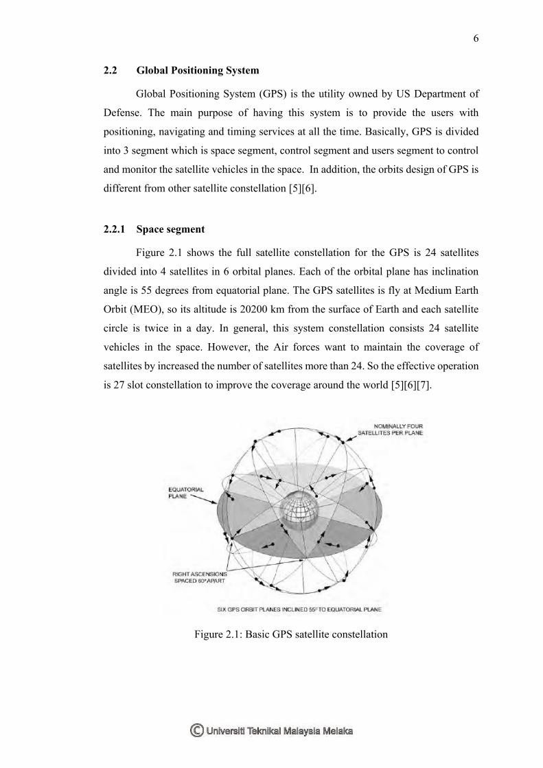
2.2.1 Space segment
Figure 2.1 shows the full satellite constellation for the GPS is 24 satellites
divided into 4 satellites in 6 orbital planes. Each of the orbital plane has inclination
angle is 55 degrees from equatorial plane. The GPS satellites is fly at Medium Earth
Orbit (MEO), so its altitude is 20200 km from the surface of Earth and each satellite
circle is twice in a day. In general, this system constellation consists 24 satellite
vehicles in the space. However, the Air forces want to maintain the coverage of
satellites by increased the number of satellites more than 24. So the effective operation
is 27 slot constellation to improve the coverage around the world [5][6][7].
Figure 2.1: Basic GPS satellite constellation

7
2.2.2 Control segment
Figure 2.2 shows the location of control segment. The control segment consists
of ground facilities in global network to track, control and monitor the location of the
satellite vehicles and its transmission, perform analyses and send commands and data
to the constellation. This segment is divided into several station such as a master
control station, an alternative master control station, twelve command and control
antennas and sixteen monitoring station. The master control station is set at Colorado
which is main system control directly to each satellite vehicle to set their navigation
message in order to have the accurate information of ephemeris data [5][6][7].
Figure 2.2: GPS control segment
2.2.3 User segment
User segment is the GPS compatible devices which is used to receive the GPS
signal and determine the position of the users. Beside, these devices also can be used
in navigation and timing calculation [8]. But, the accuracy of the GPS receiver is
depended on the type of receiver. A low cost receiver is using the standard positioning
service (SPS) so that the Coarse Acquisition (C/A) code is used to determine the
position of receiver. For the precise positioning service (PPS) is more accurate but it
8
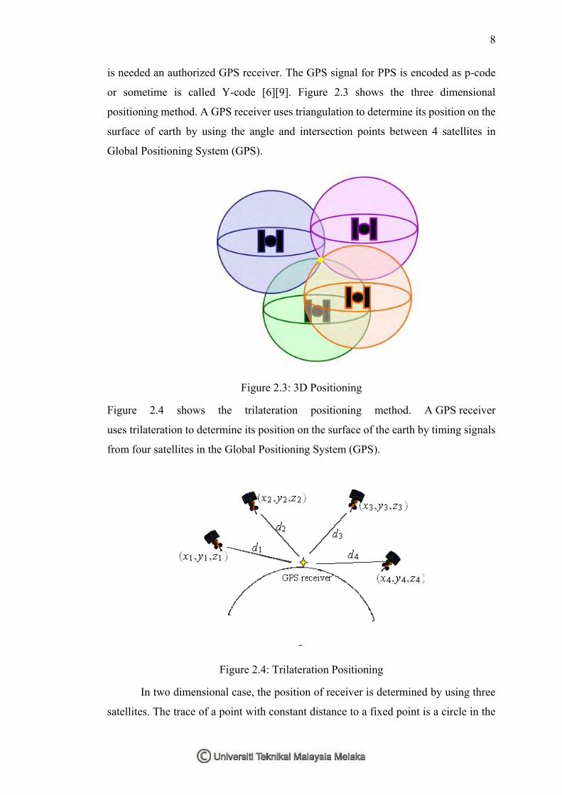
is needed an authorized GPS receiver. The GPS signal for PPS is encoded as p-code
or sometime is called Y-code [6][9]. Figure 2.3 shows the three dimensional
positioning method. A GPS receiver uses triangulation to determine its position on the
surface of earth by using the angle and intersection points between 4 satellites in
Global Positioning System (GPS).
Figure 2.3: 3D Positioning
Figure 2.4 shows the trilateration positioning method. A GPS receiver
uses trilateration to determine its position on the surface of the earth by timing signals
from four satellites in the Global Positioning System (GPS).
Figure 2.4: Trilateration Positioning
In two dimensional case, the position of receiver is determined by using three
satellites. The trace of a point with constant distance to a fixed point is a circle in the

9
two-dimensional case. Two satellites have two intersection point for the user’s position.
Hence, the third satellite is used to determine the exact user’s position. In three
dimensional case, the position of receiver is determined by using four satellites. Three
satellites are used to determine the latitude, longitude and altitude. The equal-distance
trace to a fixed point is a sphere in a three-dimensional case. Two spheres intersect to
make a circle. This circle intersects another sphere to produce two points. In order to
determine which point is the user position, one more satellite is needed[10].
2.3 Basic GPS positioning
The basic of GPS positioning to be establish is at least to have 4 satellites to
determine the position of a GPS receiver [8][11]. However, a 2D positioning is
required 3 satellites to determine the location in latitude and longitude. But 3D
positioning is required minimum 4 satellites to determine the location in latitude,
longitude and altitude. The basic positioning for 4 satellite is shown in equation (2-1)
to (2-4):
𝜌1 = √(𝑥 − 𝑥1)2 + (𝑦 − y1)
2 + (𝑧 − 𝑧1)2 + 𝜀1 (2-1)
𝜌2 = √(𝑥 − 𝑥2)2 + (𝑦 − y2)
2 + (𝑧 − 𝑧2)2 + 𝜀2 (2-2)
𝜌3 = √(𝑥 − 𝑥3)2 + (𝑦 − y3)
2 + (𝑧 − 𝑧3)2 + 𝜀3 (2-3)
𝜌4 = √(𝑥 − 𝑥4)2 + (𝑦 − y4)
2 + (𝑧 − 𝑧4)2 + 𝜀4 (2-4)
where 𝜌𝑖 is pseudo-range in meters, and x, y, and z is the ECEF coordinate of receiver
in meters, the 𝑥𝑖 , 𝑦𝑖 and 𝑧𝑖 are the ECEF coordinate of satellite. The 𝑖 indicates the
number of satellites. The 𝜀𝑖 is the clock bias error [9].
Equation (2-1) to (2-4) is the equation for 1 satellite pseudo range relative to
the earth station receiver. For a 3D positioning, there is at least 4 satellites, so that it
need 4 equations to determine the location of receiver. This equation is a non-linear
equation which is required the Taylor’s series method to linearize the equation in (2-
1) to (2-4) and solve the equation in least square method. The method proposed to
solve this equation is using the ordinary least square and weighted least square
methods to determine the value of x, y and z by assuming the initial value of Δx, Δy

10
and Δz are 0. If the x, y and z are the coordinate from the receiver, 𝑥𝑖, 𝑦𝑖 and 𝑧𝑖 is the
coordinate of the satellites view in the space and 𝜀 = 𝑐𝑡, c is the speed of light, 𝑡 is the
clock bias of user receiver. The value 𝑖 is the number of satellites view. Pseudo-range
is the sum of the actual range and the offset due to the user clock bias. In order to
calculate the coordinate of user, receiver is using a linear equation to solve the 4
unknown value. Hence, the value of x, y and z are
𝑥 = 𝑥𝑛 + Δ𝑥
𝑦 = 𝑦𝑛 + Δ𝑦
𝑧 = 𝑧𝑛 + Δ𝑧
𝑡 = 𝑡𝑛 + Δ𝑡
𝜌𝑖 = 𝜌𝑛𝑖 + Δ𝜌𝑖
The equation (2-1) to (2-4) is simplified as in equation (2-5)
[𝑋𝑛− 𝑋𝑖
𝜌𝑛𝑖−𝑐𝑡𝑛] (Δ𝑥) + [
𝑌𝑛− 𝑌𝑖
𝜌𝑛𝑖−𝑐𝑡𝑛] (Δ𝑦) + [
𝑍𝑛− 𝑍𝑖
𝜌𝑛𝑖−𝑐𝑡𝑛] (Δ𝑧) + 𝑐Δ𝑡 = Δ𝜌𝑖 (2-5)
This equation is represented one satellite. There are at least 4 satellites are
detected, the equation is formed with the 4 x 4 matrix. Then, the solution of Δ𝑥, Δ𝑦,
Δ𝑧 and Δ𝑡 are determined by using the least square method as in equation (2-6) and
(2-7).
2.4 GPS signaling
GPS signaling is the electromagnetic wave which is propagated from space to
earth station. This EM signal is generated by atomic clock in satellite vehicle which is
used to transmit PRN code to the receiver in L1 or L2 frequency. L1 is 1575.42 MHz
and L2 is 1227.6 MHz but the fundamental frequency for both L1 and L2 are
1023Mbit/s the navigation data the code from each satellite is modulated into GPS
signal and transmit signal to the ground receiver. There are two types of code is
transmitted which is C/A code and P-code[12].
Coarse Acquisition or Clear Acquisition (C/A) code is the standard GPS PRN
codes. It also known as the Civilian Code or S-Code. This code is only modulated with

11
the L1 carrier frequency and it is used to acquire and decode the L1 satellite signals so
that L1 pseudo-range measurements can be made (the Block IIR-M satellites add
another civil code on the L2 frequency). GPS receivers internally generate the PRN
string of bit code of for each GPS satellite and align the code to lock on to each signal.
The 1.023 MHz chip C/A code repeats every 1 milliseconds giving a code chip length
of 300 m which, is very easy to lock onto[13]. The Precise or Protected code with a
pseudorandom string of bits that is used by GPS receivers to determine the range to
the transmitting GPS satellite on the GPS L1 and L2 carrier at a chip rate of 10.23MHz
(approximately 10 times the resolution of the C/A code), which repeats about every
267 days. Each week segment of this code is unique to a GPS satellite and is reset each
week. Under the policy of the DoD, the P-code is replaced by an encrypted Y-code
when Anti-Spoofing is active. Y-code is intended to be available only to authorized
(primarily military) users.
2.5 Sources of error
This section will discuss the sources of error. The error is introduced by the
GPS signals that travel a long distance from space to earth. So, there will be consists
of error on delay and the required mitigate the effect to obtain the better accurate
position. Since the SA is removed, the atmosphere layer is the dominant issue that
affect the signal propagation path.
2.5.1 Denial of accuracy
Denial of accuracy is the selective availability (SA) which is introduced by US
government intentionally degrade the autonomous position capability of GPS for
civilian use. This intentionally degradation is done by artificially make the clock error
in the satellites and truncating the satellite ephemeris data. SA is activated on March
1990 and was turned off on May 2000 until now [2][3][4]. So that, the majority of
accuracy error of GPS navigation and positioning is caused by SA before May 2000.
Since the selective availability is removed, the majority error on accuracy nowadays
is introduced by atmosphere of earth which is ionosphere and troposphere effect.