Improved Electrical Conductivity of Polyvinyl Alcohol ... · MWCNTs may be interconnected, ......
7
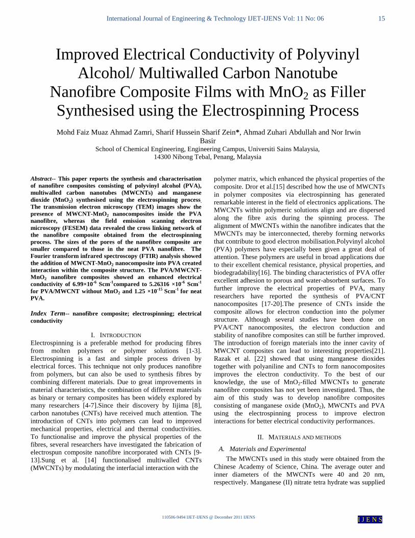
International Journal of Engineering & Technology IJET-IJENS Vol: 11 No: 06 15 110506-9494 IJET-IJENS @ December 2011 IJENS I J E N S Abstract-- This paper reports the synthesis and characterisation of nanofibre composites consisting of polyvinyl alcohol (PVA), multiwalled carbon nanotubes (MWCNTs) and manganese dioxide (MnO 2 ) synthesised using the electrospinning process . The transmission electron microscopy (TEM) images show the presence of MWCNT-MnO 2 nanocomposites inside the PVA nanofibre, whereas the field emission scanning electron microscopy (FESEM) data revealed the cross linking network of the nanofibre composite obtained from the electrospinning process. The sizes of the pores of the nanofibre composite are smaller compared to those in the neat PVA nanofibre. The Fourier transform infrared spectroscopy (FTIR) analysis showed the addition of MWCNT-MnO 2 nanocomposite into PVA created interaction within the composite structure. The PVA/MWCNT- MnO 2 nanofibre composites showed an enhanced electrical conductivity of 6.99×10 -6 Scm -1 compared to 5.26316 ×10 -6 Scm -1 for PVA/MWCNT without MnO 2 and 1.25 ×10 -15 Scm -1 for neat PVA. Index Term-- nanofibre composite; electrospinning; electrical conductivity I. INTRODUCTION Electrospinning is a preferable method for producing fibres from molten polymers or polymer solutions [1-3]. Electrospinning is a fast and simple process driven by electrical forces. This technique not only produces nanofibre from polymers, but can also be used to synthesis fibres by combining different materials. Due to great improvements in material characteristics, the combination of different materials as binary or ternary composites has been widely explored by many researchers [4-7].Since their discovery by Iijima [8], carbon nanotubes (CNTs) have received much attention. The introduction of CNTs into polymers can lead to improved mechanical properties, electrical and thermal conductivities. To functionalise and improve the physical properties of the fibres, several researchers have investigated the fabrication of electrospun composite nanofibre incorporated with CNTs [9- 13].Sung et al. [14] functionalised multiwalled CNTs (MWCNTs) by modulating the interfacial interaction with the polymer matrix, which enhanced the physical properties of the composite. Dror et al.[15] described how the use of MWCNTs in polymer composites via electrospinning has generated remarkable interest in the field of electronics applications. The MWCNTs within polymeric solutions align and are dispersed along the fibre axis during the spinning process. The alignment of MWCNTs within the nanofibre indicates that the MWCNTs may be interconnected, thereby forming networks that contribute to good electron mobilisation.Polyvinyl alcohol (PVA) polymers have especially been given a great deal of attention. These polymers are useful in broad applications due to their excellent chemical resistance, physical properties, and biodegradability[16]. The binding characteristics of PVA offer excellent adhesion to porous and water-absorbent surfaces. To further improve the electrical properties of PVA, many researchers have reported the synthesis of PVA/CNT nanocomposites [17-20].The presence of CNTs inside the composite allows for electron conduction into the polymer structure. Although several studies have been done on PVA/CNT nanocomposites, the electron conduction and stability of nanofibre composites can still be further improved. The introduction of foreign materials into the inner cavity of MWCNT composites can lead to interesting properties[21]. Razak et al. [22] showed that using manganese dioxides together with polyaniline and CNTs to form nanocomposites improves the electron conductivity. To the best of our knowledge, the use of MnO 2 -filled MWCNTs to generate nanofibre composites has not yet been investigated. Thus, the aim of this study was to develop nanofibre composites consisting of manganese oxide (MnO 2 ), MWCNTs and PVA using the electrospinning process to improve electron interactions for better electrical conductivity performances. II. MATERIALS AND METHODS A. Materials and Experimental The MWCNTs used in this study were obtained from the Chinese Academy of Science, China. The average outer and inner diameters of the MWCNTs were 40 and 20 nm, respectively. Manganese (II) nitrate tetra hydrate was supplied Improved Electrical Conductivity of Polyvinyl Alcohol/ Multiwalled Carbon Nanotube Nanofibre Composite Films with MnO 2 as Filler Synthesised using the Electrospinning Process Mohd Faiz Muaz Ahmad Zamri, Sharif Hussein Sharif Zein*, Ahmad Zuhari Abdullah and Nor Irwin Basir School of Chemical Engineering, Engineering Campus, Universiti Sains Malaysia, 14300 Nibong Tebal, Penang, Malaysia
Transcript of Improved Electrical Conductivity of Polyvinyl Alcohol ... · MWCNTs may be interconnected, ......
International Journal of Engineering & Technology IJET-IJENS Vol: 11 No: 06 15
110506-9494 IJET-IJENS @ December 2011 IJENS I J E N S
Abstract-- This paper reports the synthesis and characterisation
of nanofibre composites consisting of polyvinyl alcohol (PVA),
multiwalled carbon nanotubes (MWCNTs) and manganese
dioxide (MnO2) synthesised using the electrospinning process.
The transmission electron microscopy (TEM) images show the
presence of MWCNT-MnO2 nanocomposites inside the PVA
nanofibre, whereas the field emission scanning electron
microscopy (FESEM) data revealed the cross linking network of
the nanofibre composite obtained from the electrospinning
process. The sizes of the pores of the nanofibre composite are
smaller compared to those in the neat PVA nanofibre. The
Fourier transform infrared spectroscopy (FTIR) analysis showed
the addition of MWCNT-MnO2 nanocomposite into PVA created
interaction within the composite structure. The PVA/MWCNT-
MnO2 nanofibre composites showed an enhanced electrical
conductivity of 6.99×10⁻⁶ Scm-1compared to 5.26316 ×10⁻⁶ Scm-1
for PVA/MWCNT without MnO2 and 1.25 ×10⁻¹⁵ Scm-1 for neat
PVA.
Index Term-- nanofibre composite; electrospinning; electrical
conductivity
I. INTRODUCTION
Electrospinning is a preferable method for producing fibres
from molten polymers or polymer solutions [1-3].
Electrospinning is a fast and simple process driven by
electrical forces. This technique not only produces nanofibre
from polymers, but can also be used to synthesis fibres by
combining different materials. Due to great improvements in
material characteristics, the combination of different materials
as binary or ternary composites has been widely explored by
many researchers [4-7].Since their discovery by Iijima [8],
carbon nanotubes (CNTs) have received much attention. The
introduction of CNTs into polymers can lead to improved
mechanical properties, electrical and thermal conductivities.
To functionalise and improve the physical properties of the
fibres, several researchers have investigated the fabrication of
electrospun composite nanofibre incorporated with CNTs [9-
13].Sung et al. [14] functionalised multiwalled CNTs
(MWCNTs) by modulating the interfacial interaction with the
polymer matrix, which enhanced the physical properties of the
composite. Dror et al.[15] described how the use of MWCNTs
in polymer composites via electrospinning has generated
remarkable interest in the field of electronics applications. The
MWCNTs within polymeric solutions align and are dispersed
along the fibre axis during the spinning process. The
alignment of MWCNTs within the nanofibre indicates that the
MWCNTs may be interconnected, thereby forming networks
that contribute to good electron mobilisation.Polyvinyl alcohol
(PVA) polymers have especially been given a great deal of
attention. These polymers are useful in broad applications due
to their excellent chemical resistance, physical properties, and
biodegradability[16]. The binding characteristics of PVA offer
excellent adhesion to porous and water-absorbent surfaces. To
further improve the electrical properties of PVA, many
researchers have reported the synthesis of PVA/CNT
nanocomposites [17-20].The presence of CNTs inside the
composite allows for electron conduction into the polymer
structure. Although several studies have been done on
PVA/CNT nanocomposites, the electron conduction and
stability of nanofibre composites can still be further improved.
The introduction of foreign materials into the inner cavity of
MWCNT composites can lead to interesting properties[21].
Razak et al. [22] showed that using manganese dioxides
together with polyaniline and CNTs to form nanocomposites
improves the electron conductivity. To the best of our
knowledge, the use of MnO2-filled MWCNTs to generate
nanofibre composites has not yet been investigated. Thus, the
aim of this study was to develop nanofibre composites
consisting of manganese oxide (MnO2), MWCNTs and PVA
using the electrospinning process to improve electron
interactions for better electrical conductivity performances.
II. MATERIALS AND METHODS
A. Materials and Experimental
The MWCNTs used in this study were obtained from the
Chinese Academy of Science, China. The average outer and
inner diameters of the MWCNTs were 40 and 20 nm,
respectively. Manganese (II) nitrate tetra hydrate was supplied
Improved Electrical Conductivity of Polyvinyl
Alcohol/ Multiwalled Carbon Nanotube
Nanofibre Composite Films with MnO2 as Filler
Synthesised using the Electrospinning Process
Mohd Faiz Muaz Ahmad Zamri, Sharif Hussein Sharif Zein*, Ahmad Zuhari Abdullah and Nor Irwin
Basir School of Chemical Engineering, Engineering Campus, Universiti Sains Malaysia,
14300 Nibong Tebal, Penang, Malaysia

International Journal of Engineering & Technology IJET-IJENS Vol: 11 No: 06 16
110506-9494 IJET-IJENS @ December 2011 IJENS I J E N S
by Fisher Scientific. These carbon nanotubes were immersed
for four hour in a solution of manganese nitrate. The mixture
was stirred to enable better incorporation into the cavity of the
carbon nanotubes. After mixing, the carbon nanotubes were
separated from solution and dried. The ratio of MWCNT to
Mn(NO3)2.6H2O used was 30: 70 . A complete description of
the purification and filling of MWCNTs with manganese
nitrate has been explained in detail elsewhere [23]. The dried
MWCNT-MnO2 was dispersed using an ultrasonic processor
(USG-150) and subsequently added to a PVA solution. The
PVA used in this study was provided by Sigma Aldrich was
87% to 90% hydrolysed and had an average molecular weight
30000 to 70000 g/mol. The method for preparation of the PVA
nanofibres was adapted from Koski et al. [24]. Five 10 mL
samples of the PVA electrospun solution were prepared using
distilled water as the solvent. Different amounts of MWCNT-
MnO2 (1, 3 and 5 wt %) and MWCNT (1%) were added into
four different PVA electrospun solutions (ratio of PVA:
MWCNT-MnO2, 100: 1) and stirred at 80°C until a
homogenous electrospun solution was obtained. The prepared
electrospun solution was poured into a syringe pump to
proceed with the electrospinning process.
B. Electrospinning Setup
The electrospinning unit setup consisted of a high-voltage
power supply, a syringe pump and a sample collector, as
shown in Figure 1. The syringe was held vertically using a
stainless steel needle. The needle (0.8 mm inner diameter) was
electrically connected to a positive high-voltage power supply
purchased from the Mechanics Electronics Computer
Corporation (MECC) Co., Ltd (Japan).The electrospinning
process was carried out in a closed environment inside a
transparent box at a room temperature and with an applied
voltage of 16 kV. The electrospun nanofibre were collected on
a copper plate covered with aluminium foil. The needle to the
collector distance was 100 mm and the solution flow rate was
maintained at 3 ml/hr using a digitally controlled syringe
pump (model number: KDS 100) purchased from KD
Scientific Inc. (United States of America).
Fig. 1. Schematic diagram of the electrospinning setup
C. Characterisation method
Field emission scanning electron microscopy (FESEM)
images were obtained using a LEO Supra 50 VP system.
Transmission electron microscopy images were obtained using
a Philips TEM CM 12 microscope and Fourier transform
infrared (FTIR) spectra were acquired using a model 2000
Perkin Elmer spectrometer with a resolution of 0.4 cm-1
. The
KBr disks of each sample were prepared in a 9:1 ratio of KBr
to the sample. Each sample was hydraulically pressed with
gradual pressure. The samples were then placed in the
spectrometer beam. The end products from the experiment
were analyzed using TEM (Philip TEM). The instrument was
run at 80 kV for extracting electrons and was equipped with
Soft Imaging System (SIS), model 3.0. Preparation for TEM
characterization involved the dispersion of some particles
from each sample in ethanol, followed by placing a few drops
on a coated copper grid. For scanning electron microscopy
(SEM), samples in finely ground powder forms were spread
evenly on top of an aluminium sample stub stacked with
double-sided tape. The samples were then placed into the
specimen chamber under pressure (5 atm) (A Leo Supra 50
VP Fuel Emission). A Philip XL 40 scanning electron
microscope was used to determine the morphology of the
samples, which were bombarded using an electron beam at 25
kV. The image was recorded with a Philips Graphic Video
recorder, model GP-850
D. Electrical Conductivity Measurements
The electrical conductivity of the nanofibre composites
was measured based on direct current conductivity (σdc
) with
equation (1) [25]. The galvano electrochemical impedance
spectroscopy technique (GEIS) produced by Biologic Science
Instrument Co. Ltd. was used to measure the resistance of the
sample. Direct current conductivity was calculated with the
resistance value (R). The nanofibre composite was stripped
from the aluminium foil and cut into 1 cm × 1 cm pieces for
use in the electrodes. The electrodes were immersed in 6 M
potassium hydroxide solution (electrolyte) and the
measurements were performed over the frequency range of
100 kHz to 0.1 Hz at 1 V. Figure 2 shows the circuit model
(also known as the Randles cell circuit) that been used to
obtain the resistance values from the system. In this circuit,
each components are representing happened in the
electrochemical cell system [26].
Fig. 2. Randles cell circuit

International Journal of Engineering & Technology IJET-IJENS Vol: 11 No: 06 17
110506-9494 IJET-IJENS @ December 2011 IJENS I J E N S
Rs is the resistance of the potassium hydroxide electrolyte
solution, Rct is the resistance of the charge transferred, Cdl is
the capacitance and W is the Warburg coefficient of the circuit
system. The direct conductivity of each sample was calculated
using equation (1). In order to calculate dc conductivity (σ dc),
the resistance (Rct) is obtained from the impedance analysis
tools (Zfit) in GEIS which calculate the value of the resistance
(R) automatically. The thickness (d) and surface area (A) of
each sample were 0.01 cm and 1 cm2, respectively.
σdc
=
(1)
III. RESULT AND DISCUSSION
A. Morphology of PVA nanofibre and PVA/MWCNT
MnO2 nanofibre composites
Figure 3(a) shows the TEM image of an open tip
MWCNT obtained after treatment of the raw MWCNTs using
the wet chemical process. As shown in Figure 3(b), the TEM
image showed that the MWCNT was successfully filled with
MnO2. The dark contrast colour inside the MWCNTs
suggested efficient and homogenous filling of MnO2 inside the
MWCNT cavity. In addition, the smooth surface of the outer
walls did not show any crystallised MnO2, confirming well-
filled MWCNTs [22]. The TEM image in Figure 3(c) shows
the presence of MWCNT-MnO2 nanocomposites inside the
PVA nanofibre. We believe that the MWCNT-MnO2
nanocomposites scattered inside the PVA nanofibre, thus and
forming PVA/MWCNT-MnO2 nanofibre composites with
multilayer structures.
Fig. 3.TEM images of (a) an open tip of a MWCNT, (b) a MWCNT-
MnO2 nanocomposite and (c) a PVA/MWCNT-MnO2 (3%) nanofibre
composites
Figures 4 and 5 show the SEM images of the PVA
nanofibre and nanofibre composites obtained from the
electrospinning process.
Fig. 4. SEM images showing PVA nanofibre at different magnifications:
(a) 100x (b) 1000x and (c) 10000x
International Journal of Engineering & Technology IJET-IJENS Vol: 11 No: 06 18
110506-9494 IJET-IJENS @ December 2011 IJENS I J E N S
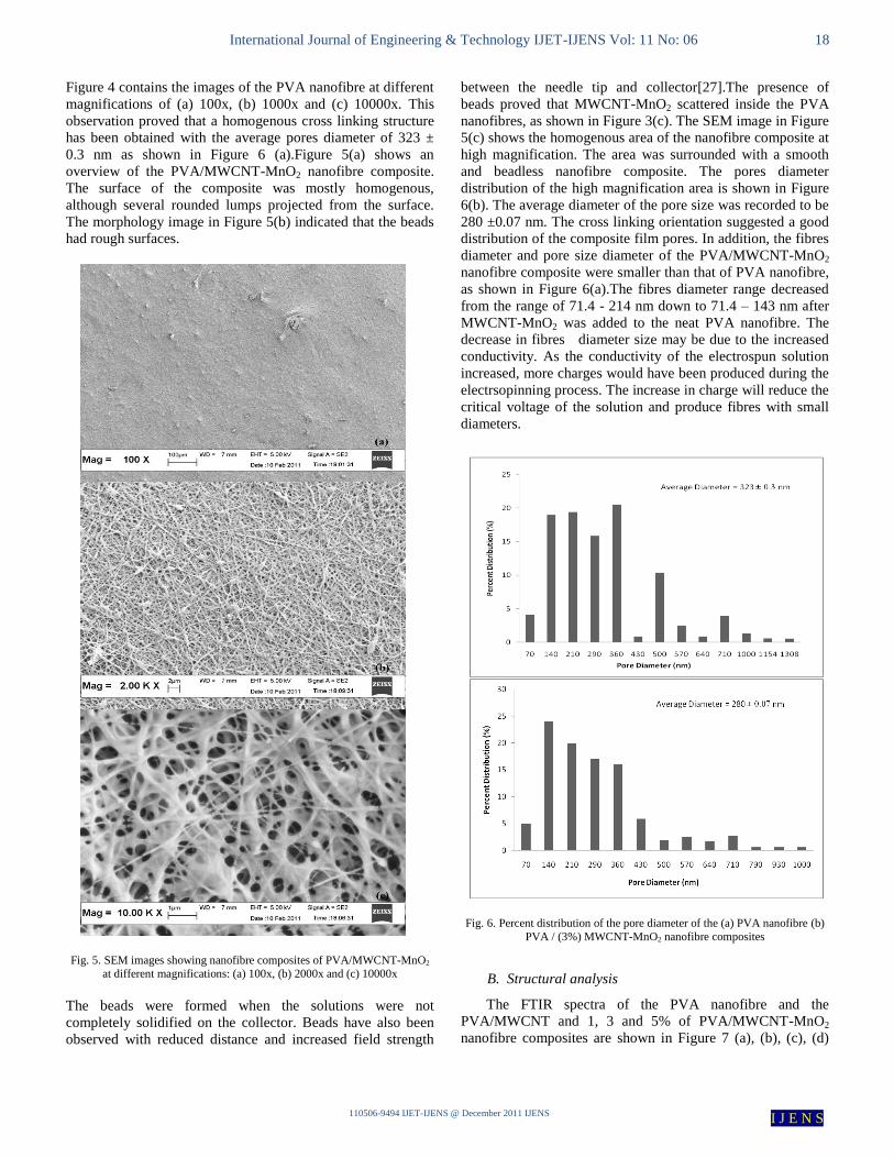
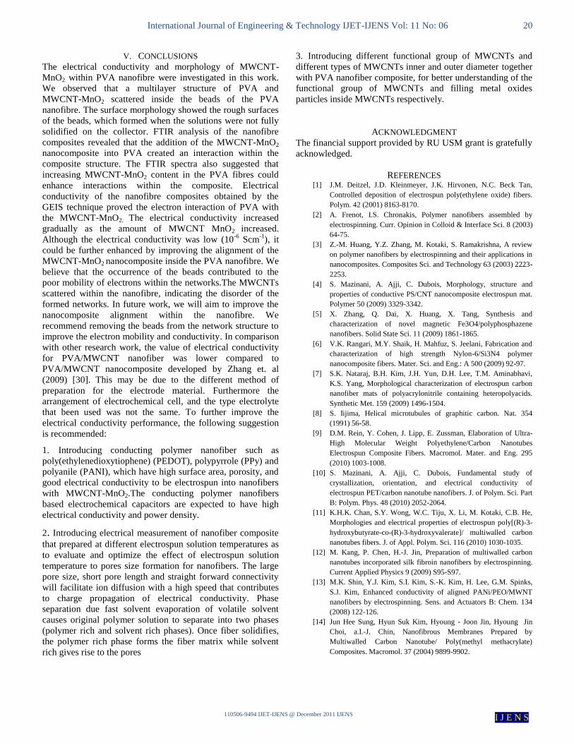
Figure 4 contains the images of the PVA nanofibre at different
magnifications of (a) 100x, (b) 1000x and (c) 10000x. This
observation proved that a homogenous cross linking structure
has been obtained with the average pores diameter of 323 ±
0.3 nm as shown in Figure 6 (a).Figure 5(a) shows an
overview of the PVA/MWCNT-MnO2 nanofibre composite.
The surface of the composite was mostly homogenous,
although several rounded lumps projected from the surface.
The morphology image in Figure 5(b) indicated that the beads
had rough surfaces.
Fig. 5. SEM images showing nanofibre composites of PVA/MWCNT-MnO2
at different magnifications: (a) 100x, (b) 2000x and (c) 10000x
The beads were formed when the solutions were not
completely solidified on the collector. Beads have also been
observed with reduced distance and increased field strength
between the needle tip and collector[27].The presence of
beads proved that MWCNT-MnO2 scattered inside the PVA
nanofibres, as shown in Figure 3(c). The SEM image in Figure
5(c) shows the homogenous area of the nanofibre composite at
high magnification. The area was surrounded with a smooth
and beadless nanofibre composite. The pores diameter
distribution of the high magnification area is shown in Figure
6(b). The average diameter of the pore size was recorded to be
280 ±0.07 nm. The cross linking orientation suggested a good
distribution of the composite film pores. In addition, the fibres
diameter and pore size diameter of the PVA/MWCNT-MnO2
nanofibre composite were smaller than that of PVA nanofibre,
as shown in Figure 6(a).The fibres diameter range decreased
from the range of 71.4 - 214 nm down to 71.4 – 143 nm after
MWCNT-MnO2 was added to the neat PVA nanofibre. The
decrease in fibres diameter size may be due to the increased
conductivity. As the conductivity of the electrospun solution
increased, more charges would have been produced during the
electrsopinning process. The increase in charge will reduce the
critical voltage of the solution and produce fibres with small
diameters.
Fig. 6. Percent distribution of the pore diameter of the (a) PVA nanofibre (b)
PVA / (3%) MWCNT-MnO2 nanofibre composites
B. Structural analysis
The FTIR spectra of the PVA nanofibre and the
PVA/MWCNT and 1, 3 and 5% of PVA/MWCNT-MnO2
nanofibre composites are shown in Figure 7 (a), (b), (c), (d)

International Journal of Engineering & Technology IJET-IJENS Vol: 11 No: 06 19
110506-9494 IJET-IJENS @ December 2011 IJENS I J E N S
and (e), respectively. Based on the FTIR wave range
reference[28], we determined that the spectra in Figure 7 (a-e)
shows a broad O–H stretching band for a hydrogen-bonded
alcohol at 3412 cm−1
and banding of CH2 groups from 2922
cm-1
to 2845 cm-1
. In Figure 7(a), we attributed the band at
1429cm-1
to (C–O-H) bending while the band at 1082 cm-1
in
Figure 6(c) is due to C-O stretching of the PVA. We also
compared pure PVA and PVA/MWCNT-MnO2
nanocomposites with different amounts of MWCNT-MnO2.
The FTIR spectra of the nanofibre films suggested the MnO2
has served as a conducting bridge to link PVA and improve
the electron interaction of the nanofibre composites. We
observed clear differences between the FTIR spectra of pure
PVA nanofibre (7(a)) with the PVA/MWCNT-MnO2
nanofibre composites (7(c), 7(d) and 7(e)).With increasing
amounts of MWCNT-MnO2, the band at 798 and 881 cm−1
gradually weakened. The band at 798 cm−1
was attributed to
the out-of-plane vibration of the O–H group, which is broad in
common alcohols [29]. As shown in Figure 7 (c-e), the content
of MWCNT-MnO2 increased and the band at 1084.29 cm−1
decreased in intensity. These results suggest an interaction
between MWCNT-MnO2 and the polymer matrix with the O–
H group.
Fig. 7. FTIR spectra of (a) a PVA nanofibre, (b) a PVA/ (1%) MWCNT
nanofibre, (c) a PVA/ (1%) MWCNT-MnO2 nanofibre, (d) PVA/ (3%)
MWCNT-MnO2 nanofibre and (e) PVA/ (5%) of MWCNT-MnO2 nanofibre
C. Electrical conductivity measurement
The direct conductivity of each sample was calculated with the
resistance value in equation (1). The electrical conductivities
of PVA/MWCNT-MnO2 nanofibre composites with different
wt% of MWCNT-MnO2 are shown in Figure 8. The
conductivity of the neat PVA nanofibre was 1.25 ×10⁻¹⁵
.The
MWCNT-MnO2 affected the nanofibre composites. The
conductivity increased with increasing amounts of MWCNT-
MnO2 incorporated into PVA. The conductivities of the
nanofibre composite at 1, 3, and 5 wt% were 5.698×10⁻⁶
,
6.689×10⁻⁶
and 6.99×10⁻⁶
Scm-1
, respectively. The increase in
conductivity was more pronounced at 1% MWCNT-MnO2.
Above 1% MWCNT-MnO2, the conductivity of the nanofibre
composites increased up to 6.99×10⁻⁶
Scm-1
at 5 wt%. Below 1
wt% of MWCNT-MnO2, the conductivity was dominated by
the PVA component. The conductivity of PVA/ MWCNT-
MnO2, compared with neat PVA, was enhanced because the
MWCNT-MnO2 served as a conducting bridge to link PVA
and improve the conductivity of the nanofibre composites.
Fig. 8. Electrochemical impedance spectroscopy of (a) PVA/MWCNT-MnO2
(5%), (b) PVA/MWCNT-MnO2 (3%), (c) PVA/MWCNT-MnO2 (1%), (d)
PVA/MWCNT and (e) PVA nanofibre.
Fig. 9. Electrical conductivity of (a) PVA/MWCNT, (b) PVA/MWCNT-
MnO2 (1%), (c) PVA/MWCNT-MnO2 (3%) and (d) PVA/MWCNT-MnO2
(5%).
IV. SCOPE AND LIMITATION
The scope of this work is to improve the electrical
conductivity of PVA/MWCNT nanofibre composite films
with MnO2 as filler synthesised using the electrospinning
process. The range of frequency studied was from 100 kHz to
0.1 Hz at 1 V of amplitude. As PVA is a non conducting
polymer, the main limitation of this study is to produce high
electrical conductivity material for electronic application. It is
believed the type of material produce from this work is able to
be used only in semi conductor applications.
4000.0 3600 3200 2800 2400 2000 1800 1600 1400 1200 1000 800 600.0
cm-1
%T
(a)
(b)
(c)
(d)
(e)
2922.11 1735.88
1429.46
3412.73
881.23
798.84
3412.73
2845.99
1084.293412.73
2845.99
1655.02
2845.99
1384.51
3412.732845.99
International Journal of Engineering & Technology IJET-IJENS Vol: 11 No: 06 20
110506-9494 IJET-IJENS @ December 2011 IJENS I J E N S
V. CONCLUSIONS
The electrical conductivity and morphology of MWCNT-
MnO2 within PVA nanofibre were investigated in this work.
We observed that a multilayer structure of PVA and
MWCNT-MnO2 scattered inside the beads of the PVA
nanofibre. The surface morphology showed the rough surfaces
of the beads, which formed when the solutions were not fully
solidified on the collector. FTIR analysis of the nanofibre
composites revealed that the addition of the MWCNT-MnO2
nanocomposite into PVA created an interaction within the
composite structure. The FTIR spectra also suggested that
increasing MWCNT-MnO2 content in the PVA fibres could
enhance interactions within the composite. Electrical
conductivity of the nanofibre composites obtained by the
GEIS technique proved the electron interaction of PVA with
the MWCNT-MnO2. The electrical conductivity increased
gradually as the amount of MWCNT MnO2 increased.
Although the electrical conductivity was low (10-6
Scm-1
), it
could be further enhanced by improving the alignment of the
MWCNT-MnO2 nanocomposite inside the PVA nanofibre. We
believe that the occurrence of the beads contributed to the
poor mobility of electrons within the networks.The MWCNTs
scattered within the nanofibre, indicating the disorder of the
formed networks. In future work, we will aim to improve the
nanocomposite alignment within the nanofibre. We
recommend removing the beads from the network structure to
improve the electron mobility and conductivity. In comparison
with other research work, the value of electrical conductivity
for PVA/MWCNT nanofiber was lower compared to
PVA/MWCNT nanocomposite developed by Zhang et. al
(2009) [30]. This may be due to the different method of
preparation for the electrode material. Furthermore the
arrangement of electrochemical cell, and the type electrolyte
that been used was not the same. To further improve the
electrical conductivity performance, the following suggestion
is recommended:
1. Introducing conducting polymer nanofiber such as
poly(ethylenedioxytiophene) (PEDOT), polypyrrole (PPy) and
polyanile (PANI), which have high surface area, porosity, and
good electrical conductivity to be electrospun into nanofibers
with MWCNT-MnO2.The conducting polymer nanofibers
based electrochemical capacitors are expected to have high
electrical conductivity and power density.
2. Introducing electrical measurement of nanofiber composite
that prepared at different electrospun solution temperatures as
to evaluate and optimize the effect of electrospun solution
temperature to pores size formation for nanofibers. The large
pore size, short pore length and straight forward connectivity
will facilitate ion diffusion with a high speed that contributes
to charge propagation of electrical conductivity. Phase
separation due fast solvent evaporation of volatile solvent
causes original polymer solution to separate into two phases
(polymer rich and solvent rich phases). Once fiber solidifies,
the polymer rich phase forms the fiber matrix while solvent
rich gives rise to the pores
3. Introducing different functional group of MWCNTs and
different types of MWCNTs inner and outer diameter together
with PVA nanofiber composite, for better understanding of the
functional group of MWCNTs and filling metal oxides
particles inside MWCNTs respectively.
ACKNOWLEDGMENT
The financial support provided by RU USM grant is gratefully
acknowledged.
REFERENCES [1] J.M. Deitzel, J.D. Kleinmeyer, J.K. Hirvonen, N.C. Beck Tan,
Controlled deposition of electrospun poly(ethylene oxide) fibers.
Polym. 42 (2001) 8163-8170.
[2] A. Frenot, I.S. Chronakis, Polymer nanofibers assembled by
electrospinning. Curr. Opinion in Colloid & Interface Sci. 8 (2003)
64-75.
[3] Z.-M. Huang, Y.Z. Zhang, M. Kotaki, S. Ramakrishna, A review
on polymer nanofibers by electrospinning and their applications in
nanocomposites. Composites Sci. and Technology 63 (2003) 2223-
2253.
[4] S. Mazinani, A. Ajji, C. Dubois, Morphology, structure and
properties of conductive PS/CNT nanocomposite electrospun mat.
Polymer 50 (2009) 3329-3342.
[5] X. Zhang, Q. Dai, X. Huang, X. Tang, Synthesis and
characterization of novel magnetic Fe3O4/polyphosphazene
nanofibers. Solid State Sci. 11 (2009) 1861-1865.
[6] V.K. Rangari, M.Y. Shaik, H. Mahfuz, S. Jeelani, Fabrication and
characterization of high strength Nylon-6/Si3N4 polymer
nanocomposite fibers. Mater. Sci. and Eng.: A 500 (2009) 92-97.
[7] S.K. Nataraj, B.H. Kim, J.H. Yun, D.H. Lee, T.M. Aminabhavi,
K.S. Yang, Morphological characterization of electrospun carbon
nanofiber mats of polyacrylonitrile containing heteropolyacids.
Synthetic Met. 159 (2009) 1496-1504.
[8] S. Iijima, Helical microtubules of graphitic carbon. Nat. 354
(1991) 56-58.
[9] D.M. Rein, Y. Cohen, J. Lipp, E. Zussman, Elaboration of Ultra-
High Molecular Weight Polyethylene/Carbon Nanotubes
Electrospun Composite Fibers. Macromol. Mater. and Eng. 295
(2010) 1003-1008.
[10] S. Mazinani, A. Ajji, C. Dubois, Fundamental study of
crystallization, orientation, and electrical conductivity of
electrospun PET/carbon nanotube nanofibers. J. of Polym. Sci. Part
B: Polym. Phys. 48 (2010) 2052-2064.
[11] K.H.K. Chan, S.Y. Wong, W.C. Tiju, X. Li, M. Kotaki, C.B. He,
Morphologies and electrical properties of electrospun poly[(R)-3-
hydroxybutyrate-co-(R)-3-hydroxyvalerate]/ multiwalled carbon
nanotubes fibers. J. of Appl. Polym. Sci. 116 (2010) 1030-1035.
[12] M. Kang, P. Chen, H.-J. Jin, Preparation of multiwalled carbon
nanotubes incorporated silk fibroin nanofibers by electrospinning.
Current Applied Physics 9 (2009) S95-S97.
[13] M.K. Shin, Y.J. Kim, S.I. Kim, S.-K. Kim, H. Lee, G.M. Spinks,
S.J. Kim, Enhanced conductivity of aligned PANi/PEO/MWNT
nanofibers by electrospinning. Sens. and Actuators B: Chem. 134
(2008) 122-126.
[14] Jun Hee Sung, Hyun Suk Kim, Hyoung - Joon Jin, Hyoung Jin
Choi, a.I.-J. Chin, Nanofibrous Membranes Prepared by
Multiwalled Carbon Nanotube/ Poly(methyl methacrylate)
Composites. Macromol. 37 (2004) 9899-9902.

International Journal of Engineering & Technology IJET-IJENS Vol: 11 No: 06 21
110506-9494 IJET-IJENS @ December 2011 IJENS I J E N S
[15] Y. Dror, W. Salalha, R.L. Khalfin, Y. Cohen, A.L. Yarin, E.
Zussman, Carbon Nanotubes Embedded in Oriented Polymer
Nanofibers by Electrospinning. Langmuir 19 (2003) 7012-7020.
[16] A. Koski, K. Yim, S. Shivkumar, Effect of molecular weight on
fibrous PVA produced by electrospinning. Mater. Lett. 58 (2004)
493-497.
[17] K.K.H. Wong, M. Zinke-Allmang, J.L. Hutter, S. Hrapovic, J.H.T.
Luong, W. Wan, The effect of carbon nanotube aspect ratio and
loading on the elastic modulus of electrospun poly(vinyl alcohol)-
carbon nanotube hybrid fibers. Carbon 47 (2009) 2571-2578.
[18] M.J. Kim, J. Lee, D. Jung, S.E. Shim, Electrospun poly(vinyl
alcohol) nanofibers incorporating PEGylated multi-wall carbon
nanotube. Synthetic Met. 160 (2010) 1410-1414.
[19] C. Bartholome, P. Miaudet, A. Derré, M. Maugey, O. Roubeau, C.
Zakri, P. Poulin, Influence of surface functionalization on the
thermal and electrical properties of nanotube-PVA composites.
Composites Sci. and Technology 68 (2008) 2568-2573.
[20] P. Miaudet, C. Bartholome, A. Derré, M. Maugey, G. Sigaud, C.
Zakri, P. Poulin, Thermo-electrical properties of PVA-nanotube
composite fibers. Polymer 48 (2007) 4068-4074.
[21] Kiamahalleh, M.V, Sata S.A, S. B, a.Z. S.H.S, A Comparative
Study on The Electrochemical Performance of Nickel Oxide and
Manganese Oxide Nanocomposite Based Multiwalled Carbon
Nanotube. World Appl. Sci. J. 6 (2009) 711-718.
[22] S.I.A. Razak, A.L. Ahmad, S.H.S. Zein, A.R. Boccaccini, MnO2-
filled multiwalled carbon nanotube/polyaniline nanocomposites
with enhanced interfacial interaction and electronic properties. Scr.
Mater. 61 (2009) 592-595.
[23] Zein S.H.S, Yeoh L.C, Chai S.P, M. A.R, a.M. M.E.M, Synthesis
of Manganese Oxide / Carbon Nanotube Composites Using Wet
Chemical Method. Mater. Process. Technology 190 (2007) 402-
405.
[24] A. Koski, K. Yim., and, S. Shivkumar, Effect of Molecular Weight
on Fibrous PVA Produced by Electrospinning. Materials Letters 58
(2003) 493-497.
[25] M.H Harun, S. Elias, A.Kassim, M.Y Hussain, I.S. Mustafa,
a.M.A.A. Omer, Temperature depence of AC electrical
conductivity of PVA-Ppy-FeCl3 composite polymer film. Malays.
Polym. J. 3 (2008) 24-31.
[26] N. Fouquet, C. Doulet, C. Nouillant, G. Dauphin-Tanguy, B. Ould-
Bouamama, Model based PEM fuel cell state-of-health monitoring
via ac impedance measurements. J. of Power Sources 159 (2006)
905-913.
[27] J. Fang, H. Wang, H. Niu, T. Lin, X. Wang, Evolution of Fiber
Morphologies during Poly (acrylonitrile) Electrospinning.
Macromol. Symposia 287 (2010) 155-161.
[28] B. Smith., Infrared spectral interpretation, a systematic approach.
New York CRC press. Infrared spectral interpretation, a systematic
approach. New York CRC press (1998).
[29] J. Bai, Y. Li, S. Yang, J. Du, S. Wang, J. Zheng, Y. Wang, Q.
Yang, X. Chen, X. Jing, A simple and effective route for the
preparation of poly(vinylalcohol) (PVA) nanofibers containing
gold nanoparticles by electrospinning method. Solid State
Commun. 141 (2007) 292-295.
[30] J. Zhang, M. Mine, D. Zhu, M. Matsuo., Electrical and dielectric
behaviour and their origins in three dimension polyvinyl
alcohol/MWCNT composites with low percolation threshold.
Carbon 47 (2009) 1311-1320.