Improved Damper Cage Design for Salient-Pole Synchronous...
11
Improved Damper Cage Design for Salient-Pole Synchronous Generators Abstract—The benefits of implementing a damper winding in salient-pole, synchronous generators are widely known and well consolidated. It is also well known that such a winding incurs extra losses in the machine due to a number of reasons. In order to improve the overall efficiency and performance of classical salient- pole, wound field, synchronous generators that employ the tradi- tional damper cage, an improved amortisseur winding topology that reduces the inherent loss is proposed and investigated in this paper. This is essential in order to meet modern power quality requirements and to improve the overall performance of such ’classical’ machines. The new topology addresses the requirements for lower loss components without compromising the acceptable values of the output voltage total harmonic distortion and achieves this by having a modulated damper bar pitch. As vessel for studying the proposed concept, a 4MVA, salient-pole, synchronous generator is considered. A finite element model of this machine is first built and then validated against experimental results. The validated model is then used to investigate the proposed concept with an optimal solution being achieved via the implementation of a genetic algorithm optimization tool. Finally, the performance of the optimised machine is compared to the original design both at steady state and transient operating conditions. I. I NTRODUCTION Due to its excellent characteristics and proven performance capability, the salient-pole, field wound, synchronous generator (SG) has a long history of utilisation in the field of power generation [1], [2]. Although these ’classical’ electrical ma- chines have been extensively studied and implemented, today there is an interest in revamping their design and development, partly due to the ever-increasing requirements in terms of power quality standards, efficiency and grid compliance and partly due to advances in materials and manufacturing techniques. Also, the significant improvements in the computational resources allow the utilisation of modern design techniques and tools such as multi-physics modelling [3] and virtual prototyping [4]. In order to consider efficiency and power quality constraints, particular focus in recent years has been given to the functional behaviour and design features of the damper winding. This consists of bars placed in slots in the pole faces and connected together at each end. The end conductors in a complete damper winding are closed rings (or sometimes end laminations) con- necting the bars of all the poles, while in an incomplete damper winding they are electrically discontinued between poles. Com- plete damper windings are similar to the squirrel-cage of an induction machine [5]. The main reasons for providing a damper cage on salient-pole synchronous generators, as summarized in [6], are • providing starting torque for synchronous motors, con- densers and converters; • suppress hunting due to the pulsating torque of the engines; • damping oscillations caused by aperiodic shocks, such as short-circuits; • balancing terminal voltages during unbalanced loading; • preventing overheating of the pole tips of single-phase generators; • providing braking torque on a generator during an asym- metrical fault; • providing additional torque for synchronizing generators; • reducing the stress on the insulation of the field winding during current surges in the armature windings; • preventing distortion of voltage waveform; in other words, to suppress harmonics. Additional losses in the damper winding are due to parasitic harmonics in the air-gap flux density. As stated in [7], these harmonics are generated by the following: • Tooth-ripple, due to the open slot structure typical of high- voltage machines; • Armature reaction magneto-motive force, which causes parasitic harmonics on the rotor surface when currents flow in the stator windings; • Unbalanced air-gap, which can induce high bar currents. Traditionally, the design of damper windings has been done by means of conventional methods which combine theoretical and empirical techniques. Early works focused on the prediction of the damper-bar currents with the classical dq equivalent circuit approach [8], [9]. With the same purpose, permeance models based on Fourier expansion are used in [10] and [11]. In [7] an innovative numerical integration method is proposed and also compared with the traditional dq-axis approach with very posi- tive results. Although the worth of these traditional techniques is well known and consolidated, with the recent advancements in computational capabilities, a significant shift towards numerical methods, such as finite-element (FE) and computational fluid dynamics [12], [13], allows for improved accuracy and extra degrees of freedom in the design process. Due to this, today there is an increasing interest in the damper winding designs (and SGs in general [14]), as this can be very beneficial to the overall SG performance. This is very important especially when considering the possibility to investigate the machine operation both in steady-state and in transient conditions. In particular, ”complete” and ”incomplete” end connections are analysed in [15] and [16], where the effects on the generator performance of various damper cage designs were investigated. In [17] and [18], FE analyses are used to predict and optimize the no-load voltage waveform. For example, [19] shows how improvements in the voltage output shape are achieved by inducing additional currents in the bars of the damper winding at the cost of increased losses and thermal issues. In this work, a new damper cage topology is proposed to address the requirements for the output voltage Total Harmonic Distortion (THD), without compromising the power loss associ- ated with this winding. The proposed techniques are considered on an existing machine platform in the form of a 4MVA SG. The SG in question is presented in Section II, where it can be seen how this machine exhibits high rotor losses, making it an ideal vessel for the work proposed in this project. As a first step, a complete FE analysis of the current machine is done and compared with available experimental results, obtained from the prototype shown in Fig. 19. The FE model is then used to propose, investigate and validate a number of techniques to improve the overall SG performance. However, the main objective of this work is to provide an alternative solution to the state-of-the-art, aimed at reducing damper winding loss at
Transcript of Improved Damper Cage Design for Salient-Pole Synchronous...
Improved Damper Cage Design for Salient-PoleSynchronous Generators
Abstract—The benefits of implementing a damper winding insalient-pole, synchronous generators are widely known and wellconsolidated. It is also well known that such a winding incursextra losses in the machine due to a number of reasons. In order toimprove the overall efficiency and performance of classical salient-pole, wound field, synchronous generators that employ the tradi-tional damper cage, an improved amortisseur winding topologythat reduces the inherent loss is proposed and investigated in thispaper. This is essential in order to meet modern power qualityrequirements and to improve the overall performance of such’classical’ machines. The new topology addresses the requirementsfor lower loss components without compromising the acceptablevalues of the output voltage total harmonic distortion and achievesthis by having a modulated damper bar pitch. As vessel forstudying the proposed concept, a 4MVA, salient-pole, synchronousgenerator is considered. A finite element model of this machineis first built and then validated against experimental results. Thevalidated model is then used to investigate the proposed conceptwith an optimal solution being achieved via the implementation ofa genetic algorithm optimization tool. Finally, the performance ofthe optimised machine is compared to the original design both atsteady state and transient operating conditions.
I. INTRODUCTION
Due to its excellent characteristics and proven performancecapability, the salient-pole, field wound, synchronous generator(SG) has a long history of utilisation in the field of powergeneration [1], [2]. Although these ’classical’ electrical ma-chines have been extensively studied and implemented, todaythere is an interest in revamping their design and development,partly due to the ever-increasing requirements in terms of powerquality standards, efficiency and grid compliance and partly dueto advances in materials and manufacturing techniques. Also,the significant improvements in the computational resourcesallow the utilisation of modern design techniques and tools suchas multi-physics modelling [3] and virtual prototyping [4].
In order to consider efficiency and power quality constraints,particular focus in recent years has been given to the functionalbehaviour and design features of the damper winding. Thisconsists of bars placed in slots in the pole faces and connectedtogether at each end. The end conductors in a complete damperwinding are closed rings (or sometimes end laminations) con-necting the bars of all the poles, while in an incomplete damperwinding they are electrically discontinued between poles. Com-plete damper windings are similar to the squirrel-cage of aninduction machine [5]. The main reasons for providing a dampercage on salient-pole synchronous generators, as summarized in[6], are• providing starting torque for synchronous motors, con-
densers and converters;• suppress hunting due to the pulsating torque of the engines;• damping oscillations caused by aperiodic shocks, such as
short-circuits;• balancing terminal voltages during unbalanced loading;• preventing overheating of the pole tips of single-phase
generators;• providing braking torque on a generator during an asym-
metrical fault;• providing additional torque for synchronizing generators;
• reducing the stress on the insulation of the field windingduring current surges in the armature windings;
• preventing distortion of voltage waveform; in other words,to suppress harmonics.
Additional losses in the damper winding are due to parasiticharmonics in the air-gap flux density. As stated in [7], theseharmonics are generated by the following:
• Tooth-ripple, due to the open slot structure typical of high-voltage machines;
• Armature reaction magneto-motive force, which causesparasitic harmonics on the rotor surface when currents flowin the stator windings;
• Unbalanced air-gap, which can induce high bar currents.
Traditionally, the design of damper windings has been done bymeans of conventional methods which combine theoretical andempirical techniques. Early works focused on the prediction ofthe damper-bar currents with the classical dq equivalent circuitapproach [8], [9]. With the same purpose, permeance modelsbased on Fourier expansion are used in [10] and [11]. In [7] aninnovative numerical integration method is proposed and alsocompared with the traditional dq-axis approach with very posi-tive results. Although the worth of these traditional techniques iswell known and consolidated, with the recent advancements incomputational capabilities, a significant shift towards numericalmethods, such as finite-element (FE) and computational fluiddynamics [12], [13], allows for improved accuracy and extradegrees of freedom in the design process. Due to this, todaythere is an increasing interest in the damper winding designs(and SGs in general [14]), as this can be very beneficial to theoverall SG performance. This is very important especially whenconsidering the possibility to investigate the machine operationboth in steady-state and in transient conditions. In particular,”complete” and ”incomplete” end connections are analysed in[15] and [16], where the effects on the generator performanceof various damper cage designs were investigated. In [17] and[18], FE analyses are used to predict and optimize the no-loadvoltage waveform. For example, [19] shows how improvementsin the voltage output shape are achieved by inducing additionalcurrents in the bars of the damper winding at the cost ofincreased losses and thermal issues.
In this work, a new damper cage topology is proposed toaddress the requirements for the output voltage Total HarmonicDistortion (THD), without compromising the power loss associ-ated with this winding. The proposed techniques are consideredon an existing machine platform in the form of a 4MVA SG.The SG in question is presented in Section II, where it canbe seen how this machine exhibits high rotor losses, making itan ideal vessel for the work proposed in this project. As a firststep, a complete FE analysis of the current machine is done andcompared with available experimental results, obtained fromthe prototype shown in Fig. 19. The FE model is then usedto propose, investigate and validate a number of techniquesto improve the overall SG performance. However, the mainobjective of this work is to provide an alternative solution tothe state-of-the-art, aimed at reducing damper winding loss at
steady-state operation while keeping the no-load voltage THDunder permissible limits. A Genetic Algorithm (GA) basedoptimization is carried out in order to achieve an optimalsolution.
II. ANALYSIS AND VALIDATION OF THE MODEL OF THE SGTEST PLATFORM
The salient-pole SG under analysis is a four pole alternatordesigned for standalone power applications. The machine hasa rated apparent power of 4MVA at 0.8 power factor. Thegenerator is designed to provide a three-phase output voltageof 11kV at 50Hz. Some of the major features of the SG understudy are as follows:
• the stator is laminated and has a open-slot structure;• stator coils are grouped in 2 parts, having different number
of turns to reach a certain desired magneto-motive force;• there are no parallel circuits on the stator windings;• the stator core is equipped with radial ventilating ducts
along the axial direction; these reduce the active materialof the machine but improve cooling and airflow;
• the rotor is also laminated and made by the same electro-magnetic steel as the stator laminations;
• the ratio between the rotor diameter (in correspondence ofthe minimum airgap) and the axial length is 0.5;
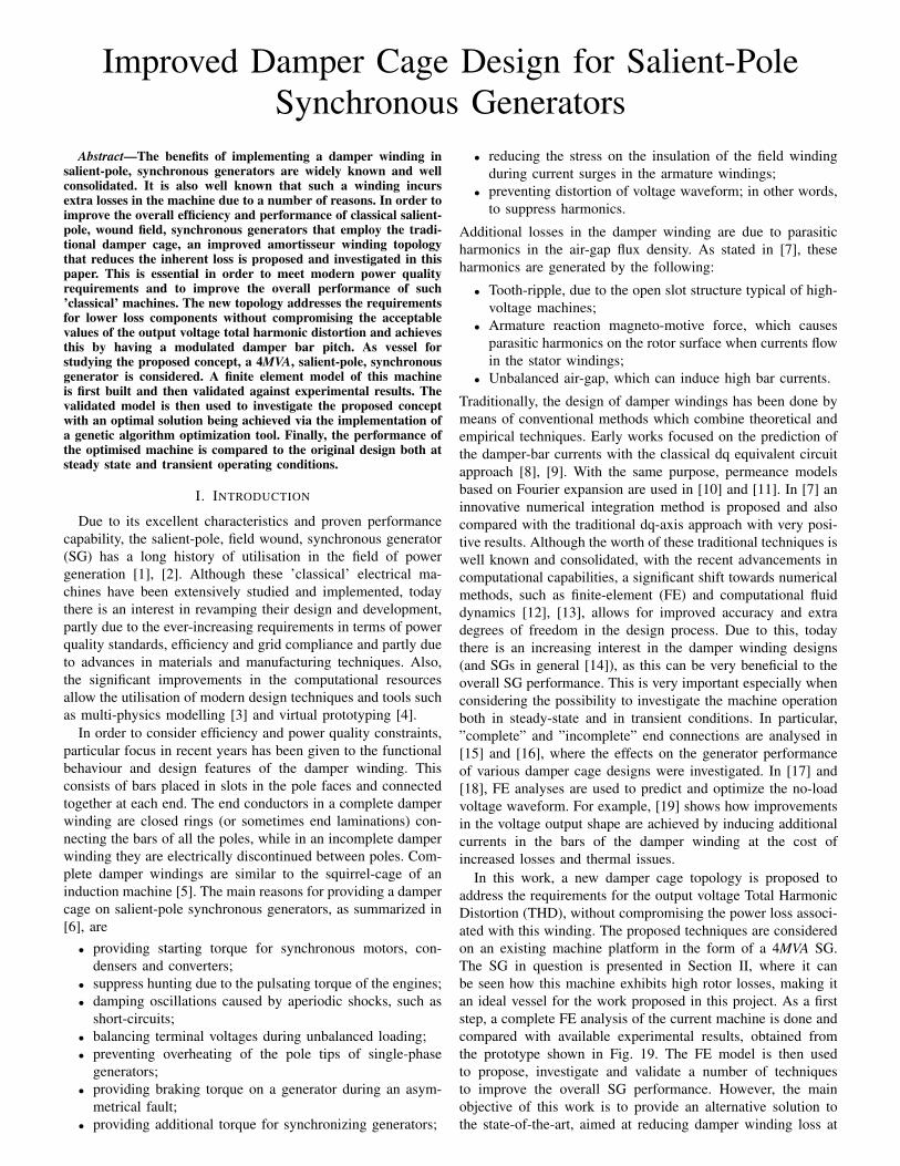
• the damper cage on the rotor is displaced around the polaraxis in alternating directions on each pole, as shown inFig. 1, in order to improve the harmonic content of theoutput voltage waveform in the absence of rotor or statorskewing.
In SGs, the presence of ventilating ducts along the axial length,the damper winding, the rotor laminations support bars and theirrelated stacking issues make the machine very complex to modeland analyse. Other critical aspects are the leakage fluxes dueto the end-windings and the presence of the end aluminiumlaminations needed to give continuity to the damper cage.To consider such machine aspects, a number of compensationfactors are included in the FE model. In particular, whilst anycontact between bars and laminations are considered negligiblefor the sake of this study, end connections are accounted forthrough circuital lumped resistances and calculated taking intoaccount shape and thickness of the end aluminium laminations.This allows for a significant increase in the model’s accuracy.Also, considering that the main investigation focuses on thedamper windings, it was considered essential to model theamortisseur bars as accurately as possible. In fact, each baris modelled as a solid conductor to take into account the skineffect due to the higher order slot harmonics [20], [21].
Damper bars
d - axisd - axis
Pole 1 Pole 2
Fig. 1. Actual rotor topology with damper cage displaced around the polar axis(d-axis).
A. No-Load and Short-Circuit Characteristics
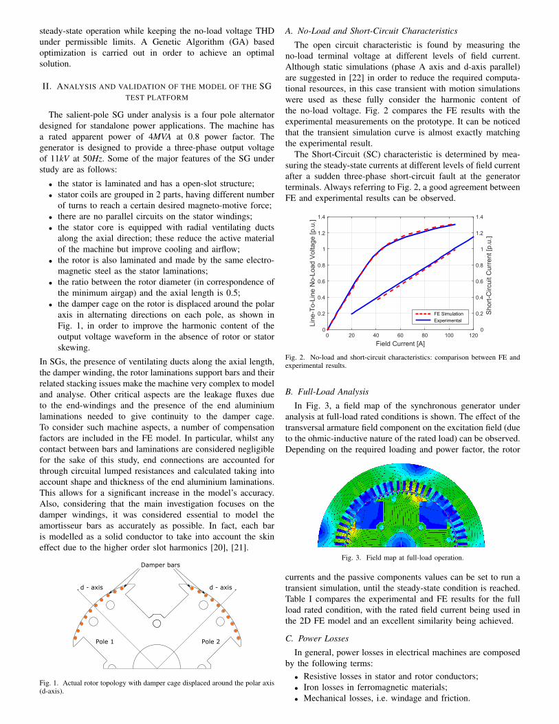
The open circuit characteristic is found by measuring theno-load terminal voltage at different levels of field current.Although static simulations (phase A axis and d-axis parallel)are suggested in [22] in order to reduce the required computa-tional resources, in this case transient with motion simulationswere used as these fully consider the harmonic content ofthe no-load voltage. Fig. 2 compares the FE results with theexperimental measurements on the prototype. It can be noticedthat the transient simulation curve is almost exactly matchingthe experimental result.
The Short-Circuit (SC) characteristic is determined by mea-suring the steady-state currents at different levels of field currentafter a sudden three-phase short-circuit fault at the generatorterminals. Always referring to Fig. 2, a good agreement betweenFE and experimental results can be observed.
Field Current [A]0 20 40 60 80 100 120
Line
-To-
Line
No-
Load
Vol
tage
[p.u
.]
0
0.2
0.4
0.6
0.8
1
1.2
1.4
Sho
rt-C
ircu
it C
urre
nt [p
.u.]
0
0.2
0.4
0.6
0.8
1
1.2
1.4
FE Simulation
Experimental
Fig. 2. No-load and short-circuit characteristics: comparison between FE andexperimental results.
B. Full-Load Analysis
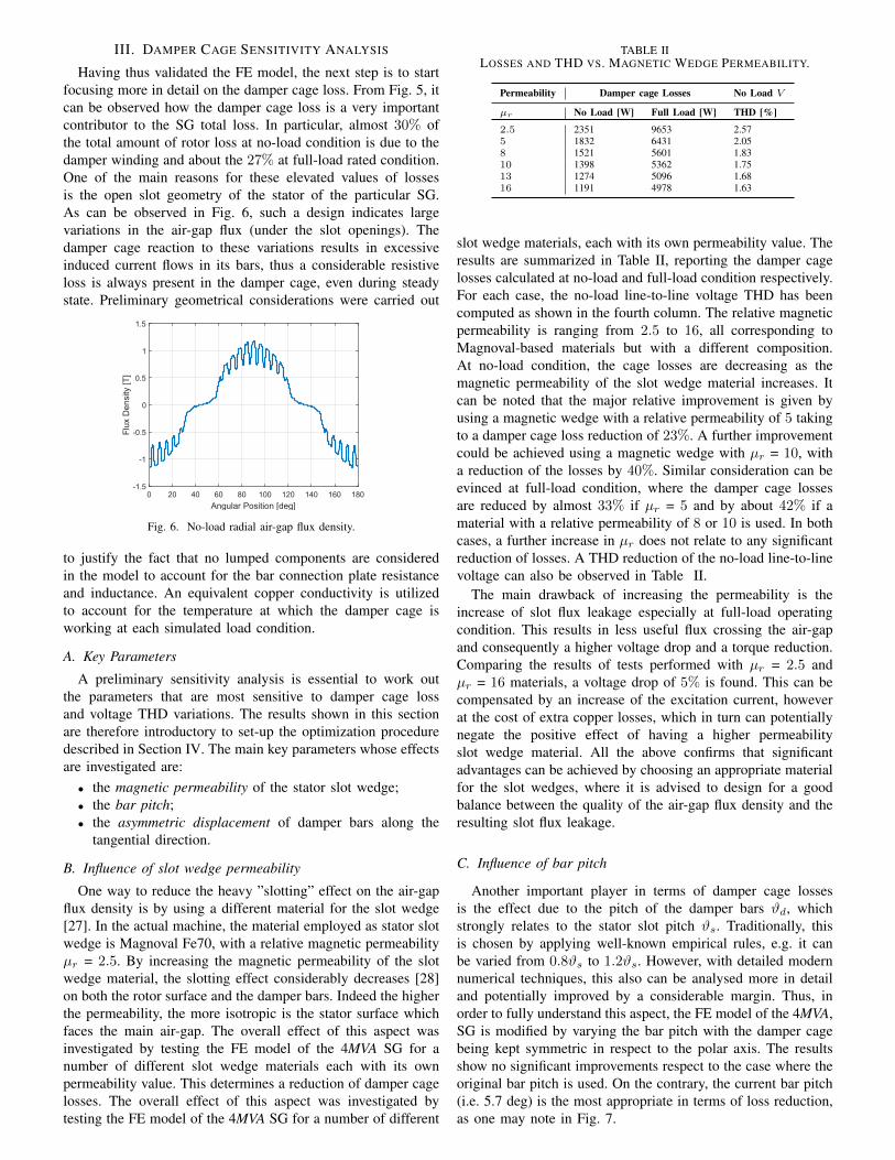
In Fig. 3, a field map of the synchronous generator underanalysis at full-load rated conditions is shown. The effect of thetransversal armature field component on the excitation field (dueto the ohmic-inductive nature of the rated load) can be observed.Depending on the required loading and power factor, the rotor
Fig. 3. Field map at full-load operation.
currents and the passive components values can be set to run atransient simulation, until the steady-state condition is reached.Table I compares the experimental and FE results for the fullload rated condition, with the rated field current being used inthe 2D FE model and an excellent similarity being achieved.
C. Power Losses
In general, power losses in electrical machines are composedby the following terms:• Resistive losses in stator and rotor conductors;• Iron losses in ferromagnetic materials;• Mechanical losses, i.e. windage and friction.

TABLE IFULL-LOAD RESULTS
Electromagnetic FE Experimental PercentageQuantities Results Results Error
Field Current 143.7 A 143.7 A 0 %
Load V oltage 10998 V 11000 V 0.02 %
Phase Current 230.2 A 233.6 A 1.46 %
Power Factor 0.802 0.8 0.25 %
Real Power 3.51 kW 3.56 kW 1.46 %
The SG being considered in this paper comprises the presenceof ventilating ducts on the stator. Thus, in order to considerthe parts of the windings which are present along these ducts,an additional lumped resistance is added to the model. Thisalso is used to take into account the end-winding effects, whichcan be important especially when using 2D models. Simplecorrections are included to account for the temperature effectson the copper conductivity. Based on this, it can be inferred thatthe resistances considered in the FE model are very close to theexperimental ones. Therefore, while very small differences aredetected for the field winding losses, the discrepancy betweenFE and experimentally determined currents reflects on the statorresistive loss. Fig. 4 shows a comparison between FE and exper-imental copper losses, at different loadings and power factors,where the percentage error at rated full-load condition is 5.46%for the stator loss. Core losses are experimentally measured at
100%1 PF
Loading and Power Factor
100%0.8 PF
50%1 PF
50%0.8 PF
Loss
es [k
W]
45
50
0
5
10
15
20
35
40
30
25
Stator
Rotor
Exp
Exp
Exp
Exp
Sim
Sim
Sim
Sim
Fig. 4. Copper losses at different load levels and power factors: comparisonbetween FE and experimental results.
no-load and then assumed approximately constant for all loadlevels and power factors. Traditionally only the total core lossis determined as any localisation exercise to determine wherethe loss actually is (rotor or stator or damper) is very difficultto do. Although damper winding losses are of ohmic-resistivenature, they are included in the experimentally measured values.Numerical methods usually employ the Steinmetz equation [23]to determine iron losses. In this work, an algorithm based onSteinmetz equations but extended to all the harmonics [24] isproposed and implemented. Hence, surface losses due to theslot harmonics are properly considered over the whole amountof iron loss. The computation algorithm of the iron losses canbe summarised in the followings:• A transient with motion 2D finite-element analysis is
performed.• From the magnetic field solution, the flux-density wave-
form is extracted corresponding to an electric cycle foreach element from the iron regions, i.e. the stator and rotorsteel.
• The Fourier-series decomposition is applied for all the flux-density waveforms. The first 100 harmonics are considered,in order to account for the slotting effect on the losscomputation.
• The following equations are then used to compute thehysteresis and eddy current components in each elementof the iron regions:
Piron = Physt + Peddy (1)
Physt = kh
N∑i=1
(if)Bαi (2)
Peddy = ke
N∑i=1
(if)2B2i (3)
where f is the frequency, B the peak flux density, kh andke are the hysteresis and the eddy current loss coefficientsrespectively, and α is the Steinmetz constant. These co-efficients are determined through curve fitting techniques,by using the data available from test previously carriedout on an Epstein frame for obtaining the loss contributionseparation.
• The summation of all the losses per element gives the totaliron loss.
In Fig. 5, the losses computed by means of this algorithm,developed in [24] for different applications, can be observedat various loadings and power factors. It can be observed thatiron losses are essentially constant in relation to loading andpower factor, while damper cage loss significantly varies withrespect to the same aspects. In order to be coherent with the
Loading and Power Factor
100%1PF
100%0.8PF
50%1PF
50%0.8PF
No-Load
Loss
es [k
W]
0
5
10
15
20
25
30Damper Cage
Stator
Rotor
Experimental
Exp
erim
enta
l
Fig. 5. Iron losses at different load levels and power factors.
experimental loss determination, the measured and predictedlosses are compared only for the no-load condition. A very goodsimilarity between FE and experimental results is observed, witha percentage error of less than 13% being achieved.
D. Conclusive considerations on the FE model
Although a 3D model [25], [26] would be ideal for theelectromagnetic analysis of the generator described in thissection, all the above confirms the validity of the built 2D FEmodel of the 4MVA salient-pole SG. As can be observed, theobtained FE results, when compared to the experimental ones,give an accurate match at each load condition. Fig. 2 shows acomparison in terms of no-load and short-circuit characteristics.From Table I, a very good agreement can be observed in termsof full-load results. The FE and experimental copper and ironlosses are also compared and successfully validated for differentloadings and power factors.
III. DAMPER CAGE SENSITIVITY ANALYSIS
Having thus validated the FE model, the next step is to startfocusing more in detail on the damper cage loss. From Fig. 5, itcan be observed how the damper cage loss is a very importantcontributor to the SG total loss. In particular, almost 30% ofthe total amount of rotor loss at no-load condition is due to thedamper winding and about the 27% at full-load rated condition.One of the main reasons for these elevated values of lossesis the open slot geometry of the stator of the particular SG.As can be observed in Fig. 6, such a design indicates largevariations in the air-gap flux (under the slot openings). Thedamper cage reaction to these variations results in excessiveinduced current flows in its bars, thus a considerable resistiveloss is always present in the damper cage, even during steadystate. Preliminary geometrical considerations were carried out
Angular Position [deg]0 20 40 60 80 100 120 140 160 180
Flu
x D
ensi
ty [T
]
-1.5
-1
-0.5
0
0.5
1
1.5
Fig. 6. No-load radial air-gap flux density.
to justify the fact that no lumped components are consideredin the model to account for the bar connection plate resistanceand inductance. An equivalent copper conductivity is utilizedto account for the temperature at which the damper cage isworking at each simulated load condition.
A. Key Parameters
A preliminary sensitivity analysis is essential to work outthe parameters that are most sensitive to damper cage lossand voltage THD variations. The results shown in this sectionare therefore introductory to set-up the optimization proceduredescribed in Section IV. The main key parameters whose effectsare investigated are:• the magnetic permeability of the stator slot wedge;• the bar pitch;• the asymmetric displacement of damper bars along the
tangential direction.
B. Influence of slot wedge permeability
One way to reduce the heavy ”slotting” effect on the air-gapflux density is by using a different material for the slot wedge[27]. In the actual machine, the material employed as stator slotwedge is Magnoval Fe70, with a relative magnetic permeabilityµr = 2.5. By increasing the magnetic permeability of the slotwedge material, the slotting effect considerably decreases [28]on both the rotor surface and the damper bars. Indeed the higherthe permeability, the more isotropic is the stator surface whichfaces the main air-gap. The overall effect of this aspect wasinvestigated by testing the FE model of the 4MVA SG for anumber of different slot wedge materials each with its ownpermeability value. This determines a reduction of damper cagelosses. The overall effect of this aspect was investigated bytesting the FE model of the 4MVA SG for a number of different
TABLE IILOSSES AND THD VS. MAGNETIC WEDGE PERMEABILITY.
Permeability Damper cage Losses No Load V
µr No Load [W] Full Load [W] THD [%]
2.5 2351 9653 2.575 1832 6431 2.058 1521 5601 1.8310 1398 5362 1.7513 1274 5096 1.6816 1191 4978 1.63
slot wedge materials, each with its own permeability value. Theresults are summarized in Table II, reporting the damper cagelosses calculated at no-load and full-load condition respectively.For each case, the no-load line-to-line voltage THD has beencomputed as shown in the fourth column. The relative magneticpermeability is ranging from 2.5 to 16, all corresponding toMagnoval-based materials but with a different composition.At no-load condition, the cage losses are decreasing as themagnetic permeability of the slot wedge material increases. Itcan be noted that the major relative improvement is given byusing a magnetic wedge with a relative permeability of 5 takingto a damper cage loss reduction of 23%. A further improvementcould be achieved using a magnetic wedge with µr = 10, witha reduction of the losses by 40%. Similar consideration can beevinced at full-load condition, where the damper cage lossesare reduced by almost 33% if µr = 5 and by about 42% if amaterial with a relative permeability of 8 or 10 is used. In bothcases, a further increase in µr does not relate to any significantreduction of losses. A THD reduction of the no-load line-to-linevoltage can also be observed in Table II.
The main drawback of increasing the permeability is theincrease of slot flux leakage especially at full-load operatingcondition. This results in less useful flux crossing the air-gapand consequently a higher voltage drop and a torque reduction.Comparing the results of tests performed with µr = 2.5 andµr = 16 materials, a voltage drop of 5% is found. This can becompensated by an increase of the excitation current, howeverat the cost of extra copper losses, which in turn can potentiallynegate the positive effect of having a higher permeabilityslot wedge material. All the above confirms that significantadvantages can be achieved by choosing an appropriate materialfor the slot wedges, where it is advised to design for a goodbalance between the quality of the air-gap flux density and theresulting slot flux leakage.
C. Influence of bar pitch
Another important player in terms of damper cage lossesis the effect due to the pitch of the damper bars ϑd, whichstrongly relates to the stator slot pitch ϑs. Traditionally, thisis chosen by applying well-known empirical rules, e.g. it canbe varied from 0.8ϑs to 1.2ϑs. However, with detailed modernnumerical techniques, this also can be analysed more in detailand potentially improved by a considerable margin. Thus, inorder to fully understand this aspect, the FE model of the 4MVA,SG is modified by varying the bar pitch with the damper cagebeing kept symmetric in respect to the polar axis. The resultsshow no significant improvements respect to the case where theoriginal bar pitch is used. On the contrary, the current bar pitch(i.e. 5.7 deg) is the most appropriate in terms of loss reduction,as one may note in Fig. 7.

Bar Pitch [deg]5 5.2 5.4 5.6 5.8 6
Loss
es [W
]
0
500
1000
1500
2000
2500
3000
Fig. 7. No-load damper cage losses vs. bar pitch.
D. Influence of asymmetric bar displacement
In order to improve the voltage total harmonic distortion, thedamper cage can be displaced by a particular angle, usuallychosen as a fraction of the stator slot pitch, in respect tothe polar axis. Some considerations on improved design andanalysis of this aspect are presented in [29], with main focuson the improvement of the machine voltage THD, with noconsideration for reducing losses. This geometrical feature canbe seen in Fig. 8, where the damper bars are displaced inan asymmetric form over the rotor poles. In the case of thegenerator being studied in this paper, the actual configurationis the one shown in Fig. 8a). In order to investigate the effectsthat the asymmetry has on both the total amount of losses inthe damper cage and voltage THD, a number of tests usingdifferent positions along the azimuthal direction are performed.In particular, the damper cage angle are varied from -1.68deg (corresponding to the original displacement) to +1.68 deg(corresponding to the position shown in Fig. 8 c). From Fig. 9and 10, it can be observed that a symmetrical configuration(position 0 deg, as shown Fig. 8 b) presents the lowest cageloss respect to the other tangential positions, but at the sametime results in a THD of about 7%, which for the application athand is not acceptable. On the other side, the original damperwinding position is the only one that achieves a THD lowerthan 3%. Even considering the importance of having a lowTHD for this application, this is still not an optimal solutionbecause, as shown in Fig. 9, it also presents considerable damperwinding ohmic losses, resulting in more heat generation andconsequently a deterioration of the total machine efficiency.In particular, with respect to the symmetrical case, losses areincreased by 15%.
d - axis
Pole 1
a)
0
b)
c)
0
-1.68
+1.68
Fig. 8. Different damper cage positions shifted by: a) -1.68 deg, b) 0 deg(symmetrical case) and c) +1.68 deg with respect to the polar axis.
Considering all the above, then it is clear that while the orig-
Position [deg]-1.68 0 +1.68
Loss
es [W
]
0
500
1000
1500
2000
2500
3000
Fig. 9. No-load damper cage loss vs. tangential position.
Position [deg]-1.68 0 +1.68
TH
D [%
]
0
1
2
3
4
5
6
7
8
Fig. 10. No-load voltage THD vs. tangential position.
inal design of the damper cage meets some of the requirements(THD < 3%), significant margins of improvement (mainly interms of reducing losses) can be achieved.
IV. MODULATED DAMPER CAGE OPTIMIZATION
All the above studies show that for certain aspects there issignificant room for improvement by modifying the design ofthe damper cage windings. As a means to reduce these lossesin the damper winding, whilst maintaining the voltage THD atan acceptable limit, it is proposed to modify the positioning ofthe bars in the context of having a modulated bar pitch. Thisconcept consists of having unconventionally displaced damperbars along the salient pole. In other words, when the bar pitchβi is constant and equal to βi+1, with i = 0, .., 9, the dampercage is equally distributed. When the bar pitch is variable,with βi 6= βi+1, the winding can be called ”modulated dampercage” and looks like the scheme illustrated in Fig. 13b). Byapplying this solution to the particular SG analysed, the irregulardamper bar pitch interacts with the stator open slot structurein such a way that the air-gap parasitic harmonics are reduced.Although the concept of having asymmetrical windings has beenalready implemented in asynchronous machines [30], such amethodology has not been applied to address losses and THDimprovements in SGs.
A. Preliminary Analytical Considerations
The equivalent circuit methodology is a classical approach formodelling electromagnetic phenomena in electrical machines. Inparticular, SGs models which include the rotor damper windingconsist of ’m + b + 2’ circuits magnetically coupled to eachother, where m and b are the number of stator phases and rotorbars, respectively. It is common to model the damper cage as’b+1’ loops [31], thus allowing to derive the voltage equationsin the matrix form as given in (4), where the vector i represents

the currents flowing in the phases and ψ the fluxes linking withthe phases.
v = Ri+dψ
dt(4)
Neglecting the saturation effects in the soft magnetic parts ofthe machine, the analysis can then be dealt with as magneticallylinear and (4) can be developed and described by (5).
v = Ri+ (δL(α)
δαi)dα
dt+ L(α)
di
dt(5)
In equation (5), α is the mechanical variable associated withthe rotor position, and R and L are (m+ b+ 1) ∗ (m+ b+ 1)matrices containing all the resistances, and the self- and mutual-inductances that characterise the machine. It can also observedthat, if the phase resistances and the state variables (i.e. currentsand position) are known, then the machine performance isdirectly related to the inductance matrix.
An expression for the inductance, based on the application ofthe winding function method [32], is provided in (6) [33], wherel is the axial length of the machine, λ the angular referenceframe locked to the rotor and normalised over the electricalperiod and NE the vector of the equivalent winding functionsof the phases. The equivalent winding function NEj(λ, α) ofthe generic phase j is defined by the difference between theknown winding function Nj(λ, α) and its mean value weightedover the equivalent permeability function µE(λ, α), which isgiven in (7).
L(α) = l
∫ 1
0
µE(λ, α) NE(λ, α) NTE (λ, α) dλ (6)
µE(λ, α) = µ02πrG(λ, α)
εG(λ, α)(7)
In (7), µ0 is the permeability of the free space, and rG(λ, α) andεG(λ, α) represent the air-gap radius and thickness, respectivelyalong the tangential direction. Hence, (7) contains all theinformation regarding the anisotropies present in the machine.
In order to investigate the slot ripple harmonics and theirassociated effects on the performance of the SG analysed in thispaper, (6) needs to be further elaborated. As the SG exhibits anintrinsic symmetry that turns into a periodical trend of 1/p ofall the quantities involved in (6), these can be developed intoa Fourier series with respect to λ. The geometrical quantitiesinvolved in the µE(λ, α) also have a periodicity which is halfof that of the winding functions of the vector NE(λ, α). Hence,considering one generic element of the inductance matrix, (6)can be written as shown in (8).
Lij(α) = l
∫ 1
0
(0µE(α) +
+∞∑h=2
hµE(α) cos(2πph(λ− hλE(α))))
× (
+∞∑r=1
rNi(α) cos(2πpr(λ− rλi(α))))
× (
+∞∑s=1
sNj(α) cos(2πps(λ− sλj(α)))) dλ
(8)
Considering that the amplitudes of the Fourier componentsshown in (8) do not depend on the rotor position, then the final
expression for the inductances can be written as given in (9).
Lij(α) = l (
+∞∑h=1
0µEhNi
hNj2
cos(2πph(hλi(α)− hλj(α)))
+
+∞∑h,r,s=1h=s−r
hµErNi
sNj4
cos(2πp(h hλE(α) + r rλi(α)
− s sλj(α))) +
+∞∑h,r,s=1h=r−s
hµErNi
sNj4
cos(2πp(h hλE(α)
− r rλi(α) + s sλj(α))) +
+∞∑h,r,s=1h=r+s
hµErNi
sNj4
cos(2πp(h hλE(α)− r rλi(α)− s sλj(α))))(9)
The last three summations in (9) show that only the harmonicsthat comply with the relationship h ± r ± s = 0 contribute tothe machine’s inductances.
In the SG investigated in this paper, slot ripple harmonicsare of critical importance. This information is contained inthe function µE , whose simplified shape is shown in Fig. 11.Considering all the above, it is clear that in order to reduce these
0 0.2/p 0.4/p 0.6/p 0.8/p 1/p
Per
mea
bilit
y [p
.u.]
0
0.15
0.3
0.45
0.6
0.75
0.9
1.05
Normalised Angular Position
Fig. 11. Equivalent magnetic permeability function.
slotting effects, one may act on any of the quantities involvedin (6). One possible option may be the repositioning of eachdamper bar along the salient poles of the machine, as this resultsin a modification of the following quantities:• self- and mutual-inductances of the rotor damper windingsLbibj ;
• mutual-inductances between the damper windings and thestator circuits Lbisj ;
• mutual-inductances between the damper circuits and thefield winding Lbir.
If (4) was to be written in its full form, it can then be observedthat only the terms Lbisj can affect the stator voltages. However,all of these terms, i.e. Lbibj , Lbisj and Lbir, can have an impacton the damper cage currents. If the amplitudes rNi, sNj andthe phases rλi, sλj involved in (9) are modified, then this canpotentially result in improvements of• the stator voltage shape, by minimising the harmonic
components whose order comply with the relationshiph± r ± s = 0,
• the damper cage currents, by minimising the term dψdt
present in (4) and developed in (5).

An example of how one damper winding function can bemodified by repositioning 2 bars is shown in Fig. 12. The effectsof this modification on the amplitude and phase spectra of thewinding function can also be observed.
Normalised Angular Position
0 0.1/p 0.2/p 0.3/p 0.4/p 0.5/p 0.6/p 0.7/p 0.8/p 0.9/p 1/p
0
0.5
1Damper Winding Functions
OriginalModified
Harmonic Order
0 5 10 15 20 25 30 35 400
0.1
0.2Amplitude Spectrum
Harmonic Order
0 5 10 15 20 25 30 35 40-5
0
5Phase Spectrum
Fig. 12. Modulated damper winding function.
Considering the above preliminary analysis, it is clear thatthere is room for performance improvements by modulatingthe damper bar pitch of the 4MVA SG. It can also be noticedthat, due to the high number of bars per pole, there is asignificant amount of combinations that can potentially resultin THD and damper cage losses improvements. In order toachieve more accurate and reliable solutions, FE-based analysisis used to investigate all the possible configurations that thedamper winding can assume. The optimal solution is achievedby carrying out GA- based optimisations, according to theprocedure described below.
B. Input Parameters
In order to take advantage of the geometrical periodicitiesof the synchronous machine under analysis (i.e. to reducecomputational times), odd periodic boundary conditions areused in the model and coupled to the damper winding circuit,in order to be consistent with the fact that the fields and signalsshould reverse when going from the modelled part of the deviceto one of its neighbouring un-modelled parts. Therefore, only1/4 of the machine is considered in the FE model. This results inonly 10 design variables (one pole) being considered and used asinput parameters. The design variables are shown in Fig. 13a).They are constrained in such a way that two consecutive barsnever interfere with each other.
C. Optimization Strategy
The optimization process is initialised by a preliminary ex-ploration of the design space. This phase is performed by usingdesign of experiments (DoE) techniques [34], [35]. In particular,a design of experiments is used to find an assignment to eachvariable in such a way that all constraints are satisfied. Thereforean initial population of designs is provided to the optimizationalgorithm. The second phase of the procedure is performing apreliminary optimization by using a Multi-Objective Genetic-Algorithm (MOGA). This model uses a smart multi-searchelitism that is able to preserve some excellent solutions withoutbringing premature convergence to local-optimal frontiers. Also,MOGA [36] requires only very few user-provided parameters,
Pole
1
Pole 2
b10
b9
b8
b7
b6
b1
Modulated damper bars
b5
b4
b3
b2
i i+1
a) b)
Fig. 13. Input parameters of the damper cage optimizations: a) αi with i =1, .., 10; b) modulated damper bar concept (βi 6= βi+1).
several other parameters are internally settled in order to providerobustness and efficiency to the optimizer. In the end, a refine-ment is performed by using the best solutions of the previousiteration. Results have shown that only 2 iterations are sufficientto find an optimal solution.
D. Output Variables
As highlighted in the previous subsection, a multi-objectivealgorithm was used for investigating possible design solutionsaimed at reducing the total amount of the damper cage loss and,at the same time, maintaining the THD of the no-load voltagethe same as the original machine. Therefore, these 2 outputvariables were investigated and minimized by the optimizationalgorithm. All the FE-based tests were performed at no-loadoperating condition and the best solutions analysed at full-loadin a successive step. Both the objectives have been constrainedby the following expressions:
nb∑i=1
RbiI2bi < 2000 W (10)
100
√∑nh
i=2 V2i
V1< 3 % (11)
The left hand sides of equations (10) and (11) represent thedamper cage loss and the THD calculations, respectively. Theright hand sides represent the imposed threshold values. Inparticular, in equation (10), nb is the total number of dampingbars, Rbi the resistance of the i-bar that takes into accountthe skin effect due to parasitic harmonics, Ibi is the valueof the current flowing into the i-bar once the steady-state isreached. In equation (11), nh is the number of harmonics usedto evaluate the Fourier series decomposition of the no-load line-to-line voltage, whose fundamental is indicated as V1 and higherharmonic components as Vi. Priority has been given to the lossminimization for which a threshold value lower than the actualno-load cage loss was assigned. On the other side, it is sufficientthat the THD is kept under the permissible limit of 3%.
V. OPTIMIZATION RESULTS
The results obtained from the modulated damper cage opti-mization are shown in Fig. 14. Few designs satisfy the objectiveconstraints (10)-(11), as highlighted in the target area. Most ofthem have a damper cage design with similar geometry andtherefore THD and losses are very close to each other. Amongthe best solutions, the one presenting the minimum amountof losses, whilst maintaining the same THD as in the current

2 3 4 5
1400
1600
1800
2000
2200
2400
2600
2800
3000
THD [%]6
Loss
es [
W]
Target area1200
Fig. 14. No-load damper cage losses vs. THD: optimization solutions.
generator, has been selected for the comparison with the actualdesign. The rotor topology of the best machine obtained ishighlighted in the red square (Fig. 14) and shown in Fig. 15,where the particular pattern of the bar pitch modulation can beobserved.
Fig. 15. Improved damper cage solution for reduced losses and improved THD.
A comparison between actual and optimised damper barlosses in one salient pole (Pole 1 in Fig. 1) is shown inFig. 16. The bar numbering goes counter-clockwise looking atthe investigated salient-pole. One may observe a considerableohmic loss reduction in bars 3, 6 and 7. While losses have notbeen reduced in all the bars (i.e. 4 and 5), the total amount oflosses has been strongly reduced. Fig. 17 shows a comparisonbetween the currents in bar 6 of the original and the improveddamper winding, where it can be observed that a strong currentreduction has been achieved with the optimal solution. The
Bar Number1 2 3 4 5 6 7 8 9 10
Loss
es [W
]
0
20
40
60
80
100
120
140
160
180
Existing Topology
Improved Topology
Fig. 16. Bar losses comparison between the actual and the improved design atno-load operating condition.
same qualitative results are obtained at full-load operation. InFig. 18, ohmic losses in each bar are compared for the existingand the optimal topology. As well as at no-load condition, thereare few bars in the new cage with higher losses than the existingdesign, i.e. bars 4 and 5, but the total loss in the whole damper
Time [ms]
292 293 294 295 296 297 298 299 300
Cur
rent
[A]
-300
-200
-100
0
100
200
300 Existing Topology
Improved Topology
Fig. 17. Currents in bar 6: comparison between existing and optimal dampercage at no-load operating condition.
cage has been reduced. Also, it can be noticed that the mostloaded bars are the ones on the right-hand pole tip, due tothe armature reaction. A summary of the comparison between
Bar Number1 2 3 4 5 6 7 8 9 10
Loss
es [W
]
0
100
200
300
400
500
600
700
Existing Topology
Improved Topology
Fig. 18. Bar losses comparison between the actual and the improved design atfull-load operating condition.
the two topologies is shown in Table III. The selected solutionachieves a loss reduction of about 30% at no-load and 35% atfull-load condition. By analysing the optimal pattern of Fig. 15and the results shown in Fig. 16 and 18, it can be concluded thatlosses are minimised because the presence of a graded airgap(not constant along the tangential direction) make the barspositioned on the pole tips less sensitive to the slot openings.For example, bars 1, 2 and 3 present an increased distance fromthe stator slots in the proposed design, with respect to the samebars of the existing machine. This has advantages at both no-load and full-load, where the same bars are also less affectedby the armature reaction field, as they link reduced flux due totheir new repositioning.
TABLE IIISUMMARY OF THE IMPROVEMENTS ACHIEVED BY THE IMPROVED
TOPOLOGY
Machine No− load Full− load THDTopology loss loss
Current 2.331 kW 9.653 kW 2.573 %
Improved 1.642 kW 6.224 kW 2.552 %
VI. CONSIDERATIONS ON THE DYNAMIC PARAMETERS
In Section V, it was shown that a significant loss reductioncan be achieved by designing the damper cage in such a waythat the bars are not uniformly spaced over the rotor surface
(see Fig. 15). With this technique the voltage THD can also bemaintained approximately the same as the current SG, withoutreverting to disruptive techniques such as rotor and/or statorskewing.
However, for a comprehensive design of the damper cage, thedynamic performance of the machine also needs to be studiedand analysed. This is required in order to keep the charac-teristic values (transient and sub-transient time constants andreactances) within acceptable range and thus avoid intolerablemechanical stresses resulting from excessive currents that occurduring electrical disturbances at or near the SG stator terminals.
In order to determine the parameters that describe the dy-namic behaviour of the machine, a sudden three-phase SCtest was performed (see Fig. 19) and the dynamic parametersevaluated according to the procedure described in [37]. Theprototype generator studied in this paper was tested at ratedoutput voltage. In the test simulation was performed by coupling
Fig. 19. Set-up for the sudden three-phase short-circuit test carried out on theoriginal 4MVA SG.
stator and rotor external circuit to the FE model, as shownin Fig. 20, where the resistances R are equal to a practicalinfinite value in order to simulate the no-load condition. Theseresistances are then short-circuited by the switches S1 and S2 atthe SC time instant. The field winding supply source Vf is suchthat is able to provide the rated voltage at no-load operation.This simulation set-up was used for both the existing SG andthe optimal machine, aiming to:• further validate the FE model of the SG analysed in this
paper;• show that the un-conventionally displaced damper cage
topology does not modify the dynamic behaviour of theSG.
aL
bL
cL
aR
bR
cR
1S
2S
R=1M
fVR
R
fR fL
Fig. 20. Circuits coupled to FE model for the short circuit test simulation.
A comparison between simulation and experimental results isshown in Fig. 21, where the envelope curves of the SC currentsfor each phase are shown. A reasonable match between testand simulation of the existing machine is achieved. Besidesthis, a perfect match between the FE envelope curves of theexisting and the improved machine can be observed. Therefore,the optimal damper cage topology, in addition to significantlyimproving the overall efficiency of the machine, does notmodify the dynamic performance of the salient-pole SG studiedin this paper.
131 3 5 7 9 11 15 172000
0
-2000
-4000
-6000
6000
4000
2000
0
-2000
Pha
se c
urre
nt [A
]
2 4 6 148 10Current envelope peak index
12 16 18
4000
2000
0
-2000
-4000
Phase B
Phase A
Phase C
FE Simulation
Experimental
Fig. 21. Envelope curves resulting from the sudden three-phase short-circuittest.
For the sake of completeness and closure of this work, thedynamic parameters of the SG were experimentally evaluatedand their values are given in Table IV. These characteristicparameters are usually used to describe the machine’s behaviouron sudden short-circuit.
TABLE IVREACTANCES AND TIME CONSTANTS
Dynamic Parameters
Synchronous Reactance Xd 2.44 p.u.
Transient Reactance X′d 0.20 p.u.
Subtransient Reactance X′′d 0.16 p.u.
Transient SC Time Constant T′d 0.268 s
Subtransient SC Time Constant T′′d 0.0209 s
VII. CONCLUSIONS
This paper deals with the reduction of damper cage loss andthe output voltage total harmonic distortion in a salient-poleSG. It is shown that the damper cage loss, as well as the THDof the output voltage, is strongly affected by the rotor dampingbars geometry.
A full and detailed validation of the FE model of a 4MVAsynchronous machine is presented at several loading conditionsby comparing with experimental results.
A detailed FE sensitivity analysis of the design variables thathave high impact on the damper cage losses and no-load voltageTHD has been carried out.
An optimal damper cage design for reduced ohmic bar lossesand improved output voltage THD is then proposed. Thissolution lies in replacing a typical uniformly distributed dampercage with a modulated one, and tailoring the position of each barto reach the desired objectives. The theoretical reasoning behindthe concept of modulating the rotor bars is also presented.In order to achieve an optimal geometry, a genetic-algorithm-based-software has been used to investigate the problem. The
optimal solution achieves a loss reduction of about 30% at no-load and 35% at full-load condition, whilst maintaining the THDbelow the critical value of 3%. Also, it has been shown how theimproved damper cage topology does not affect the behaviourof the SG in transient conditions.
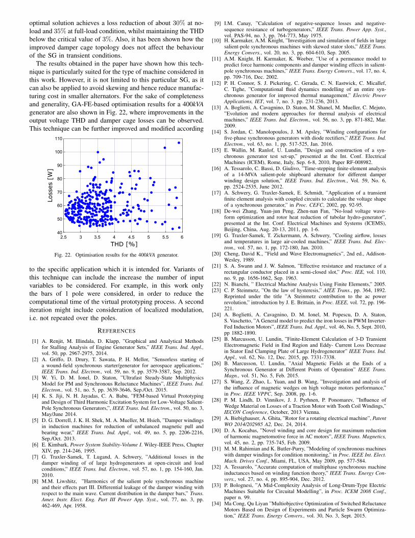
The results obtained in the paper have shown how this tech-nique is particularly suited for the type of machine considered inthis work. However, it is not limited to this particular SG, as itcan also be applied to avoid skewing and hence reduce manufac-turing cost in smaller alternators. For the sake of completenessand generality, GA-FE-based optimisation results for a 400kVAgenerator are also shown in Fig. 22, where improvements in theoutput voltage THD and damper cage losses can be observed.This technique can be further improved and modified according
2.5 3 3.5 4 4.5 5 5.5 640
50
60
70
80
90
100
110
THD [%]
Loss
es [
W]
Fig. 22. Optimisation results for the 400kVA generator.
to the specific application which it is intended for. Variants ofthis technique can include the increase the number of inputvariables to be considered. For example, in this work onlythe bars of 1 pole were considered, in order to reduce thecomputational time of the virtual prototyping process. A seconditeration might include consideration of localized modulation,i.e. not repeated over the poles.
REFERENCES
[1] A. Renjit, M. Illindala, D. Klapp, ”Graphical and Analytical Methodsfor Stalling Analysis of Engine Generator Sets,” IEEE Trans. Ind. Appl.,vol. 50, pp. 2967-2975, 2014.
[2] A. Griffo, D. Drury, T. Sawata, P. H. Mellor, ”Sensorless starting ofa wound-field synchronous starter/generator for aerospace applications,”IEEE Trans. Ind. Electron., vol. 59, no. 9, pp. 3579-3587, Sep. 2012.
[3] W. Yi, D. M. Ionel, D. Staton, ”Ultrafast Steady-State MultiphysicsModel for PM and Synchronous Reluctance Machines”, IEEE Trans. Ind.Electron., vol. 51, no. 5, pp. 3639-3646, Sep./Oct. 2015.
[4] K. S. Jiji, N. H. Jayadas, C. A. Babu, ”FEM-based Virtual Prototypingand Design of Third Harmonic Excitation System for Low-Voltage Salient-Pole Synchronous Generators,”, IEEE Trans. Ind. Electron., vol. 50, no. 3,May/June 2014.
[5] D. G. Dorrell, J. K. H. Shek, M. A. Mueller, M. Hsieh, ”Damper windingsin induction machines for reduction of unbalanced magnetic pull andbearing wear,” IEEE Trans. Ind. Appl., vol. 49, no. 5, pp. 2206-2216,Sep./Oct. 2013.
[6] E. Kimbark, Power System Stability-Volume I. Wiley-IEEE Press, ChapterXIV, pp. 214-246, 1995.
[7] G. Traxler-Samek, T. Lugand, A. Schwery, ”Additional losses in thedamper winding of of large hydrogenerators at open-circuit and loadconditions,” IEEE Trans. Ind. Electron., vol. 57, no. 1, pp. 154-160, Jan.2010.
[8] M.M. Liwshitz, ”Harmonics of the salient pole synchronous machineand their effects part III. Differential leakage of the damper winding withrespect to the main wave. Current distribution in the damper bars,” Trans.Amer. Instr. Elect. Eng. Part III Power App. Syst., vol. 77, no. 3, pp.462-469, Apr. 1958.
[9] I.M. Canay, ”Calculation of negative-sequence losses and negative-sequence resistance of turbogenerators,” IEEE Trans. Power App. Syst.,vol. PAS-94, no. 3, pp. 764-773, May 1975.
[10] H. Karmaker, A.M. Knight, ”Investigation and simulation of fields in largesalient-pole synchronous machines with skewed stator slots,” IEEE Trans.Energy Convers., vol. 20, no. 3, pp. 604-610, Sep. 2005.
[11] A.M. Knight, H. Karmaker, K. Weeber, ”Use of a permeance model topredict force harmonic components and damper winding effects in salient-pole synchronous machines,” IEEE Trans. Energy Convers., vol. 17, no. 4,pp. 709-716, Dec. 2002.
[12] P. H. Connor, S. J. Pickering, C. Gerada, C. N. Eastwick, C. Micallef,C. Tighe, ”Computational fluid dynamics modelling of an entire syn-chronous generator for improved thermal management,” Electric PowerApplications, IET, vol. 7, no. 3. pp. 231-236, 2013.
[13] A. Boglietti, A. Cavagnino, D. Staton, M. Shanel, M. Mueller, C. Mejuto,”Evolution and modern approaches for thermal analysis of electricalmachines,” IEEE Trans. Ind. Electron., vol. 56, no. 3, pp. 871-882, Mar.2009.
[14] S. Jordan, C. Manolopoulos, J. M. Apsley, ”Winding configurations forfive-phase synchronous generators with diode rectifiers,” IEEE Trans. Ind.Electron., vol. 63, no. 1, pp. 517-525, Jan. 2016.
[15] E. Wallin, M. Ranlof, U. Lundin, ”Design and construction of a syn-chronous generator test set-up,” presented at the Int. Conf. ElectricalMachines (ICEM), Rome, Italy, Sep. 6-8, 2010, Paper RF-008982.
[16] A. Tessarolo, C. Bassi, D. Giulivo, ”Time-stepping finite-element analysisof a 14-MVA salient-pole shipboard alternator for different damperwinding design solution,” IEEE Trans. Ind. Electron., Vol. 59, No. 6,pp. 2524-2535, June 2012.
[17] A. Schwery, G. Traxler-Samek, E. Schmidt, ”Application of a transientfinite element analysis with coupled circuits to calculate the voltage shapeof a synchronous generator,” in Proc. CEFC, 2002, pp. 92-95.
[18] De-wei Zhang, Yuan-jun Peng, Zhen-nan Fan, ”No-load voltage wave-form optimization and rotor heat reduction of tubolar hydro-generator”,presented at the Int. Conf. Electrical Machines and Systems (ICEMS),Beijing, China, Aug. 20-13, 2011, pp. 1-6.
[19] G. Traxler-Samek, T. Zickermann, A. Schwery, ”Cooling airflow, lossesand temperatures in large air-cooled machines,” IEEE Trans. Ind. Elec-tron., vol. 57, no. 1, pp. 172-180, Jan. 2010.
[20] Cheng, David K., ”Field and Wave Electromagnetics”, 2nd ed., Addison-Wesley, 1989.
[21] S. A. Swann and J. W. Salmon, ”Effective resistance and reactance of arectangular conductor placed in a semi-closed slot,” Proc. IEE, vol. 110,no. 9, pp. 1656-1662, Sep. 1963.
[22] N. Bianchi, ” Electrical Machine Analysis Using Finite Elements,” 2005.[23] C. P. Steinmetz, ”On the law of hysteresis,” AIEE Trans., pp. 364, 1892.
Reprinted under the title ”A Steinmetz contribution to the ac powerrevolution,” introduction by J. E. Brittain, in Proc. IEEE, vol. 72, pp. 196-221.
[24] A. Boglietti, A. Cavagnino, D. M. Ionel, M. Popescu, D. A. Staton,S. Vaschetto, ”A General model to predict the iron losses in PWM Inverter-Fed Induction Motors”, IEEE Trans. Ind. Appl., vol. 46, No. 5, Sept. 2010,pp 1882-1890.
[25] B. Marcusson, U. Lundin, ”Finite-Element Calculation of 3-D TransientElectromagnetic Field in End Region and Eddy- Current Loss Decreasein Stator End Clamping Plate of Large Hydrogenerator” IEEE Trans. Ind.Appl., vol. 62, No. 12, Dec. 2015, pp. 7331-7338.
[26] B. Marcusson, U. Lundin, ”Axial Magnetic Fields at the Ends of aSynchronous Generator at Different Points of Operation” IEEE Trans.Magn., vol. 51, No. 5, Feb. 2015.
[27] S. Wang, Z. Zhao, L. Yuan, and B. Wang, ”Investigation and analysis ofthe influence of magnetic wedges on high voltage motors performance,”in Proc. IEEE VPPC, Sep. 2008, pp. 1-6.
[28] P. M. Lindh, D. Vinnikov, J. J. Pyrhnen, P. Ponomarev, ”Influence ofWedge Material on Losses of a Traction Motor with Tooth Coil Windings,”IECON Conference, October, 2013 Vienna.
[29] A. Biebighauser, A. Ghita, ”Rotor for a rotating electrical machine”, PatentWO 2014/202985 A2, Dec. 24, 2014.
[30] D. A. Kocabas, ”Novel winding and core design for maximum reductionof harmonic magnetomotive force in AC motors”, IEEE Trans. Magnetics,vol. 45, no. 2, pp. 735-745, Feb. 2009.
[31] M. M. Rahimian and K. Butler-Purry, ”Modeling of synchronous machineswith damper windings for condition monitoring,” in Proc. IEEE Int. Elect.Mach. Drives Conf., Miami, FL, USA, May 2009, pp. 577-584.
[32] A. Tessarolo, ”Accurate computation of multiphase synchronous machineinductances based on winding function theory,” IEEE Trans. Energy Con-vers., vol. 27, no. 4, pp. 895-904, Dec. 2012.
[33] P. Bolognesi, ”A Mid-Complexity Analysis of Long-Drum-Type ElectricMachines Suitable for Circuital Modelling”, in Proc. ICEM 2008 Conf.,paper n. 99.
[34] Ma Cong, Qu Liyan ”Multiobjective Optimization of Switched ReluctanceMotors Based on Design of Experiments and Particle Swarm Optimiza-tion,” IEEE Trans. Energy Convers., vol. 30, No. 3, Sept. 2015.

[35] M. A. Khan, I. Husain, M. R. Islam, J. T. Klass, ”Design of experimentsto address manufacturing tolerances and process variations influencingcogging torque and back EMF in the mass production of the permanent-magnet synchronous motors,” IEEE Trans. Ind. Appl., vol. 50, no. 1, pp.346-355, Jan./Feb. 2014.
[36] Poles S., Technical Report 2003-006, ”MOGA-II An improved Multi-Objective Genetic Algorithm.”
[37] IEEE 115, Guide for Test Procedures for Synchronous Machines PartI - Acceptance and Performance Testing Part II-Test Procedures andParameter Determination for Dynamic Analysis, 2009.


![z, [5]...(b) Draw the phasor diagram of an over-excited non-salient pole synchronous motor having per phase z,=ra +jxs. [5] (c) Draw the phasor diagram of salient pole over excited](https://static.fdocuments.us/doc/165x107/609339e08132dc4c4d4cea7e/z-5-b-draw-the-phasor-diagram-of-an-over-excited-non-salient-pole-synchronous.jpg)