Improved Cleaner CIrCuIt performanCe at the … LIT... · J. Knoblauch1 - principle metallurgist H...
9
IMPROVED CLEANER CIRCUIT PERFORMANCE AT THE DEGRUSSA COPPER MINE WITH AN IN SITU COLUMN SPARGING SYSTEM J. Knoblauch 1 - Principle Metallurgist H. Thanasekaran 2 - Senior Process Engineer E. Wasmund 3 - Global Managing Director 1 More information is available at www.eriezflotation.com ABSTRACT Sandfire’s DeGrussa Copper-Gold operation in West Australia is a new high grade copper sulfide mine, which includes a 1.5 Mtpa concentrator which was completed in 2013. Early after commissioning, it was identified that the flotation capacity in the all-mechanical cleaner circuit was not sufficient. In order to improve recovery, the tail from the cleaner scavenger was sent back to feed the rougher scavengers. Test-work was done on-site to evaluate the possibility of using a flotation column as a pre-cleaner. A CavTube™ sparging system was selected, which is especially effective for fine ore particle flotation. Test-work was conducted at site using a 150 mm diameter unit, and then confirmed on a 500 mm diameter unit. A 4250 mm diameter full scale unit was installed in Q4 2014 and commissioned in Q1 2015. This unit gave some significant advantages including a reduction in re-grinding requirements, elimination of a circulating load and increase in the recovery of copper in the cleaner circuit and overall circuit. In this presentation, the benefits of columns and cavitation sparging for floating fine particles and rejecting fine entrained gangue will be explained. Also, the results from a lab unit and a pilot unit will be compared against the results of the full-scale unit. The paper will demonstrate the scalability of flotation columns, and which phenomena and scale-up criteria must be considered to be successful. Finally, some general observations will be made about the importance of columns in copper cleaning circuits. KEYWORDS Flotation, Copper Cleaner Circuit, CavTube Sparger, Fine Particle Flotation, Column Flotation Cell INTRODUCTION Sandfire Resources’ DeGrussa copper-gold concentrator is located approximately 900 km north-north-east of Perth in Western Australia. The project area landscape is scrubby mulga lands with few notable features. The climate is arid with high temperature and heavy summer downpours. The ore body was discovered on Tuesday 28 April, 2009 by John Evans, Sandfire’s chief technical director. The DeGrussa ore body comprises lateritic gold, oxide copper and supergene copper which is vertically above hypogene mineralization. On the Hypogene mineralization more than 90 per cent is massive sulfide, which mainly consists of pyrite, chalcopyrite, pyrrhotite, sphalerite and subordinate galena, as well as minnesotaite (talc) and magnetite. 1 More information is available at www.eriezflotation.com 1. Sandfire Resources NL Level 1, 31 Ventnor Avenue, West Perth, WA-6872, Australia 2. Eriez Flotation Division Australia 21 Shirley Way, Epping, Victoria 3076, Australia 3. Eriez Flotation Division Canada 7168 Venture Street, Delta, BC, Canada, V4G 1H6
Transcript of Improved Cleaner CIrCuIt performanCe at the … LIT... · J. Knoblauch1 - principle metallurgist H...

Improved Cleaner CIrCuIt performanCe at the degrussa Copper mIne wIth an In sItu Column spargIng systemJ. Knoblauch1 - principle metallurgistH. Thanasekaran2 - senior process engineerE. Wasmund3 - global managing director
1More information is available at www.eriezflotation.com
abstraCtsandfire’s degrussa Copper-gold operation in west australia is a new high grade copper sulfide mine, which includes a 1.5 mtpa concentrator which was completed in 2013.
early after commissioning, it was identified that the flotation capacity in the all-mechanical cleaner circuit was not sufficient. In order to improve recovery, the tail from the cleaner scavenger was sent back to feed the rougher scavengers. test-work was done on-site to evaluate the possibility of using a flotation column as a pre-cleaner. a Cavtube™ sparging system was selected, which is especially effective for fine ore particle flotation. test-work was conducted at site using a 150 mm diameter unit, and then confirmed on a 500 mm diameter unit. a 4250 mm diameter full scale unit was installed in Q4 2014 and commissioned in Q1 2015. this unit gave some significant advantages including a reduction in re-grinding requirements, elimination of a circulating load and increase in the recovery of copper in the cleaner circuit and overall circuit.
In this presentation, the benefits of columns and cavitation sparging for floating fine particles and rejecting fine entrained gangue will be explained. also, the results from a lab unit and a pilot unit will be compared against the results of the full-scale unit. the paper will demonstrate the scalability of flotation columns, and which phenomena and scale-up criteria must be considered to be successful. finally, some general observations will be made about the importance of columns in copper cleaning circuits.
Keywordsflotation, Copper Cleaner Circuit, Cavtube sparger, fine particle flotation, Column flotation Cell
IntroduCtIonsandfire resources’ degrussa copper-gold concentrator is located approximately 900 km north-north-east of perth in western australia. the project area landscape is scrubby mulga lands with few notable features. the climate is arid with high temperature and heavy summer downpours.
the ore body was discovered on tuesday 28 april, 2009 by John evans, sandfire’s chief technical director. the degrussa ore body comprises lateritic gold, oxide copper and supergene copper which is vertically above hypogene mineralization. on the hypogene mineralization more than 90 per cent is massive sulfide, which mainly consists of pyrite, chalcopyrite, pyrrhotite, sphalerite and subordinate galena, as well as minnesotaite (talc) and magnetite.
1more information is available at www.eriezflotation.com
1. Sandfire Resources NL level 1, 31 ventnor avenue, west perth, wa-6872, australia
2. Eriez Flotation Division Australia 21 shirley way, epping, victoria 3076, australia
3. Eriez Flotation Division Canada 7168 venture street, delta, bC, Canada, v4g 1h6

2More information is available at www.eriezflotation.com
degrussa commenced as an open-pit operation but now treats solely underground ore through its 1.5 mtpa concentrator. the concentrator plant was built in 2011 and commenced commercial production in september 2012. now degrussa is firmly established as one of the asia-pacific region’s premier, high-grade copper mine. the concentrator produces up to 300,000 tonnes-a-year of high grade copper concentrate.
proCessIng plant desCrIptIona simplified flow sheet of the degrussa concentrator, from 2014 is shown as figure 1. the concentrator feed is blended from four different zones of massive sulphide mineralization: degrussa, Conductor 1, Conductor 4 and Conductor 5. this blend is determined by availability, composition and production targets.
ore is processed through a conventional flotation circuit to separate the valuable copper sulphide bearing particles. the details of the flotation cells are listed in table 1.
the rougher/scavenger flotation circuit consistently recovers 91% of the total copper sulphide minerals, with the greatest loss typically being from the >75µm and <7µm size fraction. the enrichment ratio on the rougher/scavenger flotation stage is around 4.5 to 5.0. the tailing from the rougher/scavenger flotation circuit is sent to the final tailing hopper.
Concentrate from the rougher/scavenger circuit is fed via a cluster of hydro cyclones to a regrind circuit. underflow from the cyclones reports to an Isamill where it is reduced in size to approximately 80% passing 18 µm. the product from the Isamill is combined with the regrind cyclone overflow before being fed to the cleaner circuit. the cleaner circuit operates with the following recirculating loads:
• recleaner tailing to first cleaner
• Cleaner scavenger concentrate to regrind mill
• Cleaner scavenger tailing to scavenger cells
FIGURE 1degrussa copper mine processing
flow sheet, 2014
# of Cells Function Model Capacity
(m3)2 rougher tK-50 50
6 scavenger tK-50 50
6 first Cleaner tK-30 30
4 Cleaner scavenger tK-30 30
6 recleaner oK-16-u 16
TABLE 1degrussa processing plant flotation equipment

3More information is available at www.eriezflotation.com
the final tailings of the cleaner circuit are returned to the head of the scavenger circuit. the recycle provides an opportunity to recover valuable copper sulphide minerals in the cleaner tailings with additional retention time in the flotation circuit and/or to handle upsets in the cleaner circuit. the initial design target in the cleaning stage recovery was 90 per cent.
InItIal flotatIon CIrCuIt performanCeIn 2013, plant commissioning was progressed with the ore throughput and production on track to achieve demonstrated nameplate levels of 125,000 tonnes per month by mid-2013. under normal operating conditions, the rougher flotation stage recovers 50 to 60 per cent of the copper in the feed and the scavenger flotation stage varies from time to time. the total recovery in the rougher/scavenger circuit remains relatively consistent.
based on the plant monthly data, the average copper recovery in the cleaner circuit was generally between 75 to 82 per cent. during april 2014 when the average mill throughput was 125,000 tonnes per month with an average feed grade of 4.8 per cent copper, the plant copper recovery was 89.1 per cent. during this peak production period, a detailed plant survey was conducted. the recoveries in the rougher, scavenger and cleaner circuits based on individual circuit feed were 65 per cent, 80 per cent and 81 per cent. the significantly lower cleaner flotation circuit recovery implies that the cleaner circuit was heavily overloaded.
when the cleaner circuit is overloaded, recycle of the cleaner tailings results in floatable valuable minerals building up in the scavenger circuits. If the condition lasts significantly longer than the circuit residence time, the rougher and scavenger circuits will eventually reach their capacity limit and recovery will start to decrease. the overall plant recovery becomes dependent on recovery in the cleaner circuit during high mill throughput and feed grade periods.
the plant historical copper concentrate grade data showed that a large portion of liberated, non-sulfide non- floating gangue material was being recovered to the copper concentrate via entrainment. particle size and mineralogical data for January 2014 were collected from the plant and reported by als, (als Quantitative automated mineralogical analysis march, 2014). this snap-shot data is representative of the character of the operation for that period of time. the flotation plant feed had a grade of approximately 5.04 per cent copper with p80 of 40 µm. Chalcopyrite was the only significant copper bearing mineral, and the feed contained 31.9 per cent pyrite, 14.2 per cent chalcopyrite, 9.4 per cent pyrrhotite, and 2.2 per cent sphalerite and lesser quantities of other sulfides. 76.3 per cent of the chalcopyrite in the float feed was fully liberated.
the plant final concentrate copper had a grade of 25.5 per cent copper with p80 of 24 µm. the major diluents in the final concentrate grade were iron sulphide (predominately pyrite, with trace of pyrrhotite). as shown in figure 2, 38.5 per cent of the pyrite in the final concentrate stream was liberated and these were distributed predominately in the fines and ultra-fines.
FIGURE 2pyrite liberation in float feed (ff), recleaner
concentrate (rCC), cleaner scavenger tail (Cst), scavenger tail (st), flash cleaner
concentrate (fCC)
FIGURE 3non sulphide gangue liberation in float feed (ff),
recleaner concentrate (rCC), cleaner scavenger tail (Cst), scavenger tail (st), flash cleaner
concentrate (fCC)

4More information is available at www.eriezflotation.com
other diluents included phyllosilicates and other non-sulphide gangue which accounted for 4.4 per cent of this stream and were distributed across all liberation classes. also 37 per cent of the non-sulphide gangue in the final concentrate stream was fully liberated which is shown in figure 3. Considering the high amount of ultra-fines in the cleaner circuit, it was confirmed that the existing conventional cells are recovering a significant portion of liberated non-sulphide gangue to the final concentrate stream through entrainment.
Cleaner CIrCuIt optmIsatIonbased on the eighteen months of operational and plant survey data, sandfire decided to install additional flotation cells in the cleaner circuit to improve recovery and concentrate grade. the choice of flotation column over mechanical cells was based on four main considerations. Column flotation offers improved recovery over conventional cells due to their ability to simultaneously provide high superficial bubble area and collision rates, relatively plug flow conditions, and a low-turbulence environment. most importantly, columns allow for higher grades given deep froths that can be effectively washed. Column cells provide more flexibility with air-rate, froth depth and wash water addition adjustments. additional benefits include a smaller foot print and savings in steel work and concrete.
theory of In sItu spargIng (Cavtube spargIng system)It is well known that recovery by flotation is strongly dependent on particle size, as well as other considerations such as liberation, bubble size, density and hydrodynamics. figure 4 (bulatovic, 2007) shows typical copper flotation performance by particle size for major operations that are using mainly conventional mechanical cells. this graph shows a passband between 50 and 150-200 microns where conventional flotation gives good performance. as the size is decreased below 50 microns or above 200 microns, the recovery attenuates rapidly.
an explanation for lower recoveries of fine liberated particles has been proposed by sutherland (1948), who described the flotation recovery rate process mathematically as the product of the probability of collision, the probability of attachment and the inverse of the probability of detachment. the probability of collision is often written as being proportional to the second power of the ratio of the particle size to the bubble size. In other words fine particles are not effectively collected by large bubbles. the physical explanation for this is that smaller particles have lower inertia and are more likely to remain in the fluid streamlines that travel around the bubble’s boundary layer, than to diverge from the streamline and intercept the bubble. larger particles, relative to bubble size, are less likely to track the fluid streamlines and will successfully collide with the bubble when they come in close proximity.
FIGURE 4Copper recovery at various size fractions (%)
5More information is available at www.eriezflotation.com
In-situ sparging systems such as eriez’ Cavtube™ sparger, introduce fine bubbles and bubbles that will form and grow on hydrophobic surfaces. In this device, ore slurry is typically mixed with pressurized air pumped through a sudden contraction and expansion. as the compressed feed is expanded, bubbles on the order of 100 microns in size are formed by shearing apart large gas slugs. additionally, as the local pressure exerted on the slurry drops, the concentration of dissolved gases like nitrogen and oxygen become supersaturated and can nucleate as fine bubbles of the order of 1 micron in size. If the local pressure of the liquid drops below the vapor pressure, the liquid will also become supersaturated with respect to water vapor, resulting in cavitation. as with other super-saturation phenomenon, nucleation onto existing surfaces (heterogeneous nucleation), especially hydrophobic surfaces, will take place preferentially over homogeneous nucleation, due to the additional energy required to create a new interface. so when ore slurry is pumped through an array of Cavtubes, it is possible to create a bimodal bubble size distribution with two main modes at about 1-2 microns and 100-200 microns respectively. many of the fine bubbles, which only make up on the order of 2% of the total bubble volume, will be mostly tethered to the ore particles because of the preponderance of heterogeneous nucleation as shown by fan (fan et al, 2010a, fan et al, 2010b). a recent study (Krasowska and malysa, 2007) using a model system showed that large bubbles had a higher sticking efficiency when impinging against solid surfaces that had pre-existing adsorbed fine bubbles. therefore, there is good evidence to support the idea that a combination of large and small bubbles produced by the Cavtube is especially effective for the attachment of bubbles onto fine ore particles.
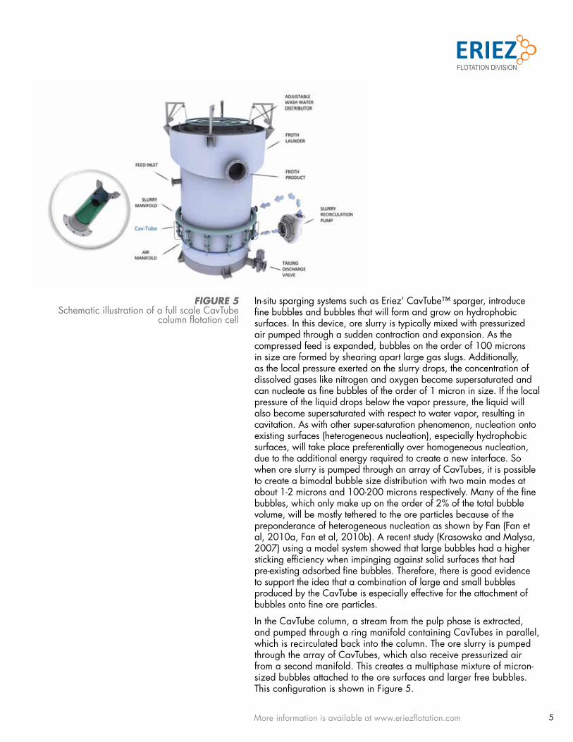
In the Cavtube column, a stream from the pulp phase is extracted, and pumped through a ring manifold containing Cavtubes in parallel, which is recirculated back into the column. the ore slurry is pumped through the array of Cavtubes, which also receive pressurized air from a second manifold. this creates a multiphase mixture of micron-sized bubbles attached to the ore surfaces and larger free bubbles. this configuration is shown in figure 5.
FIGURE 5schematic illustration of a full scale Cavtube
column flotation cell

6More information is available at www.eriezflotation.com
pIlot test-worK, sCale-up and InstallatIonto identify whether the addition of columns could make an improvement to the cleaning circuit, a number of candidate locations were evaluated on-site using a “lab-scale” 150 mm (3 inch) diameter test column. on-site test-work, if available, is the best way to evaluate the metallurgical performance of a flotation column. the main scale-up parameters are residence time and carrying capacity. In other words, the amount of time the pulp spends in the column and the rate of froth being recovered over a fixed cross-sectional area. these results can be checked against eriez’ in-house database developed from hundreds of applications, to confirm that the test-work is representative. the eriez flotation division technical team worked with the experts at sandfire for more than four months to identify the best location for a column in the existing flow sheet to produce optimal results for degrussa. this initial lab-scale survey indicated that good results would be obtained by installing a column at the head of the existing cleaner circuit, as a cleaner scalper. these results were subsequently validated on a 500 mm (20 inch) diameter pilot plant unit which reduced the amount of risk for sandfire to go ahead with a full-scale 4.27 meter diameter by 10.0 meter high unit. photographs of the 500 mm pilot unit and the 4.27 meter full-scale unit are shown as figure 6.
In 2014, sandfire allocated approximately $14 million towards processing plant enhancements at degrussa and the copper cleaner column was part of that package. the column was subsequently installed in december 2014 and commissioned in february 2015. the modified flow sheet is shown as figure 7.
FIGURE 6photograph showing the installation of the
industrial column flotation cell and 500mm pilot column unit
FIGURE 7flotation circuit configuration after cleaner circuit upgrade

7More information is available at www.eriezflotation.com
Improvement In plant performanCea comparison of the grade-recovery curve for each of the three sizes of column cells in this study is shown in figure 8. the metallurgical performance for a scale-up of diameter approximately 30 times is roughly on the same grade-recovery curve, which provides confidence that the scale-up criteria for columns is well known and the results can be predictable.
as a result of this single new column, the degrussa operations were able to achieve some considerable benefits. the main benefit of the Cavtube column was derived from rejection of non-sulfide gangue allowing the recovery of valuable composite particles as well as liberated fines. secondly, the rougher concentrate stream could be sent directly to the column cell (compare figure 1 and figure 7), thereby minimizing the load on the regrind mill and allowing higher kinetics on the cleaner circuit. finally, the circulating load between the cleaner scavenger tail and the scavenger feed, was no longer required so that the cleaner scavenger tail could go to final tails.
prior to installation of the column, froth in the existing conventional cleaner cells was tenacious and stable, with poor mobility and heavily loaded. as a result, entrainment of non sulphide gangue was very high due to the poor froth drainage and lack of wash water. In effect the cleaner circuit had to be run less aggressively to increase the copper grade which also resulted in lower copper recoveries. the operators must choose between recovery and grade. more often operators had to split the cleaner and recleaner feed into multiple cells to minimize the loading on the cells. the cleaner feed stream was split into three streams and fed into cell 1, 3 & 5. there was also a similar configuration on the recleaner cells. since the column commissioning the issue was resolved as there is now much less floatable material reporting to the mechanical cells. unlike conventional cells, column flotation technology allows for froth washing which improves froth mobility, decreases entrainment and maximizes grade.
FIGURE 8test results of full-scale industrial column
and pilot test unit.
8More information is available at www.eriezflotation.com
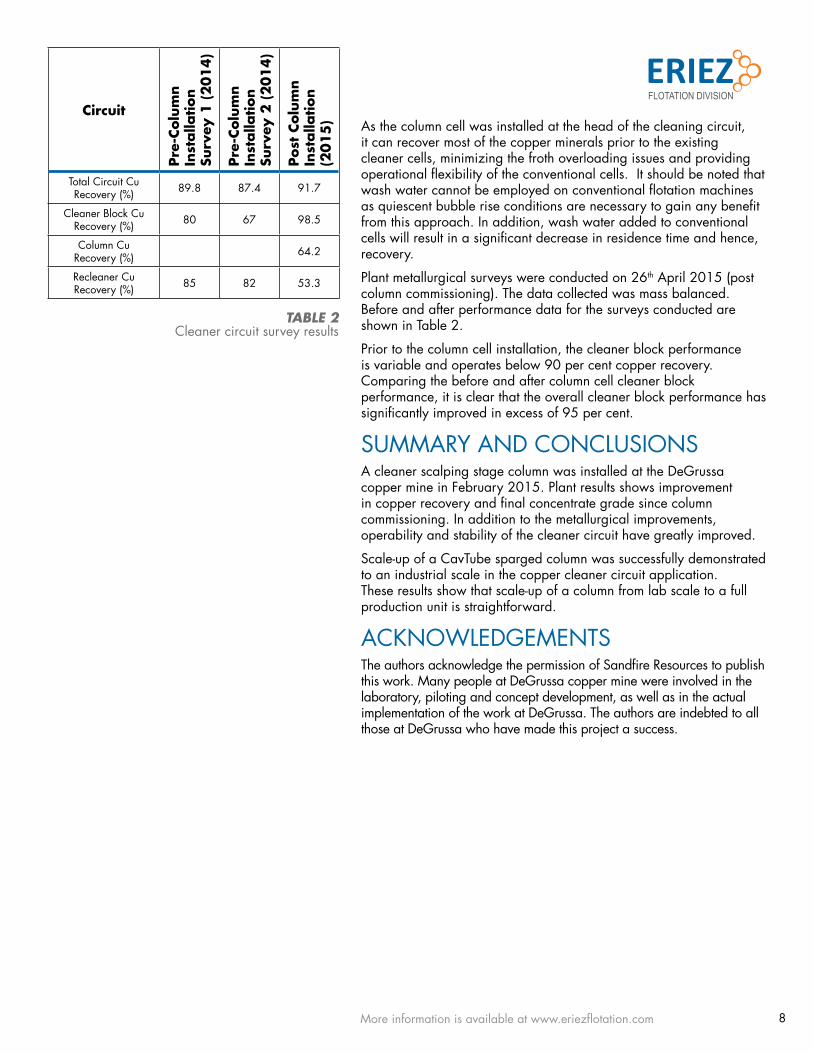
as the column cell was installed at the head of the cleaning circuit, it can recover most of the copper minerals prior to the existing cleaner cells, minimizing the froth overloading issues and providing operational flexibility of the conventional cells. It should be noted that wash water cannot be employed on conventional flotation machines as quiescent bubble rise conditions are necessary to gain any benefit from this approach. In addition, wash water added to conventional cells will result in a significant decrease in residence time and hence, recovery.
plant metallurgical surveys were conducted on 26th april 2015 (post column commissioning). the data collected was mass balanced. before and after performance data for the surveys conducted are shown in table 2.
prior to the column cell installation, the cleaner block performance is variable and operates below 90 per cent copper recovery. Comparing the before and after column cell cleaner block performance, it is clear that the overall cleaner block performance has significantly improved in excess of 95 per cent.
summary and ConClusIonsa cleaner scalping stage column was installed at the degrussa copper mine in february 2015. plant results shows improvement in copper recovery and final concentrate grade since column commissioning. In addition to the metallurgical improvements, operability and stability of the cleaner circuit have greatly improved.
scale-up of a Cavtube sparged column was successfully demonstrated to an industrial scale in the copper cleaner circuit application. these results show that scale-up of a column from lab scale to a full production unit is straightforward.
aCKnowledgementsthe authors acknowledge the permission of sandfire resources to publish this work. many people at degrussa copper mine were involved in the laboratory, piloting and concept development, as well as in the actual implementation of the work at degrussa. the authors are indebted to all those at degrussa who have made this project a success.
Circuit
Pre-
Colu
mn
Inst
alla
tion
Surv
ey 1
(2014)
Pre-
Colu
mn
Inst
alla
tion
Surv
ey 2
(2014)
Post
Col
umn
Inst
alla
tion
(2015
)
total Circuit Cu recovery (%) 89.8 87.4 91.7
Cleaner block Cu recovery (%) 80 67 98.5
Column Cu recovery (%) 64.2
recleaner Cu recovery (%) 85 82 53.3
TABLE 2Cleaner circuit survey results
9More information is available at www.eriezflotation.com
Eriez flotation division | Canada Inc7168 venture stdelta, bC, v4g 1h6Canadaoffice: +1 [email protected]
referenCes1. als Quantitative automated mineralogical analysis on monthly
plant Composites from degrussa mar 2014 (2014).
2. bulatovic, s. m., (2007). handbook of flotation reagents: chemistry, theory and practice: volume 1: flotation of sulfide ores. elsevier.
3. sutherland K.l., (1948). “physical chemistry of flotation. XI. Kinetics of the flotation process”, J. phys. Chem., vol 52, pp 394-425.
4. fan, m.m. et al, (2010). “nanobubble generation and its application in froth flotation (part I): nanobubble generation and its effects on properties of microbubble and millimeter scale bubble solutions”, mining sci. & tech, 20, pp 1-19.
5. fan, m.m. et al, (2010). “nanobubble generation and its applications in froth flotation (part II): fundamental study and theoretical analysis”, mining sci. & tech, 20, pp 159-177.
6. Krasowska, m., malysa, K., (2007). “Kinetics of bubble collision and attachment to hydrophobic solids: 1. effect of surface roughness, Int. Journal of mineral processing, 81, pp 205-216
316-web-aha
this paper was originally published at the Canadian mineral processors national Conference, ottawa, Canada, Jan 20, 2016