IMPROVED 3D CITY MODELING WITH CYBERCITY-MODELER (CC … · IMPROVED 3D CITY MODELING WITH...
6
International Archives of the Photogrammetry, Remote Sensing and Spatial Information Sciences, Vol. XXXIV-5/W10 IMPROVED 3D CITY MODELING WITH CYBERCITY-MODELER (CC-MODELER™) USING AERIAL-, SATELLITE IMAGERY AND LASERSCANNER DATA Kilian Ulm CyberCity AG, c/o Chair of Photogrammetry ETH Zurich Hoenggerberg, CH-8093 Zurich Switzerland, [email protected] KEY WORDS: 3D city modeling, photogrammetry, satellite imagery, laserscanner data, real-time visualisation ABSTRACT: Semi-automated object extraction has been established as a standard procedure for the efficient generation of 3D city models. Apart from aerial imagery, satellite imagery and laserscanner data turned out to be an additional source to create virtual city models. CyberCity-Modeler (CC-Modeler™) as a tool for the generation and optimisation of 3D city and plant models has been used in a range of projects with different requirements. Therefore modules have been developed and integrated to the main software package to improve functionality. CC-Modeler™ consists of four modules: CC-Modeler for topological structuring, CC-Edit for improving geometry , CC-Mapping for integration of wall texture and CC-Digit for integration of digitised data from maps. Concerning the software package CC-Modeler™, some functions as geometrical regularisation of buildings, editing functions for topology adjustment, modeling of overhanging roofs, adding attributes to objects, mapping from texture libraries, generation of corridors etc. are explained in this paper. Additionally, the use of satellite and laserscanner data for the efficient generation of 3D city models as an alternative or supplement to aerial images is discussed and the progress in real-time visualisation of 3D city models is presented. 1 INTRODUCTION CyberCity-Modeler (CC-Modeler™) uses semi-automated object extraction from stereo-models of aerial and satellite imagery towards the generation of realistic 3D building models. Additionally, all objects which can be represented as polyhedral models like digital terrain models (DTM), roads, waterways, trees etc. can be modeled. The automatic detection of main roof types from laserscanner data is under development. CC-Modeler™ is a commercial software product that is marketed by the ETH Zurich spin-off company CyberCity AG. Realistic 3D city models are used primarily in city-, facility planning but also in location planning of telecom companies, 3D car navigation systems, scene modeling in game industry etc. Due to variability of applications, the software is improved ongoing with the different project specifications and is adapted to specific needs and requirements. This paper discusses data capturing of point clouds from a stereo-model for further processing with CC-Modeler™. In addition, the four modules of the CC-Modeler™ are presented and the workflow to improve the 3D building model is pointed out. Furthermore, functions like generation of overhanging roofs, adding basements and attributes are explained. Results (incl. accuracy) from different data sources like aerial and satellite imagery and laserscanner data are discussed. Eventually, latest progress in real-time visualisation of 3D city models is presented. 2 DATA CAPTURING FOR 3D CITY MODELING WITH CC-MODELER™ Photogrammetry assists in derivation of information on surface cover (e.g. vegetation) and man-made objects (e.g. buildings, roads, bridges etc.). CC-Modeler™ enables generation of 3D building models from aerial images with use of a semi- automated method. This topology generator fits planar structures to point clouds that are measured by a human operator. The photogrammetric measurement and structuring is done on Analytical Plotters or on Digital Photogrammetric Workstations (e.g. Virtuozo, Socet Set, Z/I Image-station etc.). The operator classifies the captured points in boundary points and interior points, based on their different functionality in one object (Figure 1). Different codes are assigned to these points, which help the CC-Modeler to generate the roof faces and an accurate topology. Each roof type can be generated and there are no constraints regarding a roof type library. Figure 1. Point definition in CC-Modeler. The points of the roof boundary polygon have to be measured clockwise or counter-clockwise (in case of the interior points, no sequence has to be kept). The interpretation of the data depends on the operator which gives the opportunity to achieve any level of detail. With this method, hundreds of objects (i.e. buildings, roads, bridges etc.) can be measured by one operator in one day.
Transcript of IMPROVED 3D CITY MODELING WITH CYBERCITY-MODELER (CC … · IMPROVED 3D CITY MODELING WITH...

International Archives of the Photogrammetry, Remote Sensing and Spatial Information Sciences, Vol. XXXIV-5/W10
IMPROVED 3D CITY MODELING WITH CYBERCITY-MODELER (CC-MODELER™)USING AERIAL-, SATELLITE IMAGERY AND LASERSCANNER DATA
Kilian Ulm
CyberCity AG, c/o Chair of PhotogrammetryETH Zurich Hoenggerberg, CH-8093 Zurich
Switzerland, [email protected]
KEY WORDS: 3D city modeling, photogrammetry, satellite imagery, laserscanner data, real-time visualisation
ABSTRACT:
Semi-automated object extraction has been established as a standard procedure for the efficient generation of 3D city models. Apartfrom aerial imagery, satellite imagery and laserscanner data turned out to be an additional source to create virtual city models.CyberCity-Modeler (CC-Modeler™) as a tool for the generation and optimisation of 3D city and plant models has been used in arange of projects with different requirements. Therefore modules have been developed and integrated to the main software packageto improve functionality. CC-Modeler™ consists of four modules: CC-Modeler for topological structuring, CC-Edit for improvinggeometry , CC-Mapping for integration of wall texture and CC-Digit for integration of digitised data from maps. Concerning thesoftware package CC-Modeler™, some functions as geometrical regularisation of buildings, editing functions for topologyadjustment, modeling of overhanging roofs, adding attributes to objects, mapping from texture libraries, generation of corridors etc.are explained in this paper. Additionally, the use of satellite and laserscanner data for the efficient generation of 3D city models as analternative or supplement to aerial images is discussed and the progress in real-time visualisation of 3D city models is presented.
1 INTRODUCTION
CyberCity-Modeler (CC-Modeler™) uses semi-automatedobject extraction from stereo-models of aerial and satelliteimagery towards the generation of realistic 3D building models.Additionally, all objects which can be represented as polyhedralmodels like digital terrain models (DTM), roads, waterways,trees etc. can be modeled. The automatic detection of main rooftypes from laserscanner data is under development.CC-Modeler™ is a commercial software product that ismarketed by the ETH Zurich spin-off company CyberCity AG.Realistic 3D city models are used primarily in city-, facilityplanning but also in location planning of telecom companies,3D car navigation systems, scene modeling in game industryetc. Due to variability of applications, the software is improvedongoing with the different project specifications and is adaptedto specific needs and requirements.This paper discusses data capturing of point clouds from astereo-model for further processing with CC-Modeler™. Inaddition, the four modules of the CC-Modeler™ are presentedand the workflow to improve the 3D building model is pointedout. Furthermore, functions like generation of overhangingroofs, adding basements and attributes are explained. Results(incl. accuracy) from different data sources like aerial andsatellite imagery and laserscanner data are discussed.Eventually, latest progress in real-time visualisation of 3D citymodels is presented.
2 DATA CAPTURING FOR 3D CITY MODELINGWITH CC-MODELER™
Photogrammetry assists in derivation of information on surfacecover (e.g. vegetation) and man-made objects (e.g. buildings,roads, bridges etc.). CC-Modeler™ enables generation of 3Dbuilding models from aerial images with use of a semi-
automated method. This topology generator fits planarstructures to point clouds that are measured by a humanoperator. The photogrammetric measurement and structuring isdone on Analytical Plotters or on Digital PhotogrammetricWorkstations (e.g. Virtuozo, Socet Set, Z/I Image-station etc.).The operator classifies the captured points in boundary pointsand interior points, based on their different functionality in oneobject (Figure 1). Different codes are assigned to these points,which help the CC-Modeler to generate the roof faces and anaccurate topology. Each roof type can be generated and thereare no constraints regarding a roof type library.
Figure 1. Point definition in CC-Modeler.
The points of the roof boundary polygon have to be measuredclockwise or counter-clockwise (in case of the interior points,no sequence has to be kept). The interpretation of the datadepends on the operator which gives the opportunity to achieveany level of detail. With this method, hundreds of objects (i.e.buildings, roads, bridges etc.) can be measured by one operatorin one day.

International Archives of the Photogrammetry, Remote Sensing and Spatial Information Sciences, Vol. XXXIV-5/W10
3 CYBERCITY-MODELER (CC-MODELER™)
Originally, CyberCity-Modeler (CC-Modeler™) was a researchproject at the ETH Zurich and was later implemented as acommercial product from the CyberCity AG (Gruen, Wang1998). It was designed for data acquisition and structuring for3D city model generation. Besides structuring, the integration ofreal image texture should be possible and assigning attributes toobjects should be permitted.To fulfil project constraints, the functionality of CC-Modeler™was extended and now consists of four modules:- CC-Modeler for topological structuring and extraction of
realistic roof and terrain texture from aerial images- CC-Edit for improving the geometry of the building model
and adding attributes or basement- CC-Mapping for integration of wall texture- CC-Digit for integration of digitised data from maps.
Figure 2 shows the work- and dataflow in the CC-Modeler™.The point clouds that are measured on an Analytical Plotter oron a Digital Station or taken from maps with CC-Digit, arestructured to roof faces in CC-Modeler. The data is managed inthe own V3D-format and can be edited with CC-Edit. Dataexport to formats of major CAD systems (e.g. DXF, DGN etc.)and visualisation software (e.g. FLT, VT etc.) is provided.
Figure 2. Dataflow CC-Modeler™.
3.1 CC-Modeler
As a topology generator, the CC-Modeler, which is the basismodule, generates roof topology from manually measured pointclouds. This workflow can be automatic or in step mode fordetecting face mistakes that can occur due to inadequate pointmeasurement.A few main editing functions in 2D or 3D view enables solvingthese problems. In the 2D view, the vector data of the 3Dobjects (roof polygon) are projected on the original aerial imageor orthophoto to check how the measured data fit to the ground(Figure 3). Through this projection, the DTM and the roofs canbe textured automatically from the aerial image.To generate vertical walls, the roof border polygon is projectedon the DTM and intersected with it.With this first implementation of the CyberCity-Modelersoftware package, it is even possible to texture building facadeswith realistic images.With this main module, the internal data-management structurecan be translated into different formats readable by AutoCAD,Microstation, Polytrim, ArcView and Iventor (i.e. DXF, DWG,DGN, IV, AutoLisp etc.). Converter to visualisation formatslike FLT (Open Flight) and VT (VTree) are available.
Figure 3. Graphical User Interface of CC-Modeler.
3.2 CC-Edit
Developed as a research project, the commercialimplementation of CyberCity-Modeler has to fulfil somespecific practical requirements in an efficient way, that led tomodifications and additions in the basic software package. CC-Edit as one of these additions was developed as a CAD systemfor 3D city models targeted to the V3D structure.With different editing functions, the measured objects, that areas close as possible to their existing size and shape, can beregularised in geometry (Paragraph 3.2.1). For the realisticmodeling of the building facades, an additional function isintegrated to create walls and overhanging roofs with the use ofcadastral maps (Paragraph 3.2.2). Even basements with arbitrarydepths can be added to buildings (Paragraph 3.2.3). The V3D-structure allows to save information about buildings asattributes and some geometric attributes (e.g. volume, area etc.)can be calculated automatically (Paragraph 3.2.4).New extensions are implemented during new project workwhich improve the software and make it flexible and successful.
3.2.1 Workflow to improve geometry of 3D city modelsThe next paragraph is devoted to the workflow of achieving bestdata quality for further processing, because in measurement,some errors can occur by the limits of interpretation. This maylead to edge or ridge lines that are not parallel or roof faces thatare not planar.CC-Edit uses two strategies: automatic adjustment based onleast squares (Gruen, Wang 2001) and an approach of CADediting. The aim of the editing process is the generation of a 3Dmodel that meets the following conditions:- Same height for groups of eaves points and ridge points.- Roof faces with more than 3 points should be planar.- Collinearity of eaves and ridge lines.- Right angles in main structures.
3.2.1.1 Face adjustment and height processingA number of query functions facilitate the detection ofdifferences in the model geometry. It is possible to check theheight of the two end points in a selected line that can be forexample the eaves or ridge line. To improve the quality of thebuilding, one can change the height of a selected point manuallyor set the two points to an average height or to the height of aselected base point.This same height processing can also be done automatically forthe whole model with an additional face adjustment. For each

International Archives of the Photogrammetry, Remote Sensing and Spatial Information Sciences, Vol. XXXIV-5/W10
ridge and eaves line, the average height is calculated if thedifference of the z-coordinate of the points is less than athreshold in meters (default value in the parameter settings is0.25 meters).With another query it is possible to check, if the faces of amodel are coplanar. The maximum of the difference betweenthe face and the points is displayed and the points deviate fromthe face are marked with a red rectangle, which leads theoperator to the parts of the model that have to be further edited(tolerance is parameterised).
3.2.1.2 Grid functionsTo get high quality buildings that may be combined withcadastral data, some additional improvements are required (e.g.orthogonality of the outline).In case of a simple geometry, this process can be accomplishedautomatically for one building or a group of buildings.For the alignment of complex structured objects, a grid can beset as a reference system, either automatically or manually. Thegrid that consists of parallel construction lines is overlaid to thelines that connect the measured points. The concerned objectpoints are snapped to the appropriate grid points which adjustthe object lines automatically to the direction of the grid lines.The snapping box size parameter can be set according to thedifferent accuracy requirements.Orthogonality, collinearity and the planar face constraint aretaken in consideration by using this editing process (Figure 4).
Figure 4. Object rectification (dashed line: before, solid line:after).
3.2.1.3 Point fittingThere are different possibilities to fit measured points to a fixedstructure. A number of selected points can be fitted to one line.In case of a wall that is described by a curve, the points alongthe wall can be fitted to a symmetrical curve. Cylindric objectsare difficult to measure in aerial images. The border polygon ofthese objects can be fitted to a circle, where the number of circlepoints can be set in the input parameters providing thusdifferent accuracy.If it is necessary for the improvement of the model, new pointscan be added to the roof polygon and later fitted with the formermentioned methods.
3.2.1.4 Topology adjustmentInconsistencies in topology between adjacent buildings andmutually overlapping roofs may arise because of measurementerrors. They can even exist after the previous explained editingon the 3D model to improve geometry. To solve this problem,CC-Edit offers an automated and a semi-automated procedure.In the automated mode, the system selects a reference borderline which is kept fixed and onto which the points of the otherlines are projected perpendicularly. As reference line, thelongest line is selected, because it is assumed to be the most
stable line (Figure 5). In the semi-automated mode, thisreference line is selected manually.
Figure 5. Topology adjustment. Left: original, Right:automatically corrected with CC-Edit.
3.2.1.5 Roof superstructuresRoof superstructures for example windows or chimneys aremeasured and managed separately. Without editing work, thesestructures have walls from the roof to the ground surface afterthe intersection of the roof points with the DTM. With CC-Editit is possible, to combine the main building with hissuperstructures and cut the walls of the small objects on the roofface in the way, that after editing, in the main building nofurther senseless walls exist. Thus all objects are characterisedas standalone objects.After intersecting, the base point of a superstructure is includedin a face of the main building. While editing the roof, thiscondition can be lost, but with a simple function, the concernedpoint can be moved into a chosen direction until it fits to theface again.
3.2.2 Generating walls and overhanging roofs fromcadastral mapsIn general, facades are not visible in aerial images and only theroof surfaces can be measured. Digital cadastral maps, whichshow the outer walls of buildings as part of the legal definitionof real estate property, can be used to integrate realistic facades.Utilising this information, it is possible to model overhangingroofs and get a higher level of detail in building modeling(Figure 6).
Figure 6. Automated facade integration. Left: Roof polygon andfacade from map, Right: Overhanging roofs as result.
This procedure is not easy to automate. Sometimes, the roofborder polygon is not concordant with the facade border line(Figure 7). This can occur if the facade appears shifted orrotated relative to the roof due to measurement errors or in caseof outdated maps. Additionally it has to be mentioned, thatmaps may show a lot of peripheral details like stairs whichmake this procedure be handled by an operator.
International Archives of the Photogrammetry, Remote Sensing and Spatial Information Sciences, Vol. XXXIV-5/W10
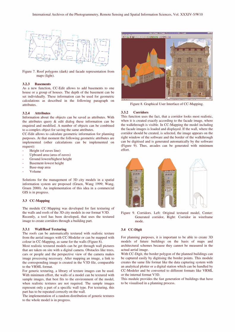
Figure 7. Roof polygons (dark) and facade representation frommaps (light).
3.2.3 BasementsAs a new function, CC-Edit allows to add basements to onehouse or a group of houses. The depth of the basement can beset individually. These information can be used for geometriccalculations as described in the following paragraph onattributes.
3.2.4 AttributesInformation about the objects can be saved as attributes. Withthe attributes query & edit dialog these information can beenquired and modified. A number of objects can be combinedto a complex object for saving the same attributes.CC-Edit allows to calculate geometric information for planningpurposes. At that moment the following geometric attributes areimplemented (other calculations can be implemented onrequest):- Height (of eaves line)- Upboard area (area of eaves)- Ground lowest/highest height- Basement-lowest height- Base-map area- Volume
Solutions for the management of 3D city models in a spatialinformation system are proposed (Gruen, Wang 1999; Wang,Gruen 2000). An implementation of this idea in a commercialGIS is in progress.
3.3 CC-Mapping
The module CC-Mapping was developed for fast texturing ofthe walls and roofs of the 3D city models in our format V3D.Recently, a tool has been developed, that uses the texturedimage to create corridors through a building part.
3.3.1 Wall/Roof TexturingThe roofs can be automatically textured with realistic texturefrom the aerial images with CC-Modeler or can be mapped withcolour in CC-Mapping, as same for the walls (Figure 8).Most realistic textured models can be get through wall picturesthat are taken on site with a digital camera. Obstacles like trees,cars or people and the perspective view of the camera makesimage processing necessary. After mapping an image, a link tothe corresponding image is created in the V3D file, comparableto the VRML format.For generic texturing, a library of texture images can be used.With minimum effort, the walls of a model can be textured withsample images, that best fits to the environment of the model,when realistic textures are not required. The sample imagesrepresent only a part of a specific wall type. For texturing, thispart has to be repeated correctly on the wall.The implementation of a random distribution of generic texturesto the whole model is in progress.
Figure 8. Graphical User Interface of CC-Mapping.
3.3.2 CorridorsThis function uses the fact, that a corridor looks most realistic,when it is created exactly according to the facade image, wherethe walkthrough is visible. In CC-Mapping the model includingthe facade images is loaded and displayed. If the wall, where thecorridor should be created, is selected, the image appears on theright window of the software and the border of the walkthroughcan be digitised and is generated automatically by the software(Figure 9). Thus, arcades can be generated with minimumeffort.
Figure 9. Corridors. Left: Original textured model, Center:Generated corridor, Right: Corridor in wireframemode.
3.4 CC-Digit
For planning purposes, it is important to be able to create 3Dmodels of future buildings on the basis of maps andarchitectural schemes because they cannot be measured in theactual aerial image.With CC-Digit, the border polygon of the planned buildings canbe captured easily by digitising the border points. This modulecreates the same file format like the data capturing system withan analytical plotter or a digital station which can be handled byCC-Modeler and be converted to different formats like VRMLor the internal format V3D.This module provides the fast generation of buildings that haveto be visualised in a planning process.

International Archives of the Photogrammetry, Remote Sensing and Spatial Information Sciences, Vol. XXXIV-5/W10
4 DATA SOURCE
Aerial, satellite imagery and laserscanner data are used as rawdata (see paragraph 2) whereas depending on requirements,different approaches are applied.
4.1 Aerial imagery
At that moment, aerial images are the most common used rawdata (Figure 10). For capturing the 3D point cloud for furtherprocessing in CC-Modeler™, the stereo pairs of the images areneeded. The scale of the images depends on the accuracy that isrequired for the 3D model and is normally about 1:5000 with aforward and a side overlap of 30 and 60 percent respectively. Ifthe images are used for True-Orthophoto, the side overlap issuggested to be 60 percent.Using this data, many building details can be measured from theaerial images and the measurement error is maximal 0,2 meterin height.
Figure 10. 3D city model Karlsruhe (derived from aerialimagery). Courtesy of Vermessungsamt Karlsruhe.
4.2 Satellite imagery
In case of large areas, recently high resolution satellite imageryis used, like the 1-meter panchromatic from Ikonos (Figure 11).The data capturing process is the same as with aerial images,but the accuracy is less, measurement error can be up to 1 meterin height. DTM and Orthophoto can be derived automatically.
Figure 11. 3D city model Izmir (derived from satellite imageryIkonos).
4.3 Laserscanner data
For the generation of 3D city models from laserscanner data, adensity of laserscanner points of more than 2 points/sqm arerequired. Big areas are already surveyed with laserscanner,which is seen as an advantage for the application of this data.The procedure for the calculation of 3D building models fromlaserscanner data uses a tangential plane as a firstapproximation that suits the laserscanner points. From thisgeometric model, edge lines are derived whereas edge lines ofbuilding structures are generated (e.g. eaves lines, ridge linesetc.).These lines are combined to faces to represent the roofplanes. It is possible to automatically derive standard roof typeslike saddleback roofs or pavilion roofs (Steidler et al. 2002).This part is still under development (see example in Figure 12).The accuracy is expected to be 0.3-0.5 meters in height.
Figure 12. 3D city model (derived from laserscanner data).
5 REAL-TIME VISUALISATION
Visualisation is performed by real-time tools like TerrainView(www.viewtec.ch) or CyberWalk (www.muellersystec.de).TerrainView and CyberWalk are two competitive products withinteractive user interfaces. In particular, they are able to displayterrain and buildings as separate objects. Free navigation withina selected geographic area are allowed. Foreground andbackground are displayed with different data subsets whichmeans that a level-of-detail (LOD) is provided and performanceand storage capacity is optimised. Data is compressed anddecompressed during visualisation. Features like flight paths,weather simulation etc. can be provided.For high quality visualisation, the use of a True-Orthophoto isrecommended to avoid that the roof texture is visible on theground beside the building.In the meantime, even the real-time visualisation of the interiorof buildings is possible (Figure 13).
Figure 13. Interior of a church visualised with CyberWalk.

International Archives of the Photogrammetry, Remote Sensing and Spatial Information Sciences, Vol. XXXIV-5/W10
6 CONCLUSIONS
CC-Modeler™ is a tool that uses a semi-automated objectextraction from photogrammetric stereo models to generaterealistic 3D building models. It is independent from thephotogrammetric data capturing system and with the moduleCC-Edit a powerful tool to modify and improve the geometry of3D models is provided.The possibility of the integration of cadastral maps for thegeneration of overhanging roofs, the mapping options and theoption to generate corridors from facade images makes 3D citymodels more realistic.
Hence CC-Modeler™ is a unique tool for generating 3D citymodels efficiently and with a high degree of detail and accuracyand the option of attributation means a next step to a three-dimensional GIS.
7 REFERENCES
Gruen, A., Wang, X. 1998. CC-Modeler: a topology generatorfor 3-D city models, ISPRS Journal of Photogrammetry &Remote Sensing 53(5): pp. 286-295
Gruen, A., Wang, X. 1999. CyberCity Spatial InformationSystem (SIS): A new concept for the management of 3D citymodels in a hybrid GIS. Proc. 20th Asian Conference on RemoteSensing, Hongkong, November 1999, pp. 121-128
Wang, X., Gruen, A. 2000. A hybrid GIS for 3-D city models.International Archives of Photogrammetry and Remote Sensing,vol. 33, part 4/3, pp. 1165-1172
Gruen, A., Wang, X. 2001. News from CyberCity-Modeler.Invited Paper, Third International Workshop on AutomaticExtraction of Man-Made Objects from Aerial and SpaceImages, Monte Verita, Ascona, Switzerland, 10-15 June 2001
Gruen, A., Steidler, F, Wang, X. 2002. Generation andvisualization of 3D-city and facility models using CyberCityModeler. MapAsia 2002, Bankok, August 2002
Steidler F., Ulm K., Wild E., Müller K. 2002. Ableitung von3D-Gebäudemodellen aus Photogrammetrie-, Satelliten- undLaserscannerdaten, interaktive Begehung in Echtzeit.Pressemitteilung InterGeo 2002, Frankfurt, Oktober 2002