IMPROVE THE HAZOP TECHNIQUES TO PREVENT THE …
14
Page 1 of 14 IMPROVE THE HAZOP TECHNIQUES TO PREVENT THE ACCIDENTS CAUSED BY PRESSURE VESSELS T. Sri Ananda Atreya M.E. Industrual Safety Engineering Excel college of Engineering and Technology Erode, India Dr.E.Palaniswamy, M.E., M.B.A, Ph.D. Principal Excel college of Engineering and Technology Erode, India Abstract— Pressure vessels are commonly used in industries and healthcare to store both liquid and gases under required pressure and temperature limit. This pressure and temperature comes from an external source or by the expansion of the product that is stored or by the application of heat from a direct or indirect source or any combination of them. The differential pressure and temperature is dangerous, and fatal accidents have occurred in the history of pressure vessel maintenance and operation. The bursting of pressure vessel results in loss of lives and property. Consequently, pressure vessel design, manufacturing, and operations are regulated by various engineering authorities backed by legislation. This paper mainly focuses on the reasons behind pressure vessel failure, and accidents that create hazards such as poisoning, asphyxiation, fires, and explosion. So, preventive measures are to be taken during different stages of design, manufacturing, installation, commissioning, operation, and decommissioning of the pressure vessels in order to avoid accidents and improve the hazard awareness techniques to prevent accidents. Keywords— Pressure vessels, Temperature, Fatal Accidents, Pressure Vessel Design, Explosion Hazards, Hazard Awareness. I. INTRODUCTION The pressure vessels (i.e. cylinder or tanks) are used to store fluids under pressure. Pressure vessel is defined as a container with a differential pressure between inside and outside. The inside pressure is usually higher than the outside. The fluid inside the vessel may undergo a change in state as in the case of steam boiler or may combine with other reagent as in the case of chemical reactor. Pressure vessel often has a combination of high pressure together with high temperature and in some cases flammable fluids or highly radioactive material. Because of such hazards it is imperative that the design be such that no leakage can occur. Pressure vessel and tank are in fact essential to the chemical, petroleum, petrochemical and nuclear industry. It is in the class of equipment that the reaction, separation and storage of raw material occur. In the same word, pressurized equipment is required for a wide range of industrial plant for storage and manufacturing purpose. In the case of shell, opening requiring reinforcement in vessel under internal pressure the metal removed must be replaced by the metal of reinforcement. In addition to providing the area of reinforcement, adequate welds must be provided to attach the metal of reinforcement and the induced stresses must be evaluated. Materials used for reinforcement shall have an allowable stress value equal to or greater than of the material in this vessel wall except that, when such material is not available, lower strength material may be used; provided, the reinforcement is increased in inversed proportion to the ratio of the allowable stress values of the two materials to the ratio of the two materials to compensate for the lower allowable stress value of any reinforcement having a higher allowable stress value than that of the vessel wall. II. PROBLEM DESCRIPTION Tanks and vessels that store or receive fluids under pressure are called pressure vessel. A Pressure Vessels are vital component, largely supporting the day to day activities of several heavy industries including energy, metal, mining, power generation, and oil and gas. A pressure vessel is defined as a container with a pressure differential between inside and outside. The inside pressure is usually higher than the outside. The fluid inside the vessel may undergo a change in state as in the case of steam boiler or may combine with other reagent as in the case of chemical reactor or may be subjected to boiling and expansion in case of cryogenic pressure vessels.. Pressure vessel often has fluids with a combination of high pressure together with high temperature, low pressure with high temperature, high pressure with low temperature and in some cases flammable fluids or highly radioactive materials. Because of such hazards it is imperative that the design be such that the vessel is capable of containing the fluid in a safe manner during normal operating conditions also no leakage should occur. These pressure vessels include vacuum insulated evaporators, vacuum insulated storage tanks, vacuum insulated transport trucks, cold convertors, puff insulated aluminum vessels, cryogenic containers etc. that are responsible for handling, storing, and conveying substances under pressure. In short, pressure vessels for heavy industries are designed to handle high risk activities However, most of the time careless attitude of people working in the vicinity of pressure vessel, technical faults, improper maintenance, improper design and operations etc. invites several cataclysmic incidents. In the past, there have been many accidents reported with disastrous consequences. Although, accidents pertaining to pressure vessels might not be fully eliminated, we can at least take simple measures to minimize the risk and likelihood of such mishaps. III. TYPES OF PRESSURE VESSELS Pressure vessels are ubiquitous in modern society and commonly go unseen by the general public. However, industrial pressure vessels are essential to the continual processing and manufacturing by industrial and commercial concerns and therefore have a direct impact on the both the economic and physical wellbeing of society. With this complex interaction ongoing, it would be easy to assume that pressure vessels are widely varied in design, when in fact, there are three common types and these are found in many industrial and commercial applications. There are specialized application pressure vessels such as reactors and
Transcript of IMPROVE THE HAZOP TECHNIQUES TO PREVENT THE …

Page 1 of 14
IMPROVE THE HAZOP TECHNIQUES TO PREVENT THE ACCIDENTS CAUSED BY
PRESSURE VESSELS T. Sri Ananda Atreya
M.E. Industrual Safety Engineering Excel college of Engineering and Technology
Erode, India
Dr.E.Palaniswamy, M.E., M.B.A, Ph.D. Principal
Excel college of Engineering and Technology
Erode, India
Abstract— Pressure vessels are commonly used in industries and healthcare to store both liquid and gases under required pressure and temperature limit. This pressure and temperature comes from an external source or by the expansion of the product that is stored or by the application of heat from a direct or indirect source or any combination of them. The differential pressure and temperature is dangerous, and fatal accidents have occurred in the history of pressure vessel maintenance and operation. The bursting of pressure vessel results in loss of lives and property. Consequently, pressure vessel design, manufacturing, and operations are regulated by various engineering authorities backed by legislation. This paper mainly focuses on the reasons behind pressure vessel failure, and accidents that create hazards such as poisoning, asphyxiation, fires, and explosion. So, preventive measures are to be taken during different stages of design, manufacturing, installation, commissioning, operation, and decommissioning of the pressure vessels in order to avoid accidents and improve the hazard awareness techniques to prevent accidents. Keywords— Pressure vessels, Temperature, Fatal Accidents, Pressure Vessel Design, Explosion Hazards, Hazard Awareness.
I. INTRODUCTION
The pressure vessels (i.e. cylinder or tanks) are used to store fluids under pressure. Pressure vessel is defined as a container with a differential pressure between inside and outside. The inside pressure is usually higher than the outside. The fluid inside the vessel may undergo a change in state as in the case of steam boiler or may combine with other reagent as in the case of chemical reactor. Pressure vessel often has a combination of high pressure together with high temperature and in some cases flammable fluids or highly radioactive material. Because of such hazards it is imperative that the design be such that no leakage can occur. Pressure vessel and tank are in fact essential to the chemical, petroleum, petrochemical and nuclear industry. It is in the class of equipment that the reaction, separation and storage of raw material occur. In the same word, pressurized equipment is required for a wide range of industrial plant for storage and manufacturing purpose. In the case of shell, opening requiring reinforcement in vessel under internal pressure the metal removed must be replaced by the metal of reinforcement. In addition to providing the area of reinforcement, adequate welds must be provided to attach the metal of reinforcement and the induced stresses must be evaluated. Materials used for reinforcement shall have an allowable stress value equal to or greater than of the material in this vessel wall except that, when such material is not available, lower strength material may be used; provided, the reinforcement is increased in inversed proportion to the ratio of the allowable stress values of the two materials to the ratio of the two materials to compensate for the lower allowable stress value of any reinforcement
having a higher allowable stress value than that of the vessel wall.
II. PROBLEM DESCRIPTION
Tanks and vessels that store or receive fluids under pressure are called pressure vessel. A Pressure Vessels are vital component, largely supporting the day to day activities of several heavy industries including energy, metal, mining, power generation, and oil and gas. A pressure vessel is defined as a container with a pressure differential between inside and outside. The inside pressure is usually higher than the outside. The fluid inside the vessel may undergo a change in state as in the case of steam boiler or may combine with other reagent as in the case of chemical reactor or may be subjected to boiling and expansion in case of cryogenic pressure vessels.. Pressure vessel often has fluids with a combination of high pressure together with high temperature, low pressure with high temperature, high pressure with low temperature and in some cases flammable fluids or highly radioactive materials. Because of such hazards it is imperative that the design be such that the vessel is capable of containing the fluid in a safe manner during normal operating conditions also no leakage should occur. These pressure vessels include vacuum insulated evaporators, vacuum insulated storage tanks, vacuum insulated transport trucks, cold convertors, puff insulated aluminum vessels, cryogenic containers etc. that are responsible for handling, storing, and conveying substances under pressure. In short, pressure vessels for heavy industries are designed to handle high risk activities However, most of the time careless attitude of people working in the vicinity of pressure vessel, technical faults, improper maintenance, improper design and operations etc. invites several cataclysmic incidents. In the past, there have been many accidents reported with disastrous consequences. Although, accidents pertaining to pressure vessels might not be fully eliminated, we can at least take simple measures to minimize the risk and likelihood of such mishaps.
III. TYPES OF PRESSURE VESSELS
Pressure vessels are ubiquitous in modern society and commonly go unseen by the general public. However, industrial pressure vessels are essential to the continual processing and manufacturing by industrial and commercial concerns and therefore have a direct impact on the both the economic and physical wellbeing of society. With this complex interaction ongoing, it would be easy to assume that pressure vessels are widely varied in design, when in fact, there are three common types and these are found in many industrial and commercial applications. There are specialized application pressure vessels such as reactors and

Page 2 of 14
regeneration vessels; however most correspond to the three common types.
A. Storage Vessels
The most prolific of all pressure vessels are the various storage vessels required for industrial processes. These typically correspond to either the vertical or horizontal variety, although some spherical storage vessels are in use. Used primarily to store liquids, these pressure vessels are also available in a range of sizes. Depending on the exact role or product to be stored, they are constructed using different materials with carbon steel being the most common material type. In many cases, internal liners of a different material are used in addition to the vessel's external material. This allows a material to be used for the external construction that would be at a detriment if exposed to the product. Therefore allowing the storage vessel to be produced for a less cost, than that of using a special material.
Cylindrical pressure vessel
Spherical pressure vessel
A.1. Cylindrical Pressure Vessel
Cylinders are widely used for storage due to their being less expensive to produce than spheres. However, cylinders are not as strong as spheres due to the weak point at each end. This weakness is reduced by hemispherical or rounded ends being fitted. If the whole cylinder is manufactured from thicker material than a comparable spherical vessel of similar capacity, storage pressure can be similar to that of a sphere.
Horizontal Pressure Vessel Vertical Pressure vessel
A.1.1. Horizontal Pressure Vessel
Industrial facilities show a large number of constructions and structural components (ASCE 1997). As materials are concerned, it is easy to recognize that both reinforced concrete and steel constructions are commonly used, even in combination like composite structures. Large installation can be characterized by use of pre-stressed members, especially when long spans are required. However, it is worth nothing that a large variety of functions have to be accomplished by structural components so that the latter can be classified as building like structures and non-building like structures. Building structures typically found in an industrial plant include administration buildings, control buildings, substations, warehouses, firehouses, maintenance buildings, and compressor shelters or buildings. Other structures, whose structural systems do not resemble those of buildings, are classified as non-building-like structures. Above-ground pressurized tanks are examples of such class of constructions.
Fig.1. Horizontal Pressure vessel
A.1.2. Vertical Pressure Vessel
Air-chamber - the number of units and their description, the highest operating pressure and temperature of the media, the opening pressure and the safety valve type.
Aquamat - the number of units and their description, the highest operating pressure and temperature of the media, the scale drawing showing the position and size of the required necks, the manometer range, the opening pressure and the relief valve type, type of the media to maintain the pressure cushion, the purpose of operational utilization
Expander - the number of units and their description, operating pressure and temperature in the expander, the scale drawing showing the position and the size of the required necks, DN and PN of the nozzle necks, manometer range, as well as DN, PN, opening pressure and the safety valve capacity, the maximum operating pressure, temperature, volume and type of incoming media (surface blowdown, discharge, etc.), data on the dispersal of non-expanded water, e.g. electric regulation, pipe loop, etc., and the information about the connection of the released steam, for example into a steam network, into the atmosphere.
Fig.2. Vertical Pressure Vessel

Page 3 of 14
A.1.3. Spherical Pressure Vessel
This type of vessel is preferred for storage of high pressure fluids. A sphere is a very strong structure. The even distribution of stresses on the sphere's surfaces, both internally and externally, generally means that there are no weak points. Spheres however, are much more costly to manufacture than cylindrical vessels. Storage Spheres need ancillary equipment similar to tank storage - e.g. Access manholes, Pressure / Vacuum vent that is set to prevent venting loss from boiling and breathing loss from daily temperature or barometric pressure changes, Access ladders, Ear thing points, etc. An advantage of spherical storage vessels is, that they have a smaller surface area per unit volume than any other shape of vessel. This means, that the quantity of heat transferred from warmer surroundings to the liquid in the sphere, will be less than that for cylindrical or rectangular storage vessels.
Fig.3. Spherical Pressure Vessel
B. Steam Boiler
A pressure vessel is a tank designed to hold fluids (gases or liquids or both) at a high pressure without bursting. A boiler is a tank to hold a liquid (often water) so that it can be boiled by a heat source. Often the purpose is to produce steam under pressure to power something (such as a turbine to generate electricity or to propel a steam engine train). Boilers often have to withstand high pressure, in which case they would also be considered a pressure vessel. But it's possible that a boiler is just there to create hot water or steam at normal atmospheric pressure and the fluid is moved from the boiler out along some pipes by a pump. This could, for example, be part of a heating system for a building. In most cases a boiler would be designed to withstand pressure.
Fig.4. Steam Boiler
C. Heat Exchanger
The second most common type, and almost as prolific as storage vessels, is the heat exchanger. Found in almost every aspect of life, from food service to industrial plants, heat exchangers make modern processing and manufacturing possible. It is widely known that heat, by its very nature, can be a negative aspect to many industrial processes and as such has to be removed or reused to provide for this concern. Thus it is critical that any heat exchanger design have an emphasis on the material chosen to ensure that the vessel can be operated at peak optimization for extended periods. Carbon steel is a common material but usually more stringent alloys are used to ensure longevity and proper functioning.
Fig.5. Heat Exchanger
IV. PRESSURE VESSEL COMPONENTS
The main components of pressure vessel are,
A. Vessel shell
B. Vessel nozzle
C. Vessel supports
D. Vessel Head
A. Vessel Shell
It is the primary component that contains the pressure.
Page 4 of 14
Pressure vessel shells in the form of different plates are welded together to form a structure that has a common rotational axis. Horizontal drums have cylindrical shells and are constructed in a wide range of diameter and length. The shell sections of a tall tower may be constructed of different materials, thickness and diameters due to process and phase change of process fluid. Shell of a spherical pressure vessel is spherical as well.
B. Vessel nozzle
If the vessel has multiple nozzles projecting from the main cylinder, then set the Type of model to generate drop-down box in the General tab to multiple nozzles. This will deactivate the other tabs. The input is used only for a single nozzle vessel. To generate a plate or shell element model, select the Plate/shell option in the Type of pipes generated drop-down box on the General tab. To generate a brick element model, select the Solid option. Note that the Preview Area does not show the thicknesses; it continues to show the plate/shell mesh.
Since the main cylinder can contain multiple nozzles, the following buttons on the Cylinder with Multiple Nozzles input dialog are used to manipulate the various nozzles:
To create a nozzle on the cylinder, press the Add new nozzle button in the Geometry tab. Once you are done defining the nozzle, press the Add new nozzle button again to create the next nozzle. Repeat this until all nozzles have been added.
To modify the properties of an existing nozzle, select the nozzle number in the drop-down box in the Nozzles on Cylinder section and press the Modify nozzle button.
To remove a nozzle, select the nozzle number in the drop-down box in the Nozzles on Cylinder section and press the Remove nozzle button.
If two nozzles are identical but are located at different positions, you can define the nozzle properties for one nozzle; select the nozzle number in the drop-down box in the Nozzles on Cylinder section and press the Duplicate nozzle button. A new nozzle will be created. You can then modify the position of the new nozzle.
C. Vessel Support
Support is used to bear all the load of pressure vessel, earthquake and wind loads. It is considered to be the non-pressurized part of the vessel. There are different types of supports which are used depending upon the size and orientation of the pressure vessel.
They are,
Saddle support
Skirt support
Leg support
Lug support
C.1. Saddle Support
Horizontal drums are typically supported at two locations by saddle support.
It spreads over a large area of the shell to prevent an excessive local stress in the shell at support point.
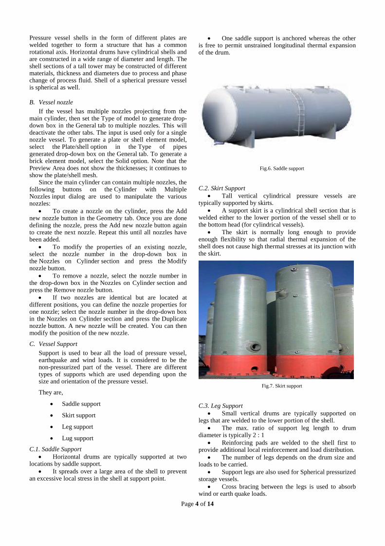
One saddle support is anchored whereas the other is free to permit unstrained longitudinal thermal expansion of the drum.
Fig.6. Saddle support
C.2. Skirt Support
Tall vertical cylindrical pressure vessels are typically supported by skirts.
A support skirt is a cylindrical shell section that is welded either to the lower portion of the vessel shell or to the bottom head (for cylindrical vessels).
The skirt is normally long enough to provide enough flexibility so that radial thermal expansion of the shell does not cause high thermal stresses at its junction with the skirt.
Fig.7. Skirt support
C.3. Leg Support
Small vertical drums are typically supported on legs that are welded to the lower portion of the shell.
The max. ratio of support leg length to drum diameter is typically 2 : 1
Reinforcing pads are welded to the shell first to provide additional local reinforcement and load distribution.
The number of legs depends on the drum size and loads to be carried.
Support legs are also used for Spherical pressurized storage vessels.
Cross bracing between the legs is used to absorb wind or earth quake loads.

Page 5 of 14
Fig.8. Leg support
C.4. Lug Support
Vertical pressure vessels may also be supported by lugs.
The use of lugs is typically limited to pressure vessels of small and medium diameter (1 to 10 ft)
Also moderate height to diameter ratios in the range of 2:1 to 5:1
The lugs are typically bolted to horizontal structural members in order to provide stability against overturning loads.
Fig.9. Lug support
D. Vessel Head
All the pressure vessels must be closed at the ends by heads (or another shell section).
Heads are typically curved rather than flat.
The reason is that curved configurations are stronger and allow the heads to be thinner, lighter and less expensive than flat heads.
Heads can also be used inside a vessel and are known as intermediate heads.
These intermediate heads are separate sections of the pressure vessels to permit different design conditions.
V. CAUSES OF PRESSURE VESSEL ACCIDENTS
A. Main Causes of Pressure vessel accidents
The main causes of failure of a pressure vessel are as follows:
Faulty Design
Operator error or poor maintenance
Operation above max allowable working pressures
Change of service condition
Over temperature
Safety valve
Improper installation
Corrosion
Cracking
Welding problems
Erosion
Fatigue
Stress
Improper selection of materials or defects
Low –water condition
Improper repair of leakage
Burner failure
Improper installation
Fabrication error
Over pressurization
Failure to inspect frequently enough
Erosion
Creep
Embrittlement
Unsafe modifications or alteration
Unknown or under investigation
There are a variety of conditions that cause deterioration in pressure vessels. The common conditions are listed and described below:
a. Corrosion: Corrosion is one of the most prevalent conditions found in pressure vessels. The following types of corrosion are commonly found:
1. Pitting Shallow - isolated, scattered pitting over a small area that does not substantially weaken the vessel. It could, however, eventually cause leakage.
2. Line corrosion - This is a condition where pits are connected, or nearly connected, to each other in a narrow band or line. Line corrosion frequently occurs in the area of intersection of the support skirt and the bottom of the vessel and at the liquid-vapor interface.
3. General corrosion - This is corrosion that covers a considerable area of the vessel. When this occurs, consider the safe working pressure of the vessel that is directly related to the remaining material thickness.
4. Grooving - This type of corrosion is a form of metal deterioration caused by localized corrosion. It may be accelerated by stress concentration. Grooving may be found adjacent to riveted lap joints or welds and on flanged surfaces, particularly the flanges of unstayed heads.

Page 6 of 14
5. Galvanic corrosion - Two dissimilar metals in contact with each other and with an electrolyte (i.e., a film of water containing dissolved oxygen, nitrogen, and carbon dioxide) constitute an electrolyte cell, and the electric current flowing through the circuit may cause rapid corrosion of the less noble metal (the one having the greater electrode potential). This corrosion mechanism is most active when there are large differences between the electrode potentials of the two metals, but galvanic corrosion may also exist with relatively minor changes of alloy composition (i.e., between a weld metal and the base metal). Neutral (i.e., an oxide coating on aluminum) or protective coatings may inhibit galvanic corrosion, but in most instances, the metals or alloys must be selected on the basis of intrinsic resistance to corrosion. In pressure vessels, the effects of galvanic corrosion are most noticeable at rivets, welds, and flanged and bolted connections.
b. Fatigue: Stress reversals (such as cyclic loading) in parts of equipment are common, particularly at points of high secondary stress. If stresses are high and reversals frequent, failure of parts may occur because of fatigue. Fatigue failures in pressure vessels may also result from cyclic temperature and pressure changes. Locations where metals having different thermal coefficients of expansion are joined by welding may be susceptible to thermal fatigue.
c. Creep: Creep may occur if equipment is subject to temperatures above those for which the equipment is designed. Since metals become weaker at higher temperatures, such distortion may result in failure, particularly at points of stress concentration. If excessive temperatures are encountered, structural property and chemical changes in metals may also take place that may permanently weaken equipment. Because creep depends on time, temperature, and stress, the actual or estimated levels of those quantities should be used in any evaluations.
d. Temperature: At sub-freezing temperatures, water and some chemicals handled in pressure vessels may freeze and cause failure. Carbon and low alloy steels may be susceptible to brittle failure at ambient temperatures. A number of failures have been attributed to brittle fracture of steels that were exposed to temperatures below their transition temperature and which were exposed to pressures greater than 20 percent of the hydrostatic test pressure. However, most brittle fractures have occurred on the first application of a particular stress level (that is, the first hydrostatic test or overload). Special attention should be given to low-alloy steels because they are prone to temper embrittlement. (Temper embrittlement is defined as a loss of ductility and notch toughness caused by postweld heat treatment or high temperature service, service above 700 degrees Fahrenheit.
e. Hydrogen embrittlement: Hydrogen embrittlement is a loss of strength or ductility in steels caused by atomic hydrogen dissolved in the steel. It is a low
temperature phenomenon, seldom encountered above 200 degrees Fahrenheit, and most often occurs as a result of hydrogen evolved from aqueous corrosion reactions. It can vary in appearance and can occur in differing environments, thus giving rise to the various terms by which it is known, including sulfide stress cracking, wet H2S cracking, hydrogen stress cracking, blistering, blister cracking, hydrogen-induced cracking (HIC), and stress-oriented hydrogen-induced cracking (SOHIC). Weld under bead cracking (also known as delayed cracking and cold cracking) is also a form of hydrogen embrittlement; however, in this case, the hydrogen comes from the welding operation rather than from a corrosion reaction.
Some forms of hydrogen embrittlement require an applied stress or residual stress for cracking to occur (sulfide stress cracking, SOHIC, weld underbead cracking), and others occur in the absence of applied or residual stress, the internal pressure from the recombined hydrogen gas being sufficient to cause the damage (blistering, HIC).
Susceptibility to sulfide stress cracking and similar forms of hydrogen embrittlement depends on the strength of the steel. Higher strength steels are more susceptible. The strength level at which susceptibility arises depends on the severity of the environment that the steel is exposed to. Hydrogen sulfide, hydrogen cyanide, and arsenic, in aqueous solutions, all greatly increase the severity of the environment regarding hydrogen embrittlement by increasing the amount of hydrogen that is absorbed by the steel during the corrosion reaction. In hydrogen sulfide environments, cracking can generally be avoided by using steels with a strength level below that equivalent to a hardness of Rockwell C-22.
Similarly, weld under bead cracking is caused by hydrogen dissolved in a hard, high- strength, weld-heat affected zone. Practicing low hydrogen welding to minimize dissolved hydrogen or using high preheat or post-weld heat treatment to reduce heat affected zone hardness will reduce the likelihood of weld under bead cracking in a susceptible steel.
Hydrogen embrittlement is reversible as long as no physical damage, e.g., cracking, has occurred in the steel. If the atomic hydrogen is removed from the steel before any damage occurs, for example by heating for a short time in the absence of hydrogen to between 300 and 400 F, normal mechanical properties will be restored.
Cracking that can occur in vessels operating in aqueous H2S service (i.e., wet H2S cracking) will not always be readily apparent on visual inspection. Other methods, such as magnetic particle (including wet fluorescent) or liquid penetrant, may be required to reveal the cracks.
Welding procedures, repair methods, and inspection procedures must include careful consideration of potential failure in corrosive environments, including failure from the various forms of hydrogen embrittlement.

Page 7 of 14
f. Stress corrosion cracking: Cracking of a metal caused by the combined action of stress and a corrosive environment. Stress corrosion cracking only occurs with specific combinations of metal and environment. The stress required may be either applied or residual. Examples of stress corrosion cracking include chloride stress corrosion cracking of stainless steels in hot, aqueous chloride solutions and ammonia stress corrosion cracking of brass in ammonia solutions (season cracking).
Corrosion alone is not a good indicator of the likelihood of a particular environment to cause stress corrosion cracking in a particular metal. Solutions that are highly corrosive to a material almost never promote stress corrosion cracking.
The principal variables affecting stress corrosion cracking are tensile stress, service temperature, solution chemistry, duration of exposure, and metal properties. Sufficiently modifying any one of these parameters can reduce or eliminate the possibility of stress corrosion cracking occurring in service.
B. Faulty design and manufacturing of vessels
The faulty design is a common source for defects such as hard inclusions, blisters by trapped gas and micro-cracks that developed during fast cooling of the welded joint. Present rules in fabrication codes are aimed to reduce the probability of failures in pressure vessels subjected to cyclic pressure or vibrations.
Reactor pressure vessels (RPV) and pipelines are commonly constructed using welded pressure vessel grade steels and stainless steel liners. These pressure vessel steels required good ductility and weld-ability. The vessels wall materials used in oil refineries and chemical plants undergoes both physical and chemical changes because of various separation and conversion processes. These steel vessels operate in corrosive and high temperature environments. The operating temperature typically ranges from -29 to 427 ⁰C.
Fig.10. Welded joint failure
Prolonged exposure of the steel to these conditions could lead to deleterious effects such as embrittlement, loss of toughness, creep rupture of the steel and a shift in ductile-to-brittle transition temperature (DBTT) to higher temperatures Hence, vessels constructed with the steels, brittle fracture
triggered by trans-granular cleavage in the DBTT region represents a potentially catastrophic failure mode.
Therefore, one can term, cleavage fracture in the DBTT region exhibits a ‘weakest link’ phenomenon. The occurrence of brittle fracture depends on the toughness of weld metal (WM) and of the heat affected zone (HAZ), which is generally lower than the base metal. The DBTT depends on many factors such as neutron flux, in case of nuclear vessel material, loading rates during service and outages, etc. which is usually experimentally captured by testing Charpy impact specimens. Commercial industry requires pressure vessel steel with sufficient strength and toughness, for both economic and safety reasons. Failures of pressure vessels and pressure piping related accidents are often fatal and involved loss of capital investment. The application of immense heat in a welded joint of a pressure vessel steel, to fuse the base plate and weld metal (electrode) for strong permanent joint results in a mechanical and metallurgical in homogeneity due to the weld thermal cycle in the base metal (BM), the HAZ and the WM. Weldments are thus, identified as a particular concern because they are often a life-limiting feature, and since existing ASME Boiler & Pressure Vessel (B&PV) code rules do not adequately consider the high-temperature creep failure modes that can arise as a function of geometry, loading and material combination. Particularly tensile residual stresses near the weld area and HAZ may cause stress raising, fatigue failure and fracture.
Various studies showed that cracks have been found in different regions of the weld with different orientation in the weld zone, such as centerline cracks, transverse cracks and micro-cracks in the underlying WM or HAZ , thus rendering this region to be the most susceptible for crack initiation and growth. Once structural crack is present, fracture mechanics is employed to characterize the crack growth behavior as function of working load and other parameters. Steels in general are ductile at high temperatures and brittle at lower temperature. This material behavior is normally presented as the ductile-brittle transition curve and plotted as fracture energy or toughness versus temperature. A typical ductile-brittle transition curve is shown in Figure. Pressure vessels, under normal operating conditions, are designed to operate at temperature above the onset of upper shelf toughness in order to avoid the brittle fracture.
During planned outages and emergency start-up / shutdown sequences of the plants, these vessels undergo severe thermal. gradients thorough out their service life. The existence of these thermal gradient’s has been a concern in many welded structures since it increases the crack driving force and reduces resistance to brittle fracture. Moreover, in reactor pressure vessel the criteria for safety include consideration of the effect of neutron irradiation over time on the ferritic steels which makes the steel brittle and shifts the material’s ductile-to-brittle transition curve to a higher temperature range (the dashed line in Figure 1). The shift decreases operation margins in both the temperature and pressure and is inevitable in the aging process of reactor pressure vessel.
C. Operator Negligence
Pressure vessels and piping systems are designed, fabricated, and operated to ensure very high levels of structural integrity, because the consequences of structural

Page 8 of 14
failures can be severe. Catastrophic ruptures can produce high-energy missiles, and cause damage to adjacent equipment and structures along with injuries and fatalities to workers and the public. Failure modes of a less catastrophic nature, such as leaks, can release hazardous and flammable materials that can also present significant hazards. While service experience over the last century shows an excellent record of reliability, efforts continue to improve and maintain the reliability of vessels and piping systems. This chapter describes methods to predict probabilities of failure and to quantify the consequences of such failures. These methods can be applied to vessels or piping systems taking into consideration component-specific design features, materials of construction, fabrication practices, operating stresses and temperatures, environmental factors, operating and maintenance practices, and in-service inspection programs.
D. Corrosion and cracking
Most pressure vessels are subject to some kind of corrosion or erosion. In most cases, corrosion can be minimized by either designing intelligently or controlling the environment carefully. In other situations corrosion is difficult to prevent. A vessel containing a corrosive substance kept in motion by a stirring paddle will deteriorate more rapidly for example. Corrosion can attack the pressure vessel uniformly or locally. Large area corrosion wastes away materials uniformly from the vessel surface. Although this can lead to general reduction of thickness and strength in the long run, it is far less malicious comparing to localized corrosion. Precautions such as allowing extra thickness according to service life can be easily taken by designers.
Local attack on the other hand is more of an enemy to designers. Stress concentrations are produced at pits; grooves and notches start to form; and ultimately cracks cut through the weakest point of the vessel.
Fig.11. Failure due to corrosion and cracking
Corrosion and stress are actually interacting together and locally corroded metal experiences more stresses under normal pressure. And in return when the metal becomes more stressed, it corrodes faster. This combined action creates a vicious cycle that brings to sudden rupture and must be avoided at any cost.
NDK Crystals operated a factory producing crystals in an industrial area in Belvedere, Illinoi. They produced crystals for a variety of products, especially for electronic devices. The facility housed 8 massive cylindrical pressure
vessels with 8 inch thick steel walls, standing 50 feet tall. Inside, Silica was mixed with corrosive sodium hydroxide solution at extremely high pressure and temperatures. The vessels were kept sealed for one hundred fifty days to grow large crystals of quartz. The silica and sodium hydroxide react with the ions in the walls of the steel vessels forming a layer of sodium ion silicate or acmite.
The company believed that this ion coating would protect the vessel from the corrosive effect of the chemical inside. Over the years, NDK was warned that corrosion may compromise the walls of the pressure vessels yet the company continued to operate those vessels without performing recommended inspections. In 2009, one of the vessels suddenly exploded, killed a truck driver, and caused million dollars of damage. The explosion was due to stress corrosion cracking in the vessels that had not been inspected for years.
E. Use of poor quality of materials
Carbon Steel – Carbon steel provides a number of advantages as a pressure vessel material. In addition to being highly resistant to corrosion, shock, and vibration, it possesses a high tensile strength — making it ideal for demanding tank applications in a wide range of industrial processes. It also retains strength at minimal thicknesses, which reduces the amount of material needed for tank fabrication, thereby lowering fabrication costs. Carbon steel is also highly recyclable and accounts for more recycled weight annually than aluminum, plastic, paper, and glass combined. In fact, approximately 50% of its production comes from reclaimed materials.
Stainless Steel – Like carbon steel, stainless steel offers high strength at low thickness. Also like carbon steel, it is highly recyclable. There are a number of different types of stainless steel. Type 304, for instance, is widely known for its superior chemical and corrosion resistance. Type 304L, on the other hand, has low carbon content and exhibits excellent weldability. Choosing the correct type of stainless steel will ultimately depend on the unique requirements of the application that the pressure vessel is being used in. In general, however, it is ideal for tanks and vessels that are exposed to the natural environment (humidity, sunlight, etc.) or high temperatures.
Hastelloy – Hastelloy pressure vessels are widely used for chemical, petrochemical, and oil and gas applications. With proper maintenance, they can last for decades, creating great cost-efficiency over their entire lifecycle. Their inherent reliability also reduces maintenance-related downtime.
Hastelloy is extremely resistant to corrosive liquids and provides protection against both localized and uniform attack. It is also very durable and resistant to cracking. Moreover, it is extremely workable (easy to weld or fabricate) and is available in a wide range of types (B2, S, C, C276, etc.), which makes it suitable for a broad range of tank applications and industries.
Nickel Alloy – Nickel alloy comes in a variety of grades. For instance, chromium can be added to nickel alloy to provide more heat resistance. Copper can also be added for use in salt-water environments. Perhaps the most notable use of nickel alloy tanks is in Liquefied Natural Gas (LNG) applications.

Page 9 of 14
It’s important to note that the manufacturing process for this alloy can be more complex than with other amalgams. During tank fabrication, only the purest materials should be used in order to ensure its integrity. Despite this complexity and associated cost, nickel alloy has plenty to offer as a pressure vessel material – providing excellent corrosion resistance, as well as protection against thermal expansion.
Fig.12. Failure due to use of poor quality of materials
Aluminum – Aluminum is often considered as an alternative to stainless steel for many pressure vessel applications. It is roughly three times less dense than stainless steel and can maintain high tensile strength with certain heat treatments and alloy compositions. One of the most significant advantages of aluminum is that it is cheaper and much easier to machine than stainless steel. In many instances, however, labor costs may be higher, as some aluminum tank fabrication requires the use of special welding techniques. Because of its lower density, aluminum is typically not suitable for pressure vessels that are exposed to extremely high pressures.
Titanium – Like copper nickel alloys, titanium provides a number of advantages in salt-water environments and its inherent resistance to corrosion reduces cleaning and maintenance requirements. It maintains strength and rigidity even at lower thicknesses and facilitates more efficient heat-transfer than many other types of metal as well. Titanium is also known for its ability to maintain its structural properties over long periods of time. It is widely used in power station condensers and similar applications.
F. Improper repair of leakage
Most practicing engineers and technologists have had little or no formal academic training on failures, failure prevention and repair of pressure vessels, piping, boilers and rotating machinery. There are no undergraduate programs to cover this subject in North America, and only a handful of universities offer graduate courses in this area. Most reliability practitioners have formal academic training in other technical disciplines and become experienced in areas of failure prevention by virtue of their job training and work experience. This course provides an opportunity to learn from the practical experience and vast knowledge of the instructor and to gain insight into proven practical methods that can be applied for assessing and extending equipment useful life. An integrated approach for examining clearly illustrated field failures and application of the knowledge in preventing failures and reinforced by case studies is presented. The case studies vividly describe sequential repair procedures
enabling participants to learn their real options before starting to rip out sections of pipe and machinery. Reliability in design, manufacturing and maintenance is also examined. The enhanced reliability can significantly reduce overall costs because of reduced support costs due to fewer failures. Additionally, costs associated with catastrophic accidents which are potentially enormous and include regulatory and legal risks are eliminated.
G. Excessive temperature
The conditions, mechanisms, and/or degradations that can cause the low toughness need to be considered. Vessels and pipes with low toughness do not fail unless subjected to high enough stresses to cause failure. High residual stresses, as high as the yield stress, can be present due to welding and heat treatments.
Design temperature is the temperature that will be maintained in the metal of the part of the vessel being considered for the specified operation of the vessel. For most vessels, it is the temperature that corresponds to the design pressure. However, there is a maximum design temperature and a minimum design temperature (MDMT) for any given vessel. The MDMT shall be the lowest temperature expected in service or the lowest allowable temperature as calculated for the individual parts. Design temperature for vessels under external pressure shall not exceed the maximum temperatures.
Fig.13. Failure due to excessive temperature
VI. PRESSURE VESSEL ACCIDENTS AND ITS EFFECTS
Below are six examples of major accidents involving pressure vessels that have occurred in the past 7 years;
Failure of the clamping system on a pressure vessel lid, which caused the lid to fly off and hit a worker at Clariant Life Science Molecules (UK) Limited’s plant in Sandy croft, Flint shire in October 2003. The worker named Giancarlo Coletti sustained serious injuries to his right arm.
An explosion at Algeria’s largest refinery in port city of Skikda, Algiers. The huge explosion at its key gas installation killed 23 people on 20 January 2004.
A pressure vessel weighing 22680 kg (50,000 pounds) exploded at Marcus Oil in 2004, a Chemical plant in Houston, Texas, throwing heavy fragments into the community, which damaged a church, shattered car windows, nearby buildings experienced significant structural and interior damage due to improper

Page 10 of 14
modification and faulty welds of the vessel. Pieces of shrapnel metal weighing over 450kg travelled at extremely high speeds up to a half-mile before landing on nearby highways and railways. A large portion of the plant was destroyed, half the state was without phone or electricity, 3 plant workers were killed and several residents cut by flying glass.
The Buncefield (UK’s fifth largest depot) accident on Sunday 12 December 2005 that injured 43 people readily comes to the mind. Twenty petrol tanks were involved in the Buncefield blaze rage; each held three million gallons of fuel. Over 2,000 people were evacuated from the neighbourhood of the depot during the accident.
Pressure vessel failure in Houston, United States, in the summer of 2008 killed a veteran supervisor when a heat exchanger exploded in a resin-production facility.
Two employees killed at an oil refinery in southeast New Mexico, USA and two others critically injured after a storage tank exploded into flames on 03 March 2010.
The other important accidents that occurred in the history of pressure vessels are:
A. Feyzin Explosion
On Jan. 4, 1966, an operation to drain off an aqueous layer from a propane storage sphere was attempted. Two valves were opened in series on the bottom of the sphere. When the operation was nearly complete, the upper valve was closed and then cracked open again. No flow came out of the cracked valve, so it was opened further. The blockage, assumed to be ice or hydrate, cleared and propane gushed out. The operator was unable to close the upper valve and by the time he attempted to close the lower valve this was also frozen open. The alarm was raised and traffic on the nearby motorway was stopped. It is theorized that the resulting vapor cloud found its source of ignition from a car about 525 feet (160 meters) away. The storage sphere was enveloped in a fierce fire and upon lifting of the relief valve a stream of escaping vapor was ignited. About 90 minutes after the initial leakage, the sphere ruptured, killing the men nearby. A wave of liquid propane flowed over the compound wall and fragments of the ruptured sphere cut through the legs of the next sphere, which toppled over. The relief valve on this tank began to emit liquid. The fire killed 18 people and injured 81 others. Five of the storage spheres were destroyed.
B. Flixborough:
The Nypro (UK) site at Flixborough was severely damaged by a large explosion On Saturday, June 1, 1974,. Twenty-eight were killed and 36 suffered injuries. It is widely assumed that the casualty rate would have been higher if it were a weekday, as the main office block was not occupied. Offsite consequences resulted in 53 reported injuries. Property in the surrounding area was damaged to a varying degree., on March 27, 1974, it was discovered that a vertical crack in reactor No. 5 was leaking cyclohexane Prior to the explosion. The plant was subsequently shutdown for an investigation. The investigation that followed identified a serious problem with the reactor and the decision was taken to remove it and install a bypass assembly to connect reactors No. 4 and No. 6 so that the plant could continue production. During the late afternoon
on June 1, 1974, a 20-inch bypass system ruptured, which may have been caused by a fire on a nearby 8-inch pipe. This resulted in the escape of a large quantity of cyclohexane. The cyclohexane formed a flammable mixture and subsequently found a source of ignition. Eighteen fatalities occurred in the control room as a result of the windows shattering and the collapse of the roof. The fires burned for several days, and within 10 days rescue efforts were finally being made to the people involved.
C. Seveso
A chemical reactor ruptured On Saturday July, 10, 1976, Maintenance staff heard a whistling sound and a cloud of vapor was seen to issue from a vent on the roof. The release lasted for roughly 20 minutes. About an hour after the release, the operators were able to admit cooling water to the reactor. Among the substances of the white cloud released was a small deposit of TCCD, a highly toxic material. The nearby town of Seveso, located 15 miles from Milan, had roughly 17,000 inhabitants. Over the next few days following the release, there was a lot of confusion due to the lack of communication between the company and the authorities in dealing with this type of situation. No human deaths were attributed to TCCD, but many individuals fell ill.
D. San Juanico LPG
The San Juanico Disaster was caused by a massive series of explosions at a liquefied petroleum gas (LPG) tank farm in San Juanico, Mexico, on Nov. 19, 1984. The explosions consumed 11,000 cubic-meters of gas, which represented one-third of Mexico City’s entire LPG supply. The explosions destroyed the facility, killed close to 600 people while 5,000-plus suffered severe burns, making San Juanico one of the deadliest industrial disasters in history. Three refineries supplied the facility with LPG on a daily basis. The plant was being filled from a refinery 250 miles (400 kilometers) away, as it had become almost empty on the previous day. Two large spheres and 48 cylindrical vessels were filled to 90% and four smaller spheres to 50% full. A drop in pressure was noticed in the control room and also at a pipeline pumping station. An 8-inch pipe between a sphere and a series of cylinders had ruptured. The operators could not identify the cause of the pressure drop. The release of LPG continued for about 5 to 10 minutes when the gas cloud, estimated at 650 feet x 500 feet x 7 feet high (200 meters x 150 meters x 2 meters high), drifted to a flare stack. It ignited, causing a violent ground shock. The explosions were recorded on a seismograph at the University of Mexico.
E. Bhopal
Widely considered the greatest tragedy in chemical industry history, the Bhopal Disaster was a gas leak incident in India that occurred on Dec. 2, 1984, at the Union Carbide India Limited (UCIL) pesticide plant in Bhopal, Madhya Pradesh, India. During the night of Dec. 2-3, water entered a tank containing 42 tons of MIC. The resulting exothermic reaction increased the temperature inside the tank to more than 392°F (200°C) and raised the pressure. The tank vented, releasing toxic gases into the atmosphere. The gases were blown by northwesterly winds over Bhopal. Theories differ on how water entered the tank. Operators assumed that bad maintenance and leaking valves made it possible

Page 11 of 14
for the water to leak into the tank. Some suggest sabotage by a disgruntled employee via a connection to a missing pressure gauge on the top of the tank. A leak of methyl isocyanate gas and other chemicals from the plant resulted in the exposure of hundreds of thousands of people. A government affidavit in 2006 stated the leak caused as many as 25,000 deaths, as well as 558,125 injuries (3,900 severely)
F. Baia Mare
This is worst disaster in Europe, the 2000 Baia Mare cyanide spill was a leak of cyanide near Baia Mare, Romania, into the Somes River. The polluted waters eventually reached the Tisza and then the Danube, killing large numbers of fish in Hungary and Yugoslavia. On Jan. 30, 2000, a dam holding contaminated waters burst and 100,000 cubic meters of cyanide-contaminated waters (containing an estimated 100 tons of cyanides) spilled over some farmland and then into the Somes River. Large quantities of fish died due to the toxicity of cyanide floating in the river waters, affecting 62 species of fish.
G. Grande paroisse fertilizer plant explosion
A huge explosion occurred in the AZF fertilizer factory in Toulouse, France on Sept. 21, 2001, Three hundred tons of ammonium nitrate was stored in Hangar 221 and it was concluded that improper handling of this dangerous material contributed to the explosion. Specifically, experts believe that a mislabeled 1,100-pound (500-kilogram) bin of sodium dichloroisocyanate, which was mistakenly thought to be ammonium nitrate, was dumped in the off-spec ammonium nitrate warehouse. Under hot and humid conditions, it reacted with the ammonium nitrate to form nitrogen trichloride, which is an extremely unstable compound. The entire factory was destroyed and the explosion measured 3.4 on the Richter scale. The disaster caused 29 deaths, seriously wounded 2,500, as well as injured an additional 8,000. Two-thirds of the city’s windows were shattered. The total damages already paid by insurance groups currently exceed 1.5 billion euros. Roughly 40,000 people, or 10% of the population, were homeless for a few days.
H. Texas City
On March 23, 2005, a fire and explosion occurred at BP’s Texas City refinery in Texas City, Texas, killing 15 workers and injuring more than 170 others. The explosion occurred in an isomerization unit at the site, resulting in the deaths and injuries. According to a report issued after the accident, actions taken or not taken led to overfilling the raffinate splitter with liquid, overheating of the liquid, and the subsequent over pressurization and pressure relief. Hydrocarbon flow to the blow down drum and stack overwhelmed it, resulting in liquids carrying over and out of the top of the stack, flowing down the stack, accumulating on the ground, and causing a vapor cloud, which was ignited by a contractor's pickup truck as the engine was left running. The report identified numerous failings in equipment, risk management, staff management, working culture at the site, maintenance and inspection, and general health and safety assessments. In 2011, BP announced that it was selling the refinery. The U.S. Chemical Safety and Hazard Investigation Board found that BP had failed to implement safety recommendations made before the blast. OSHA
ultimately found more than 300 safety violations and fined BP $21 billion, the largest fine in OSHA history at the time.
VII. RATE OF ACCIDENTS
The study of history shows that the maximum number of accidents took place because of improper maintenance and wrong operations. Around 6 fatal accidents involving a huge number of fatalities and casualties took place in between 1966-2018. National Board of Boiler and Pressure Vessel Inspectors recorded the number of accidents involving pressure vessels at an increase of 24% over the course of a year between 1999 and 2000.
Fig.14. Rate of accidents
These Accidents includes pressure vessel, high water heating boilers, steam boilers, unfired pressure vessel.
VIII. HAZARD AWARENESS AND IMPROVEMENT
TECHNIQUES
A. Identifying hazards
The major hazards associated with the pressure vessels are;
Asphyxiation - is the state or process of being deprived of oxygen, which can result in unconsciousness or death. This hazard occurs in the installations involving Argon, Nitrogen, Carbon-di-oxide and other gases that have the capacity to replace the atmospheric oxygen.
Poisoning – is the state where the person subjected to the toxic chemicals is lead to death or injuries when inhaled.
Fire Explosion – is caused when the vapor cloud of the flammable gas or liquid is mixed with the atmospheric oxygen. This may lead to the damage of the properties near by the installations and also may cause fatal injuries or death to the people around it.
Chemical burns - occurs when living tissue is exposed to a corrosive substance such as a strong acid or base.
Thermal burns - occurs when living tissue is exposed to excessive heat. This is caused mainly in boiler industries to the people who are working and carrying out maintenance activities to them.
Cold burns – is caused when the person comes in contact with extremely cold surfaces. This is one of the main hazards in cryogenic pressure vessels.
Loss of lives and properties – any fatal incident that happens in the hazard prone zone may cost the lives of the people or the properties around the installation area.

Page 12 of 14
Permanent or partial injuries/disabilities – these types of disabilities occur to the person or the operator associated with the pressure vessel which may lead to the loss of his/her livelihood throughout or for a certain period of time.
B. Implementing the control measures To avoid accidents caused by the above hazards we need
to carry on the following activities;
B.1. Routine inspection - This inspection is done on a regular basis in order to identify any new hazards developed from the time of installations, also to check if the system is working properly or not. The frequency may be depending on the severity of the product stored.
All Bureau of Reclamation facilities contain a number of pressure vessels ranging from governor tanks and air receivers to heating boilers and hot water tanks. Many of the pressure vessels are over 40 years old. Because of the effects of corrosion and erosion, they may no longer have their original design strength, and because of changes in operating conditions, they may see more severe service than was originally anticipated.
Unfired pressure vessels owned by private industry and State agencies are regulated by State law. This normally means they are designed, built, and installed according to ASME Codes and are subject to meeting the inspection and certification requirements of the National Board Inspection Code, ANSI/NB-23. They are also required to comply with any specific regulations of the State in which they are located. Unfired pressure vessels owned by the Federal Government are not subject to State laws.
Design, installation, maintenance, and inspection of Reclamation pressure vessels is governed by Reclamation Safety and Health Standards. The Reclamation Safety and Health Standards require that Reclamation facilities design, construct, install, test, and maintain boilers and unfired pressure vessels according to:
The current ASME Boiler and Pressure Vessel Code
The current National Board Inspection Code, ANSI/NB 23
The current codes and regulations of the State (in which they are installed.
B.1.1. Inspection purpose
The main purpose of implementing a pressure vessel inspection program is to ensure that each pressure vessel is safely operated and maintained. Some of the benefits that result from regularly scheduled pressure vessel inspections are listed below:
Improvement of facility, personnel, and public safety
Prevention of damage to the environment
Improvement of reliability
Reduction of operation and maintenance costs
Minimization of unscheduled outages
Minimization of liability Much of the material presented in this document was
obtained from the National Board Inspection Code and the Military Handbook for Inspection and Certification of Boilers and Unfired Pressure Vessels.
B.1.2.Pre-Inspection Activities A review of the known history of the pressure vessel
should be performed. This should include a review of information such as:
Operating conditions
Normal contents of the vessel
Date of last inspection
ASME Code Symbol stamping or mark of code of construction.
The type of connections used during fabrication of the vessel to determine the proper joint efficiency to be used during stress analysis of the pressure vessel.
Serial number and materials of construction
Records of wall thickness surveys, especially on vessels where corrosion is a consideration
The following activities should be performed if required to support the inspection:
Remove inspection plugs and covers
Clean vessel sufficiently to allow for visual inspection of internal and external surfaces.
B.1.3. Inspection Procedure
The type of installation given to pressure vessels should take into consideration the condition of the vessel and the environment in which it operates. This inspection may be external, internal, or both and use a variety of non-destructive examination techniques. The inspection may be performed with the vessel in service or depressurized, but should provide the necessary information that allows an adequate assessment of the pressure vessel.
A thorough inspection of a pressure vessel should include the following items:
1. A thorough external examination of the pressure vessel and associated equipment including verification of the welded connections to determine the proper joint efficiency to employ during the stress analysis.
2. An ultrasonic thickness examination of the pressure vessel wall and dished heads and documentation for permanent record keeping.
3. An internal examination of the pressure vessel, if required. An internal examination may not be required if the pressure vessel is stamped with the original wall thickness and the thickness survey shows no loss of material. Pressure vessels in which the original wall thickness is unknown should have an initial internal examination performed to determine the baseline condition of the vessel.
4. Ultrasonic measurement techniques to determine the shell and dished head wall thicknesses for each pressure vessel. Other types of non-destructive examinations should be performed as required for any suspect areas identified during the external or internal examination.
5. A stress analysis based on actual wall thickness data acquired during the ultrasonic thickness survey, and the proper joint efficiencies, based on the type of construction used during fabrication of the pressure vessel. These results should be compared with the requirements of the applicable code that the pressure vessel was originally designed to, and these results should ensure that the proper safety factors are being met.

Page 13 of 14
6. A thorough inspection of the pressure relief valves and other safety devices to ensure the vessel is operating within its specified pressure range and is being adequately protected. Functional testing of the relief valves should be performed by increasing the operating pressure of the pressure vessel just slightly above the set pressure of the relief valves to ensure the relief valve will operate as required.
7. A hydrostatic pressure test to 1.5 times the maximum allowable working pressure should be performed if any repairs or alterations have been made to the pressure vessel. Hydrostatic pressure tests may be required by the inspector if there has been some significant material loss because of corrosion or erosion.
B.1.4. External Inspection
The external inspection provides information regarding the overall condition of the pressure vessel. The following items should be reviewed:
a. Insulation or other coverings: If it is found that external coverings such as insulation and corrosion resistant coatings are in good condition and there is no reason to suspect any unsafe condition behind them, it is not necessary to remove them for inspection of the vessel. However, it may be advisable to remove small portions of the coverings to investigate their condition and the condition of the metal.
b. Evidence of leakage: Any leakage of gas, vapor, or liquid should be investigated. Leakage coming from behind insulation coverings, supports, or settings or evidence of past leakage should be thoroughly investigated by removing any covering necessary until the source is determined.
c. Structural attachments: The pressure vessel mountings should be checked for adequate allowance for expansion and contraction. Adequate allowance may be provided by slotted bolt holes or unobstructed saddle mountings. Attachments of legs, skirts, or other supports should be examined for distortion or cracks at welds.
d. Vessel connections: Manholes, reinforcing plates, nozzles, or other connections should be examined for cracks, deformations, or other defects. Bolts and nuts should be checked for corrosion or defects. Weep holes in reinforcing plates should remain open to provide visual evidence of leakage as well as to prevent pressure buildup between the vessel and the reinforcing plate. Accessible flange faces should be examined for distortion and to determine the condition of gasket seating surfaces.
e. Miscellaneous conditions: The surfaces of the vessel should be checked for erosion. Dents in a vessel are deformations caused by contact with a blunt object in such a way that the thickness of the metal is not materially impaired. In some cases, a dent can be repaired by mechanically pushing out the indentation. If any distortion is suspected or observed, the overall dimensions of the vessel should be checked to determine the extent and seriousness of the distortion.
Cuts or gouges can cause high stress concentrations and decrease the wall thickness. Depending on the extent of the defect, it may be necessary to repair the area by welding or patching. Blend grinding may be a useful method of eliminating some minor types of cuts or gouges.
f. Surface inspection: The surfaces of shells and heads should be examined for possible cracks, blisters, bulges, and other evidence of deterioration, giving particular attention to the skirt and to the support attachment and knuckle regions of the heads.
g. Welded joints: Welded joints and the adjacent heat affected zones should be examined for cracks or other defects. Magnetic particle and liquid penetrant examination is a useful means of examining suspect areas.
B.2. Preventive maintenance - This is done based on the findings noted during the Routine inspection. This is a proactive way of controlling the hazards associated with the pressure vessels.
B.3. Corrective maintenance – This is done after any incident has been occurred.
B.4. Sign and Safety board installation – These are mandatory to caution and notify the operators and public about the hazards associated with the installation and to take necessary safety preventive measures.
B.5. Operator training and education – Only skilled and trained employees should be allowed to operate the pressure vessel. They should be given refresher and competency based training and education periodically. And all the operators should be certified and competent enough to handle all the hazards.
B.6. Control measures and hazard monitoring systems – The control measures and the emergency action plans should be displayed at the site of installation and the operator should be made aware to refer to them in order to swiftly act at the time of emergencies. Also the hazard monitoring systems should be installed at the critical points of the site in order to monitor the proper functioning of the system.
B.7. Issuing of operator’s manual and operating techniques – The Standard Operating Procedure (SOP) should be educated and the manual of the same should be handed over to the operators who are in charge of the vessel. All the operators should abide by the instructions described in the manual for safety operation.
IX. PRECAUTIONARY MEASURES
1. Inspection is critically important to the safe operation of the pressure vessels not only for the refinery but for the surrounding community.
2. Inspection and maintenance routines should carry
out to check whether all processing units are working in proper conditions.
3. Testing and inspection of vessel to detect leaks,
corrosion and erosion which causes holes in wall of vessel which results in bursting of vessel.
4. In order to operate vessel under safe condition
different valves like pressure relief valve, temperature gauges should work to handle design pressure and temperature.
5. Designing, fabricating and constructing pressure
vessels to comply with applicable codes and standards, and

Page 14 of 14
where no pressure vessel law exists, to internationally recognized pressure vessel safety codes.
6. Operating the vessel at pressure below the
maximum allowable working pressure with proper pressure setting of relief devices, to handle design pressures and temperatures.
7. Periodically testing and inspecting the vessel as
well as the relief devices in order to detect corrosion or erosion of the vessel that can cause holes, leaks, cracks, general thinning of the vessel walls or any other defects. Safety relief valves must be taken off during safety inspection to verify whether their settings are correct.
8. Keeping records of inspection reports and
monitoring potential problem, so that the vessel may be taken out of service before it becomes dangerous. Also, having all information displayed prominently.
9. Ensuring that alterations or repairs of vessels are
only done by competent and authorized persons and the repair must meet the accepted industry quality standards for pressure vessel repair.
10. Providing safety training for employees on job
hazard and anticipated conditions that could jeopardize their safety or the safety of others.
11. Periodically provide training for operators on
vessels operating procedures to avoid over pressurizing, as well as providing them with adequate and suitable instructions for vessel safe operations.
X. CONCLUSION
Pressure vessel related accidents might never be fully eliminated; however, we can work towards significantly reducing the risk and likelihood of such accidents occurring. The standards and codes that are in place in many countries around the world aim to establish good safety practices and safeguard personnel working with or around pressure vessels to reduce any associated risks and the likelihood that they will occur. However, there are many countries that still do not adopt such laws and safety codes, thus increasing the likelihood of pressure vessel related accidents. The adoption of safety standards and codes in all remaining countries and the enforcement of operation, inspection and maintenance routines is recommended to ensure that all pressure equipment is safely operated. Monitoring and inspection data should also be checked to ensure that any potential problems are identified in the early stages to prevent an accident occurring; alongside regular safety training for all employees, and more specifically vessel operators, to properly conduct vessel operating procedures and also anticipate any potential problems prior to their occurrence.
XI. REFERENCE
1. Apurva R. Pendbhaje, Mahesh Gaikwad, Nitin Deshmukh, Rajkumar Patil “ Design and Analysis of Pressure Vessel”(2017) Volume 2, Issue 5, PP 25-54.
2. Joseph Mutava, Onesmus Muvengei, Kenneth Njoroge, John Kihiu “Solutions to Pressure Vessel Failures (2017) Volume 6, Issue 2 ISSN: 2278 -7798.
3. M. A. Khattak, A. Mukhtar, and K. Azam Khan “Common Root Causes of Pressure Vessel Failures” (2016) Volume 22, Issue 1, PP 22-37.
4. Albrecht Michael Birk, Frank Otremba, Francisco Gonzalez “Fire Testing of Total Containment Pressure Vessels” (2016) Volume 48, Issue 8, ISSN 2283-9216.
5. Zahiruddin Mohammed Farooque Khateeb, Dr. Dhanraj P. Tambuskar “Design of Pressure Vessel and Prediction of Failure of Limpet Coil” (2016) Volume 13, Issue 1, PP 28-34.
6. Prabir Kumar Santra, Saurabh Kumar “Design and Analysis of Horizontal Steam Pressure Vessel (2016) Volume 4, Issue 2, ISSN: 2321-9939.
7. Jianwei Zhu, Jianfeng Mao, Shiyi Bao, Lijia Luo and Zengliang Gao “Comparative Study on Reactor Pressure Vessel Failure Behaviors With Various Geometric Discontinuities Under Severe Accident” (2016) Volume 41, Issue 3, PP 24-21.
8. Jianfeng Mao, Shiyi Bao, Zhiming Lu, Lijia Luo and Zengliang Gao “The Influence of Crust Layer on Reactor Pressure Vessel Failure Under Pressurized Core Meltdown Accident” (2016) Volume 48, Issue 5, PP 47-01.
9. M. R. Baum “Disruptive Failure of Pressure Vessels: Preliminary Design Guidelines for Fragment Velocity and the Extent of the Hazard Zone” (2016) Volume 22, Issue 1, PP 108-241.
10. Wael M. Elamin, Johari B. Endan, Yus A. Yosuf “High Pressure Processing Technology and Equipment Evolution” (2015) Volume 8, Issue 5, PP 75-83.
11. Aniket A. Kulkarni, Keshav H. Jatkar “Failure of High-pressure Vessel” (2014) Volume 12, Issue 1, PP 78-62.
12. M. Mosnier, B. Daudonnet, J. Renard and G. Mavrothalassitis “A Review on Optimization of Finite Element Modelling for Structural Analysis of Pressure Vessel” (2014) Volume 15, Issue 8, PP 22-89.
13. Nayan Jyoti Baishya, Deepak Sharma, Uday S. Dixit “Optimization of Pressure Vessel Under Thermo-Elastic Condition” (2012) Volume 12, Issue 11, PP 63-01.
14. Temilade Ladokun, Farhad Nabhani and Sara Zarei “Accidents in Pressure Vessels: Hazard Awareness” (2010) Volume 2, Issue 5, PP 10-33.