IMPROVE: An innovative application for collaborative ...av.dfki.de/~pagani/papers/Santos2007.pdf ·...
12
Int J Interact Des Manuf (2007) 1:115–126 DOI 10.1007/s12008-007-0010-8 TECHNICAL PAPER IMPROVE: An innovative application for collaborative mobile mixed reality design review Pedro Santos · André Stork · Thomas Gierlinger · Alain Pagani · Céline Paloc · I ˜ nigo Barandarian · Giuseppe Conti · Raffaele de Amicis · Martin Witzel · Oliver Machui · José M. Jiménez · Bruno Araujo · Joaquim Jorge · Georg Bodammer Received: 13 September 2006 / Revised: 10 October 2006 / Accepted: 17 October 2006 / Published online: 16 May 2007 © Springer-Verlag France 2007 Abstract In this paper we introduce an innovative application aiming at combining large, tablet-based and head- mounted displays for collaborative mobile mixed reality design reviews. Our research and development is motivated by two use scenarios: automotive and architectural design review involving real users from Page/Park architects and Elasis FIAT. Our activities are supported by the EU IST pro- ject IMPROVE. It covers activities in the areas of: HMD development using unique OLED technology, markerless tracking, augmented reality rendering, image calibration for large tiled displays, collaborative tablet-based and projec- tion wall oriented interaction and stereoscopic video stream- ing for mobile users. The paper gives an overview of the hardware and software developments within IMPROVE and concludes with results from first user test. P. Santos (B ) · A. Stork Fraunhofer-IGD, A2, Darmstadt, Germany e-mail: [email protected] A. Stork e-mail: [email protected] T. Gierlinger · A. Pagani Tu-Darmstadt, Darmstadt, Germany e-mail: [email protected] A. Pagani e-mail: [email protected] C. Paloc · I. Barandarian Vicomtech, San Sebastian, Spain e-mail: [email protected] I. Barandarian e-mail: [email protected] G. Conti · R. de Amicis · M. Witzel Graphitech Trento, Italy e-mail: [email protected] Keywords Mixed reality applications · Collaborative Design Review 1 Introduction Design Review is one of the most common applications of Virtual Reality and Immersive Projection Technology within industry. A typical use scenario looks like follows: many observers are sitting in front of a large projection wall view- ing and discussing a virtual model. New developments allow up to four tracked users [1]. In the last couple of years Augmented Reality (AR) also found first applications in design and design review (e.g., see ARVIKA project homepage: www.arvika.de). Typically R. de Amicis e-mail: [email protected] M. Witzel e-mail: [email protected] O. Machui Trivisio Dreieich, Germany e-mail: [email protected] J. M. Jiménez STT San Sebastian, Spain e-mail: [email protected] B. Araujo · J. Jorge INESC-ID, Lisbon, Portugal e-mail: [email protected] J. Jorge e-mail: [email protected] G. Bodammer Microemissive Edinburgh, UK e-mail: [email protected] 123
Transcript of IMPROVE: An innovative application for collaborative ...av.dfki.de/~pagani/papers/Santos2007.pdf ·...
Int J Interact Des Manuf (2007) 1:115–126DOI 10.1007/s12008-007-0010-8
TECHNICAL PAPER
IMPROVE: An innovative application for collaborative mobilemixed reality design review
Pedro Santos · André Stork · Thomas Gierlinger · Alain Pagani · Céline Paloc · Inigo Barandarian ·Giuseppe Conti · Raffaele de Amicis · Martin Witzel · Oliver Machui · José M. Jiménez ·Bruno Araujo · Joaquim Jorge · Georg Bodammer
Received: 13 September 2006 / Revised: 10 October 2006 / Accepted: 17 October 2006 / Published online: 16 May 2007© Springer-Verlag France 2007
Abstract In this paper we introduce an innovativeapplication aiming at combining large, tablet-based and head-mounted displays for collaborative mobile mixed realitydesign reviews. Our research and development is motivatedby two use scenarios: automotive and architectural designreview involving real users from Page/Park architects andElasis FIAT. Our activities are supported by the EU IST pro-ject IMPROVE. It covers activities in the areas of: HMDdevelopment using unique OLED technology, markerlesstracking, augmented reality rendering, image calibration forlarge tiled displays, collaborative tablet-based and projec-tion wall oriented interaction and stereoscopic video stream-ing for mobile users. The paper gives an overview of thehardware and software developments within IMPROVE andconcludes with results from first user test.
P. Santos (B) · A. StorkFraunhofer-IGD, A2, Darmstadt, Germanye-mail: [email protected]
A. Storke-mail: [email protected]
T. Gierlinger · A. PaganiTu-Darmstadt, Darmstadt, Germanye-mail: [email protected]
A. Paganie-mail: [email protected]
C. Paloc · I. BarandarianVicomtech, San Sebastian, Spaine-mail: [email protected]
I. Barandariane-mail: [email protected]
G. Conti · R. de Amicis · M. WitzelGraphitech Trento, Italye-mail: [email protected]
Keywords Mixed reality applications · CollaborativeDesign Review
1 Introduction
Design Review is one of the most common applications ofVirtual Reality and Immersive Projection Technology withinindustry. A typical use scenario looks like follows: manyobservers are sitting in front of a large projection wall view-ing and discussing a virtual model. New developments allowup to four tracked users [1].
In the last couple of years Augmented Reality (AR) alsofound first applications in design and design review (e.g.,see ARVIKA project homepage: www.arvika.de). Typically
R. de Amicise-mail: [email protected]
M. Witzele-mail: [email protected]
O. MachuiTrivisio Dreieich, Germanye-mail: [email protected]
J. M. JiménezSTT San Sebastian, Spaine-mail: [email protected]
B. Araujo · J. JorgeINESC-ID, Lisbon, Portugale-mail: [email protected]
J. Jorgee-mail: [email protected]
G. BodammerMicroemissive Edinburgh, UKe-mail: [email protected]
123
116 A. Stork et al.
video-based AR is applied to augment physical models withdesign alternatives e.g., new virtual dash boards (VW), alter-native wheel designs (Audi). Interaction and collaborationseldom take place in such applications.
SpaceDesign [2] was one of the first creative and genera-tive tools allowing a user equipped with stereoscopic opticalsee-through glasses to sketch free-form surfaces directly in3D augmenting a physical model underneath.
Schmalstieg [25] explored the possibilities of mobile col-laborative AR within their Studierstube system supportingvarious applications from scientific visualisation to interac-tively experiencing math and esp. geometry.
With AR technology maturing, companies such as BMW[3] became curios and interested whether AR can be usedin large(r) environments enabling mobile users to comparevirtual with real models by walking around in presentationfacilities.
For us this was the starting point for brainstorming the pos-sibilities of AR with representatives from automotive indus-try and architecture. One thing important to note is that thetwo branches are completely different in structure. Car mak-ers are big companies that to a great extend have pushedVR technology in the last 15 years whereas the architecturebranch is characterized by many small enterprises that cannotafford expensive VR installations.
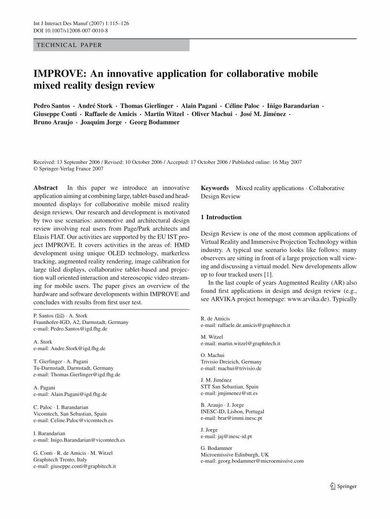
Fascinated by the potential of mobile collaborative AR,the architects strive for the following scenarios (Fig. 1):
1. The design of buildings begins with early shape studiesaiming at integrating the new building in its surroundingsand the landscape—the architects wish to see this stagesupported by sketching capabilities on the constructionsite using Tablet-PCs for early sketches and optical see-through glasses for visualising the sketch in its physicalenvironment.
2. Then, they want to take their sketch home into their officefor refinement. The result shall be reviewed collabora-tively and presented to customers in an indoor environ-ment using a couple of HMDs to support multiple userswith individual viewpoints. Pen-based direct 3D inter-action is envisaged for creating annotations and changeorders.
3. Finally, when everything is done, the architects want tobring the final design back to the physical constructionsite for a multiple user presentation. Again, many HMDsand large area tracking is needed. The correct lighting ofthe virtual model with respect to the lighting conditionsat the construction site is important.
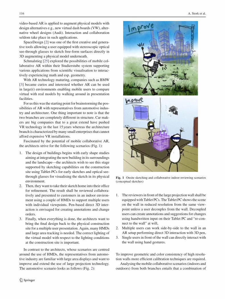
In contrast to the architects, whose scenarios are centredaround the use of HMDs, the representatives from automo-tive industry are familiar with large area displays and want toimprove and extend the use of large projection technology.The automotive scenario looks as follows (Fig. 2):
Fig. 1 Onsite sketching and collaborative indoor reviewing scenarios(conceptual sketches)
1. The reviewers in front of the large projection wall shall beequipped with Tablet PCs. The Tablet PC shows the sceneon the wall in reduced resolution from the same view-point unless a user decouples from the wall. Decoupledusers can create annotations and suggestions for changesusing handwritten input on their Tablet PC and “re-con-nect to the wall” at will,
2. Multiple users can work side-by-side to the wall in anAR setup performing direct 3D interaction with 3D pen,
3. Single users in front of the wall can directly interact withthe wall using hand gestures.
To improve geometric and color consistency of high resolu-tion walls more efficient calibration techniques are required.
Analysing the mobile collaborative scenarios (indoors andoutdoors) from both branches entails that a combination of
123
IMPROVE: An innovative application for collaborative mobile mixed reality design review 117
state-of-the art and progress in the following areas is neededto answer the requirements:
• Lightweight, power efficient stereoscopic opticalseethrough HMDs
• Large area multi user tracking,• Augmented reality rendering,• collaborative interaction techniques spanning display,
walls, Tablet PCs and direct 3D interaction,• Image calibration techniques,• Image (video) transmission techniques to ensure highest
possible rendering quality for mobile users using limitedcomputational and graphics power.
The authors are aware of no comparable approach that offersthat unique combination of technologies and techniques. Themost comparable work is probably done by Regenbrechtet al [26] while IMPROVE is wider in scope and spans morediverse environments and scenarios. IMPROVE not only con-tributes to the mixed and AR field with that combinationof techniques listed above but also with new achievementssuch as taylor-made organic light emitting display (OLEDs)by the consortium partner Micro Emissive Displays (MED),efficient image calibration techniques, innovative interactiontechniques, pre-computed radiance based rendering and opti-mized video transmission for mobile users.
The paper first introduces the system design chosen torealize the scenarios, then it presents the developments inthe various fields. The paper concludes with results fromfirst user test and a look into future developments.
2 System design
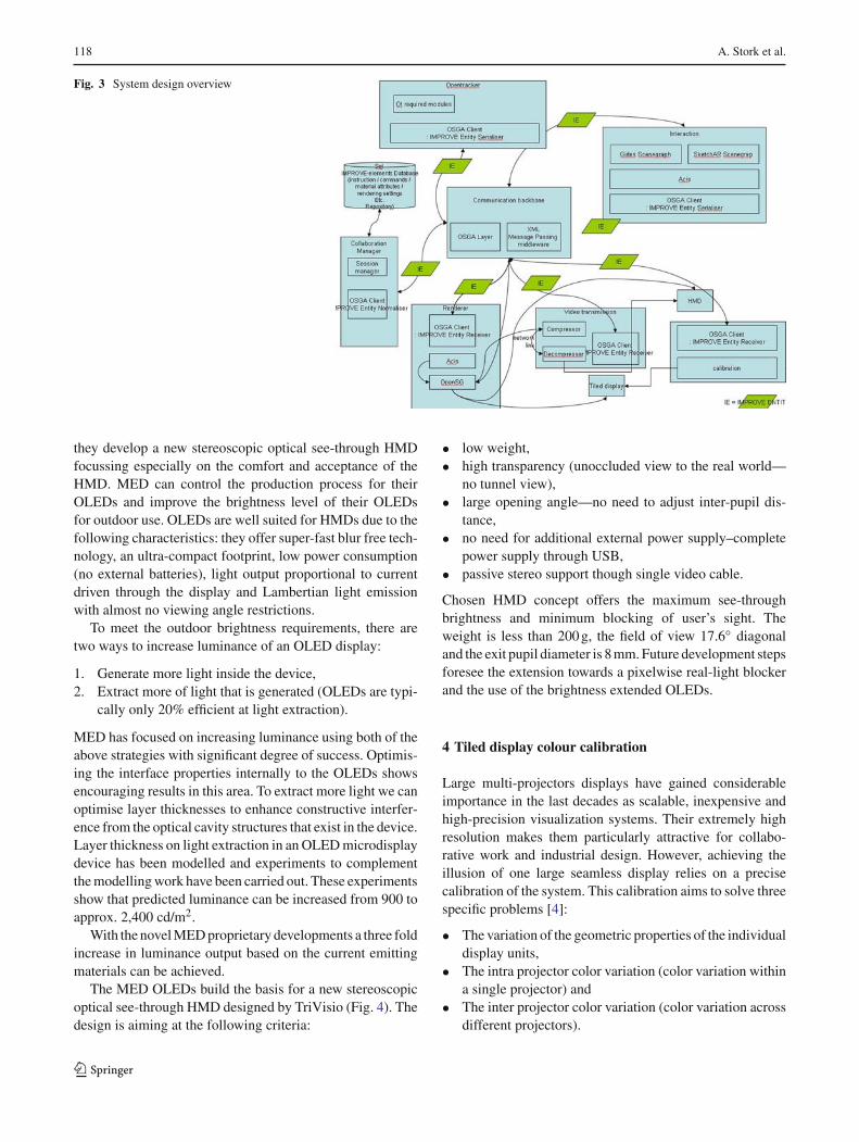
The IMPROVE system is build upon five distributed, auton-omous subsystems: Communication Backbone, Interaction,Tracking and Rendering Component and a Central Repos-itory. Each subsystem communicates with the other mod-ules through a high-level xml-based message exchange. Thischoice provides IMPROVE with a very high level of flexibil-ity in terms of physical distribution, ease of deployment androbustness. In fact since protocols are consistently definedeach component becomes both independent and replaceable.Further the number of IMPROVE clients can be scaled uparbitrarily if kept within the computational capacity of thechosen communication backbone server. The Communica-tion Backbone connects through XML messages to providethe required data exchange mechanisms. Messages can becategorized into modelling, annotation, configuration, cali-bration and shape data. Each software component registersto which data they are interested in by subscribing to variouschannel topics each defining a specific data set. The interac-tion component takes care of model/scene/session manage-ment, shape management, view management, annotations,design modifications, light creation and control and it
Fig. 2 Collaborative cAR design review scenario combining large andhead mounted displays (conceptual sketches)
follows a publisher/subscriber approach. Interactions can bedistinguished into two different kinds: the first is appliedlocally; the second is additionally transmitted via thecommunication backbone to the other components. Thetracking component sends the information captured by thedifferent devices supported and it wraps them into normal-ized XML messages called “IMPROVE Entities” (IE) andit sends this data via the client channel through the com-munication backbone. The rendering component visualizesthe virtual models and annotations using a variety of displaydevices. Finally the repository implements the functionalityto store and retrieve invoked commands and it stores con-figuration data like calibration, meta-information and setupdata (Fig. 3).
3 The OLED-based IMPROVE HMD
The IMPROVE consortium comprises the companies MED(the world record holder for the smallest display) and TriVisio(well known in the AR community for their HMDs). Together
123
118 A. Stork et al.
Fig. 3 System design overview
they develop a new stereoscopic optical see-through HMDfocussing especially on the comfort and acceptance of theHMD. MED can control the production process for theirOLEDs and improve the brightness level of their OLEDsfor outdoor use. OLEDs are well suited for HMDs due to thefollowing characteristics: they offer super-fast blur free tech-nology, an ultra-compact footprint, low power consumption(no external batteries), light output proportional to currentdriven through the display and Lambertian light emissionwith almost no viewing angle restrictions.
To meet the outdoor brightness requirements, there aretwo ways to increase luminance of an OLED display:
1. Generate more light inside the device,2. Extract more of light that is generated (OLEDs are typi-
cally only 20% efficient at light extraction).
MED has focused on increasing luminance using both of theabove strategies with significant degree of success. Optimis-ing the interface properties internally to the OLEDs showsencouraging results in this area. To extract more light we canoptimise layer thicknesses to enhance constructive interfer-ence from the optical cavity structures that exist in the device.Layer thickness on light extraction in an OLED microdisplaydevice has been modelled and experiments to complementthe modelling work have been carried out. These experimentsshow that predicted luminance can be increased from 900 toapprox. 2,400 cd/m2.
With the novel MED proprietary developments a three foldincrease in luminance output based on the current emittingmaterials can be achieved.
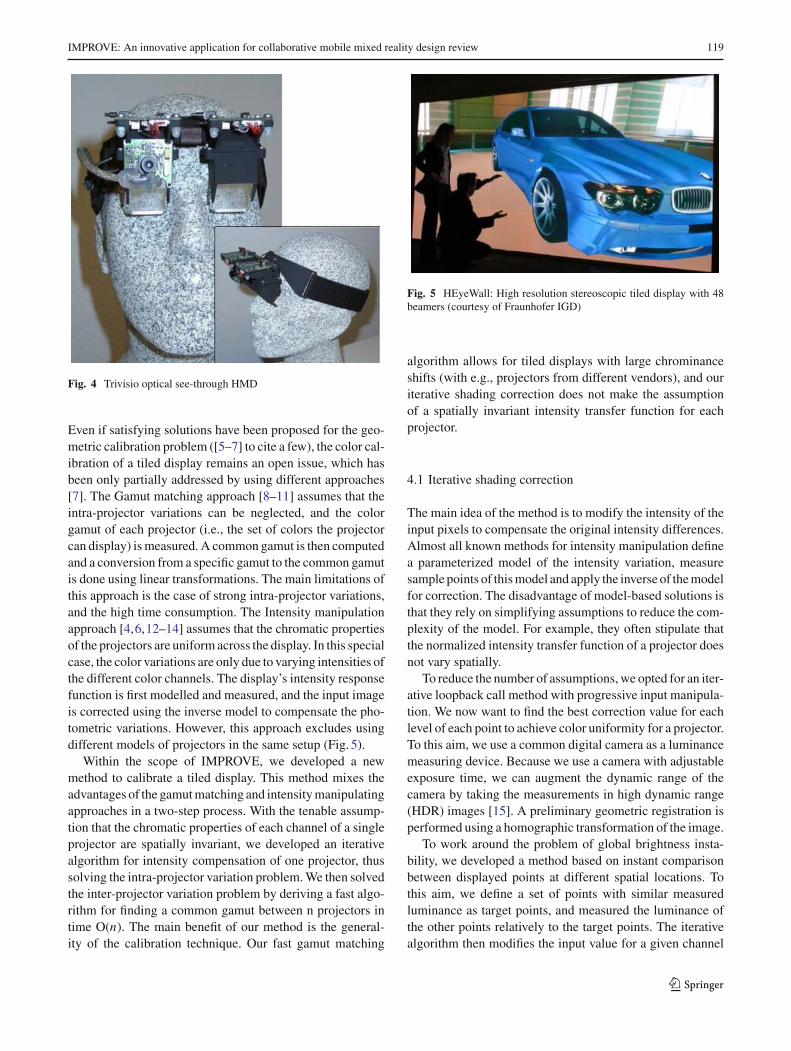
The MED OLEDs build the basis for a new stereoscopicoptical see-through HMD designed by TriVisio (Fig. 4). Thedesign is aiming at the following criteria:
• low weight,• high transparency (unoccluded view to the real world—
no tunnel view),• large opening angle—no need to adjust inter-pupil dis-
tance,• no need for additional external power supply–complete
power supply through USB,• passive stereo support though single video cable.
Chosen HMD concept offers the maximum see-throughbrightness and minimum blocking of user’s sight. Theweight is less than 200 g, the field of view 17.6◦ diagonaland the exit pupil diameter is 8 mm. Future development stepsforesee the extension towards a pixelwise real-light blockerand the use of the brightness extended OLEDs.
4 Tiled display colour calibration
Large multi-projectors displays have gained considerableimportance in the last decades as scalable, inexpensive andhigh-precision visualization systems. Their extremely highresolution makes them particularly attractive for collabo-rative work and industrial design. However, achieving theillusion of one large seamless display relies on a precisecalibration of the system. This calibration aims to solve threespecific problems [4]:
• The variation of the geometric properties of the individualdisplay units,
• The intra projector color variation (color variation withina single projector) and
• The inter projector color variation (color variation acrossdifferent projectors).
123
IMPROVE: An innovative application for collaborative mobile mixed reality design review 119
Fig. 4 Trivisio optical see-through HMD
Even if satisfying solutions have been proposed for the geo-metric calibration problem ([5–7] to cite a few), the color cal-ibration of a tiled display remains an open issue, which hasbeen only partially addressed by using different approaches[7]. The Gamut matching approach [8–11] assumes that theintra-projector variations can be neglected, and the colorgamut of each projector (i.e., the set of colors the projectorcan display) is measured. A common gamut is then computedand a conversion from a specific gamut to the common gamutis done using linear transformations. The main limitations ofthis approach is the case of strong intra-projector variations,and the high time consumption. The Intensity manipulationapproach [4,6,12–14] assumes that the chromatic propertiesof the projectors are uniform across the display. In this specialcase, the color variations are only due to varying intensities ofthe different color channels. The display’s intensity responsefunction is first modelled and measured, and the input imageis corrected using the inverse model to compensate the pho-tometric variations. However, this approach excludes usingdifferent models of projectors in the same setup (Fig. 5).
Within the scope of IMPROVE, we developed a newmethod to calibrate a tiled display. This method mixes theadvantages of the gamut matching and intensity manipulatingapproaches in a two-step process. With the tenable assump-tion that the chromatic properties of each channel of a singleprojector are spatially invariant, we developed an iterativealgorithm for intensity compensation of one projector, thussolving the intra-projector variation problem. We then solvedthe inter-projector variation problem by deriving a fast algo-rithm for finding a common gamut between n projectors intime O(n). The main benefit of our method is the general-ity of the calibration technique. Our fast gamut matching
Fig. 5 HEyeWall: High resolution stereoscopic tiled display with 48beamers (courtesy of Fraunhofer IGD)
algorithm allows for tiled displays with large chrominanceshifts (with e.g., projectors from different vendors), and ouriterative shading correction does not make the assumptionof a spatially invariant intensity transfer function for eachprojector.
4.1 Iterative shading correction
The main idea of the method is to modify the intensity of theinput pixels to compensate the original intensity differences.Almost all known methods for intensity manipulation definea parameterized model of the intensity variation, measuresample points of this model and apply the inverse of the modelfor correction. The disadvantage of model-based solutions isthat they rely on simplifying assumptions to reduce the com-plexity of the model. For example, they often stipulate thatthe normalized intensity transfer function of a projector doesnot vary spatially.
To reduce the number of assumptions, we opted for an iter-ative loopback call method with progressive input manipula-tion. We now want to find the best correction value for eachlevel of each point to achieve color uniformity for a projector.To this aim, we use a common digital camera as a luminancemeasuring device. Because we use a camera with adjustableexposure time, we can augment the dynamic range of thecamera by taking the measurements in high dynamic range(HDR) images [15]. A preliminary geometric registration isperformed using a homographic transformation of the image.
To work around the problem of global brightness insta-bility, we developed a method based on instant comparisonbetween displayed points at different spatial locations. Tothis aim, we define a set of points with similar measuredluminance as target points, and measured the luminance ofthe other points relatively to the target points. The iterativealgorithm then modifies the input value for a given channel
123
120 A. Stork et al.
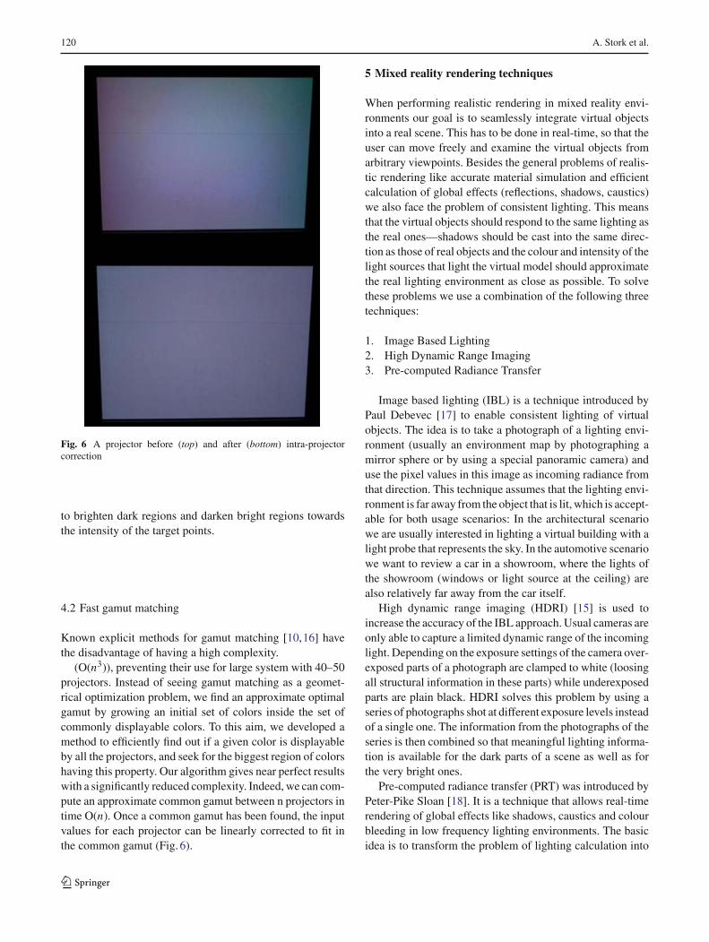
Fig. 6 A projector before (top) and after (bottom) intra-projectorcorrection
to brighten dark regions and darken bright regions towardsthe intensity of the target points.
4.2 Fast gamut matching
Known explicit methods for gamut matching [10,16] havethe disadvantage of having a high complexity.
(O(n3)), preventing their use for large system with 40–50projectors. Instead of seeing gamut matching as a geomet-rical optimization problem, we find an approximate optimalgamut by growing an initial set of colors inside the set ofcommonly displayable colors. To this aim, we developed amethod to efficiently find out if a given color is displayableby all the projectors, and seek for the biggest region of colorshaving this property. Our algorithm gives near perfect resultswith a significantly reduced complexity. Indeed, we can com-pute an approximate common gamut between n projectors intime O(n). Once a common gamut has been found, the inputvalues for each projector can be linearly corrected to fit inthe common gamut (Fig. 6).
5 Mixed reality rendering techniques
When performing realistic rendering in mixed reality envi-ronments our goal is to seamlessly integrate virtual objectsinto a real scene. This has to be done in real-time, so that theuser can move freely and examine the virtual objects fromarbitrary viewpoints. Besides the general problems of realis-tic rendering like accurate material simulation and efficientcalculation of global effects (reflections, shadows, caustics)we also face the problem of consistent lighting. This meansthat the virtual objects should respond to the same lighting asthe real ones—shadows should be cast into the same direc-tion as those of real objects and the colour and intensity of thelight sources that light the virtual model should approximatethe real lighting environment as close as possible. To solvethese problems we use a combination of the following threetechniques:
1. Image Based Lighting2. High Dynamic Range Imaging3. Pre-computed Radiance Transfer
Image based lighting (IBL) is a technique introduced byPaul Debevec [17] to enable consistent lighting of virtualobjects. The idea is to take a photograph of a lighting envi-ronment (usually an environment map by photographing amirror sphere or by using a special panoramic camera) anduse the pixel values in this image as incoming radiance fromthat direction. This technique assumes that the lighting envi-ronment is far away from the object that is lit, which is accept-able for both usage scenarios: In the architectural scenariowe are usually interested in lighting a virtual building with alight probe that represents the sky. In the automotive scenariowe want to review a car in a showroom, where the lights ofthe showroom (windows or light source at the ceiling) arealso relatively far away from the car itself.
High dynamic range imaging (HDRI) [15] is used toincrease the accuracy of the IBL approach. Usual cameras areonly able to capture a limited dynamic range of the incominglight. Depending on the exposure settings of the camera over-exposed parts of a photograph are clamped to white (loosingall structural information in these parts) while underexposedparts are plain black. HDRI solves this problem by using aseries of photographs shot at different exposure levels insteadof a single one. The information from the photographs of theseries is then combined so that meaningful lighting informa-tion is available for the dark parts of a scene as well as forthe very bright ones.
Pre-computed radiance transfer (PRT) was introduced byPeter-Pike Sloan [18]. It is a technique that allows real-timerendering of global effects like shadows, caustics and colourbleeding in low frequency lighting environments. The basicidea is to transform the problem of lighting calculation into
123
IMPROVE: An innovative application for collaborative mobile mixed reality design review 121
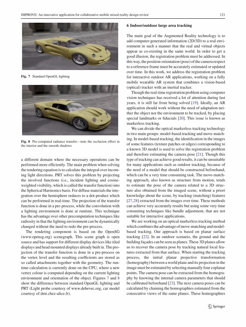
Fig. 7 Standard OpenGL lighting
Fig. 8 Pre-computed radiance transfer—note the occlusion effect inthe interior and the smooth shadows
a different domain where the necessary operations can beperformed more efficiently. The main problem when solvingthe rendering equation is to calculate the integral over incom-ing light directions. PRT solves this problem by projectingthe involved functions (i.e., incident lighting and cosine-weighted visibility, which is called the transfer function) intothe Spherical Harmonics basis. For diffuse materials the inte-gration over the hemisphere reduces to a dot-product whichcan be performed in real-time. The projection of the transferfunction is done in a pre-process, while the convolution witha lighting environment is done at runtime. This techniquehas the advantage over other precomputation techniques likeradiosity in that the lighting environment can be dynamicallychanged without the need to redo the pre-process.
The rendering component is based on the OpenSG(www.opensg.org) scenegraph. This scene graph is opensource and has support for different display devices like tileddisplays and head mounted displays already built in. The pro-jection of the transfer function is done in a pre-process onthe vertex level and the resulting coefficients are stored asso called attachments together with the geometry. The run-time calculation is currently done on the CPU, where a newvertex colour is computed depending on the current lightingenvironment and orientation of the object. Figures 7 and 8show the difference between standard OpenGL lighting andPRT (Light probe courtesy of www.debevec.org, car modelcourtesy of dmi.chez-alice.fr).
6 Indoor/outdoor large area tracking
The main goal of the Augmented Reality technology is toadd computer-generated information (2D/3D) to a real envi-ronment in such a manner that the real and virtual objectsappear as co-existing in the same world. In order to get agood illusion, the registration problem must be addressed. Inthis way, the position-orientation (pose) of the camera respectto a reference frame must be accurately estimated or updatedover time. In this work, we address the registration problemfor interactive outdoor AR applications, working on a fullymobile wearable AR system that combines a vision-based(optical) tracker with an inertial tracker.
Though the real-time registration problem using computervision techniques has received a lot of attention during lastyears, it is still far from being solved [19]. Ideally, an ARapplication should work without the need of adaptation nei-ther the object nor the environment to be tracked, by placingspecial landmarks or fiducials [20]. This issue is known asmarkerless tracking.
We can divide the optical markerless tracking technologyin two main groups: model-based tracking and move-match-ing. In model-based tracking, the identification in the imagesof some features (texture patches or edges) corresponding toa known 3D model is used to solve the registration problemand therefore estimating the camera pose [21]. Though thistype of tracking can achieve good results, it can be unsuitablefor many applications such as outdoor tracking, because ofthe need of a model that should be constructed beforehand,which can be a very time consuming task. The move-match-ing approach, also known as structure from motion, tendsto estimate the pose of the camera related to a 3D struc-ture also obtained from the imaged scene, without a prioriknowledge about the scene, by tracking (matching) features[27,28] extracted from the images over time. These methodscan achieve very accurately results but using some very timeconsuming techniques like bundle adjustment, that are notsuitable for interactive applications.
We are working on an optical markerless tracking methodwhich combines the advantage of move-matching and model-based tracking. Our approach is based on planar surfacetracking [22]. In an outdoor scenario, the ground and thebuilding façades can be seen as planes. These 3D planes allowus to recover the camera pose by tracking natural local fea-tures extracted from that surface. When starting the trackingprocess, the initial planar projective transformation(homography) between a world plane and its projection in theimage must be estimated by selecting manually four coplanarpoints. The camera pose can be extracted from the homogra-phy by knowing the internal camera parameters that shouldbe calibrated beforehand [23]. The next camera poses can becalculated by chaining the homographies estimated from theconsecutive views of the same planes. These homographies
123
122 A. Stork et al.
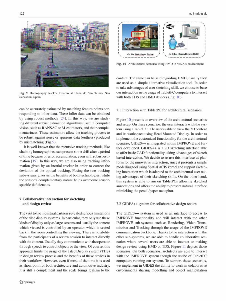
Fig. 9 Homography tracker test-run at Plaza de San Telmo, SanSebastian, Spain
can be accurately estimated by matching feature points cor-responding to inlier data. These inlier data can be obtainedby using robust methods [24]. In this way, we are study-ing different robust estimation algorithms used in computervision, such as RANSAC or M-estimators, and their comple-mentariness. These estimators allow the tracking process tobe robust against noise or spurious data (outliers) producedby mismatching (Fig. 9).
It is well known that the recursive tracking methods, likechaining homographies, can present some drift after a periodof time because of error accumulation, even with robust esti-mation [19]. In this way, we are also using tracking infor-mation given by an inertial tracker in order to correct thedeviation of the optical tracking. Fusing the two trackingsubsystems gives us the benefits of both technologies, whilethe sensor’s complementary nature helps overcome sensor-specific deficiencies.
7 Collaborative interaction for sketchingand design review
The visit to the industrial partners revealed serious limitationsof the tiled display systems. In particular, they only use thesekinds of display only as large screens and usually the contentwhich viewed is controlled by an operator which is seatedback in the room controlling the viewing. There is no abilityfrom the participants of a review session to interact directlywith the content. Usually they communicate with the operatorthrough speech to control objects or the view. Of course, thisapproach limits the usage of the Tiled Display system (TDS)in design review process and the benefits of these devices intheir workflow. However, even if most of the time it is usedas showroom for both architecture and automotive industry,it is still a complement and the scale brings realism to the
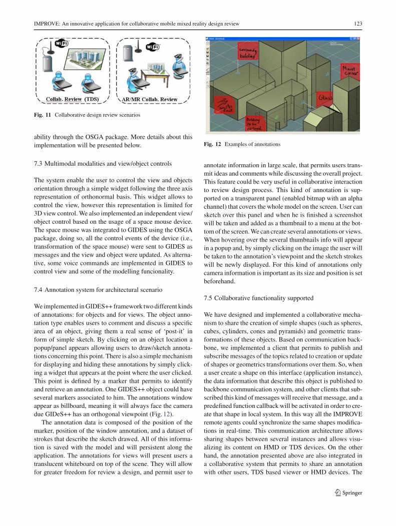
Fig. 10 Architectural scenario using HMD in VR/AR environment
content. The same can be said regarding HMD; usually theyare used as a simple alternative visualization tool. In orderto take advantages of user sketching skill, we choose to baseour interaction in the usage of TabletPC computers to interactwith both TDS and HMD devices (Fig. 10).
7.1 Interaction with TabletPC for architectural scenarios
Figure 10 presents an overview of the architectural scenariosand setup. On these scenarios, the user interacts with the sys-tem using a TabletPC. The user is able to view the 3D contentand its workspace using Head Mounted Display. In order toimplement the customized functionality for the architecturalscenario, GIDES++ is integrated within IMPROVE and fur-ther developed. GIDES++ is a 2D sketching interface ableto offer basic CAD functionality taking advantages of sketchbased interaction. We decide to re-use this interface as plat-form for the innovative interaction, since it presents a simplemodelling tool using Spatial ACIS kernel and support sketch-ing interaction which is adapted to the architectural user tak-ing advantages of their sketching skills. On the other hand,this system is able to run on TabletPCs allowing sketchedannotations and offers the ability to present natural interfacemimicking the pencil/paper metaphor.
7.2 GIDES++ system for collaborative design review
The GIDES++ system is used as an interface to access toIMPROVE functionality and will interact with the otherIMPROVE sub-systems such as Rendering, Video Trans-mission and Tracking through the usage of the IMPROVEcommunication backbone. Thanks to the interaction with theother sub-systems, we are able to handle collaborative sce-narios where several users are able to interact or makingdesign review using HMD or TDS. Figure 11 depicts thosescenarios. On both scenarios, architects are able to interactwith the IMPROVE system though the usabe of TabletPCcomputers running our system. To support these scenarios,we implement in GIDES the ability to work in colaborativeenvorinments sharing modelling and object manipulation
123
IMPROVE: An innovative application for collaborative mobile mixed reality design review 123
Fig. 11 Collaborative design review scenarios
ability through the OSGA package. More details about thisimplementation will be presented below.
7.3 Multimodal modalities and view/object controls
The system enable the user to control the view and objectsorientation through a simple widget following the three axisrepresentation of orthonormal basis. This widget allows tocontrol the view, however this representation is limited for3D view control. We also implemented an independent view/object control based on the usage of a space mouse device.The space mouse was integrated to GIDES using the OSGApackage, doing so, all the control events of the device (i.e.,transformation of the space mouse) were sent to GIDES asmessages and the view and object were updated. As alterna-tive, some voice commands are implemented in GIDES tocontrol view and some of the modelling funcionality.
7.4 Annotation system for architectural scenario
We implemented in GIDES++ framework two different kindsof annotations: for objects and for views. The object anno-tation type enables users to comment and discuss a specificarea of an object, giving them a real sense of ‘post-it’ inform of simple sketch. By clicking on an object location apopup/panel appears allowing users to draw/sketch annota-tions concerning this point. There is also a simple mechanismfor displaying and hiding these annotations by simply click-ing a widget that appears at the point where the user clicked.This point is defined by a marker that permits to identifyand retrieve an annotation. One GIDES++ object could haveseveral markers associated to him. The annotations windowappear as billboard, meaning it will always face the cameradue GIDeS++ has an orthogonal viewpoint (Fig. 12).
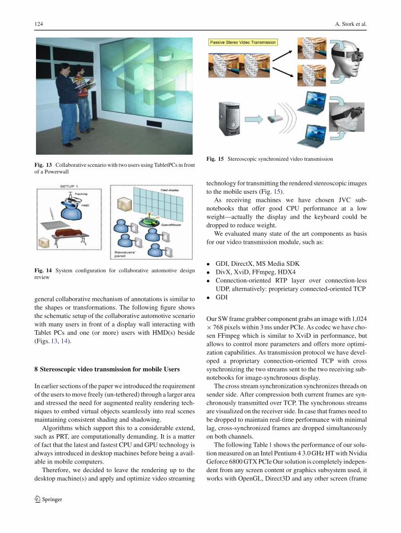
The annotation data is composed of the position of themarker, position of the window annotation, and a dataset ofstrokes that describe the sketch drawed. All of this informa-tion is saved with the model and will persistent along theapplication. The annotations for views will present users atranslucent whiteboard on top of the scene. They will allowfor greater freedom for review a design, and permit user to
Fig. 12 Examples of annotations
annotate information in large scale, that permits users trans-mit ideas and comments while discussing the overall project.This feature could be very useful in collaborative interactionto review design process. This kind of annotation is sup-ported on a transparent panel (enabled bitmap with an alphachannel) that covers the whole model on the screen. User cansketch over this panel and when he is finished a screenshotwill be taken and added as a thumbnail to a menu at the bot-tom of the screen. We can create several annotations or views.When hovering over the several thumbnails info will appearin a popup and, by simply clicking on the image the user willbe taken to the annotation’s viewpoint and the sketch strokeswill be newly displayed. For this kind of annotations onlycamera information is important as its size and position is setbeforehand.
7.5 Collaborative functionality supported
We have designed and implemented a collaborative mecha-nism to share the creation of simple shapes (such as spheres,cubes, cylinders, cones and pyramids) and geometric trans-formations of these objects. Based on communication back-bone, we implemented a client that permits to publish andsubscribe messages of the topics related to creation or updateof shapes or geometrics transformations over them. So, whena user create a shape on this interface (application instance),the data information that describe this object is published tobackbone communication system, and other clients that sub-scribed this kind of messages will receive that message, and apredefined function callback will be activated in order to cre-ate that shape in local system. In this way all the IMPROVEremote agents could synchronize the same shapes modifica-tions in real-time. This communication architecture allowssharing shapes between several instances and allows visu-alizing its content on HMD or TDS devices. On the otherhand, the annotation presented above are also integrated ina collaborative system that permits to share an annotationwith other users, TDS based viewer or HMD devices. The
123
124 A. Stork et al.
Fig. 13 Collaborative scenario with two users using TabletPCs in frontof a Powerwall
Fig. 14 System configuration for collaborative automotive designreview
general collaborative mechanism of annotations is similar tothe shapes or transformations. The following figure showsthe schematic setup of the collaborative automotive scenariowith many users in front of a display wall interacting withTablet PCs and one (or more) users with HMD(s) beside(Figs. 13, 14).
8 Stereoscopic video transmission for mobile Users
In earlier sections of the paper we introduced the requirementof the users to move freely (un-tethered) through a larger areaand stressed the need for augmented reality rendering tech-niques to embed virtual objects seamlessly into real scenesmaintaining consistent shading and shadowing.
Algorithms which support this to a considerable extend,such as PRT, are computationally demanding. It is a matterof fact that the latest and fastest CPU and GPU technology isalways introduced in desktop machines before being a avail-able in mobile computers.
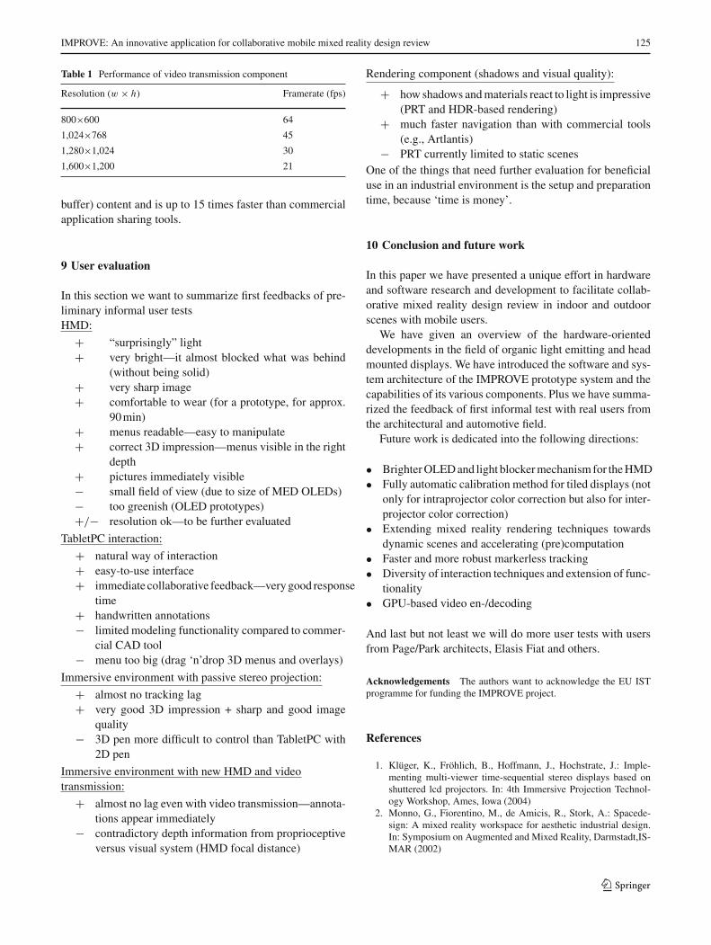
Therefore, we decided to leave the rendering up to thedesktop machine(s) and apply and optimize video streaming
Fig. 15 Stereoscopic synchronized video transmission
technology for transmitting the rendered stereoscopic imagesto the mobile users (Fig. 15).
As receiving machines we have chosen JVC sub-notebooks that offer good CPU performance at a lowweight—actually the display and the keyboard could bedropped to reduce weight.
We evaluated many state of the art components as basisfor our video transmission module, such as:
• GDI, DirectX, MS Media SDK• DivX, XviD, FFmpeg, HDX4• Connection-oriented RTP layer over connection-less
UDP, alternatively: proprietary connected-oriented TCP• GDI
Our SW frame grabber component grabs an image with 1,024× 768 pixels within 3 ms under PCIe. As codec we have cho-sen FFmpeg which is similar to XviD in performance, butallows to control more parameters and offers more optimi-zation capabilities. As transmission protocol we have devel-oped a proprietary connection-oriented TCP with crosssynchronizing the two streams sent to the two receiving sub-notebooks for image-synchronous display.
The cross stream synchronization synchronizes threads onsender side. After compression both current frames are syn-chronously transmitted over TCP. The synchronous streamsare visualized on the receiver side. In case that frames need tobe dropped to maintain real-time performance with minimallag, cross-synchronized frames are dropped simultaneouslyon both channels.
The following Table 1 shows the performance of our solu-tion measured on an Intel Pentium 4 3.0 GHz HT with NvidiaGeforce 6800 GTX PCIe Our solution is completely indepen-dent from any screen content or graphics subsystem used, itworks with OpenGL, Direct3D and any other screen (frame
123
IMPROVE: An innovative application for collaborative mobile mixed reality design review 125
Table 1 Performance of video transmission component
Resolution (w × h) Framerate (fps)
800×600 64
1,024×768 45
1,280×1,024 30
1,600×1,200 21
buffer) content and is up to 15 times faster than commercialapplication sharing tools.
9 User evaluation
In this section we want to summarize first feedbacks of pre-liminary informal user testsHMD:
+ “surprisingly” light+ very bright—it almost blocked what was behind
(without being solid)+ very sharp image+ comfortable to wear (for a prototype, for approx.
90 min)+ menus readable—easy to manipulate+ correct 3D impression—menus visible in the right
depth+ pictures immediately visible− small field of view (due to size of MED OLEDs)− too greenish (OLED prototypes)+/− resolution ok—to be further evaluated
TabletPC interaction:
+ natural way of interaction+ easy-to-use interface+ immediate collaborative feedback—very good response
time+ handwritten annotations− limited modeling functionality compared to commer-
cial CAD tool− menu too big (drag ‘n’drop 3D menus and overlays)
Immersive environment with passive stereo projection:
+ almost no tracking lag+ very good 3D impression + sharp and good image
quality− 3D pen more difficult to control than TabletPC with
2D pen
Immersive environment with new HMD and videotransmission:
+ almost no lag even with video transmission—annota-tions appear immediately
− contradictory depth information from proprioceptiveversus visual system (HMD focal distance)
Rendering component (shadows and visual quality):
+ how shadows and materials react to light is impressive(PRT and HDR-based rendering)
+ much faster navigation than with commercial tools(e.g., Artlantis)
− PRT currently limited to static scenesOne of the things that need further evaluation for beneficialuse in an industrial environment is the setup and preparationtime, because ‘time is money’.
10 Conclusion and future work
In this paper we have presented a unique effort in hardwareand software research and development to facilitate collab-orative mixed reality design review in indoor and outdoorscenes with mobile users.
We have given an overview of the hardware-orienteddevelopments in the field of organic light emitting and headmounted displays. We have introduced the software and sys-tem architecture of the IMPROVE prototype system and thecapabilities of its various components. Plus we have summa-rized the feedback of first informal test with real users fromthe architectural and automotive field.
Future work is dedicated into the following directions:
• Brighter OLED and light blocker mechanism for the HMD• Fully automatic calibration method for tiled displays (not
only for intraprojector color correction but also for inter-projector color correction)
• Extending mixed reality rendering techniques towardsdynamic scenes and accelerating (pre)computation
• Faster and more robust markerless tracking• Diversity of interaction techniques and extension of func-
tionality• GPU-based video en-/decoding
And last but not least we will do more user tests with usersfrom Page/Park architects, Elasis Fiat and others.
Acknowledgements The authors want to acknowledge the EU ISTprogramme for funding the IMPROVE project.
References
1. Klüger, K., Fröhlich, B., Hoffmann, J., Hochstrate, J.: Imple-menting multi-viewer time-sequential stereo displays based onshuttered lcd projectors. In: 4th Immersive Projection Technol-ogy Workshop, Ames, Iowa (2004)
2. Monno, G., Fiorentino, M., de Amicis, R., Stork, A.: Spacede-sign: A mixed reality workspace for aesthetic industrial design.In: Symposium on Augmented and Mixed Reality, Darmstadt,IS-MAR (2002)
123
126 A. Stork et al.
3. Klinker, G., Dutoit, A.H., Bauer, M., Bayer, J., Novak, V.,Matzke, D.: Fata Morgana—a presentation system for productdesign. In: International Symposium on Augmented and MixedReality, Darmstadt, ISMAR (2002)
4. Majumder, A., Stevens, R.: Color nonuniformity in projection-based displays: analysis and solutions. IEEE Trans. Vis. Comput.Graph. 10(2), 177–188 (2004)
5. Beardsley, P., Willwacher, T., Rao, S., Raskar, R., van Baar, J.,Forlines, C.: Ilamps: geometrically aware and selfconfiguring pro-jectors. In: Proceedings of ACM SIGGRAPH (2003)
6. Majumder, A., Towles, H., Raji, A., Gill, G., Fuchs, H.: Pixel-flex2: a comprehensive, automatic, casually-aligned multi-pro-jector display. In: IEEE Workshop on Projector-Camera Systems(PROCAMS) (2003)
7. Majumder, A., Brown, M., Yang, R.: Camera-Based CalibrationTechniques for Seamless Multi-Projector Displays, vol. 11 (2005)
8. Stone, M.C.: Color balancing experimental projection displays.In: Color Imaging Conference, pp. 342–347 (2001)
9. Stone M.C.: Color and brightness appearance issues in tiled dis-plays. IEEE Comput. Graph. Appl. 21(5), 58–66 (2001)
10. Chen, H., Wallace, G., Li, K.: Color gamut matching for tileddisplay walls. In: EGVE ’03: Proceedings of the Workshop onVirtual Environments, pp. 193–302 (2003)
11. Reiners, D., Kresse, W., Knoepfle, C.: Color consistency fordigital multi-projector stereo display systems: the heyewall andthe digital cave. In: EGVE’03: Proceedings of the Workshop onVirtual Environments 2003, pp. 271–279. ACM Press, Zurich,Switzerland (2003)
12. McCrory, M., Papka, M.E., Majumder, A., Jones, D., Stevens,R.: Using a camera to capture and correct spatial photomet-ric variation in multi-projector displays.In: IEEE Workshop onProjector-Camera Systems (PROCAMS) (2003)
13. Majumder, A., Stevens, R.: Perceptual photometric seamlessnessin projection-based tiled displays. ACM Trans. Graph. 24(1), 118–139 (2005)
14. Towles, H., Majumder, A., He, Z., Welch, G.: Achieving coloruniformity across multi-projector displays. In : IEEE ComputerSociety Press (ed.) VIS ’00 Proceedings of the Conference onVisualization ’00, pp. 117–124. Salt Lake City, Utah, United States(2000)
15. Debevec, P.E., Malik, J.: Recovering high dynamic range radiancemaps from photographs. Comput. Graph. 31, 369–378 (1997)
16. Bern, M., Eppstein, D.: Optimized color gamuts for tiled dis-plays. In: SCG ’03: Proceedings of the Nineteenth Annual Sym-posium on Computational Geometry, pp. 274–281. ACM Press,San Diego, California, USA (2003)
17. Debevec, P.: Rendering synthetic objects into real scenes: bridg-ing traditional and image-based graphics with global illuminationand high dynamic range photography. SIGGRAPH 98 (1998)
18. Kautz, J., Sloan, P.-P., Snyder, J.: Precomputed radiance transferfor real-time rendering in dynamic low-frequency lighting envi-ronments. SIGGRAPH (2002)
19. Lepetit, V., Fua, P.: Monocular Model-Based 3D Tracking of RigidObjects: A survey (2005)
20. Poupyrev, I., Ikamoto, I., Kato, H., Billinghurst, M., Tachibana,K.: Virtual object manipulation on tabletop ar environment. In:International Symposium on Augmented Reality, pp. 111–119(2000)
21. Drummond, T., Cipolla, R.: Real-time visual tracking of com-plex structures. IEEE Trans. Pattern Anal. Mach. Intell. 27, 932–946 (2002)
22. Fitzgibbon, A., Simon, G., Zisserman, A.: Markerless trackingusing planar structures in the scene. In: International Symposiumon Mixed and Augmented Reality, pp. 120–128 (2000)
23. Zhang, Z.: A flexible new technique for camera calibration. IEEETrans. Pattern Anal. Mach. Intell. 22, 1330–1334 (2000)
24. Stewart, C.V.: Robust parameter estimation. Soc. Ind. Appl. Math.41(3), 513–537 (1999)
25. Schmalstieg, D.: Designing immersive virtual reality for geometryeducation. IEEE Virtual Real. Alexandria, VA, USA (2006)
26. Regenbrecht, H., Wagner, M.: Interaction in a collaborative aug-mented reality enviromnment. In: Proceeding of Chi 2002, pp.504–505. ACM Press, Minneapolis, Minnesota, USA (2002)
27. Shi, J., Thomasi, C.: Good features to track. In: Conference onComputer Vision and Pattern Recognition (Seattle) (1994)
28. Lowe, D.: Distincitve image features from scale-invariant key-points. Int J Comput Vis. 20(2), 91–110 (2001)
123