IMPORTANT SAFETY INSTRUCTIONS - Parasound · · 2014-12-10IMPORTANT SAFETY INSTRUCTIONS The...
16
Transcript of IMPORTANT SAFETY INSTRUCTIONS - Parasound · · 2014-12-10IMPORTANT SAFETY INSTRUCTIONS The...


IMPORTANT SAFETY INSTRUCTIONS
The lightning flash with the arrowhead symbol within an equilateral triangle is intended to alert the user to the presence of “dangerous voltage” inside the product that may constitute a risk of electric shock.
The exclamation point within an equilateral triangle is intended to alert the user to the presence of important operating and maintenance instructions in the literature accompanying the product.
TO REDUCE THE RISK OF ELECTRIC SHOCK, DO NOT REMOVE COVER. NO USER-SERVICEABLE PARTS INSIDE. REFER SERVICING TO QUALIFIED SERVICE PERSONNEL
1. Read Instructions — Read all the safety and operating instructions before operating this product.
2. Retain Instructions — Retain safety and operating instructions for future reference.
3. Heed Warnings — Adhere to all warnings on the product and in the operating instructions.
4. Follow Instructions — Follow all operating and use instructions.
5. Cleaning — Unplug this product from the wall outlet before cleaning. Use a damp cloth for cleaning. Clean the outside of the product only.
6. Attachments — Do not use attachments that are not recommended by the product manufacturer; they may be hazardous.
7. Water and Moisture — Do not use this product near water.
8. Accessories — Do not place this product on an unstable cart or stand. The product may fall, causing bodily injury and damage to the product. A product and cart combination should be moved with care. Quick stops, excessive force, and uneven surfaces may cause the product and cart to overturn.
9. Ventilation — Slots and openings in the cabinet are provided for ventilation to ensure reliable opera-tion of the product and to protect it from overheating. These openings must not be blocked or covered. This product should not be placed in a built-in installation such as a bookcase or rack unless proper ventilation is provided.
10. Power Sources — Operate this product only from the type of power source indicated on the label. If you are not sure of the type of power supply to your home, consult your dealer or local power company. This product is equipped with a three-prong grounding plug. This plug will only fit into a grounding power outlet. If you are unable to insert the plug into the outlet, contact your electrician to replace your obsolete outlet. Do not defeat the safety purpose of the grounding plug.
11. Power Cord Protection — Power supply cords should be routed so that they are not likely to be walked on or pinched by items placed upon or against them.
12. Lightning — Unplug the unit from the wall outlet for added protection during a lightning storm and when it is left unattended and unused for long periods of time. This will prevent damage to the product due to lightning and power line surges.
13. Overloading — Do not overload wall outlets or extension cords. This can result in a fire or electric shock.
14. Inserting Objects into Unit — Never push objects of any kind into this product through any openings; they may touch dangerous voltage points or short out parts that could result in fire or electric shock.
15. Servicing — Do not attempt to repair or service this product yourself. Opening or removing covers may expose you to dangerous voltage and other hazards. Refer all servicing to qualified service personnel.
16. Damage Requiring Service — Unplug this product from the wall outlet and refer servicing to quali-fied service personnel under the following conditions: a) If the power-supply cord or plug is damaged. b) If liquid has been spilled into the product. c) If the product has been exposed to rain or water. d)If the product does not operate normally by following the operating instructions. e) If the product has been dropped or damaged in any way. f) If the product exhibits a distinct change in performance.
17. Replacement Parts — When replacement parts are required, be sure the service technician has used replacement parts specified by the manufacturer. Unauthorized substitutions may result in fire, electric shock, and other hazards.
19. Safety Check — Upon completion of any service or repairs to this product, ask the service technician to perform safety checks to determine that the product is in proper operating condition.
20. Wall or Ceiling Mounting — Mount the product to a wall or ceiling only as recommended.
21. Heat — The product should be situated away from heat sources such as radiators, heat registers, stoves, and other products (including amplifiers) that produce heat.
www.parasound.com

Introduction . . . . . . . . . . . . . . . . . . . . . . . . . . . . . . . . . . . . . . . . . . . . . . . . . . .Introduction . . . . . . . . . . . . . . . . . . . . . . . . . . . . . . . . . . . . . . . . . . . . . . . . . . .Introduction 2
115 – 230v AC Selector Switch . . . . . . . . . . . . . . . . . . . . . . . . . . . . . . . . . . . . . . .115 – 230v AC Selector Switch . . . . . . . . . . . . . . . . . . . . . . . . . . . . . . . . . . . . . . .115 – 230v AC Selector Switch 2
Ventilation Requirements . . . . . . . . . . . . . . . . . . . . . . . . . . . . . . . . . . . . . . . . . .Ventilation Requirements . . . . . . . . . . . . . . . . . . . . . . . . . . . . . . . . . . . . . . . . . .Ventilation Requirements 3
Rack Mounting . . . . . . . . . . . . . . . . . . . . . . . . . . . . . . . . . . . . . . . . . . . . . . . . .Rack Mounting . . . . . . . . . . . . . . . . . . . . . . . . . . . . . . . . . . . . . . . . . . . . . . . . .Rack Mounting 3
Rear Panel Connections and Controls . . . . . . . . . . . . . . . . . . . . . . . . . . . . . . . . . .Rear Panel Connections and Controls . . . . . . . . . . . . . . . . . . . . . . . . . . . . . . . . . .Rear Panel Connections and Controls 4
Front Panel Controls and Indicators . . . . . . . . . . . . . . . . . . . . . . . . . . . . . . . . . . . .Front Panel Controls and Indicators . . . . . . . . . . . . . . . . . . . . . . . . . . . . . . . . . . . .Front Panel Controls and Indicators 7
Remote Control Handset . . . . . . . . . . . . . . . . . . . . . . . . . . . . . . . . . . . . . . . . . . .Remote Control Handset . . . . . . . . . . . . . . . . . . . . . . . . . . . . . . . . . . . . . . . . . . .Remote Control Handset 8
Typical Problems and Remedies . . . . . . . . . . . . . . . . . . . . . . . . . . . . . . . . . . . . . .Typical Problems and Remedies . . . . . . . . . . . . . . . . . . . . . . . . . . . . . . . . . . . . . .Typical Problems and Remedies 9
If You Require Assistance . . . . . . . . . . . . . . . . . . . . . . . . . . . . . . . . . . . . . . . . . .If You Require Assistance . . . . . . . . . . . . . . . . . . . . . . . . . . . . . . . . . . . . . . . . . .If You Require Assistance 9
Warranty Repair . . . . . . . . . . . . . . . . . . . . . . . . . . . . . . . . . . . . . . . . . . . . . . . .Warranty Repair . . . . . . . . . . . . . . . . . . . . . . . . . . . . . . . . . . . . . . . . . . . . . . . .Warranty Repair 9
Specifications . . . . . . . . . . . . . . . . . . . . . . . . . . . . . . . . . . . . . . . . . . . . . . . . .Specifications . . . . . . . . . . . . . . . . . . . . . . . . . . . . . . . . . . . . . . . . . . . . . . . . .Specifications 10
TABLE OF CONTENTS 1
Thank You for Choosing ParasoundCongratulations and thank you for your purchase of this precision Parasound audio component.
The Parasound Zpre2 Preamplifier is the second generation of one of the world’s most
popular and proven preamplifiers. It has been designed for a wide variety of applications,
including multi-room, multi-zone installations, desktop audio, PC-Mac audio, bedroom or den
systems. The versatility of the Zpre2 allows many connection and configuration options,
so please be sure to read this manual thoroughly before you begin installation.
UnpackingCarefully unpack your Zpre2 and these accessories:
• Detachable AC power cord• Remote control handset with two AAA batteries• Two trigger wires, one with 2.5 mm sub-mini plugs, one with a 2.5mm and a 3.5mm mini plug
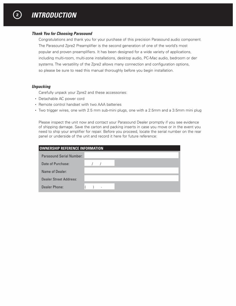
Please inspect the unit now and contact your Parasound Dealer promptly if you see evidence of shipping damage. Save the carton and packing inserts in case you move or in the event you need to ship your amplifier for repair. Before you proceed, locate the serial number on the rear panel or underside of the unit and record it here for future reference:
INTRODUCTION
OWNERSHIP REFERENCE INFORMATION
Parasound Serial Number:
Date of Purchase: / / / /
Name of Dealer:
Dealer Street Address:
Dealer Phone: ( ) - ( ) -
2

AC VOLTAGE, INSTALLATION, AND RACK MOUNTING
115v - 230v AC Voltage Selector Switch This switch is found on the chassis bottom. The 115V position of this switch is correct for North America; most other countries require setting it to 230V. Make sure the 115/230V switch is set for the correct AC line (mains) voltage before you connect the Zpre2’s power cord and before you install it. The unit may be seriously damaged if this switch is set incorrectly.
230
AC Voltage S Voltage S V elector Switch.Shown set for 230v.
Installation and Ventilation RequirementsInstall your Zpre2 away from heat sources such as heating ducts, radiators, or other heat producing components. Always position the Zpre2 horizontally.
Observe the following ventilation guidelines when installing the Zpre2 in an equipment rack or any other enclosed space:
We recommend that you place the Zpre2 beneath, rather than above, a power amplifier. Do not install the Zpre2 in an unventilated equipment cabinet or compartment. Pockets of heat can build up even in cabinets with open front and back sides. Therefore, a ventilation fan is highly recommended.
Rack MountingThe Zpre2 occupies only half the width of a single rack space in a standard 19" equipment rack. For rack mounting, you can fasten it to another Parasound Z Custom model by using the Parasound SBS (Side-by-Side) mounting kit. You can also mount a single Zpre2 in the rack with the accessory Zblank panel. The SBS includes four rack mount bolts plus four pairs of plastic “shoulder washers.” The washers are important because they insulate the Zpre2 front panel (and chassis) from the metal equipment rack and from the four mounting bolts. Locate these washers on both sides of the front panel before the mounting bolts are screwed into the rack rail.
Zpre2 SBS Zblank panelBehind Panels
3

REAR PANEL CONNECTIONS AND CONTROLS
Connection PrecautionsDisconnect the AC cord before making or changing any input, output or trigger wire connections.
Make sure there is no strain or tension on any wires that could cause them to pull loose.
AC Voltage Selector On Bottoms, o, C Preamp 12V Trigger
Audio In JacksThe Zpre2 has input jacks for up to four audio sources. These are identical line level inputs, however the In 1-Priority jacks have a special automatic select function which will affect which source you decide to connect to them. See Remote Control, Priority Input Switching to help you make this decision.
AC Voltage Selector On BottomParasound Products, Inc. San Francisco, CA USA ZPre2 Zone Preamplifier
1 - Priori Fixed-Rec Vari
Audio Out 1 Video In 2 Video Out
Video In JacksThe Zpre2 has input jacks to accommodate up to four composite video sources. The video inputs correspond to the same numbered audio input and are switched at the same time.
Audio Out JacksMain - Variable Out jacks connect to your power amplifier. Their output level is controlled by the Zpre2 volume control.
Fixed – Rec Out jacks feed a recorder or system controller for which a fixed output level is prefer-able. The signal at the Fixed - Rec output jacks does not vary as the volume control is adjusted.
Video Output Jacks The Video Out jack feeds your TV or video monitor.
The Rec Out jack feeds your video recorder. In fact, these jacks carry the same video signal and you may certainly use the Rec Out jack to connect a second video display.
4

REAR PANEL CONNECTIONS AND CONTROLS continued
Zone 1 2 3 4 SwitchYou can ignore this switch if you are using a single Zpre2 in your system.
The Zone switch and remote control handset can select four discrete IR codes to control up to four Zpre2s in four zones independently with a single remote handset or IR-based system controller.
The Zone switch and remote handset factory default settings are both 1. If you move the Zone switch to another number you’ll also have to reprogram the remote handset with the same zone number (see Remote Control).
Note: The Zone switch selects a new IR zone code only when the Zpre2 is turned off. If you Note: The Zone switch selects a new IR zone code only when the Zpre2 is turned off. If you Note:move the Zone switch to select a new IR zone code while the Zpre2 is turned on, you’ll need to turn it off for a few seconds, then on again.
Ext (External) Remote Jack Your Zpre2 accepts the infrared signal of any popular infrared repeater system to facilitate remote control operation from another room or when it is installed within a closed cabinet. This connector is a 1/8” (3.5 mm) two conductor mini jack; its center conductor (plug tip) is +, its outer conductor (plug sleeve) is – .
Note: Unlike Parasound Surround Controllers, the Zpre2 Ext Remote input does not require an Note: Unlike Parasound Surround Controllers, the Zpre2 Ext Remote input does not require an Note:amplified IR connecting block.
Automatic Turn On OptionsFor convenience the Zpre2 can be triggered to turn on automatically when a suitable voltage is applied to its 12V In (input) jack. When automatic turn on is selected the Zpre2 front panel Power button is disabled so that on/off is determined solely by the triggering system master controller.
RS-232 Control JackThis is a DB9 serial port which accepts commands from your system controller (“write”) and feeds back status to be displayed (“read”). The following can be controlled and displayed:
- Power on
- Input selected
- Volume was adjusted via RS-232
- Mute on
Note: The RS-232 will feedback when volume level is changed by the RS-232, but not if it is Note: The RS-232 will feedback when volume level is changed by the RS-232, but not if it is Note:adjusted with the front panel knob or remote control handset. The RS-232 “read” does not display the actual level because it uses an analog volume control which cannot show its setting. In most instances this won’t be an issue, since volume level is immediately heard as satisfactory, too high or too low.
“Write” and “Read” RS-232 codes for the Zpre2 are available at our website, www.parasound.com.
Auto - Man (Manual) Turn On SwitchAuto position
When the Auto - Man switch is set to its Auto position, the Zpre2 is turned on and off with an external +9 V to + 12 V voltage from your controller or preamplifier. When the external voltage ceases the Zpre2 will turn off immediately.
Note: The Auto switch position disables the front panel Power button.Note: The Auto switch position disables the front panel Power button.Note:
Man Position
When the Auto - Man switch is in its Man (manual) position, the auto turn on function is disabled and the Zpre2 must be turned on and off manually with the Power button on its front panel or its remote control.
Auto On
R
L
RS-232 Control
In
1 2 3 4
Auto Man
115V/230V 60Hz/50Hz 20W
0.5A Fuse Only
AC Voltage Selector On BottomParasound Products, Inc. San Francisco, CA USA
Ext Remote Zone
ZPre2 Zone Preamplifier
1 - Priority Fixed-Rec Variable-Main Rec Out432 3 4
Audio In Audio Out 1 Video In 2 Video Out
12V TriggerOut
5

REAR PANEL CONNECTIONS AND CONTROLS continued
12V Trigger Jacks
In Trigger JackThe Zpre2 12V input uses a 2.5 mm sub-mini jack. To trigger the Zpre2, plug one end of the provided cord into this jack and the other end into the source component’s trigger output. Some components, including Parasound Surround Controllers, use 3.5 mm trigger output jacks, so we have also included a trigger wire with 2.5mm and a 3.5mm mini plugs. If the control component’s trigger output is a + and - terminal, you can cut the 2.5 mm plug off one end of the included trigger wire and attach the bare wires to these terminals. The lead with the white stripe on it corresponds to the plug’s tip and the unmarked lead cor-responds to the sleeve of the plug.
Note: If the trigger voltage source is DC, the trigger plug tip must be + (positive) : If the trigger voltage source is DC, the trigger plug tip must be + (positive) :and its sleeve – (negative). The Zpre2 trigger current draw is a negligible 15 mA.
Out Trigger JackThis jack is live whenever the Zpre2 is turned on. This enables the Zpre2 to turn a companion amplifier (or other component) on and off automatically. The triggered component must be equipped with a 12V trigger circuit. Connect the Zpre2 12V output jack to the triggered component’s trigger input jack using the provided trigger wire with the 2.5 mm sub-mini plugs.
Note: Most Parasound Power Amplifiers use a 2.5mm 12V trigger input jack.: Most Parasound Power Amplifiers use a 2.5mm 12V trigger input jack.:
If the triggered component’s trigger input is a + and - terminal, as in earlier Parasound Power Amplifier models, you can cut the 2.5 mm plug off one end of this trigger wire and attach the bare wires to the input terminals. The lead with the white stripe on it corresponds to the plug’s tip and the unmarked lead corresponds to the sleeve of the plug.
Note: The trigger voltage source is DC and the trigger plug tip is + (positive) and Note: The trigger voltage source is DC and the trigger plug tip is + (positive) and Note:its sleeve – (negative). The Zpre2 trigger output maximum current capability is 150 mA.
AC Power Connections and AC GroundingIf possible, plug your Zpre2 into the same AC outlet that your accompanying audio components (particularly your source components and power amplifier) are plugged into. The ground potential between different AC outlets may be higher or lower, resulting in audible hum.
Auto On
R
L
RS-232 Control
In
1 2 3 4
Auto Man
115V/230V 60Hz/50Hz 20W
0.5A Fuse Only
AC Voltage Selector On BottomParasound Products, Inc. San Francisco, CA USA
Ext Remote Zone
ZPre2 Zone Preamplifier
1 - Priority Fixed-Rec Variable-Main Rec Out432 3 4
Audio In Audio Out 1 Video In 2 Video Out
12V TriggerOut
6

FRONT PANEL CONTROLS AND DISPLAY
Power ButtonPress the Power button once to turn the Zpre2 on, press it again to turn it off.
Note: The Power button is inoperative when the rear panel Auto On switch is set to Auto.Note: The Power button is inoperative when the rear panel Auto On switch is set to Auto.Note:
(Headphone) JackThe headphone jack accepts a 1/8” (3.5 mm) mini plug. The Main audio out is muted when the headphone plug inserts into this jack, but the output to the Fixed – Rec jacks remains live.
Bass and Treble Knobs These control tone. Maximum boost and cut is 10dB for each control. At their center mid-point you will feel a click-stop. At this point there is no cut or boost and frequency response is flat.
Input KnobThe input knob selects input sources. Audio and Video inputs are selected together.
Balance KnobThis adjusts the relative volume of the left and right channels. In its center position the channel levels are the same.
Level KnobThe Level knob adjusts listening level. Because it is motor-driven for remote control operation, you will notice some resistance when turning it by hand.
Display IndicatorsInputs 1 2 3 4 – Indicates the selected audio and video inputs.
1 – green: In 1 is selected, priority auto select function not engaged.
1 – orange: Priority auto select function enabled and Input 1 was selected manually or automati-cally by an audio signal.
1 – red: Priority auto select function enabled and another input is selected. After priority auto select is enabled 1 will only appear red if no audio signal is present at the Audio In 1 jacks.
Mute – red: Lights when the main audio output is muted.
Zone – green: Flashes green when the Zpre2 accepts a command from the remote handset.
Zone – red: Flashes red when the Zpre2 rejects a command from the remote handset because
the remote and the Zpre2 IR zone codes are different.
7

REMOTE CONTROL FUNCTIONS
The PTZ-1 remote control has a range of approximately 20 - 25 feet (6 - 7.5 meters). Use only AAA alkaline batteries in the handset and insert them according to the + and – polarity markings in the battery compartment. The PTZ-1 Off, On, Mute Volume, In 1-4 buttons, Zpre2 Pre Set and Z 1-4 IR Zone # buttons are for the Zpre2. The tuner buttons control the matching Parasound Ztuner.
On and Off ButtonsThese have the same function as the Power button on the front panel.
Press On to turn the Zpre2 on. The display will illuminate.
Press Off to turn the Zpre2 off.
These separate buttons enable programming unambiguous “hard” off and on commands into a system controller or to create a macro sequence for a learning-type remote control.
Note: These buttons will not function when the rear panel Note: These buttons will not function when the rear panel Note:Auto-Man switch is set to Auto.
Mute ButtonPressing the Mute button once mutes the signal at the Main Out jacks and Mute will glow red in the display. It does not mute the signal at the Fixed level out jacks or the headphone jack. Press the Mute button a second time to cancel mute.
Volume ^ / v ButtonsThese buttons control the rotation of the front panel motorized Level knob, to increase and decrease listening volume levels.
Preamp Input ButtonsThe primary purpose of the four buttons just below Preamp, 1/Priority, 2, 3, 4, is to select the Audio and Video source inputs 1-4.
Note: Preamp buttons 5-7 do not function with the Zpre2. Note: Preamp buttons 5-7 do not function with the Zpre2. Note:
Preamp 1 / Priority Auto Select ButtonYou can program the Zpre2 to automatically select Audio and Video Inputs 1 when an audio signal is present at the Audio In 1 jacks. With this priority, Preamp Input 1 will override inputs 2, 3, or 4, even if one of them was already selected.
To enable the Input 1 / Priority auto select function, press and hold the Preamp 1 button for about 3-4 seconds until the Input 1 indicator changes from green to red or orange.
1 Indicator Function
Green Priority auto select is not engaged and In 1 is selected manually.
Orange Priority auto select is enabled and In I is selected manually.
Orange Priority for In 1 is enabled and In 1 is selected automatically because an audio signal is present.
Red Priority auto select for In 1 is enabled and another input is selected.
Red Priority auto select for In 1 is enabled, but no audio signal is present at the Audio 1 In jacks.
Note: After the Audio In 1 source stops playing the In 1 indicator will remain orange until you Note: After the Audio In 1 source stops playing the In 1 indicator will remain orange until you Note:select another input manually. You can select another input when the 1 indicator is green or red. If 1 glows orange you can select another input only if no audio signal is present or if you disen-gage the Priority auto select. To disable Input 1 Priority auto select press and hold the Preamp 1 button for about 3-4 seconds until the 1 indicator glows green.
8

REMOTE CONTROL FUNCTIONS continued
With this handy feature the Zpre2 will automatically switch to your favorite source component whenever it’s playing. If you use the Zpre2 to control a DVD player, tuner and satellite receiver in your bedroom, you can connect its Audio In 1 jacks to the feed from a distant main system controller. Its program will be selected automatically when it’s playing.
Pre Set ButtonThe Pre Set button is used only for reprogramming the remote handset IR zone code. You don’t have to worry about this button if you only have a single Zpre2 in your system. If your Zpre2 is not responding to the remote, please read the following information.
IR Zone Code NumbersThe remote handset will not operate the Zpre2 unless its IR zone code number matches the Zpre2 Zone switch setting (and the front panel Zone flashes green). The factory settings for the remote handset and the unit’s Zone switch are both 1. If you change the Zone switch on the Zpre2 to a new number you’ll also need to change the remote handset IR zone code to the same number.
Programming a new IR Zone Code NumberTo reprogram the remote press you must press two buttons at the same time; press both the Zpre2 Pre Set button and the desired IR Zone # button for a few seconds. When the new IR zone code is successfully programmed Zone will flash green when you press any remote button. Zone will flash red if the new IR zone code wasn’t successfully programmed.
Maintaining Your Zpre2Your Parasound Zpre2 Preamplifier requires no periodic maintenance other than an occasional admiring glance. It has no user-serviceable parts inside. To avoid the risk of electric shock, do not remove its top cover. The exterior can be cleaned with a soft cloth pre-moistened only with a few drops of water or glass cleaner.
9

ARE YOU HAVING DIFFICULTY?
No sound
- Check that AC is live.
- Check that input and output cables are secure at both ends.
- Make sure it is switched to the correct input.
- Is the unit on? Check setting of the Auto-Man switch.
Remote does not operate
- Zpre2 won’t respond to the remote control. Press remote’s Zone button then remote’s 1 button.
- Weak or dead batteries in remote. Replace batteries and please recycle old ones.
- IR Interference. Insure that the front panel IR receiver is not obscured or exposed to direct sunlight or to an LCD or a plasma TV screen.
- If you can not select an input other than Input 1, turn off the Priority auto select feature by holding the Preamp In 1 button down for 4 seconds (see page 8).
- IR zone code setting does not match the unit. Change zone numbers so they match.
- Incorrect remote. Must be Parasound PTZ-1 or using IR codes corresponding to PTZ-1.
Background Hum
- Move audio cables and AC cords away from each other.
- Try different routes for the audio cables and AC cords.
- Make sure insulating shoulder washers are used if unit is rack mounted.
- Try reversing the direction of the AC plugs in other components, one by one.
Distorted and Weak Sound
- Make sure the gain of the power amp is not set too low.
- Are you trying to use Zpre2 with a turntable? It does not have a built-in phono preamplifier stage. You will need a phono preamp such as the matching Parasound Zphono.
10

Call your Parasound dealer first. If the dealer can’t help you with your problem we encourage you to call Parasound’s Technical Service Department, toll-free at 1-866-770-8324, Monday - Friday, 8am - 4pm Pacific time. We can suggest other diagnostic tests you can easily perform. If we determine that your Zpre2 should be returned to Parasound or an Authorized Parasound Warranty Center for inspection and possible servicing, we will provide the location of a warranty center near you or shipping instructions for the unit’s return to Parasound.
Before You Return Any Unit to Parasound for ServiceBefore you send your unit to Parasound, you will need to obtain a specific Return Authorization (RA) number and shipping instructions from Parasound’s Technical Department. The RA num-ber must be clearly marked on the outer carton. Use the original factory packing materials and arrange adequate insurance to cover its value. You must include a copy of your purchase receipt, since this document establishes the validity of this unit’s warranty. Warranty repairs are only performed by Parasound or Parasound Authorized warranty centers when your purchase receipt is from a Parasound Authorized Dealer or Parasound Authorized Reseller.
Units Will Be Refused by Parasound Under the Following Conditions:
1. Unit was sent without the Parasound-assigned RA number marked on the carton.
2. Unit was sent in an unsuitable shipping carton, likely to have been damaged in transit.
3. Unit has inadequate packing, unit likely to have been damaged in transit.
4. Unit was shipped collect for shipping charges. We do not accept collect shipments.
5. Unit was shipped via the US Postal Service.
6. Unit was sent to an address other than the address instructed by our Technical Department.
Note: The shipping address is not the same as Parasound’s office address.
Warranty RepairRead your accompanying Parasound Limited Warranty carefully to understand the applicable rights and limitations. This section provides instructions for obtaining repairs, both for units covered under the Parasound Limited Warranty and for units or situations which are outside the Warranty.
Unit is not eligible for repair under the terms of the Parasound warranty if:
1. Unit was not purchased from a Parasound Authorized Dealer or Parasound Authorized Reseller.
2. You are not the original owner. The Parasound warranty is not transferable.
3. Unit’s serial number was removed, modified, or defaced.
4. Unit shows evidence of abuse and/or misuse.
5. Unit was modified in any way.
6. A prior repair was attempted by an unauthorized repair station.
WARRANTY REPAIR 11

PARASOUND ZPRE2 SPECIFICATIONS
Frequency Response – Audio10 Hz - 100 kHz, +0/-3 dB
10 Hz - 50 kHz, +0/-0.8 dB
Frequency Bandwidth – Composite Video10 MHz
Total Harmonic Distortion0.006%
S/N Ratio112 dB, input shorted, IHF A-weighted
92 dB, input shorted, unweighted
Input Impedance15 k Ω
Input Sensitivity150 mV for 1 V output
Maximum Output: 7.6 V
Crosstalk83 dB at 1 kHz
76 dB at 20 kHz
Tone ControlsBass +/- 8 dB at 100 Hz
Treble +/- 10 dB at 10 kHz
AC Power Requirement110 - 120 V / 220 -240 V, 50 - 60 Hz
2 watt standby; 20 watts when turned on
Dimensions91⁄1⁄12⁄2⁄ ” Wide
10” Deep with connectors
2” High with feet, 13⁄3⁄34⁄4⁄ ” panel only
241 x 254 x 50mm, 44.1mm panel only
Net Weight4.6 lbs, 2.1 kg
Rack Mount AccessoryMay be Purchased Separately
SBS: Bracket and bolts to attach any two Z Custom units side-by-side in a standard 19” equipment rack.
Zblank: 91⁄1⁄12⁄2⁄ ” x 13⁄3⁄34⁄4⁄ ” blank panel, required
to mount a single Zpre2 unit; Zblank kit includes one SBS.
Specifications and features subject to change or improvement without notice.
12

NOTES
Notes:
13

Rev 0.92 © Parasound Products, Inc. 2005