Important notes before you get started
83
Tel: 519-343-2335 Toll Free: 1-866-838-6729 Fax: 519-343-2399 P.O. Box #1125 King St. Palmerston, ON N0G2P0 Even more detailed info & videos online! → http://multisheltersolutions.com/our-structure-options- coverings/installation-guide/ Important notes before you get started If there is anything you do not understand in this installation guide, do not hesitate to call before you start, this could affect your warranty.
Transcript of Important notes before you get started

Tel: 519-343-2335 Toll Free: 1-866-838-6729 Fax: 519-343-2399
P.O. Box #1125 King St. Palmerston, ON N0G2P0
Even more detailed info & videos online! → http://multisheltersolutions.com/our-structure-options-
coverings/installation-guide/
Important notes before you get started
If there is anything you do not understand in this installation guide,
do not hesitate to call before you start,
this could affect your warranty.

MSS is only responsible for the replacement of any defective material. This warranty does not cover labour, freight costs, disposal expenses, improper installation, improperly maintained structures, unpaid structures, damage under “Acts of God” (violent winds/tornadoes, heavy snows, etc.), or faulty product samples not returned within 30 days.
You have 30 days to report shortages
or the order is considered complete
If there are any parts with damage, they must be reported prior to assembly.
MSS endeavors to check our products prior to
delivery; however, customers are encouraged to inspect
their product as soon as possible as most manufacturing flaws are evident immediately.
There are no special tools required for assembly. Drills (either corded or cordless) should run between 1000 and 1500 r.p.m. A movable platform or scaffold equal to 75% of the peak height is suggested for safety considerations and convenience of working PLEASE NOTE: Any italicized words in this document are
words that are listed in the glossary.
We don’t sell you a shelter…We help you buy one!


If you are reading this and haven’t purchased a structure, here are some points to consider
1. Pick a Location: Your building must be level from side to side. If you can’t excavate, we can design a variation. End to end slope is ok but if it is more than 1%, we need to know. If you are butting against a building, there may need to be some extra hoops in the first 12’ of length. Building behind something does not provide shelter. You actually increase wind turbulence. 2. Pick a width: Most of our standard widths can easily be modified if it needs to be specific. The widest we do with engineered drawings is 30’ but have supplied up to 36’ wide. 3. Pick a length: Any length is possible; simply by adding hoops If you are building between 2 fixed points, the last hoop spacing can be modified to fit the spot. 4. Pick a height: We have 7 lengths of steel to pick from and do not bend anything until we get an order. Building higher will improve the snow shedding characteristics of the building. Building higher gives more interior space close to the wall but the structure catches more wind. Since building higher catches more wind, the structure may require reduced hoop spacing. Building higher will be a little more costly to heat but does improve natural air circulation. Building lower will decrease snow shedding and may require closer hoop spacing. 5. Pick a base or foundation: The standard package comes with a Base Brackets under each hoop to secure the building to a beam. This beam can be ground mounted or on blocks, posts, slab or shipping containers. We can supply a welded steel base rail if the structure needs to be movable. We can supply Anchor Posts. Each hoop would sit on a post that may need to be set into concrete. Please remember that there simply is no such thing as too many anchors. 6. Pick a cover: The standard covers we offer are 12 mil tarp (white or green) and 7.2mil (white or clear) plastic. White tarp has a typical 8-10 year life and gives summer shade and winter light. Green tarp has a typical 6-7 year life and is hotter in summer and colder in winter. 7.2mil clear plastic must be used for plants. Typical life span is 5-6 years. 7.2mil white plastic is used where shade is important but still need light. Typical life is 4-6 years. Doubling up on plastic reduces heat loss by 30%, minimizes condensation and increases life span by 50% 7. Determine ventilation: Roll up Side Walls are an economical add on to our greenhouses or livestock shelters to provide natural ventilation. Roof vents and exhaust fans are available options 8. Building ends: Our package prices include covers for both ends.
The installation manual gives pointers on framing Ends We can supply steel frame ends, with or without a variety of sizes and types of doors.
Table of Contents
Glossary ……………………………….………….………...6
Winter Care……………………………….…………..........10
Anchor Posts……………………………………………….12
Setting Anchor Posts……………………………………….14
Dealing with Damaged Anchor Posts………………...........14
Base Brackets………………………………………………15
Base Beam……………………………………....................16
Anchoring the Beam………………………………........….16
Setting Wall Posts………………………………........…….17
Sill Plate……………………………………………........…17
Base Bracket Placement……………………………........…17
Ridge……………………………………………........…….18
Ridge Cross/Starter…………………………………...........19
Ridge Joiners……………………………………….......….20
Hoops……………………………………………….......…22
Purlins………………………………………………..........24
Wind Bracing……………………………………….......…26
Cross-ties………………………………………….......…...28
Plastic Roof Covering Preparation………………….......…30
Plastic Roof Covering……………………………........…..32
Tarp Roof Covering Preparation………………….......…...36
Tarp Roof Covering………………………………….........38
Roll up Sidewalls using Wood……………………….........42
Roll up Sidewalls using Steel………………….......………43
Wirelock………………………………………….........…..45
Sidewall Cover Fasteners………………………….......…...46
Inflator Fan…………………………………………...........48
Inflator Fan Alternative………………………….…......….50
Ends: Considerations…………………………….......…….52
End Wall Covering and Framing……………….…........…54
Door Options………………………………….…......…….56
Photo Installation Supplement………………...….......……58
Installation Overview………………………..…….......…..80 *Check marked contents are applicable to your structure and titles will
be highlighted throughout the booklet

GLOSSARY
If there is anything you do not understand, please do not hesitate to call before you start.
PLEASE NOTE: Any italicized words in this document are words that are listed in the glossary.
Anchor Post: a steel tube which is pounded into ground to directly anchor the building. The top part is partially flattened to fit inside the hoop. (see photo 1)
Base Bracket: is a formed strip of steel that uses lag bolts to secure it to the base beam. The hoop slides over top for fastening and stability. (see photo 2) Carriage Bolt: a bolt with a domed or round head and square shoulder Cathedral: a shape of structure installed with the long straight side down to allow greater height when less floor space is required Cross-tie: It is the same material as wind brace except longer. It is used to tie the left and right side of the structure together for strength and stability. Gothic: a shape of structure that is rounded at the base, and goes up to a peak. Hoop: also called arch or rib, is the curved piece of rectangular tubing making up the primary frame work or skeleton of the structure, either 1”x2” or 1”x3”
6
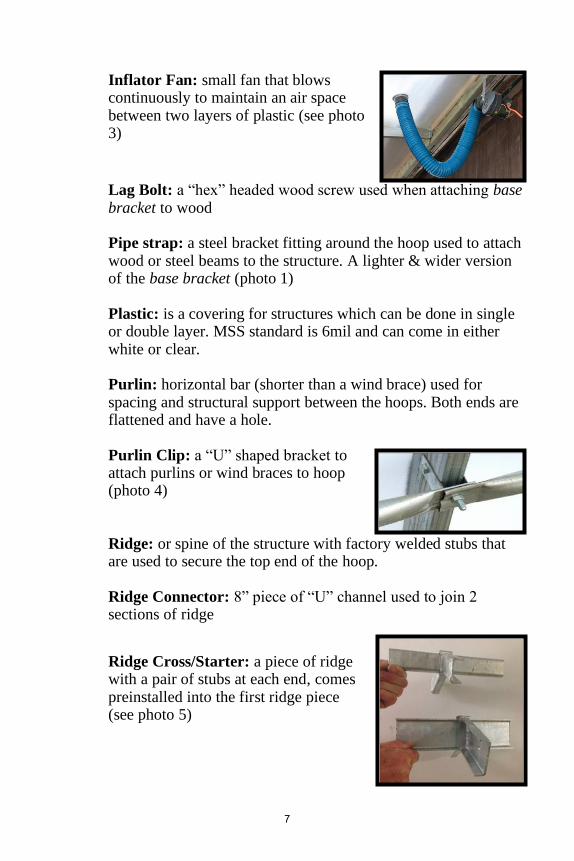
Inflator Fan: small fan that blows continuously to maintain an air space between two layers of plastic (see photo 3)
Lag Bolt: a “hex” headed wood screw used when attaching base bracket to wood Pipe strap: a steel bracket fitting around the hoop used to attach wood or steel beams to the structure. A lighter & wider version of the base bracket (photo 1) Plastic: is a covering for structures which can be done in single or double layer. MSS standard is 6mil and can come in either white or clear. Purlin: horizontal bar (shorter than a wind brace) used for spacing and structural support between the hoops. Both ends are flattened and have a hole.
Purlin Clip: a “U” shaped bracket to attach purlins or wind braces to hoop (photo 4)
Ridge: or spine of the structure with factory welded stubs that are used to secure the top end of the hoop. Ridge Connector: 8” piece of “U” channel used to join 2 sections of ridge
Ridge Cross/Starter: a piece of ridge with a pair of stubs at each end, comes preinstalled into the first ridge piece (see photo 5)
7

Ridge Stub: an angle cut u-channel which is welded to the ridge steel tube. It goes into the top end of the hoop. (diagonal pieces on photo 5)
Roll up sidewall: a mechanism to allow the full-length cover of the structure to be opened up. Usually both sides have the capacity for roll up (see photo 6)
Sill Plate: usually a double 2x6 or 2x8 placed on top of the posts, it bridges the gap between the posts or ties the base beams together. In the case of a railroad tie, it also gives consistency to the top surface to allow level construction of the building Speed Screw: a hex head screw that drills and taps its own hole (#14 is heavier than #12) Tarp: is a woven form of plastic which has much greater tear resistance. MSS standard is 12mil and can come in either white or green. Wind Brace: similar tube to a purlin (although longer) and installed diagonally at each corner of the structure. The quantity per corner depends on the structure. **SEE WIND BRACE INSERT FOR DIRECTIONS**
Wirelock Channel: an aluminum channel generally installed on the first and last hoop where cover is inserted. It can also be used at the top and/or bottom of the roll up. (see photo 7, left) Wirelock Insert: the “zip-zag” stainless, heat-treated steel wire used in the wirelock channel to hold the covering in place (see photo 7, right)
8

We will mention again, if there is anything you do
not understand as you go through this manual, please make note and call or email the office
BEFORE you start to build.
If questions come up as you’re building, please contact us as soon as you can, to avoid having
something go wrong with the installation that could have been prevented, and may void the warranty
Please read over the complete instructions
BEFORE starting installation.
A photo “slideshow” is included at the end of the installation manual and meant to be used IN
CONJUNCTION with the rest of the manual and NOT to be used as a substitution.

WINTER CARE: Snow & Wind Load
Our structures are designed in a gothic shape with a slippery cover to be lightweight and snow resistant. This encourages the snow to slide off quickly. This is not an industrial high snow load building. We do our best to always point out applications where the capacity of the structure is being compromised. Extra hoops are an economical way to increase wind and snow load capacity. We take pride in the sturdy shelters we manufacture and supply, but must point out that we cannot warranty against weather conditions. Snow removal, when occasionally required, is a simple task. Uneven snow loading is deceiving, since the total weight is not a problem but the lateral force can cause the hoops to distort.
It is rare to have any significant snow build up on the roofs;
however, unless you have built your structure with 2’ or 3’ hoop spacing, you must have provision for snow removal in certain
situations.
DO NOT GO INSIDE A BUILDING WHERE THERE HAS
BEEN OBVIOUS STRESS! Be aware of these scenarios where excessive snow build up is
possible and damage could follow:
• A wet snowfall followed by dropping temperatures
• A building 90° to the prevailing wind (drifts could form on the backside of the building)
• A building attached to and situated downwind of a taller building (significant drifting)
• A building 90° to another building that has a higher roof, could cause a surge in snow weight when the snow on the upper roof slides off
10

Preventative measures for excessive snow build up (where possible):
• Build structures in-line with the prevailing wind
• Build structures level from side to side to create uniform shedding
• Do not attach your building to a larger existing building
• Install a heat source to melt the snow Economical additions to increase your structure’s snow resistance:
• Install cable or tubular cross-ties at each pair of hoops, to create a triangle (when using cables there is no need to put them under tension)
• Place wooden or metal support posts under the ridge. These can be suspended from the ridge with no more than ½” ground clearance. This will provide support as soon as there is load and structure movement will not dislodge your supports.
• Use closer hoop spacing for the first 12’ section away from another bigger building
Pointers for removing snow:
• NEVER remove all the snow from one side and then the other
• Remove the snow off the top of your building before using a machine (snow blower, etc.) along the sides
• Use a padded piece of 1x4 wood on a pole (create a “T” shape) as the best tool for gently bumping the inside of the cover
BEWARE of this sequence which creates a “worst case
scenario”: Freezing rain, followed by dropping temperatures, followed by a lot of snow followed by rainfall. It is easy to triple the weight of the snow load in 30 minutes.
11

Anchor Posts
Anchor Posts are NOT used in combination with Base Brackets
**A word of caution…recommendations made for anchoring are based on years of experience. Ultimately the customer is
responsible to properly anchor a structure. **
Anchor Posts MUST BE SET into concrete when:
• the soil has been recently excavated (within the last five years)
• it is required by the building code (use of concrete usually classifies the building as permanent)
• extremely windy and exposed areas exist (at least use on the corner posts)
• more than 10% of the anchor post will be out of the ground (upgrading the anchor post size may be needed)
• there are areas where erosion has been a problem in the past
Anchor Posts SHOULD NOT be used when:
• the soil is a very heavy clay (heaving would be a constant problem)
• there is a shallow rock layer
• there are major amounts of rocks interfering with the accuracy of the anchor post setting
• the structure will be moved shortly (anchor posts must be cleaned out before reusing)
USE BASE BRACKETS INSTEAD IN THE ABOVE CASES
12


Setting Anchor Posts
1. Level the side to side area where your structure is to be erected. (A small end to end slope is acceptable).
2. Lay the ridge along your string line for a quick and accurate way of marking the post spacing. (the spacing of the posts will be the same as the spacing of the stubs on the ridge)
3. Use a chunk of hardwood to protect the anchor post tops from the blows of the sledge hammer. Anchor posts can also be pushed in with the bucket of a tractor. You must still provide hardwood protection for the top
4. Anchor posts will rotate as they are pounded down, this
can be easily straightened with a pipe wrench (holes should face side to side). It is best to rotate them to the correct spot with about 2” to go and then finish the job.
5. The post top should be 3”-5” above grade. 6. If installing a 2x6 wood baseboard use pipe straps installed
below bolt connection to hoop. 7. Having the holes of the anchor posts on a flat plane is
CRITICAL to the straight construction of your building.
Dealing with Damaged Anchor Posts
If a post top becomes burred or bend a bit, simply hit them between two hammers to bring the width down to ¾” again. If the top of the post is not salvageable you can cut ½” to 1” off the top without further consequence.
If you encounter a large rock, you can cut a post back ONLY IF there are no more than 1 or 2 per side, if it is not one of the first 3 from the end AND you are not cutting more than 1/3 off the
post. If you cannot conform to these criteria, give us a call for “plan B”. If an anchor post is deflected off the intended direction, it can be bent to direct in closer to its intended location.
14

Base Brackets
Base Brackets are NOT used in combination with Anchor Posts
Although the building can be anchored directly into the ground, (see option: anchor posts) it can sit on a slab, curb or beam or it can be elevated on some sort of a wall. Base brackets with lag bolts are supplied to fasten the building to the chosen form of foundation.
. Please see video online “How to Install Anchoring to the Base Beam” for further instructions
A word of caution…recommendations made for anchoring are based on years of experience. Ultimately the customer is responsible to properly anchor a structure
• The outside to outside measurement of the wall or beam should be slightly greater than the width of the building. (+3” for 1x2 hoops and +5” for 1x3 hoops)
• If the center of the base bracket is more than 2” from the edge, there will be a ledge where there is the potential for damage to the cover as the building is shedding snow or ice.
• The overall length of the beam or wall should also be an extra 4”, unless you plan to have a solid end covering.
15

Base Beam
By using 3 layers of 2x6 rather than a 6x6 beam (as seen in the pic), you can create a continuous laminating effect by offsetting the layers. By trimming 1” off of the middle board, you get 2x6, 2x5, 2x6. This creates a “pocket” where the side of the cover can be secured.
There simply is no such thing as too many anchors.
Anchoring the Beam
• With the exception of the large concrete blocks, the base
needs to be anchored to prevent lateral shifting and/or uplift.
• Spiral earth anchors or T-bars can be used to anchor beams (usually 2 per pair of hoops). Leaning these in an alternating pattern creates extra holding capacity.
• Anchors MUST be to the inside of the beam. In case of multiple beams (stacked) the anchor must be attached to at least two layers. Rebar through the beams does not have
sufficient holding power.
• The AVERAGE spacing of your anchors should never be more than 4’ unless you are in a forest. Towards the corners, the anchors are usually closer to each other and along the middle they can be slightly further apart.
• There must be a minimum of 2 fasteners per post.
16

Setting Wall Posts
Putting some concrete into the bottom of the hole significantly adds to the holding capacity.
Posts should always be set below the frost line and have at least as much length below the surface as above.
• When auguring holes to set posts, extreme care should be exercised to pack the soil around the posts firmly.
• Spacing the posts further apart usually does not save any time or money since extra time will be spent packing the soil (also greater need for concrete) and a heavier sill plate will be required.
• There should be a horizontal board on the outside of the posts just below grade. This will give extra protection against posts leaning outward.
Sill Plate
The sill plate bridges the gap between the posts or ties base beams together. In the case of a railroad tie it also gives consistency to the top surface to allow for level construction of the building. If the sill
plate is capping something else (i.e. beam) then a 2x4 is sufficient. A 2x6 sill plate between posts is sufficient unless the post spacing is more than 4’. Unless you are building on a beam you should add a
2x4 on edge as a place to fasten the cover. The joints should always be offset to create extra strength.
Base Bracket placement
Place 2 parallel runs of the base brackets on the beam or wall. The center to center spacing between these lines is equal to the width of your building. The in line spacing is equal to the specified hoop spacing of the building you purchased. Each bracket is secured with 2 lag bolts which MUST be in line with the length of the building.
17

Ridge
Please note that quantities of pieces and stub spacing will vary order to order.
The ridge is the very top part (the spine) of your structure. Stubs are welded on every 2, 3, 4 or 6 feet according to the requirements of your particular structure. It is onto these stubs that the hoops will be fastened.
A few points about the Ridge: It is mandatory that you report any ridge damage
before starting the assembly
• Always check the top of the ridge for galvanizing burrs or rough edges and grind off if necessary.
• Hairline cracks in the galvanizing are surface only and no cause for concern.
• The ridge section with a pair of stubs at both ends is your ridge cross or starter. The connected piece of your starter NEVER goes on the end. It faces inward and connects to the open end of the next ridge section (see drawing and photo 4)
• The joints of the ridge may not line up perfectly. A couple wraps of duct tape will protect your cover. (see photo 1)
• For 1x2 steel use #14 3/4 speed screws. The hoops are secured to the ridge with 4 #14 speed screws.
• It is a good idea to make the holes of the 1x3 ridge while it is still on the ground.
18

Ridge Cross/Starter
This is a piece that is supplied by MSS, usually preinstalled, into the first ridge. This ridge is flipped around to connect in with the rest of the line of ridge pieces you will be installing.
The diagram below depicts 4’ spacing only. If you have 3’ hoop spacing, you will have 4 pairs of stubs per ridge; 2’ spacing has 6 pairs of stubs per ridge; and 6’ spacing has 2 pairs of stubs per ridge. Also, please note, larger structures will have more ridge in the line for connecting. If your structure is not a multiple of 12’ your starter ridge section will be shorter and may not have the “standard” number of stubs as mentioned above.
The ridge cross/starter is always used to join the first and second
length of ridge together. Two #14 speed screws on either side of the connection, from the bottom are used.
19
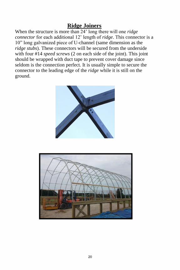
Ridge Joiners
When the structure is more than 24’ long there will one ridge connector for each additional 12’ length of ridge. This connector is a 10” long galvanized piece of U-channel (same dimension as the ridge stubs). These connectors will be secured from the underside with four #14 speed screws (2 on each side of the joint). This joint should be wrapped with duct tape to prevent cover damage since seldom is the connection perfect. It is usually simple to secure the connector to the leading edge of the ridge while it is still on the ground.
20
See our YouTube Channel for more
information on all the pieces mentioned in this manual, as well as cover installation tips
and more
If there is a topic you would like to see more information on, either a more detailed article or
video, please send us an email and we will do our best to make one available.
We are also available at the office to answer any questions that come up while you are reviewing
this guide prior to installation, or during. Unfortunately, we aren’t available for emergency
calls, so please ensure you have everything reviewed during business hours prior to starting
your installation

Hoops
Be aware of safety and use a scaffold for putting up the larger structures, especially when building the unit on a wall.
The curved part of the hoop is usually the bottom; the straight part is the top. For structures that have been supplied as a cathedral unit (for RV, boats, etc.) the curved part goes up and the long straight part goes down.
CRITICAL NOTE:
When the FIRST SECTION of the ridge is complete,
secure with a guide rope so that everything stands
vertical.
The guide ropes must go both ways as an inverted V and secured with some sort of anchoring post.
If you do not plumb the building NOW, it will be much more difficult later.
22

Always put hoops up in pairs for better balance and stability. Apply downward pressure on the top edge of the hoop.
The fastener ALWAYS goes horizontally. For the remaining ridge sections:
1. Always secure to the connector of the previous ridge first 2. Then secure the last pair of hoops and then do the
intermediate hoops. 3. Sometimes the end of the hoop has a dimple, this can be
removed with pliers or the claw of a hammer. 1 x 2 Hoops with Base Brackets
• hold the ridge at the appropriate height, short scaffold is best, but 2 step ladders will also work
• slide the top of the hoop over the ridge stub and secure with a #14 speed screw
• slide the bottom of the hoop over the base bracket and secure with a #14 speed screw
1 x 2 with Anchor Posts
• Always fasten the bottom first and then insert over the ridge stub.
• The top of a 1 x 2 hoop is secured with a #14 speed screw.
When your building has 1 x 3 ribs 1. Always bolt the top first. 2. The person on the ground can move the hoop so that the top-
hole lines up. 3. The base bracket or anchor post is done second.
Hoops for a Lean-to
• set your base beam and secure your base brackets to the beam at required spacing
• attach header (2x4 or 2x6) to wall at predetermined height
• attach wall brackets to header slide top end of hoop over top bracket, and place end of hoop on bottom bracket
• apply downward pressure on top of the hoop while fastening hoop to bracket with self-tapping screw, then complete tightening of lag bolts at the top.
23

Purlins
Purlins are the horizontal spacers in between the hoops used to maintain rigidity in the structure. They are usually 1 ¼” round with
both ends flattened. Be sure that the structure is standing perfectly vertical before attaching the purlins
(use level to determine if building is leaning)
The holes drilled in each end are spaced at the same spacing as the hoop spacing. The tabs with the holes of 2 purlins overlap and are bolted to the underside of the hoop (structure). If they are installed on the outside, they will prevent snow from sliding off and also create drip lines.
• Before you can attach the purlins, you must insert the 1” carriage bolt into the center hole of the Purlin Clip (1-1/2” C. bolt if there will be a cross-tie). The square shoulder of the C. bolt should nest squarely in the square hole of the bracket. This prevents the bolt from turning when you are installing the lock nuts.
• Then attach all the purlin clips to the hoops with the 1-1/2” Hex Bolt and lock nuts.
• If your structure has 2 rows of purlins and cross-ties, do not tighten the upper purlin clip at this time. You may need some wiggle room to make the cross-tie fit
Notes: The smaller structures have 1 run of purlins per side and the larger structures have 2 runs per side. One run of purlins is
sometimes eliminated if you are using roll up sides. Long cross-ties or cross-ties in heavy load areas will require mid support and lateral bracing. Keep in mind that adding a cross-tie decreases the usable height of your building, usually by 24-36 inches.
24

If your building has cross-ties which are installed on the purlin clip, leave the purlin clip loose so that you will have a little more “wiggle” room for installing the cross-ties later. (see diagram below)
25

Wind Bracing
Wind braces look like purlins except they are about 50% longer.
They are installed diagonally in all four corners AFTER the purlins have been secured. Please see how to video online for
further clarification
A note about the length of the wind braces
You will not likely end up perfectly at the base or the next row of purlins (in the case of multiple rows of purlins). You can cut and re-flatten the brace if it is too long. It is equally OK to fasten it near the base or purlin if the last brace is a bit too short. It is acceptable to secure the bottom end of the last brace to the base, rather than the hoop if this fits better
The quantity of braces depends on the structure size and certain construction details. Usually the small structures have 1 per corner, mid-sizes have 2 per corner and larger structures have 3 or 4 per corner. When building on a wall or in a very windy location, it may be
advisable to double up on the braces. Structures with 3’ hoop spacing will have more, shorter braces.
• The starting point for each row of braces is the connection point of the purlin to the last hoop.
• Each brace will aim down to the next hoop at approximately 45 degrees
• If you have 2 or 3 rows of purlins, you repeat the process for EACH row.
26
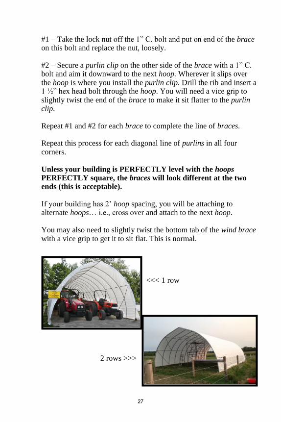
#1 – Take the lock nut off the 1” C. bolt and put on end of the brace on this bolt and replace the nut, loosely. #2 – Secure a purlin clip on the other side of the brace with a 1” C. bolt and aim it downward to the next hoop. Wherever it slips over the hoop is where you install the purlin clip. Drill the rib and insert a 1 ½” hex head bolt through the hoop. You will need a vice grip to slightly twist the end of the brace to make it sit flatter to the purlin clip. Repeat #1 and #2 for each brace to complete the line of braces. Repeat this process for each diagonal line of purlins in all four corners. Unless your building is PERFECTLY level with the hoops PERFECTLY square, the braces will look different at the two ends (this is acceptable). If your building has 2’ hoop spacing, you will be attaching to alternate hoops… i.e., cross over and attach to the next hoop. You may also need to slightly twist the bottom tab of the wind brace with a vice grip to get it to sit flat. This is normal.
<<< 1 row
2 rows >>>
27

Cross-ties Cross-ties are an inexpensive way to reinforce your structure, typically increasing the snow/wind load by 5 pounds per sq. ft. They are made from the same material as the purlins and wind-braces and, depending on the width of the structure, between 10 and 14 feet long. In cases where the cross-ties are not included in the package they are available as add-ons. They are installed under the ridge and span across the width of the structure from hoop to hoop. If your structure has two rows of purlins the cross-ties are fastened at the top purlin sharing the purlin clip. If your structure has one row of purlins, there will need to be a hole drilled above that row at the height at which the cross-tie is to be installed.
If your building has cross-ties which are installed on the purlin clip, leave the purlin clip loose so that you will have a little more “wiggle” room for installing the cross-tie later.
Long cross-tie or cross-ties in heavy load areas will require mid support and lateral bracing.
Keep in mind that adding a cross-tie decreases the usable height of your building, usually by 24-36 inches.
When attaching the purlins, you must first insert a 1-1/2” C bolt into the center of the purlin clip. The size of bolt is slightly longer than normal when you have cross-ties for your structure. If a structure has two rows of purlins, the cross-ties will be attached at the upper row to the same bolt as the purlins. Make sure the purlin C. bolt is 1-1/4” long. You can leave the lock nut on and simply add another nut over the cross-tie. If you do not have two rows of purlins, your cross-ties are much shorter and you will need to drill holes to secure the purlin clips.
28

You will need to slightly bend the purlin clip tabs down to match the angle of the bolt. Be careful not to over bend! When there is a two-part cross-tie, there will be a threaded rod which is both the center support and the joiner. The threaded rod is suspended from the ridge on a purlin clip (double nutted). The purlin clip is secured to the ridge with two speed screws. There is also a nut above and below where the two parts of the cross-tie overlap.
Cross-ties are not normally supplied for the two end pairs of hoops since this would interfere with the end framing.
They are strongly recommended to be purchased if your
building is open ended.
29

Plastic Roof Covering (In Preparation)
Please see how to videos online for further clarification
Regardless of which covering will be installed on your building, the success or failure of the job, and your safety, will often be determined by the preparation and understanding of the task ahead.
The following is a checklist BEFORE you actually rolling out your cover.
The top edge of your ridge should have been checked for roughness when you were installing it. Make sure these have been filed down.
If your building is longer than 12’ the ridge will have one (or more) connectors. These should be wrapped with duct tape.
If your wirelock channel was not installed continuously over the crest, this edge should also be covered with duct tape.
If your building includes roll up side walls, the mechanism for securing the cover at the top of the roll up should be complete before proceeding. (It can be done later, but is significantly more complicated).
You will require a ladder (or other elevating device) for comfortably reaching the peak at BOTH ends of your building as well as 2 thin ropes that are a minimum length of ¾ of your cover width (to assist in pulling the cover over).
30

Your covering fasteners for the sides should be distributed along the sides (tucked against the building so as not to get in the way). If you are using spruce strapping, it saves time if you put all the screws in first. Pre-drilling, as well as setting screws and washers will save the wood from splitting.
Walk along the side of the building where you will unroll your cover. Check for and eliminate sharp objects (broken off weeds are especially bad). If an object can’t be removed, the edges should be covered. If there is absolutely NO room to roll out the covering along the building, give us a call to discuss “Plan B”.
Four (or more) people to install the cover are advisable if you have never done this before. It can be done with 2 or 3 but remember, the slower the job goes the more
chance there is of the wind picking up. A couple extra people during the initial pulling over and squaring is helpful. These extra people can leave once the cover is tacked in place.
The effect of wind, even a breeze, will be magnified by the size of your cover. You will be looking at this cover for a long time, wait an extra day if necessary. Early morning or late evening is usually best time of day.
If your ends are covered in plastic it is definitely easier to do the ends before the roof cover goes on. This is because the end plastic normally goes UNDER the roof plastic. At the very least it is recommended to have the end wall framing in place before the roof cover goes on.
If you have a longer building and your cover has come on a cardboard core, make sure you have a pipe to unwind the roll on.
31

Plastic Roof Covering
Please see how to videos online for further clarification
It is CRITICAL that you pull and tighten your cover lengthwise BEFORE doing the sides!
You are now ready to transform your sturdy shell into a functional shelter. Please see our website for additional pointers.
ROLL your cover along the side of the building. Do not drag along ground as cover may snag on something. If you are doing double cover, roll them both out. This way the top one (clean) will become the inside layer.
For most, determining the length and width is straight forward, but if your parts list shows a roof covering close to square, verify that the way you have it rolled out is a minimum of 1’ longer than your building.
Determine the leading-edge corners of your cover. Grab the corner, making about a 12” “tail”. Wrap a rope TWICE around the tail, making a simple tight knot. Take the opposite end of each rope and go to the top of the ladders that you’ve leaned against the peak of the building.
ALWAYS pull the cover to the peak BEFORE the person on
the ground continues pulling. Until the whole cover has crossed the ridge, pull back and forth, lengthwise, in sort of a “sawing” motion.
Make sure that the side that is in contact with the dirt is going to be outside, so the rain can wash it clean.
32

Continue to feed the cover over until it is centered on the building. Precision to the inch is not necessary. Judging straightness is simply a matter of eyeing a fold to one of the purlins. Longer covers will require someone helping it along half way down the side.
Install 12” of wire insert at each side of the ridge, unless you are positive you will not have to adjust it. Put in the rest when any adjustments are made. Don’t allow more than 6” of overhang on the cover.
Go to the opposite end and pull the cover as tight as you can lengthwise. For pulling tight, do not use anything more than human power on the cover wrapped on a short piece
of 1x2 strapping. Having many people pulling on a hot summer day can create a problem of the cover being too tight.
Install a piece of your cover fastener half way down each side of the baseboard. Look along a crease to make sure it is straight. If your building has roll ups, “doing the side” refers to the top of the roll up.
Usually the ends of the cover have been cut squarely. Before proceeding, verify that you have enough material for all
four corners. Make adjustments needed.
For a double cover, repeat the above steps paying special attention to not rubbing the rope over the cover over the ridge.
33

Work from the center to the ends, working the two sides simultaneously. As you approach the end you may need to pull lengthwise as well as down.
If the wind starts picking up, work into the wind or upwind first. If a wrinkle develops, always pull at 90 degrees to the midpoint of the wrinkle.
If you are putting a double cover on, only pull on the inside layer for tightness. The outside layer needs a little slack. If you are putting the cover on in extreme cold you will need to tighten the cover once you have warm weather. Excess roof cover can be trimmed to 2-3 inches once you are certain it is extra and has had a chance to settle.
34

Your installation will either have one cover or the other, Plastic or Tarp.
Plants need clear plastic to be able to grow.
Animals need shade with light, so either white
plastic or white tarp is ideal. White tarp is more durable if animals will have contact with the cover,
white plastic is more economical.
If it is a storage situation, tarp is recommended in case any supplies, vehicles, equipment, hay, etc. come in contact with the cover, tarp has greater
tear resistance and is more durable against bumps.
We do have repair tape available for small nicks or cuts to either type of cover.
If you are looking for Lexan polycarbonate ends or
roof cover, you will need to receive special instructions on handling and installing from Norm.

Tarp Roof Covering (In Preparation)
Please see how to videos online for further clarification
Regardless of which covering will be installed on your building, the success or failure of the job, and your safety, will often be determined by the preparation and understanding of the task ahead. The following is a checklist BEFORE you actually rolling out
your cover.
The top edge of your ridge should have been checked for roughness when you were installing it. Make sure these have been filed down.
If your building is longer than 12’ the ridge will have one (or more) connectors. These should be wrapped with duct tape.
If your wirelock channel was not installed continuously over the crest, this edge should also be covered with duct tape.
If your building includes roll up side walls, the mechanism for securing the cover at the top of the roll up should be complete before proceeding. (It can be done later, but is significantly more complicated).
You will require a ladder (or other elevating device) for comfortably reaching the peak at BOTH ends of your building as well as 2 thin ropes that are a minimum length of ¾ of your cover width (to assist in pulling the cover over).
36

Your covering fasteners for the sides should be distributed along the sides (tucked against the building so as not to get in the way). If you are using spruce strapping, it saves time if you put all the screws in first. Pre-drilling, as well as setting screws and washers will save the wood from splitting.
Walk along the side of the building where you will unroll your cover. Check for and eliminate sharp objects (broken off weeds are especially bad). If an object can’t be removed, the edges should be covered. If there is absolutely NO room to roll out the covering along the building, give us a call to discuss “Plan B”.
Four (or more) people to install the cover are advisable if you have never done this before. It can be done with 2 or 3 but remember, the slower the job goes the more
chance there is of the wind picking up. A couple extra people during the initial pulling over and squaring is helpful. These extra people can leave once the cover is tacked in place.
The effect of wind, even a breeze, will be magnified by the size of your cover. You will be looking at this cover for a long time, wait an extra day if necessary. Early morning or late evening is usually best time of day.
If your ends are to be covered with tarp you MUST do the ends before the roof. If your ends are covered with anything else, at least the framing should be done before doing the roof. It is easier to have the ends covered first but sometimes perfect roof covering days are scarce and should not be passed up.
If you have a relatively short building, spending the time to mark the center of your tarp (for the width) will make it considerably easier to get the cover on square and straight. Do this at both ends
37
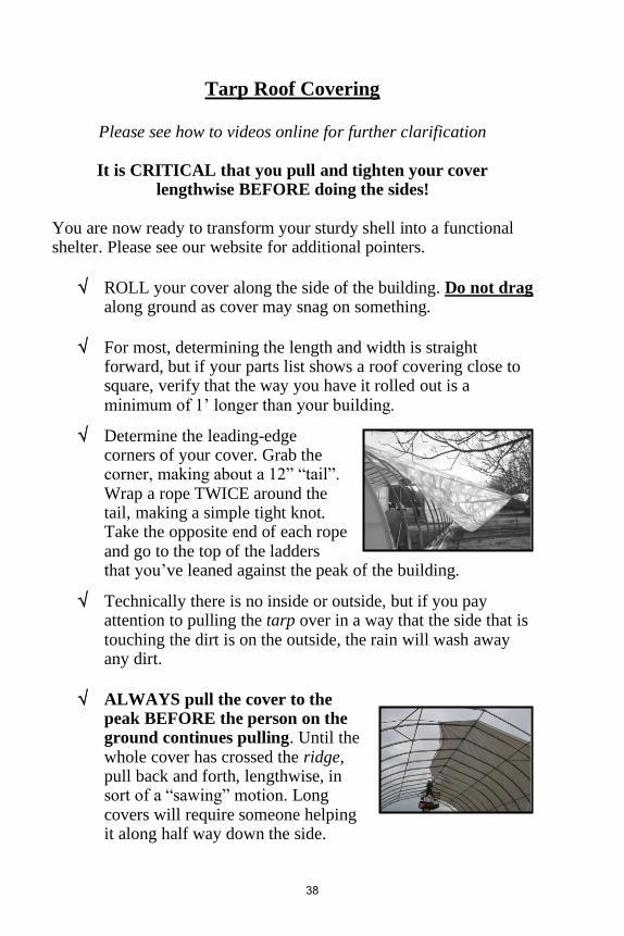
Tarp Roof Covering
Please see how to videos online for further clarification
It is CRITICAL that you pull and tighten your cover lengthwise BEFORE doing the sides!
You are now ready to transform your sturdy shell into a functional shelter. Please see our website for additional pointers.
ROLL your cover along the side of the building. Do not drag along ground as cover may snag on something.
For most, determining the length and width is straight forward, but if your parts list shows a roof covering close to square, verify that the way you have it rolled out is a minimum of 1’ longer than your building.
Determine the leading-edge corners of your cover. Grab the corner, making about a 12” “tail”. Wrap a rope TWICE around the tail, making a simple tight knot. Take the opposite end of each rope and go to the top of the ladders that you’ve leaned against the peak of the building.
Technically there is no inside or outside, but if you pay attention to pulling the tarp over in a way that the side that is touching the dirt is on the outside, the rain will wash away any dirt.
ALWAYS pull the cover to the peak BEFORE the person on the ground continues pulling. Until the whole cover has crossed the ridge, pull back and forth, lengthwise, in sort of a “sawing” motion. Long covers will require someone helping it along half way down the side.
38

Continue to feed the cover over until it is centered on the building. Precision to the inch is not necessary. Judging straightness is simply a matter of eyeing a fold to one of the purlins.
Install 12” of wire insert at each side of the ridge, unless you are positive you will not have to adjust it. Put in the rest when any adjustments are made. Don’t allow more than 6” of overhang on the cover.
Go to the opposite end and pull the cover as tight as you can lengthwise. For pulling tight, do not use anything more than human power on the cover wrapped on a short piece of 1x2 strapping. Having many people pulling on a hot summer day can create a problem of the cover being too tight.
Install a piece of your cover fastener (wirelock) half way down each side of the baseboard. Look along a crease to make sure it is straight. If your building has roll ups, “doing the side” refers to the top of the roll up.
Usually the ends of the cover have been cut squarely. Before proceeding, verify that you have enough material for all four corners. Make adjustments needed.
Work from the center to the ends, working the two sides simultaneously. As you approach the end you may need to pull lengthwise as well as down. If the wind starts picking up, work into the wind or upwind first. If a wrinkle develops, always pull at 90 degrees to the midpoint of the wrinkle.
39

If the wind starts picking up, work into the wind or upwind first. If a wrinkle develops, always pull at 90 degrees to the midpoint of the wrinkle.
Excess roof cover can be trimmed to 2-3 inches once you are certain it is extra and has had a chance to settle. If you are putting the tarp on in cold weather, you will likely have to tighten the cover once you are into warm weather.
40

You will be given a separate set of instructions if you have chosen a gable roof vent or other
ventilation options.
Roll up sides with Standard Inflator Fan are our most common ventilation options and why they are
included in this manual.
Please don’t hesitate to reach out if you have any questions about other options or packages you have
purchased.
41

Roll up Side Walls Installing the top of the roll up wall at 4’ above the grade is considered average.
2’ – 3’ is suggested for very windy and exposed areas 5’ – 6’ works better for very sheltered locations.
Whichever way you choose, mark each hoop individually or put up a tight string line at the desired height.
Using Wood
1-Secure a pipe strap with a #14 Speed Screw to each hoop at this point. If the screw head is a potential rubbing point by putting it on the inside of the hoop, it can also be put on the long side. 2- Fasten the 2x4 along the outside of the hoop, to the flat tabs of the pipe strap with two 2-1/2” carriage bolts. Hold the wood in the desired location and use the holes in the pipe strap as your guide to drill two holes through the wood. Insert the carriage bolts from the outside with the nut inside (do not use lock nuts).
As an alternative to using the wood continuously on the outside, it can be cut to 46 ¾” long (or 1-1/4” less than the center to center of your hoop spacing) and fastened between the hoops. This makes the structure stiffer and eliminates the bump.
Rather than crossing over the end hoop trim the beam for length
and push it inward so that it butts into the end hoop. This allows for an even seal of plastic and wirelock on that end hoop.
42

3- Either nail a strip of spruce strapping to the 2x4 so that it is flush to the top or fasten your wirelock with the wood screws provided.
Make sure the joints are off set from each other. If you are using wirelock, determine where your upper eyebolts will be and instead of putting a screw there now, drill through the 2x4 (remains open for now) (see photo) 4- If you are using wirelock along the sides, start from the middle and work toward the ends. If you are using wood, put the screws into the strapping before unrolling the cover.
The minimum is 8 screws per 8’ piece.
Putting the wood screw through a washer will increase the tightness while minimizing the risk of splitting. If you have a DOUBLE COVER, in at least one place per side, you should cut off 6”-12” of the strapping, and install that piece separately. This will allow you to remove this section to let the air from the top escape to the sides at the appropriate time. Or you can run a “jumper hose” from the inflated top to the roll up area in order to inflate the lower area when needed.
Using Steel
1- Often the 1”x2” steel tubing replaces the lower purlin. Drill and bolt one side of the pipe strap, the other side can be fastened with a speed screw.
2- Push the end of the steel in so it butts into the end hoop and goes under the tab of the last pipe strap.
3- Fasten the wirelock to the side of the steel tubing with the small speed screws. Cut 12” off the first piece to ensure that the joints of the steel and of the wirelock are offset from each other to add strength and rigidity to the assembly. 4- When the cover is centered over the building, begin inserting the wire inserts at the middle and work toward the ends.
43

The following applies to both steel and wood applications
Screw in eye-bolts are supplied for wood and threaded eye-bolt with
double nut for steel 1- The first eyebolt is installed where the top of the roll up meets the first hoop. Double nuts and washers are supplied so that there will be a nut and a washer both inside and outside of your upper baseboard. The second eyebolt goes as low as possible on the base where it meets the next hoop in from the end. If your base is a beam, drill a ¼” hole 2” deep and simply screw in the eyebolt. The next eyebolt goes up at the next hoop. Continue up and down every 4’ for the balance of each side. 2- Use the lower eyebolts as your guide to fasten the roll up pipe. When the pipes and the handle are fitted together, the square part of the handle should be 6” past the end of the building. Bring the cover around the pipe, tugging only enough to remove wrinkles. 3- Sandwich the cover between the pipe and the curved aluminum strip. For now, put 2 speed screws per piece. It is important to have a screw wherever there is a joint in the pipe. Roll up the pipe to confirm it is rolling straight. If no adjustments are required then put the rest of the screws in (8 per 8’ aluminum strip) 4- Thread the braided rope which is supplied, continuously through all the eyebolts. This rope holds the pipe against the building during windy conditions. It is usually tightened somewhat during the winter.
44

Wirelock aka “wiggle wire”
(consists of channel and insert)
Most buildings come with enough wirelock to be installed on top
of the first and the last hoop. Additional wirelock can be purchased to run along the side wall, or to be used to attach covering to the end framing or doors if desired.
The end wall tarp is sandwiched between channel and hoop,
inserts hold the roof tarp) Please see videos online for further clarification
By installing the end channel and then removing it to install the end cover, your channel will be pre-bent and have the correct holes.
• Generally, the channel is installed on the top of the end hoop with the open side UP
• The plain channel does not have a front or a back, it is symmetrical.
• Start at the bottom of the end hoop and work your way up, generally centered on the hoop
• Secure with #12 x 3/4” speed screws at 12” centers, (small head screws give less wire interference)
• Carefully line up the ends of consecutive pieces to eliminate edges which can tear the cover
• Once you get to the top of the hoop, simply lean on the channel to bend it and then go down the other side
• If you must cut at the top, wrap the ridge with duct tape to prevent cover tears
• You will need to cut the last piece of channel to make it fit
• If your structure is butted against a building it is easier to install the channel on the bottom of the hoop (please call for some additional instructions)
45

Side Wall Cover Fasteners (you have 3 choices)
Notes: Pipe Straps are supplied when a structure has roll up side walls and/or anchor posts options. When base board (wood or steel) is fastened with pipe straps, the base board should be pushed in so that it butts into the last hoop
wood strapping
wood strapping
46

There are a few different options for inflator fans and the following pages cover some ideas for our standard inflator
fan, solar power, and solar power alternative.
Please don’t hesitate to reach out and ask any questions to our staff to find the right fit for your application.
There are also more videos about roll up sides on our
YouTube Channel, as well as more detailed articles on our website.

INFLATOR FANS
Please note solar powered options will be available if you do not have a convenient electricity source near the structure. There are
separate instructions for this option.
An inflator fan is a small blower which puts air in between two layers of roof cover on a greenhouse. Benefits of inflator fans are:
• to achieve some degree of heat efficiency (up to 30% reduction in heat loss).
• virtually eliminates condensation (by ensuring that there are no holes in the
cover and making sure the edges are sealed, you will create the dead air space required)
• ensures the cover is always tight since you simply get more air during warm weather
• creates longer cover life since nothing is ever rubbing on anything.
• reduces wind stress on the structure since it acts as a shock absorber.
The best location for the inflator fan is the corner from which the prevailing wind comes, usually the north or west side. (suggestion only) Usually the unit draws inside air. If you are in a very high humidity application, it would be advisable to draw outside air.
Most inflator fans come with a hanger plate rather than a mounting board. The mounting bracket of the fan can be fastened to the end framing or to the end hoop. The direction of the output is determined by convenience.
The motor shaft MUST be horizontal because of the type of bearings used.
adapter
48

Plug the fan in for a few seconds to make sure it is working properly. The adapter is usually attached 2’ to 3’ down from the ridge and 1’ to 2’ in from the outside edge. A double output fan has the adapters secured equal distance from the ridge.
1. Using a pen or pencil, make a small hole in the inside layer where you wish to install the adapter.
It is CRITICAL that you make the small hole with a pen or
pencil THEN stretch it bigger. This is the ONLY way the flange will be sealed!!
2. Stretch the hole to an approximate 2” diameter. 3. Before inserting the adaptor into the hole, make sure the wire
reinforced hose is attached to the adapter. Secure hose to adapter with electrical or duct tape (electrical tape is best).
4. There is a notch in the flange of the adapter, hook this into the edge of the hole in the plastic and rotate once. The flange should now be in between the two layers of cover.
5. Slide the free end of the hose over the blower adapter. Secure with electrical or duct tape.
6. If you have to stretch the hose a lot, it is too short and the blower should be moved closer. If the hose hangs with a kink it is too long and should be trimmed.
7. Larger structures will get a dual output inflator which means you will repeat steps 1-6 for both sides of the ridge.
8. The time it takes to completely inflate will depend on the size of the structure. 4” of air space is ideal. It should not take a great deal of effort to push the outside layer against the inside layer.
9. If the air does not go over the ridge, undo some of the wire inserts and slide a 12” piece of garden hose between the two layers. This artificially creates a place for the air to move.
These motors run quite warm but are intended to run continually. There is no need to periodically oil them. When units get older, it may not always start by itself after a power outage. The motor should not make any more sound than humming.
49

INFLATOR FAN ALTERNATIVE After a number of requests and the changing environment, we have been experimenting with a solar collecting package to determine what is required, and the first thing that must be emphasized, is that you MUST use a squirrel cage type of fan and not a propeller type. The propeller type can not continuously run against back pressure. The output required will be determined by the size of the greenhouse or livestock building. Our regular 110 volt fan draws .25 amp and puts out 80 cfm.
Some small buildings can use a smaller fan and some of the bigger ones require our double output fan which gives 130 cfm. Our inflator fan works quite well going through an invertor. Any 12 or 24 volt fans which we have tried have been extremely noisy and therefore not feasible. The biggest challenge which we encountered, is that the specific time the fan is needed the most for heat insulation, is also the time where there is the least capacity for generating power. We used a single solar collector and a single battery and there was simply not a large enough capacity for the battery to hold charge when we had several consecutive cloudy days in December/January. To add another solar collector to an already fairly expensive package, really becomes prohibitive and can deter from moving forward with it. Based on this experience, we wanted to offer an alternative that balanced economy with feasibility. We have come up with a way where the extra roof plastic can be used on the inside of the structure.
This means that you would not need the inflator fan but still have the effect of double plastic with the air pocket for better heat efficiency. This system does require a bit of extra “fiddling” but the net cost will be a little less.
50

1. The structure is covered with a single layer of plastic just the same as you would if you were only doing a single layer.
2. Take the second piece of plastic inside the greenhouse and fold it double lengthwise.
3. This double plastic will be attached to the underside of the ridge using the same aluminum as you would use to fasten the plastic to the roll up pipe.
4. Next remove the purlins from the one side of the structure and after you have pushed over the plastic, reinstall the purlins under the plastic. You will be pushing the bolts through the plastic.
5. The plastic will be fastened with wirelock to the underside of the end hoops.
We have already had some customers try this out and are very happy with the result. Please call us with any questions or to discuss your specific application and situation where you might use this. We would be happy to help you with your project!
51

Ends - Considerations There are as many ways of framing an end wall as there are customers, making it virtually impossible to come up with a detailed set of assembly instructions for each case. Other than a few basic principles to keep in mind, what does the job for you is the best way The basic choices for ends:
1. CLOSED OR OPEN END – The combination of some uses and structure shapes make open end(s) desirable since the entire end would be a door-way and a rectangular frame door is not big enough.
An IMPORTANT WORD OF CAUTION - Extreme caution must be exercised if the intention is one end permanently closed
and the other open. If the open end is facing the prevailing wind, you are setting yourself up for problems if there is no capacity
for incoming air to escape.
2. WOOD OR STEEL FRAMING – for most people, wood is easier to work with and less costly. The down side is that it doesn’t last as long as steel. Generally, the larger the building the larger
the framing. The larger the framing, the further it can be spaced. Framing must also be sized to the weight it will carry (i.e. fans, doors).
52

3. COVERING TYPE – in our packages the end covering is usually the same as the roof, either clear plastic, white plastic or woven tarp. These are very inexpensive but not as durable, especially when there is a lot of handling. We can also supply Lexan or Dyneglass where appearance, long life and light transmission are important. Plywood or sheet metal can be installed where appearance, long life and non-light transmission are important. 4. CLOSED ENDS OR DOORS – requirements are usually determined by accessibility requirements. Inside hinged or sliding doors are not restricted by snow on the ground but do require inside space to move. Sliding doors on the outside can extend past the building but are harder to seal. Roll up tarp doors are low cost for the size opening they provide but are usually a little higher maintenance and cannot be sealed easily. (see separate page-Doors) 5. OPENING REQUIREMENTS FOR FORCED OR NATURAL VENTILATION (if required) need to be considered BEFORE starting to close an end. Fans and louvres will also limit your choices of doors.
53

End Walls Covering & Framing
“frame” in this segment refers to whatever material you are using for the end, NOT to the structure itself
• For soft cover end walls OR if the desired effect is to have the framing flush to the face of the hoop, refer to “A” (below) for the framing and the “D” for the covering.
• For hard cover end walls, refer to “A” for door posts (if required) “B” for the vertical framing, “C” for the horizontal framing and “E” for covering.
If the two center frames will be door posts, the INSIDE measurement for hinged doors is ½” GREATER than the door frame and for sliding doors it is 2” LESS than the door frame. The vertical frames MUST be attached to a sill which is anchored or they require their own anchor posts.
➢ A. Stand the wood or steel framing member in its desired
location against the INSIDE of the hoop. From the OUTSIDE, mark the frame along the TOP and BOTTOM of the hoop. Along the top line cut the frame off so that now the top is the same angle as the hoop at that point. On the lower line only cut 1” deep and then cut vertically. This creates a notch matching the angle of the hoop. Drill and bolt horizontally. Repeat as often as is required for each end.
➢ B. Stand the frame in its desired location against the INSIDE
of the hoop and place a mark along the TOP of the hoop from the OUTSIDE. By cutting off along the line the top of the vertical will be angled the same as the hoop. Drill and bolt horizontally. Repeat as often as required.
54

➢ C. Horizontal frames are spaced appropriate to the cover
strength. The outside end is angle cut to the angle of the hoop and is secured with a modified “L” bracket. Where the horizontal crosses the vertical, you drill through and bolt or attach a pipe strap from the inside. Where the inside end of the horizontal meets the doorstop, the doorstop can be notched or the two can be secured to each other with an “L” bracket.
➢ D. If your end wall cover is plastic, the wirelock track
MUST be installed on the top side of the end hoops BEFORE you can proceed. The soft cover needs to be attached temporarily to the base of the end wall at both corners and both door posts (or in the center when there is no door). This will likely need to be adjusted later. It is
important to have the cover extend 6” past each side of the building. Pull the cover over the end hoop and have it pulled in such a way to eliminate wrinkles. If your end wall cover is plastic, install just enough of some wire inserts to hold it in place. If you have wood framing, you can secure the excess cover, temporarily with pieces of wood strapping.
If your end wall is tarp, the wirelock track MUST NOT be
on the end hoops If your end wall cover is tarp, install the wirelock channel now on top of the tarp, starting at the base and working up and over the ridge to the other base. For additional tips to installing channel or insert check the Roof Covering page. DO NOT cut window and door openings until the end is full secured. Cut an “X” across the opening to create flaps that can be wrapped around the framing.
➢ E. Hard cover end material is almost always attached
vertically to the horizontal frames. Do not go into the
ground with the cover as it will either absorb moisture or be affected by frost related heaving. Corrugated sheeting must be overlapped one bubble. The top end of the covering needs to be sealed with silicone, excess roof cover or a curved flashing which would be sandwiched between the hoop and the wirelock channel.
55

Door Options Hinged and sliding doors should be made from welded tubular framework to keep them light and resistant to twisting. MSS’s door jig can make up to 6’x12’ doors and can be doubled for up to 12’ wide opening. The door cover is usually the same as the rest of the end although with a plastic covered end consider going with something solid (plywood, sheet metal, fiberglass, etc.) Welded door frames are usually, but do not have to be, rectangular in shape 1. HINGED DOORS should ALWAYS have the hinges off-set in such a way that the door can swing all the way open. The door post to which the hinge is secured should be at least a 4x4. A doorstop strip should be part of the header so that the door cannot swing through. The opening for hinged doors should be ½” bigger than the door. Hinged doors are susceptible to problems related to frost related shifting 2. SLIDING DOORS should be 1”-2” bigger than the opening to allow for sealing. The track should be fastened to the side of the header and be 50% longer than the width of the door. If the track extends more than 2’ past the curve of the building, the end should be supported. It is usually desirable to slide a double door in one direction rather than splitting it because sealing the middle against drafts is very difficult. 3. ROLL UP DOORS (hard cover) should usually be installed by the door manufacturer. They will tell you what opening and framing is required. The weight of the door is usually not a problem for the structure. 4. ROLL UP DOORS (soft cover) should have two cross members attached to the tarp to prevent it from blowing inward. One is attached at the bottom and one in the middle. The middle one is attached to the cranking mechanism. There are also two verticals standing in front of your door posts with a space of 3” to prevent the door from billowing outward. The of sealing the edges is the main issue with this system.
56

5. ACCORDIAN DOORS are available up to 16’ wide. There is much more substance to these doors than option #5, since there is a cross member every 2’ sliding in a fixed track. The winch to crack this up is usually inside the structure but can be done outside as well. 6. END WALL REMOVAL is an option if the intention is to seal up the building for the winter and then to have total access the remainder of the year. Installing an extra wire insert in the wirelock channel will allow simple removal of the end, while numbering the framing pieces will simplify the re-assembly.
57

PHOTO INSTALLATION SUPPLEMENT
We’ve created this slide show to assist IN COMBINATION with the installation manual. It is NOT MEANT to replace reading the manual and is an additional supplement only. Please note, our smaller buildings will have fewer and smaller parts. This shows installation with base brackets, NOT anchor posts. Please see installation manual for further anchor post instruction. This 24′ x 24′ structure was standing in 4 hours with a team of 4 people. 2 & 33 show base & base bracket installation 3-18 shows getting the structure standing 19-32 shows purlin and wind brace installation 34-36, 57-58, 64-68 shows roll up side installation 37-55 shows putting the cover on 50-56, 59-63 shows fastening the cover 69-72 shows anchoring the structure down with T-bars We hope that this visual IN ADDITION to the installation manual can help make the process smoother for you. This is also available online
Please note that the “scaffold” which is being used in these pictures is a permanent deck which is part of the trailer. Even though it measures 6’ x 16’ and provides considerable space for good footing for the step ladder, it would have been safer to use a taller scaffold.
It is your responsibility to work safely.
58

#1: Consult installation manual #2: measure and lay out the base
(base bracket installation shown) and prepare scaffolding
#3: while person 1 holds the ridge have person 2 swing a hoop upside down to person 1
#4: flip the hoop right side up slide it into the middle ridge stub
59

#5: get one pair of hoops standing attached to the middle ridge stubs before continuing
#6: continue with the next pair in #7: slide the hoop into the ridge the same manner as 3-5 stub
#8: continue with the next pair #9: continue with the next pair in the same manner as 3-5 in the same manner as 3-5
60

#10: use a rope to secure the section until the rest is complete
11-secure the rope for stabilizing #12: fasten the hoops to the the structures ridge
#13: make sure you are securing each hoop to the ridge stub before continuing
61

#14: connect the next section of #15: connect the next section of ridge to the ridge starter at the ridge to the ridge starter at the end of the previous ridge section end of the previous ridge
section
#16: make sure all hoops are fitting properly and secure
#17: wrap the joints of the ridge with duct tape
62

#18: secure the two sections of ridge together
#19: IMPORTANT wind braces are the longer pipes, purlins are the shorter ones
#20: fasten a purlin to the hoops for stabilization
63

#21: purlins fastened with purlin clips to the hoop
#22: connect wind braces into the same purlin clip as the purlins
#23: The bottom end of one wind brace is tied to the top end of the next wind brace using the purlin clip already there
64

#24: connect wind braces into the same purlin clip as the purlins
#25: secure the purlins along the line before completing wind brace fastening
#26: secure the purlins along the #27: complete the second row line before completing wind brace of purlins fastening
65

#28: tighten all fasteners to attach #29: complete wind brace the wind braces fastening
#30: complete wind brace #31: wind brace lining up, not Fastening perfect, where it lands is good
#32: completed wind brace fastening
66
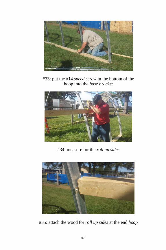
#33: put the #14 speed screw in the bottom of the hoop into the base bracket
#34: measure for the roll up sides
#35: attach the wood for roll up sides at the end hoop
67

#36: attach the wood for roll up side
#37: lay out the covering
#38: unfold the covering, ensuring there are no sharp objects around
68

#39: mark the center point on the cover
#40 & #41: lay out the covering
#42: all hands on deck, prepare to lift the cover onto the structure
69

#43: pulling the cover over from the side, everyone takes a point of the cover to spread it out evenly
#44: lift it up, being careful not to snag on anything
#45: more hands make it easier
70

#46: ensure cover is centered
#47: pull the cover over
#48: almost done, make sure all #49: pull to the end of the structure is even and straight
71

#50: pull tight and start wirelock at the ridge
#51: pull the cover tight as the #52: start putting in wirelock wirelock is going in at the ridge first
#53: put wirelock on both sides at #54: keep the cover tight as you the top are working your way down
with the wirelock
72
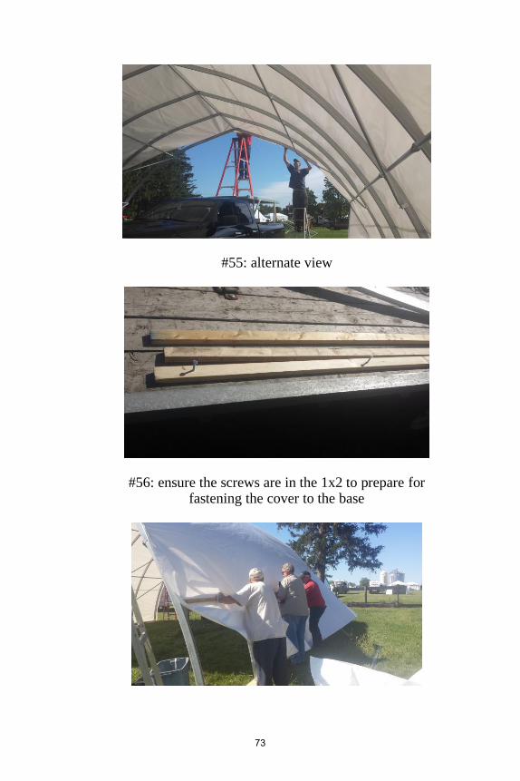
#55: alternate view
#56: ensure the screws are in the 1x2 to prepare for fastening the cover to the base
73

#57: put the wood at the top of the roll up
#58: hold the cover tight as you are installing the wood
#59: sandwich the cover between the 1x2 to secure
#60 & #61: complete this sandwiching technique for both sides of the structure
74

#62 & #63: completed cover fastening
#64: roll the cover around the roll up pipe strap
#65: fasten to the pipe, sandwiching the cover between
75

#66: complete attaching
#67: roll it up and make sure it rolls evenly
#68: finish fastening the cover to #69-pound t-bar anchors in at the pipe diagonal intervals
76

#70 & 71: pound t-bar anchors in at diagonal intervals
#72: fasten the t-bar anchors to the base beam to secure
Remember: There’s no such thing as too many anchors!
77


Instruction Overview The following is an overview of the assembly process and should be used in conjunction with the installation manual AND NOT AS
A STAND ALONE RESOURCE!
Safety is Job #1. Make sure you have the required tools and that they are in good working order! If there is something you do not understand, please call BEFORE you alter anything.
If it does not fit easily, in most cases there may be a simple solution. Altering the structure without calling voids the warranty.
1: The site you pick for your shelter should be fairly level and well drained. Moderate slope on the length is acceptable. Replacement of the topsoil with gravel in a non-growing application will increase drainage and minimize weeds. Building in line with the prevailing wind will create less wind action and stress on the building.
2: The base or anchoring system needs to be installed first. Please remember that our suggestions are based on years of experience but ultimately it is your responsibility to meet local requirements and/or building code requirements. There is no such thing as “too well
anchored” and any extra time spent at this point is well spent.
3. If you are not building on MSS supplied anchor posts the next step is to install the base brackets at spacing equal to the spacing of the stubs on the ridge. The lag bolts are installed in-line with the structure.
4. One of your ridge sections will have stubs at both ends. This is your starter. One person on a ladder or scaffold will hold this at the approximate required height. The person(s) on the ground will slide the top end of the hoop over the ridge stub and the bottom end over the base bracket or anchor post. Fasten the top end of each hoop to the ridge as you go. This prevents something coming loose accidentally and hitting someone.
5. Before continuing on the other ridge pieces the purlins should be attached and then the structure secured in a vertical position with a guide rope. Each additional ridge section with the hoops and purlins is installed until the entire frame is up. If your building is 20’ or less
80

in length you will only have one ridge section. File down any burrs that you may find along the top of the ridge.
6. When the complete structure is standing, ensure the building is straight, (not leaning) secure all of the base fasteners and purlins. Attach all the wind bracing.
7. If your building has been supplied with roll up sidewalls, add the
framing member for the top of the roll up now
8. Install the wirelock track to the topside of the first and last hoop. It is best to start at the bottom and then kink it as you cross the crown. Install the cover fastener along the base as well
9. Frame in the end walls as required. Attach the cover and cut required opening(s). It is preferable to finish the ends before putting the roof on. At certain times of the year, calm days are hard to come by. With a little caution, the roof can be put on first. If the roof covering is
already on, it is important to close the “up wind” end first.
10. If this is the first time you are covering this type of structure, preparation is everything! Whenever possible, roll out the cover along the side of the structure and pull it over the top from the side. Once the cover is centred pull it tight from end to end and secure.
Work from the centre of the end hoops toward the bottom corners.
If your building has double cover, make sure that the bottom layer has been temporarily secured at the side before pulling over the second layer. The bottom layer should be tight while the top layer should just be snug. When the cover(s) are on, fasten all the roll up side wall hardware and then lastly install the inflator fan.
Please ensure you use this in conjunction with the complete
installation manual, photo supplement and online videos to
insure the most success for your structure installation.
As there are so many variations in our structures, we recommend you discussing your installation with a staff member
if there is anything unclear or you are not sure how to alter the instructions for your specific application. Ask BEFORE you
build to avoid cancelling your warranty or running into
irreversible errors.
81


Thank you for your Multi Shelter
Solutions purchase.
We would love to see photos of your finished structure!
Email them to [email protected] and we
will include yours and your company name if we share
them on our social media!