Term Paper Assignment - FM - 2905 - Lupin - EPBA1506 _ Saptaparna Ray

INSTALLATION AND MAINTENANCE MANUAL
IMPORTANT INSTALLATION INSTRUCTIONS WARNING – To reduce risk of severe injury or death:
1. READ AND FOLLOW ALL INSTALLATION INSTRUCTIONS
IMPORTANT SAFETY INSTRUCTIONS WARNING – To reduce risk of injury or death:
READ AND FOLLOW ALL INSTALLATION INSTRUCTIONS
SAVE THESE INSTRUCTIONS
MODEL:
29502950B
Models 2950, 2950B as manufactured by: Automatic Devices Company, Allentown, PA 18103

Table of Contents
Section Description Page
1A Warranty 1 1B Loss or damage 2 1C Description 3 2 Machine Installation and start-up 3 3 Cable Attachment 6 4A Lubrication 7 4B Adjustments 7 4C Cleaning 8 5 Troubleshooting and repair 8 5 Procedure for manual operation (loss of power) 13
Curtain Machine Instruction Manual ADC Track Mounted Curtain Machines
IMPORTANT SAFETY INSTRUCTIONS WARNING – To reduce risk of injury or death:
READ AND FOLLOW ALL INSTALLATION INSTRUCTIONS
SAVE THESE INSTRUCTIONS
Note: Standard machines are designated as Models 2918 and 2917. Machines equipped with friction brakes are designated as Models 2928B and 2917B. The control boxes of the 2928 & 2928B and 2917 & 2917B are NOT interchangeable. The control boxes and baseplates of the machines are stamped with matching serial numbers. BE CERTAIN TO MATCH THE CORRECT CONTROL BOX WITH THE CORRECT MACHINE BY VERIFYING THAT THE SERIAL NUMBERS MATCH.
1. General Information
1. INTRODUCTION 1A. WARRANTY:
(a) Our equipment is guaranteed against defective material and workmanship for a period of one year from date of shipment, provided however that any claim for defective material or workmanship must be made in writing received by us within the appropriate warranty period, and the material or equipment claimed to be defective returned to us whose liability under this guarantee shall be restricted to the replacement or repair of defective materials and workmanship. In no event will we honor any claim for special or consequential damages, nor will we accept back-charges for work performed on our equipment.
(b) If any modifications or alterations are made to our equipment without our prior approval in writing, our warranty automatically becomes invalid.
Machine Manual - Large Machines Page - 1 Automatic Devices Company 2121 South 12th Street Allentown, PA 18103 Phone: 610-797-6000

Machine Manual - Large Machines Page - 2 Automatic Devices Company 2121 South 12th Street Allentown, PA 18103 Phone: 610-797-6000
(c) Our guarantee against defective material and workmanship applies only to the normal and conventional use and application of our equipment, as operated or capable of operation on our plant testing facilities. The guarantee does not apply to unusual, unique, untested or unconventional use and application.
(d) Commodities not manufactured by us are warranted and guaranteed only to the extent and in the manner warranted and guaranteed to us by the manufacturer, and then only to the extent we are able to enforce such warranty or guarantee.
(e) We will not guarantee the satisfactory operation of our curtain machinery when used with curtain track not of our manufacture.
(f) We will not be held responsible for the failure of our equipment to operate properly at the point of installation unless all information, instructions and drawings requisite to the installation of our equipment and to existing job site conditions are furnished to us in writing prior to our formally acknowledging the order. The above warranty provisions will not apply if it is concluded by us that our equipment was not properly installed and that without our prior approval alterations and/or modifications were made to approved shop drawings supplied by us and/or to the job site, subsequent to the submissions of the aforementioned information, instructions and drawings.
(g) The giving of or failure to give any advice or recommendations by us shall not constitute any warranty by or impose any liability upon us.
(h) No liability whatsoever shall attach to us until said products have been paid for.
(i) In the interest of improving the operation, appearance and production of our equipment, we reserve the right to make design changes at any time without giving prior notice to the trade.
1B. LOSS OR DAMAGE:
Even though most shipments are delivered in perfect condition, there is always the possibility of loss or damage. In order to eliminate the possibility of inconvenience and possible additional expense, we urge that you carefully follow these suggestions: When a shipment is delivered to the carrier their agent receipts for it in good condition. It is securely packed; otherwise, they would not accept it and according to the terms on the Bill of Lading, a legally binding contract, the carrier agrees to deliver it to you in the same perfect condition. If these goods are damaged, they should not be accepted until the carrier's agent has noted on the Freight Bill which he will give you, the nature and extent of the damage. He is required to do this. In the same manner, if any goods are lost in transit, have shortage noted on the Freight Bill by agent. The agent's opinion that carrier is not responsible does not bar your claim. He is required to refer your claim to his Claim

Dept.
Concealed Damage: If there should be damage or loss of such a nature that it could not be detected until the goods were unpacked, have the transportation company's agent call AT ONCE and make inspection. Require him to give you a written "Concealed" Bad Order Report, stating the condition of the goods when examined. It is his duty to do this, and you should insist upon it. If he fails to inspect on request, notify by mail within 15 days of delivery and keep a copy of your letter.
We are always willing to handle claims for loss or damage in shipment if the above instructions are complied with. Write us immediately supplying us with an inspection report.
1C. MACHINE DESCRIPTION:
This curtain machine utilizes a single phase AC motor, either split phase or capacitor start, connected to a right angle gear reducer. On “B” models a friction brake is added to the motor or between the motor and the gear reducer. The brake is designed to provide more accurate stopping than a standard machine. A double-grooved cable wheel, which is used to operate the curtain track cable, is mounted on the output shaft of the gear reducer. The wheel is NOT driven by the gear reducer output shaft. The wheel is driven via a cast metal driving dog located above the wheel. The driving dog is keyed to the gear reducer’s shaft and provides power to the drive wheel via a thumb screw threaded through the driving dog and into the drive wheel. IN THE EVENT OF A POWER FAILURE, THE THUMB SCREW CAN BE REMOVED THEREBY FREEING THE WHEEL FROM THE GEAR REDUCER ALLOWING MANUAL OPERATION OF THE TRACK SYSTEM. NOTE THAT POWER MUST BE SHUT OFF AND LOCKED OUT ACCORDING TO OHSA REGULATIONS PRIOR TO ATTEMPTING TO REMOVE THE THUMB SCREW. Track mounted limit switches are furnished with the machine which signal the end of travel for both directions to the machine’s control circuit. A magnetic reversing contactor, control relays, disconnect switch, overload protective breaker and control switches are mounted in or on a sheet steel control enclosure which is remotely located from the track mounted machine. One (1) three-button remote control station is provided with the machine, additional stations are available upon request.
2. MACHINE INSTALLATION AND START-UP
2A. MOUNTING: Machine Manual - Large Machines Page - 3 Automatic Devices Company 2121 South 12th Street Allentown, PA 18103 Phone: 610-797-6000

Machine Manual - Large Machines Page - 4 Automatic Devices Company 2121 South 12th Street Allentown, PA 18103 Phone: 610-797-6000
This curtain machine is designed to be attached to the end of the track using the mounting device provided on the machine’s base. The machine MUST be supported by an overhead structural member at the support points provided on the machine, the curtain track DOES NOT support the weight of the machine.
2B. WIRING:
WARNING – MACHINE MUST BE PERMANTLY WIRED TO ITS POWER SOURCE. POWER SOURCE, REMOTE CONTROLS, AND LIMIT SWITCHES MUST BE WIRED IN ACCORDANCE WITH LOCAL AND NATIONAL ELECTRICAL CODES. ALL CLASS 2 (LOW VOLTAGE) CIRCUITS FROM AND TO MACHINE MUST USE CABLE TYPE CL2, CL2P, CL2R, OR CL2X OR OTHER CABLING WITH THE APPROPRIATE ELECTRICAL, MECHANICAL OR FLAMMABLILITY RATINGS OR PER THE NEC.
Provide correct size service for current rating of machine, as indicated on nameplate. A separate branch circuit for each machine is recommended. Track mounted limit switches must be wired to the machine before the machine is operated. See wiring diagram provided with machine for connection of track mounted limit switches.
Control wiring should be sized according to the type of machine being used. These machines are designed such that the control switches engage electrical relays and thus the maximum in rush voltage is limited 85 VA or less for most machines. These machines are supplied with a low-voltage control circuit (LVCS) which lowers the control voltage of the machine to 24 Vac.
Note: Some machines have Class 2 control circuits and must be wired according to NEC standards for Class 2 circuits. All curtain machines must be grounded. A labeled ground terminal is provided for this purpose within the control enclosure.
Make certain that proper voltage is connected to unit. Do not use an extension cord to provide power to the unit since this will result in a voltage drop to the machine which may cause erratic operation. Check the identification plate of the machine for voltage requirements.

Machine Manual - Large Machines Page - 5 Automatic Devices Company 2121 South 12th Street Allentown, PA 18103 Phone: 610-797-6000
2C. START-UP:
Before applying power, make certain that all parts are free moving and that, if the output wheel rotates, it will not accidentally engage some nearby object or person.
It is suggested that, if possible, initial start-up be made without cables attached to the machine so that problems will not be created if erratic operation is encountered.
If the operating cables from the track are connected to machine, be sure that the master carriers in the track are not attached to the operating cables, or are in a location in the track that will enable them to move without binding or causing damage.
With power applied, and unit either clear of obstructions or connected to cables in a manner which will allow free movement, press either the "OPEN" or "CLOSE" push-button. The motor should start and the wheel of the machine should rotate. Pressing the "STOP" push-button (red) of the should stop all movement. Unit should operate in opposite direction of initial movement when remaining push-button is pressed after machine has stopped. Electrical interlocks prevent reversal while machine it is operating.
If the machine appears to be operating normally, and complete installation is to be made at this time, limit switches can be adjusted at this time. Note that during testing of the limit switches, the machine can be stopped at any time by pressing the STOP button of the remote or local control station.
1. The machine is supplied with 2 limit switches, one (1) for the OPEN
direction and one (1) for the closed direction. Limit switch control direction is determined by the terminals that the switch is wired to in the control box.
2. One of the Master Carriers supplied is equipped with a tripping arm
which is used to activate the roller arm of the limit switches. 3. The limit switches attach to the track via the track clamps provided
with the switch. 4. To adjust the limit switches, locate the switches on the track such that
the master carrier tripping arm will engage the roller of the CLOSED limit switch when the curtain is at its closed location. Locate the OPEN limit switch such that its tripping arm will engage the OPEN limit switch roller when the curtain is in its open location. Note that the

curtain will coast after the machine shuts off. The amount of coast depends on the model track used with the machine and the weight of the curtain. Allowance must be made for this coast when positioning the limit switches.
5. With the track mounted limits in position and tested, the machine can
be run to its full OPEN and CLOSED positions.
If the unit operates satisfactorily in both directions, it is ready to be connected to cords from track.
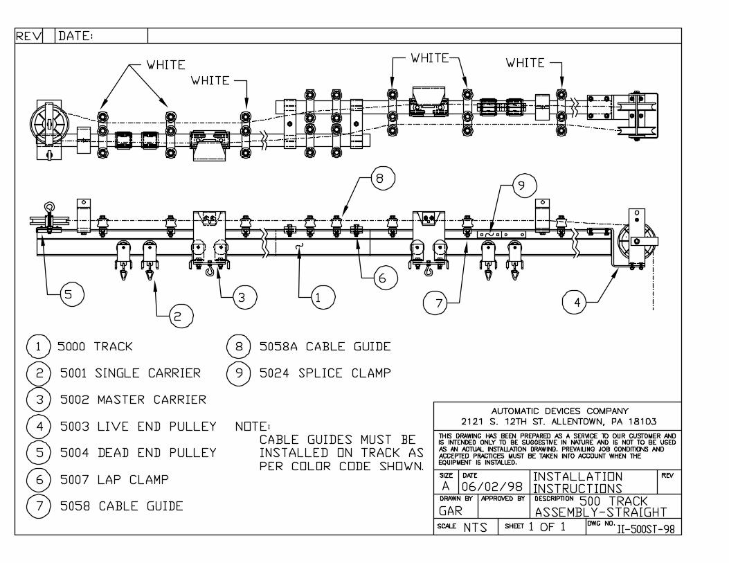
3. CABLE ATTACHMENT
3. GROOVED WHEEL DRIVE:
1. Install and wire the limit switches at the fully closed position of the track system and the fully open position of the track system. Note that the limits should be positioned such that the curtain is not fully compacted when the master carrier reaches the limit switch as the carrier will coast after the switch is activated. Check the position of the switch by manually operating the master carrier until it activates the switch. Note the location of the single carriers, they should not be compressed.
2. Place coil of cable on floor below the machine end of the track system. 3. Thread one end of cable through the machine side master carrier cable
clamp nearest the center overlap of the track system, but do not tighten the cable clamps at this time.
4. Thread cable through the cable guides on the dead-end half of the systems and then around the dead-end pulley
5. With cable now going around the dead end pulley, thread it through the remaining side of the cable guides on the dead-end pulley side of the track system and through the cable clamps of the master carrier located on the dead-end half of the track system, but do not tighten the cable clamps at this time.
6. Continue with the cable to the machine and wrap the cable around the bottom groove of the double-groove drive wheel, then around the tension-idler pulley of the machine, and finally around the top groove of the drive wheel and out toward the track again.
Machine Manual - Large Machines Page - 6 Automatic Devices Company 2121 South 12th Street Allentown, PA 18103 Phone: 610-797-6000
7. Thread the cable through the cable guides of the machine half of the track system. Note that you may need to provide slack to the cable in order to feed it around the drive system of the machine.

8. Thread the cable through the closest (remaining) cable clamp of the machine side master carrier. Allow approximately 10” of excess cable and tighten this cable clamp.
9. Remove as much slack from the track system as possible by pulling on the remaining unsecured end of cable at the machine side master carrier. Make sure to check the cable at the machine and assure that it is fully seated in the drive wheel grooves and that no excess slack is present at the wheel or idler pulley.
10. With all slack removed from the system, tighten the remaining cable clamp of the master carrier located in the machine half of the track system. Allow approximately 10” of excess cable and cut off remaining cable.
11. Operate the machine to the full CLOSED position. Only the master carrier that has been tightened should move. When the machine shuts off, slide the un-tightened master carrier into position at the center overlap and tighten the cable clamps of the carrier.
12. Operate the system several times and make sure it is operating correctly. If it is, the excess cable can be cut from the master carriers. Note, do not cut the cable right at the cable clamp. Leave at least 2 to 3 inches of excess so that cable slack can be removed in the future.
4. MAINTENANCE
4A. LUBRICATION:
Lubricate motor as per instructions on motor nameplate.
Gear reducer is factory filled with 600W super cylinder oil. During average service, the reducer can be considered to be permanently lubricated. If, for some reason, additional lubricant is required, it can be added through an opening at the top of the reducer. Also be sure to remove power prior to performing maintenance on the machine.
4B. ADJUSTMENTS:
All wire-centered cable stretches and slack must be removed from the system periodically. To remove slack, clamp gripping type pliers to one of the cut ends of cable located at the track master carrier. With the cable end secured, loosen the cable clamp of the master carrier and pull out the excess slack from the system. With slack removed, re-tighten the master carrier cable clamp.
Machine Manual - Large Machines Page - 7 Automatic Devices Company 2121 South 12th Street Allentown, PA 18103 Phone: 610-797-6000

Note: The machine operator for this type of system is designed to produce a significant amount of friction on the operating line. Be sure to check the cable slack both before and after the machine. It may be necessary to work the cable slack out by feeding it around the machine’s drive wheel. This machine is equipped with an adjustable tension pulley to add additional tension to the operating line if needed. Note this device applies tension to a taught operating cable only. All slack must be removed from the system at the master carriers before this device is adjusted. The device is adjusted be threading the nut of the device’s assembly to move the pulley wheel away from the main drive wheel, thus applying additional tension to the system.
4C. CLEANING:
With power off, remove debris and foreign objects from vicinity of curtain machine, from between motor and base, motor and frame, and from vicinity of drum. Low-pressure air or a vacuum cleaner can be used for this purpose.
With power off, remove cover from control enclosure. Remove dust and dirt with low- pressure air or vacuum cleaner, being careful not to damage any internal parts. Check and tighten all connections and mounting screws. Replace cover.
5. TROUBLESHOOTING AND REPAIR
It is assumed that the troubleshooting and repair will be performed by individuals with a basic knowledge of electricity, motor controls, with the ability to follow the wiring diagrams enclosed, and who will take the precautions required when working with exposed electrical connections.
In order to perform the procedures listed, basic hand tools plus measuring and indicating equipment are required. A clamp-on type volt-amp-ohmmeter tester with accessories will provide the necessary indication and measurements. Before proceeding with any of the checks listed below, make certain that all connections are tight and any obviously defective or broken parts are replaced. Also make certain that track is operating freely and that cables are in good condition.
Machine Manual - Large Machines Page - 8 Automatic Devices Company 2121 South 12th Street Allentown, PA 18103 Phone: 610-797-6000
When ordering replacement parts for this curtain machine, please give a description of the part and also provide the model number and serial number of the machine.

Machine Manual - Large Machines Page - 9 Automatic Devices Company 2121 South 12th Street Allentown, PA 18103 Phone: 610-797-6000
5A. SYMPTOM: MACHINE WILL NOT START
Possible Cause: Suggested remedy:Incoming Power Off Check with meter, or test light. Disconnect Switch Off Check and reset switch. Circuit Breaker Tripped Check track system for problems or bound
components. If none found, reset breaker. Control Fuse Loose or Blown Tighten cap, or replace fuse. Broken Fuse Holder Replace Jumper “X” (see wiring diagram) removed from terminals 3 & 4 and no remote control station is installed.
Check and install jumper or remote control station.
Faulty remote switch wiring Check remote wiring with electrical meter. Faulty ESR board Check board for electrically open or
damaged components. Check relay contacts (should be NC).
Both limit switches activated Check track mounted limit actuator arm positions. If actuators in correct position, check internal connections of limit switches. (Power Removed)
Defective “STOP” button Check with meter (power removed). Should be NC.
5B. SYMPTOM: MACHINE RUNS IN ONE DIRECTION ONLY
Possible Cause: Suggested remedy:Defective pushbutton (one direction) Check with electrical meter. Defective interlock at contactor Check contactor and electrical interlocks
with electrical meter. Replace contactor if jammed.
Limit switch activated Check track mounted limit switches. Reset actuator arm of limit. If actuator in correct position, check internal wiring of limit switch (power removed).
Defective contactor coil Check continuity of contactor coils. If defective, replace contactor.
Faulty ESR board Check board for electrically open or damaged components. Check relay

Machine Manual - Large Machines Page - 10 Automatic Devices Company 2121 South 12th Street Allentown, PA 18103 Phone: 610-797-6000
contacts (should be NC). Foreign material in contactor Replace contactor (Power Removed) 5C. SYMPTOM: MOTOR RUNS BUT OUTPUT SHAFT DOES NOT TURN
Possible Cause Suggested RemedyDrive wheel set screw loose Check and tighten (power removed) Faulty gear reducer Check and replace (power removed) Faulty motor Check and replace (power removed) 5D. SYMPTOM: NOISY MACHINE
Possible Cause Suggested RemedyDry motor bearing Inspect bearing ends of motor and lubricate
if port available. If no port available, motor will need to be replaced.
Dry gear reducer Inspect oil level of gear reducer. Examine oil for contamination or metal shavings. Replace gear oil if contaminated or fill if level low. Use only recommended gear oil.
Faulty idler pulley assembly Check and replace (power removed) Loose machine mounting bolts Check all mounting hardware. Tighten or
replace as needed. Machine mounted against hollow ceiling, wall, or object.
Change location of machine or fill area machine is attached to or near to deaden area.
5E. SYMPTOM: MACHINE STARTS BUT WILL NOT PULL LOAD
Possible Cause Suggested RemedyWrong incoming voltage or voltage drop on start up.
Check with electrical meter. Wiring may be wrong gauge, run may be too long, or dedicated power source may be needed.
Extension cord providing power to the machine.
Replace with permanent wiring according National Electrical Code standards.
Dry gear reducer Check oil level of reducer. Check oil for contamination. Replace oil or fill reducer to factory level. (power removed)
Defective motor capacitor Check capacitor for physical damage. Check amperage load on start-up and run cycles. Amperage should drop after motor

Machine Manual - Large Machines Page - 11 Automatic Devices Company 2121 South 12th Street Allentown, PA 18103 Phone: 610-797-6000
gets up to speed. Replace capacitor. (power removed). Not capacitor may have residual charge. Discharge prior to removal.
Track system assembled incorrectly Check track system and track installation instructions. Correct as needed.
Defective parts in track Replace any defective or worn track components. (power removed)
5F. SYMPTOM: CIRCUIT BREAKER TRIPS
Possible Cause Suggested RemedyWrong incoming voltage or voltage drop. Check with electrical meter and correct. Defective motor Check motor capacitor for physical damage.
Check starting and running amperage. Amperage should drop after motor gets up to full speed.
Machine undersized for application Check load of system and contact factory for machine rating.
Incorrect or faulty wiring Check wiring at terminal strip. If machine wiring is faulty, return machine to factory for repair.
5G. SYMPTOM: FUSE BLOWS
Possible Cause Suggested RemedyFaulty remote control switch wiring Check wiring with electrical meter. Correct
as needed. Note machine supplies its own control power, no external control power signal should be present.
Loose connection in control box Check wire connections in control box (power removed) and tighten as needed.
Wrong fuse being used Check and replace correct size and type fuse.
Defective mechanical interlock Check and replace contactor if jammed. (power off)
Foreign material in contactor Check and clear debris. Replace contactor if needed.
5H. SYMPTOM: MACHINE WILL NOT STOP AT LIMIT SETTING

Machine Manual - Large Machines Page - 12 Automatic Devices Company 2121 South 12th Street Allentown, PA 18103 Phone: 610-797-6000
Possible Cause Suggested RemedyFaulty remote switch wiring Permanent connection exists between
terminals 1 & 3 or 4, or 2 & 3 or 4. Correct.Faulty limit switch Check track mounted limit switches. Reset
actuator arm of limit. If actuator in correct position, check internal wiring of limit switch (power removed).
Faulty or misaligned master carrier tripping arm
Check and align with limit switch actuator arms.
Limit switch wires not correctly connected Check limit wiring (power removed). Limit wires should be connected to the NC side of the switch.
“OPEN” and “CLOSE” inputs activated simultaneously.
Check automation outputs or remote stations and correct.
5I. SYMPTOM: MOTOR OVERHEATS
Possible Cause Suggested RemedyWrong incoming voltage or voltage drop on start up.
Check with electrical meter. Wiring may be wrong gauge, run may be too long, or dedicated power source may be needed.
Extension cord providing power to the machine.
Replace with permanent wiring according National Electrical Code standards.
Dry gear reducer Check oil level of reducer. Check oil for contamination. Replace oil or fill reducer to factory level. (power removed)
Dry motor bearings Inspect and lubricate if ports available (power removed). Replace if ports not available.
Defective motor Check capacitor for physical damage. Check amperage load on start-up and run cycles. Amperage should drop after motor gets up to speed. Replace capacitor. (power removed). Not capacitor may have residual charge. Discharge prior to removal.
Loose connection in control box Check wiring at terminal strips and in machine control box (power removed). Tighten as needed.
Incorrectly assembled curtain track Check track system and track installation instructions. Correct as needed.
Defective parts in track Replace any defective or worn track components. (power removed)

Machine Manual - Large Machines Page - 13 Automatic Devices Company 2121 South 12th Street Allentown, PA 18103 Phone: 610-797-6000
5J. SYMPTOM: MOTOR STOPS PREMATURELY
Possible Cause Suggested RemedyWrong incoming voltage or voltage drop on start up.
Check with electrical meter. Wiring may be wrong gauge, run may be too long, or dedicated power source may be needed.
Extension cord providing power to the machine.
Replace with permanent wiring according National Electrical Code standards.
Defective STOP button or problem with STOP loop wiring
Check with electrical meter for continuously closed circuit (power removed).
Faulty limit switch. Check track mounted limit switches. Reset actuator arm of limit. If actuator in correct position, check internal wiring of limit switch (power removed).
Incorrectly assembled curtain track Check track system and track installation instructions. Correct as needed.
Defective parts in track Replace any defective or worn track components. (power removed)
5.K PROCEEDURE FOR MANUAL OPERATION IN THE EVENT OF A LOSS OF ELECTRICAL POWER:
1. Shut off electrical power source at nearest disconnect and lock-out the disconnect according to OSHA lock-out regulations.
2. Unscrew thumb screw of driving dog located on top of the machines drive wheel (track level) until it is completely free of the machine’s drive wheel.
3. Operate the track system manually to the desired location. 4. When power is restored, leave disconnect locked out and manually operate the
track system until the thumb screw hole in the drive wheel lines up with the thumb screw hole in the driving dog.
5. Screw the thumb screw into the drive wheel until it is properly seated. 6. Restore power to the system and operate. Limits do not need to be adjusted
since they are a direct strike type.


Installation Photos
Photo 1
Machine Strung
Photo 2
Master Activating Limit

Photo 3
Cable at Machine Side Master Carrier
Photo 4
Top View of Strung Machine

Photo 5
Limit switch location (Shown on 2800 track)
Master Carrier Actuator Arm
Note orientation of limit switch actuators
To machine end of track
To center overlap of track system