IMPLICIT SLICING METHOD FOR ADDITIVE MANUFACTURING...
14
IMPLICIT SLICING METHOD FOR ADDITIVE MANUFACTURING PROCESSES D. W. Adams, C. J. Turner 1 Department of Mechanical Engineering, Clemson University, Clemson, SC 29631 Abstract All additive manufacturing processes involve a distinct preprocessing stage in which a set of instructions, or GCode, that control the process specific manufacturing tool are generated, otherwise known as slicing. In regards to fused deposition modeling, the GCode defines many crucial parameters which are needed to produce a part, including tool path, infill density, layer height, feed rate, tool head and plate temperature. The majority of current commercial slicing programs generate tool paths explicitly, and do not consider particular geometric properties of parts, such as thin walls, small corners and round profiles that can result in critical voids leading to part failure. This work replicates an implicit slicing algorithm in which functionally derived infill patterns are overlaid onto each layer of a part, reducing the possibility of undesired voids and flaws. This work also further investigates the effects that varying implicitly derived infill patterns have on a part’s mechanical properties through tensile testing dog bone specimens with three different infill patterns and comparing ultimate stress and elastic modulus properties. 1. Introduction Although additive manufacturing (AM) has been in practice since the mid 1980’s, it has recently become a more common method of mass part production due to time and cost savings, freedom of design, and the ease of implementation it provides in comparison to other methods of manufacturing [1]. The transition that additive manufacturing has made from being mostly a small market DIY part prototyping fad, to a legitimate industry, capable of providing solutions to previous manufacturing challenges, can be largely attributed to the numerous studies which have been completed to advance our knowledge and perception on this topic. The additive manufacturing industry encompasses several different methods of rapid prototyping including Sterolithography [2], Electron Beam Melting (EBM) [3], Direct Metal Deposition (DMD) [4-5], Selective Laser Sintering [6-8], and Fused Deposition Modeling (FDM). While all of these processes offer unique advantages for particular prototyping applications, they all implement the same preprocessing method known as slicing. A slicer algorithm takes a three- dimensional model and generates a set of basic instructions, known as GCode. This GCode controls every build parameter and every move that the respective manufacturing tool makes throughout the entire build [9]. Slicers work by intersecting the input model with distanced parallel planes to create a set of two dimensional domains; that, when stacked on top of each other, represent the entire model as seen in figure 1. A tool path is then created for each “slice”, and the part is manufactured layer by layer, from the bottom up. 1 Corresponding Author, E: [email protected] 844 Solid Freeform Fabrication 2017: Proceedings of the 28th Annual International Solid Freeform Fabrication Symposium – An Additive Manufacturing Conference Reviewed Paper
Transcript of IMPLICIT SLICING METHOD FOR ADDITIVE MANUFACTURING...

IMPLICIT SLICING METHOD FOR ADDITIVE MANUFACTURING PROCESSES
D. W. Adams, C. J. Turner1
Department of Mechanical Engineering, Clemson University, Clemson, SC 29631
Abstract
All additive manufacturing processes involve a distinct preprocessing stage in which a set of instructions, or GCode, that control the process specific manufacturing tool are generated, otherwise known as slicing. In regards to fused deposition modeling, the GCode defines many crucial parameters which are needed to produce a part, including tool path, infill density, layer height, feed rate, tool head and plate temperature. The majority of current commercial slicing programs generate tool paths explicitly, and do not consider particular geometric properties of parts, such as thin walls, small corners and round profiles that can result in critical voids leading to part failure. This work replicates an implicit slicing algorithm in which functionally derived infill patterns are overlaid onto each layer of a part, reducing the possibility of undesired voids and flaws. This work also further investigates the effects that varying implicitly derived infill patterns have on a part’s mechanical properties through tensile testing dog bone specimens with three different infill patterns and comparing ultimate stress and elastic modulus properties.
1. Introduction
Although additive manufacturing (AM) has been in practice since the mid 1980’s, it has recently become a more common method of mass part production due to time and cost savings, freedom of design, and the ease of implementation it provides in comparison to other methods of manufacturing [1]. The transition that additive manufacturing has made from being mostly a small market DIY part prototyping fad, to a legitimate industry, capable of providing solutions to previous manufacturing challenges, can be largely attributed to the numerous studies which have been completed to advance our knowledge and perception on this topic. The additive manufacturing industry encompasses several different methods of rapid prototyping including Sterolithography [2], Electron Beam Melting (EBM) [3], Direct Metal Deposition (DMD) [4-5], Selective Laser Sintering [6-8], and Fused Deposition Modeling (FDM). While all of these processes offer unique advantages for particular prototyping applications, they all implement the same preprocessing method known as slicing. A slicer algorithm takes a three-dimensional model and generates a set of basic instructions, known as GCode. This GCode controls every build parameter and every move that the respective manufacturing tool makes throughout the entire build [9]. Slicers work by intersecting the input model with distanced parallel planes to create a set of two dimensional domains; that, when stacked on top of each other, represent the entire model as seen in figure 1. A tool path is then created for each “slice”, and the part is manufactured layer by layer, from the bottom up.
1 Corresponding Author, E: [email protected]
844
Solid Freeform Fabrication 2017: Proceedings of the 28th Annual International Solid Freeform Fabrication Symposium – An Additive Manufacturing Conference
Reviewed Paper

Current commercial slicer algorithms generate the tool path for each slice explicitly. In
other words, the tool path is generated by applying a series of predetermined geometric transformations to the interior of each slice without considering overall part geometry. Tool path predetermination can be problematic in various geometric situations, such as thin walls, small corners and round profiles, and parts can be left with critical voids that may lead to failure. Work has been done in developing alternate slicing methods which take part geometry into account to not only solve this issue but also to optimize different features of the slicing and printing process. This work replicates and further investigates an alternative implicit slicing method for fused deposition modeling in an attempt to solve the unfilled region issue that the explicit method presents [10-12]. The implicit algorithm overlays a user defined functionally derived infill pattern onto the intersection perimeter for each slice ensuring that no voids will occur. Additionally, not only does this allow for a much wider array of possible infill patterns, it also allows the manufacturer to apply particular infill patterns that are better suited for an individual part based on its application. This work also experimentally examines the effects that varying implicit infill patterns have on the mechanical properties of a part. While this work does conclude that an implicit slicing method offers a concrete solution to part voids, the current state of the current work does not confirm that implicitly derived infill patterns offer more ideal mechanical properties than explicitly derived infill patterns. Although Stueben et al. state there are material property benefits with implicit infill patterns, further testing to compare the two methods needs to be performed to confirm this claim.
2. Background and Related Work
2.1 Fused Deposition Modeling Fused Deposition Modeling (FDM) is an AM process in which an extruder tool head follows a coded path while extruding a specific amount of thermoplastic filament layer by layer to form a complete part. The thermal properties of the thermoplastic in use allow each layer of the part to bond together which allow the resulting part to be considered one continuous entity. Figure 2 displays the basic process of fused deposition modeling.
Figure 1. Perimeter curves and Delaunay Triangulation of all slices of dog bone specimen
845

A combination of several stepper motors control the x and y locations of the tool head during the build, which are contingent on the infill pattern that is created for each layer. After one layer is completed, a lead screw lowers the build plate a user defined distance so the next layer can be extruded on top of the previous layer. The thermoplastic is heated, and remains in a molten state long enough to allow complete bonding between the layers after extrusion. In particular cases, as the one pictured in figure 1, parts may require support material to ensure that none of the extruded material collapses, causing a build failure. Once the build is complete, the support material is removed by either breaking it off or dissolving it in a material specific solvent. There are many different user defined build process parameters that have been found to significantly affect the overall quality of a part. Some of these parameters include layer height, extrusion resolution, spindle speed, feed rate, part orientation, retraction distance and rate, support material settings, infill pattern, and infill density. All of these parameters collectively affect build properties such as surface roughness, build time, amount of extruded material, and the mechanical properties of the part; therefore, they should all be carefully considered before printing to ensure optimal manufacturability and a quality finished part. Many studies have been completed to exemplify the impact that varying explicitly derived infill patterns have on material properties, such as ultimate strength [14], strain rate, modulus of elasticity and yield strength. One important study that was done by Ziemian et al. experimentally validated the idea that raster orientation significantly affects all of the mechanical properties just listed above [15]. The study implemented four different raster angles, longitudinal (0°), diagonal (45°), transverse (90°), and an alternating +45°/-45°. Results concluded that when the extruded filament was aligned with the direction of the force being applied, the part exhibited much higher values for all mechanical properties including a 35% higher yield strength, 33% higher ultimate strength, and 29% higher elastic modulus than any other test angle. 2.2 Slicing As previously mentioned, every additive manufacturing process undergoes the same preprocessing procedure known as slicing. All slicing programs start with a 3D CAD (Computer Aided Design) model and transform it into a script that the AM machine’s processor can understand and implement to create a working part. Currently the vast majority of commercial and industrial slicer algorithms operate using the same accepted approach, which is considered to be an explicit slicing method. The main defining characteristic of an explicit slicer is that the interior tool path, or infill pattern, for each layer is generated the same way for every single input model, with no regard to the perimeter geometry. The infill path begins at an arbitrary point along the perimeter of the slice, usually close to the ending point of the perimeter, and starts to apply a
Figure 2. FDM Process [13]
846

discrete set of geometric transformations to that path in order to create the desired pattern. This process is done for every layer, excluding the exterior layers of the part, until the part is complete. This slicing method has proven to present an issue with parts containing critical voids, due to an incompatibility of the input geometry with the geometric transformations, such as thin walls and small corners. Figures 3 and 4 displays an example of this problem.
Slicers that explicitly compute tool paths usually offer 5-10 preset infill patterns, with common ones being a honeycomb, linear, rectilinear, diamond, triangle, and concentric. Due to the limited amount of options for infill patterns, users are unable to tailor the infill to a part’s specific needs based on its application. Multiple experimental slicer algorithms have been developed to address both of these issues that explicit slicers present as well as optimizing different aspects of the slicing process. One alternative slicing algorithm, developed by Lu et al., considered object breakability as the backbone of the methodology [16]. The team of researchers drew inspiration from the Voronoi structure to allow printed material to be distributed unevenly. After a FEM stress simulation was implemented on a given model and the data was extracted, the algorithm runs through a series of optimization processes that calculate weight to strength ratios for several nodes that were derived from a density map defined by the stress distribution. This process places more Voronoi cells in areas where the stress is higher so that the extruded material is concentrated in locations where the model is most likely to break. The tool path is then created based on the contours of all of the cells. This method proved to reduce material volume by up to 75% while still maintaining the structural integrity of the model. Micali and Dornfeld developed a three-dimensional slicer for point-based AM systems that enable tool paths to be generated in three dimensions, rather than a planar surface, to preserve as much geometric continuity of the model as possible [17]. It considers the opportunity of improvement for AM machines that have 5+ degrees of freedom (DOF) instead of the standard 2.5 DOF for commercial machines. This method would allow much higher precision and accuracy for machines in the attempt to make a prototyped part as similar to the design as possible. In an effort to significantly reduce prefabrication computation time for the slicing method and mass customization, Ye et al. developed an alternative slicing algorithm that took advantage of the ability to reuse topology information [18]. It was created in order to deliver parts that could more precisely meet individual needs for a similar, yet changing, model without losing efficiency.
Figure 4. Discontinuity between round profile and infill
Figure 4. Model exemplifying lack of infill in thin walls
847

The team proposed to store topological information at three different levels of the prefabrication process, allowing tool paths to be generated for slightly changed models in significantly less time, rather than completely recalculating a tool path every time the model is slightly changed. Another significant issue with conventional explicit slicing is the lack of manufacturability consideration. Tedia and Williams used a voxel-based geometric modeling method to optimize part orientation prior to being prototyped [19]. This was done by defining specific exterior voxels as support voxels based on the angle that their normal makes with the horizontal. An optimization process is then implemented to maintain that the minimum number of support voxels exist. Their findings proved to minimize necessary support material to maintain structural integrity as well as improve time of manufacturing. The purpose of this work is to replicate and optimize an implicit slicing method that was proposed by Stueben et al. This work attempts to address the issue of critical voids in additively manufactured parts, in which explicit methods present, as well as the issue of infill and mass customization. Several infill patterns are generated with this method, and three test cases are prototyped and tensile tested to investigate the effect that varying implicit infill patterns have on mechanical properties.
3. Methodology
3.1 Slicer Development The first process that must occur before a model can be sliced is the transformation of a
3D model into a STL file. A STL file is a set of points in the three-dimensional Cartesian coordinate system that represent nodes of all of the triangles which the model is spliced into when it is meshed, and ultimately the entire model when put together. This process is required so that a computational language, in this case Matlab, can interpret and display the model. After the coordinates are read into a script, the model can then be sliced, and a tool path can be generated.
The first technical step that every planar slicing algorithm implements is finding intersection curves of the model, so that a perimeter curve can be defined for each slice. To do this, parallel planes, which are intersected with the part model and point where the planes intersect the part, are stored and a perimeter curve is created for that one slice. This process is iterated for a calculated number of times, based on the overall part height divided by desired layer thickness. If meshed together, this discrete set of perimeter curves will represent the entire model. For this experiment, a dog bone specimen of 3.0mm thickness was chosen as the base model based on its common use in tensile testing. A layer thickness of 0.2mm was chosen; therefore, 15 layers would be created for this model. Figures 5 and 6 depict this perimeter declaration process with the dog bone specimen.
848

After the outer perimeter curves have been declared, a certain amount of interior offset curves need to be created, based on user definition. Interior curves are necessary to ensure bonding from the infill pattern to the boundary curve, as well as to create a stronger shell for the part. There are many diverse methods for offsetting polygons such as the use of Voronoi diagrams [20, 21]; however, this work implements a signed Euclidean distance function to obtain equidistant interior offset curves [22]. Results of this transform are displayed in figures 7 and 8.
The last step before being able to apply an infill contour to a layer of the model is to define a domain for each slice. The domain represents all of the available space that an infill curve can occupy, ensuring that the infill pattern does not overlap or exit the perimeter contours. At this point, any mathematical function can be applied to the domain of a layer to create infill contours. In essence, a function is being overlaid onto the domain of the slice; therefore, no region of the model will be void due to geometrical complications. After functions are applied to the domain, contour plots with a specific number of contours can be generated, so that the amount of extruded material and overall part mass can be controlled. The points that define each contour are concatenated with each other and then with the set of perimeter curve points in order to make a consolidated list of all the points that the tool head will extrude material over, thus completing the infill pattern for one layer. This process is done for every layer of the model, thus creating a list of every point along the tool path for the entire build. Figure 9 displays various possible functionally derived infill patterns. The final step of the prefabrication phase of a slicing program is GCode generation. All AM machines require a set of instructions that will control every setting and move that the respective tool head will make. This set of instructions is known as GCode. Not only does the GCode script contain the coordinates for the tool path, but it also defines certain print settings that are critical to a successful prototype, including temperature of the tool head and platform, raft settings, tool head speed, retraction distance, and various other preprint procedures that are defined
Figure 6. Plane intersection of model Figure 6. Intersection points resulting from intersection of plane and model
Figure 8. Interior shell contour with an offset distance of .3mm Figure 8. Contour plot of Euclidean distance function
849
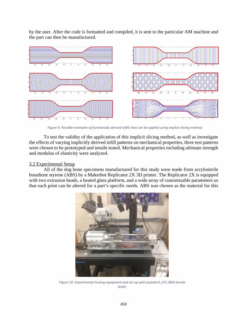
by the user. After the code is formatted and compiled, it is sent to the particular AM machine and the part can then be manufactured.
To test the validity of the application of this implicit slicing method, as well as investigate the effects of varying implicitly derived infill patterns on mechanical properties, three test patterns were chosen to be prototyped and tensile tested. Mechanical properties including ultimate strength and modulus of elasticity were analyzed. 3.2 Experimental Setup All of the dog bone specimens manufactured for this study were made from acrylonitrile butadiene styrene (ABS) by a Makerbot Replicator 2X 3D printer. The Replicator 2X is equipped with two extrusion heads, a heated glass platform, and a wide array of customizable parameters so that each print can be altered for a part’s specific needs. ABS was chosen as the material for this
Figure 9. Possible examples of functionally derived infills that can be applied using implicit slicing method.
Figure 10. Experimental testing equipment and set up with psylotech µTS 10kN tensile tester
850
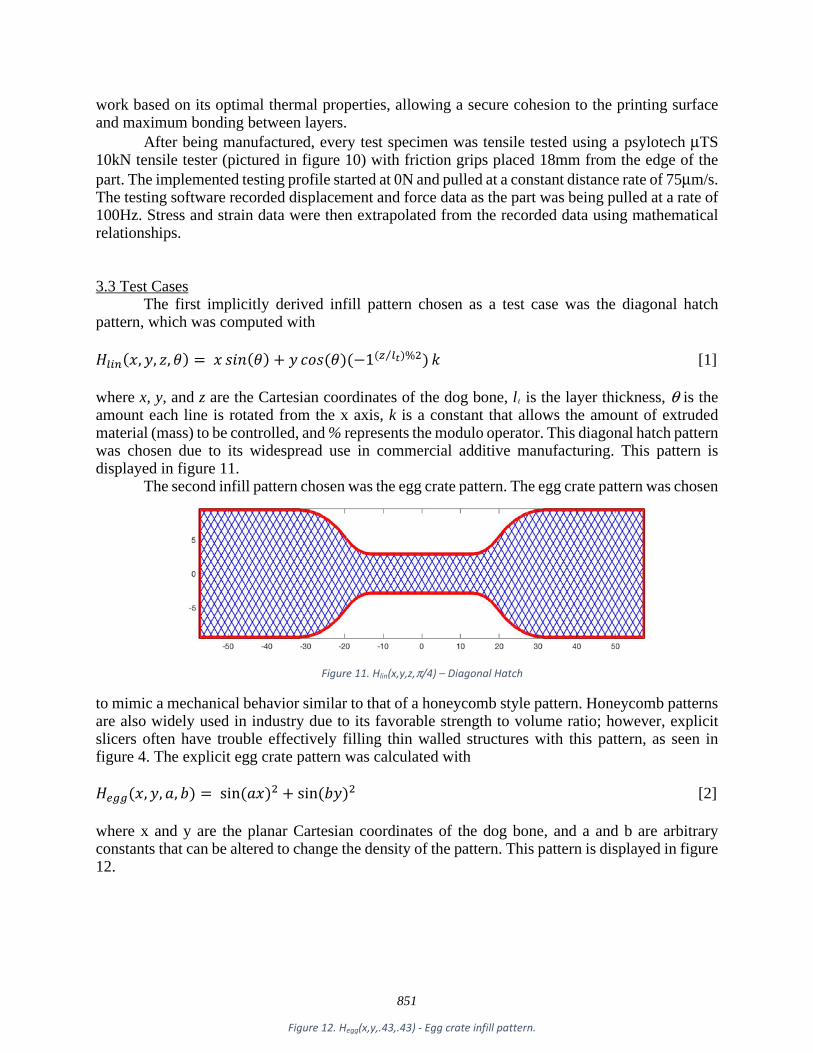
work based on its optimal thermal properties, allowing a secure cohesion to the printing surface and maximum bonding between layers. After being manufactured, every test specimen was tensile tested using a psylotech µTS 10kN tensile tester (pictured in figure 10) with friction grips placed 18mm from the edge of the part. The implemented testing profile started at 0N and pulled at a constant distance rate of 75µm/s. The testing software recorded displacement and force data as the part was being pulled at a rate of 100Hz. Stress and strain data were then extrapolated from the recorded data using mathematical relationships. 3.3 Test Cases The first implicitly derived infill pattern chosen as a test case was the diagonal hatch pattern, which was computed with 𝐻𝐻𝑙𝑙𝑙𝑙𝑙𝑙(𝑥𝑥,𝑦𝑦, 𝑧𝑧,𝜃𝜃) = 𝑥𝑥 𝑠𝑠𝑠𝑠𝑠𝑠(𝜃𝜃) + 𝑦𝑦 𝑐𝑐𝑐𝑐𝑠𝑠(𝜃𝜃)(−1(𝑧𝑧 𝑙𝑙𝑡𝑡⁄ )%2)𝑘𝑘 [1] where x, y, and z are the Cartesian coordinates of the dog bone, lt is the layer thickness, θ is the amount each line is rotated from the x axis, k is a constant that allows the amount of extruded material (mass) to be controlled, and % represents the modulo operator. This diagonal hatch pattern was chosen due to its widespread use in commercial additive manufacturing. This pattern is displayed in figure 11. The second infill pattern chosen was the egg crate pattern. The egg crate pattern was chosen
to mimic a mechanical behavior similar to that of a honeycomb style pattern. Honeycomb patterns are also widely used in industry due to its favorable strength to volume ratio; however, explicit slicers often have trouble effectively filling thin walled structures with this pattern, as seen in figure 4. The explicit egg crate pattern was calculated with 𝐻𝐻𝑒𝑒𝑒𝑒𝑒𝑒(𝑥𝑥,𝑦𝑦,𝑎𝑎, 𝑏𝑏) = sin(𝑎𝑎𝑥𝑥)2 + sin(𝑏𝑏𝑦𝑦)2 [2] where x and y are the planar Cartesian coordinates of the dog bone, and a and b are arbitrary constants that can be altered to change the density of the pattern. This pattern is displayed in figure 12.
Figure 12. Hegg(x,y,.43,.43) - Egg crate infill pattern.
Figure 11. Hlin(x,y,z,π/4) – Diagonal Hatch
851

The final test pattern was generated in part by using contours from a stress distribution, which was obtained by running a FEA simulation on the dog bone specimen using SolidWorks. The force that was applied during the simulation was the same as it would be during actual tensile testing. Based on the fact that material fibers exhibit maximum resistance to failure when force is applied along the same axis as the fiber, (i.e. if the filament was aligned with the stress contours and was more concentrated in regions that experience more stress), the specimen would prove to be stronger and have different failure tendencies. To simulate the same forces that the dog bone would undergo during testing, a force of 125N was applied to the top and bottom faces of the left side of the dog bone with a grip length of 18mm while the right side of the model was fixed. A stress distribution was then obtained from the results of the simulation. Having an infill pattern comprised of only the stress contours would be insufficient due to resulting large gaps in the model; therefore, modifications must be made. The stress derived infill pattern was computed with 𝐻𝐻𝑙𝑙𝑙𝑙 = 𝜎𝜎𝑣𝑣𝑣𝑣(𝑥𝑥,𝑦𝑦, 𝑧𝑧)𝐻𝐻𝑙𝑙𝑙𝑙𝑙𝑙(𝑥𝑥,𝑦𝑦, 𝑧𝑧,𝜋𝜋 4⁄ ) 𝑘𝑘 [3] where σvm(x,y,z) is the three dimensional mesh of the stress values post simulation. The combination of the stress distribution and the linear hatch contour plots concentrate more contours in regions that experience the highest stress values, as mentioned previously. Figure 13 displays the contour plots that comprise the final stress derived infill pattern, which can be seen in figure 14.
4. Results
4.1 Test Case 1 – Diagonal Hatch Upon testing, all specimens with a diagonal hitch infill pattern failed in the neck region; however, the exact failure location was not consistent. Failure location was evenly spread out along the neck and no failure trend was apparent. Further visual inspection indicated that the failure was a very brittle, uneven break into two distinct parts of varying proportion. Additionally, specimens with the diagonal hatch pattern displayed deformation behavior similar to that of a solid sample, as most deformation occurred on either side of the failure.
852

The total amount of extruded material for each print in this test case was 1348.78mm. Samples for this test case had an average mass of 3.197 grams and an average print time of 45 minutes. Regarding mechanical properties for the diagonal hatch infill pattern, the average ultimate stress was 14.6 MPa, and the average elastic modules was 1.08 GPa. 4.2 Test Case 2 – Egg Crate Specimens with the egg crate infill pattern all failed in the transition region that lies between the grip and neck regions. Visually, the failures can be described as a very sudden, brittle fracture. After inspection, the bulk of deformation occurred at the fracture point, while the rest of the specimen underwent very little deformation. The total amount of extruded material for the egg crate infill pattern was 1384.49mm. Samples for this test case had an average print time of 44 minutes and an average mass of 3.013 grams. The mean ultimate stress was the minimum out of all three test cases at 14.3 MPa. The average elastic modulus was less than that of the stress derived test case but still more than the diagonal hatch infill pattern with a value of 1.14 GPa. 4.3 Test Case 3 – Stress Derived Pattern Failures for specimens with the stress derived infill pattern were much more inconsistent than those in test cases 1 and 2. All of the failures began with a small crack on the perimeter of the sample, which eventually propagated. There was an even distribution of samples which failed due to fatal deformation at the point where the grips clamp the sample and failures that were located at the transition region of the dog bone.
e a c d b
Figure 13. (a) Stress derived contour plot (b) Diagonal hatch for odd numbered layers (c) Infill pattern for odd numbered layers (d) Diagonal hatch for even numbered layers (e) Infill pattern for even numbered layers
Figure 14. 𝐻𝐻𝑙𝑙𝑙𝑙 = 𝜎𝜎𝑣𝑣𝑣𝑣(𝑥𝑥,𝑦𝑦, 𝑧𝑧)𝐻𝐻𝑙𝑙𝑙𝑙𝑙𝑙(𝑥𝑥,𝑦𝑦, 𝑧𝑧,𝜋𝜋 4⁄ ) 𝑘𝑘 - Stress derived infill pattern.
853

The amount of extruded material for the stress derived infill pattern was 1352.13mm. Samples for this test case had an average print time of 43 minutes and an average mass of 3.135 grams. This mass is less than the average mass noted in test case 1, which can be attributed to the complexity of the pattern. The average ultimate stress for this test case was 15.9 MPa, and the average modulus of elasticity was 1.31 GPa. 4.3 Analysis A table comparing the nominal values of all measured variables is displayed in Table 1.
The independent variables part geometry, mass, and extruded filament were all held at a
constant within a small margin of error to exemplify the effects that varying infill patterns have on mechanical properties. Quantitatively, the stress derived infill pattern exhibited the largest value for ultimate stress the other test cases by roughly ~10%. In regards to the elastic moduli of all three infill patterns: none of the test cases exhibited strain values greater than 2%. Theoretically, this indicates that, on average, none of the specimens entered an inelastic state. In this case, the average modulus of each test case was calculated by creating a linear line of best fit for each data set. The stress derived infill patterns demonstrated an average modulus ~20% greater than that of the diagonal hatch pattern and ~6% greater than that of the egg crate pattern. This supports the claims hypothesized based on the alignment of the extruded filament with stress contours. Figure 15 displays average stress vs. strain curves with lines of best fit for each test case.
Table 1. Table comparing the experimental values for all 3 test cases
854
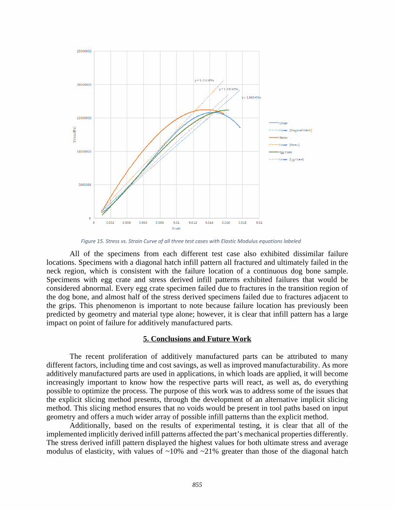
All of the specimens from each different test case also exhibited dissimilar failure locations. Specimens with a diagonal hatch infill pattern all fractured and ultimately failed in the neck region, which is consistent with the failure location of a continuous dog bone sample. Specimens with egg crate and stress derived infill patterns exhibited failures that would be considered abnormal. Every egg crate specimen failed due to fractures in the transition region of the dog bone, and almost half of the stress derived specimens failed due to fractures adjacent to the grips. This phenomenon is important to note because failure location has previously been predicted by geometry and material type alone; however, it is clear that infill pattern has a large impact on point of failure for additively manufactured parts.
5. Conclusions and Future Work The recent proliferation of additively manufactured parts can be attributed to many different factors, including time and cost savings, as well as improved manufacturability. As more additively manufactured parts are used in applications, in which loads are applied, it will become increasingly important to know how the respective parts will react, as well as, do everything possible to optimize the process. The purpose of this work was to address some of the issues that the explicit slicing method presents, through the development of an alternative implicit slicing method. This slicing method ensures that no voids would be present in tool paths based on input geometry and offers a much wider array of possible infill patterns than the explicit method.
Additionally, based on the results of experimental testing, it is clear that all of the implemented implicitly derived infill patterns affected the part’s mechanical properties differently. The stress derived infill pattern displayed the highest values for both ultimate stress and average modulus of elasticity, with values of ~10% and ~21% greater than those of the diagonal hatch
Figure 15. Stress vs. Strain Curve of all three test cases with Elastic Modulus equations labeled
855
specimens respectively. Gathering experimental data of mechanical properties for a statistically significant sample of infill patterns would allow an appropriate implicitly derived infill pattern to be automatically generated, based on input geometry, desired mechanical properties under a particular load, and failure location.
While there is currently a significant amount of work being done in attempts to optimize infill patterns within the AM industry, there is still much that can be done. The most advantageous next step, beyond this work, would be to prototype and mechanically test additional infill patterns to see how they behave when subjected to different loading, including bending, torsion, and compression. If a statistically significant amount of data was collected for many different infill patterns under different loads, neural networks could be formed and the optimal infill pattern could be determined. Ideally, instead of the user arbitrarily defining an infill pattern, it would be automatically selected based on desired mechanical properties and input geometry. Additionally, applying this slicer algorithm and testing procedure to additively manufactured metal parts would be beneficial. Another study which could further this work would be the development of a mathematical function that could be implemented with the implicit slicer which would control density of the part. Being able to control the density throughout a part would ultimately allow you to control the failure location, which could be useful in certain applications, such as shear pins.
ACKNOWLEDGEMENTS
The authors would like to acknowledge the support of Clemson University and the Naval Research Laboratory in this work. All statements within are those of the authors and may or may not represent the views of these institutions.
REFERENCES [1] Thrimurthulu, K., Pandey, P.M., and Reddy, N.V., “Optimum part deposition in fused
deposition modeling.” Journal of Machine Tools & Manufacture 2004: 585-594. [2] Jacobs Paul Francis. “Rapid prototyping & manufacturing: fundamentals of
stereolithography.” Society of Manufacturing Engineers; 1992. [3] Murr Lawrence E, Gaytan Sara M, Ramirez Diana A, Martinez Edwin, Hernandez Jennifer,
Amato Krista N, Shindo Patrick W, Medina Francisco R, Wicker Ryan B. “Metal fabrication by additive manufacturing using laser and electron beam melting technologies.” Journal of Material Science Technology 2012;28(1):1–14.
[4] Lewis Gary K, Schlienger Eric. “Practical considerations and capabilities for laser assisted direct metal deposition.” Material Design 2000;21(4):417–23.
[5] Mazumder J, Dutta D, Kikuchi N, Ghosh A. “Closed loop direct metal deposition: Art to part.” Opt Lasers Eng 2000;34(4–6):397–414.
[6] Gibson Ian, Shi Dongping. “Material properties and fabrication parameters in selective laser sintering process.” Rapid Prototyping Journal 1997;3(4):129–36.
[7] Kruth JP, Wang X, Laoui T, Froyen L. “Lasers and materials in selective laser sintering.” Assembly Automation 2003;23(4):357–71.
[8] Kruth JP, Mercelis P, Van Vaerenbergh J, Froyen L, Rombouts M. “Binding mechanisms in selective laser sintering and selective laser melting.” Rapid Prototyping Journal 2005;11(1):26–36.
[9] ReplicatorG, “What is GCODE.” From http://replicat.org/primer. [10] Stueben, J., Iliopoulos, A., Michopoulos, J.G., “Implicit slicing for functionally tailored
additive manufacturing.” Computer-Aided Design 2016.
856

[11] Huang Pu, Wang Charlie C L, Chen Yong. “Intersection-free and topologically faithful slicing of implicit solid.” J Computer Information Science Engineering 2013;13(2):021009.
[12] Huang Pu, Wang CharlieCL, Chen Yong. “Algorithms for layered manufacturing in image space.” In: Advances in computers and information in engineering research, volume 1. 2014. p. 377–409.
[13] Baich, L., and Manogharan, G., “Study of infill print parameters on mechanical strength and production cost-time of 3D printed ABS parts.”
[14] Bagsik, A., “Mechanical properties of fused deposition modeling parts manufactured with ultem*9083.” ANTEC 2011.
[15] Ziemian, C., Sharma, M., and Ziemian, S., “Ansiotropic mechanical properties of ABS parts fabricated by fused deposition modeling.”
[16] Lu, L., Sharf, A., Zhao, H., et al., “Build-to-Last: Strength to Weigtht 3D Printed Objects.” ACM Transactions on Graphics (TOG) – Proceedings of AM SIGGRAPH 2014:33(4)
[17] Micali, M. K., Dornfeld, D., “Fully Three-Dimensional Toolpath Generation For Point-Based Additive Manufacturing Systems.” Solid Freeform Fabrication Symposium 2016:27
[18] Ye, H., Zhou, C., Xu, W., “Mass Customization: Reuse of Topology Information to Accelerate Slicing Process for Manufacturing.” Solid Freeform Fabrication Symposium 2016:27
[19] Tedia, S., Williams, C. B., “Manufacturability Analysis Tool for Additive Manufacturing Using Voxel-Based Geometric Modeling.” Solid Freeform Fabrication Symposium 2016:27
[20] Held Martin. “Voronoi diagrams and offset curves of curvilinear polygons.” Comput-Aided Design 1998;30(4):287–300.
[21] Kim Deok-Soo. “Polygon offsetting using a Voronoi diagram and two stacks.” Comput-Aided Design 1998;30(14):1069–76.
[22] Lin Zhiwei, Fu Jianzhong, He Yong, Gan Wenfeng. “A robust 2d point-sequence curve offset algorithm with multiple islands for contour-parallel tool path.” Computer Aided Design 2013;45(3):657–70.
857


![Implicit Slicing for Fu nctionally Tailored Additive ... · A review of early work in this vein may be found in [16–19]. Various improvements to these early algorithms, generally](https://static.fdocuments.us/doc/165x107/5f092f327e708231d425a0c5/implicit-slicing-for-fu-nctionally-tailored-additive-a-review-of-early-work.jpg)